26114745-GSM-SP9_Users_M... .pdf
26114745-GSM-SP9_Users_M... .pdf
26114745-GSM-SP9_Users_M... .pdf

Create successful ePaper yourself
Turn your PDF publications into a flip-book with our unique Google optimized e-Paper software.
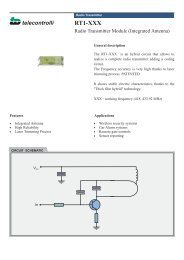
7.1.1 Initialization<br />
Enter 4 to 8 digit PIN code of<br />
the SIM card which is inserted<br />
in the <strong>SP9</strong> device. (Leave the<br />
PIN field empty if usage of the<br />
PIN code on the SIM card is<br />
disabled).<br />
7.1.2 Response to<br />
STATE<br />
The Station Name identifies<br />
the <strong>SP9</strong> device. This text is<br />
placed at the beginning of every sent SMS message. It’s also possible add items<br />
Show Battery status and Show <strong>GSM</strong> strength to status SMS by checking these items.<br />
power supply. The value “L” means <strong>SP9</strong> is battery powered. Events and state SMS<br />
are configured like for any other digital input.<br />
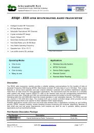
7.3 SPInit - Tab “Digital Outputs”<br />
On this tab, you can set<br />
configuration of all digital<br />
outputs of <strong>SP9</strong> device.<br />
(These outputs have only<br />
two states: YES – NO).<br />
These texts will appear in<br />
the status SMS.<br />
7.1.3 Special actions<br />
Use button Actions on power supply recovery to specify the text of SMS messages<br />
or voice calls which the <strong>SP9</strong> device sends on startup (see chapter Inputs Events).<br />
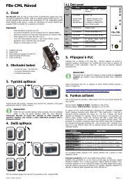
7.2 SPInit - Tab “Digital Inputs”<br />
On this tab, you can set<br />
configuration of all digital<br />
inputs of <strong>SP9</strong> device.<br />
(These inputs have only two<br />
states: YES – NO).<br />
These texts will appear in<br />
the status SMS.<br />
Note: Inputs DIn10 and<br />
DIn11 are not available for<br />
the <strong>SP9</strong>-A and <strong>SP9</strong>-T.<br />
7.2.1 Text in Messages<br />
Input Name, State L, State H<br />
These fields contain names of inputs and their possible states, which are listed in<br />
the status SMS message.<br />
Example:<br />
When we assign Input as “Input1”, “State L” as Off and “State H” as On, the part of<br />
SMS status message concerning Input1 will look like this “Input1=On”.<br />
Mention in State SMS<br />
If this box is checked, the status of this input will appear in the status SMS<br />
message.<br />
Remember after turn off<br />
If this box is checked, the digital input state before switching off of the <strong>SP9</strong> will be<br />
remembered. This is important when <strong>SP9</strong> has to send an SMS message (or make<br />
voice calls) and the input state changes during a power on of <strong>SP9</strong>. Details are<br />
provided in analog inputs.<br />
7.2.2 Change Notification<br />
Transition L => H, transition H => L<br />
When the input level is changed than after delay (which is necessary for the<br />
recognition of the input state) the requested action (SMS or voice call) is performed.<br />
Delay (h: m: s)<br />
Specifies how long new input state must be stable before action is executed.<br />
(Note: the delay timers are nonlinear and it may happen that the program adjusts<br />
your choice at the earliest possible time, e.g. 25:0:5 is adjusted to 25:0:0).<br />
Actions<br />
Here is possible to select what SMS messages or calls the device has to send when<br />
the status changes (see "Events at the inputs").<br />
Actions (SMS or voice calls) to be done on the transition of input signal. (See the<br />
chapter “Inputs Events“).<br />
Negate<br />
If this box is checked, the meaning of states L (inactive) and H (active) is opposite.<br />
7.2.3 Internal input "PWW" - power<br />
<strong>SP9</strong> has an internal digital input PWW (internally X12 input e.g. for MACRO), which<br />
monitors the supply voltage. The value “H” means the <strong>SP9</strong> is powered from external<br />
7.3.1 Text in Messages<br />
Output Name, State L, State H<br />
These fields contain names of outputs and their possible states, which are listed in<br />
the status SMS message.<br />
Example:<br />
If you name the Output “Output1”, Status L “Off” and Status H “On”, than you will<br />
see the following text in the status SMS: "Output1 = Off".<br />
Mention in State SMS<br />
If this box is checked, the status of this output will appear in the status SMS.<br />
Startup<br />
After power on, the <strong>SP9</strong> can set an output to "State L", "State H" or retain the<br />
status output that was before power off (option "Remember").<br />
7.3.2 Impulses<br />
Command<br />
The text used in the command SMS for generating of a pulse on the output (e.g.<br />
"pulse").<br />
Duration (h: m: s)<br />
Specifies duration of the output pulse.<br />
(Note: the duration timers are nonlinear and it may happen that the program<br />
adjusts your choice at the earliest possible time, e.g. 25:0:5 is adjusted to 25:0:0).<br />
Negate<br />
If this box is checked, the meaning of states L (inactive) and H (active) is opposite.<br />
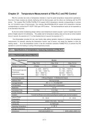
7.4 SPInit - Tab “Analog Inputs”<br />
On this tab is selected configuration for analog input A1 variant <strong>SP9</strong>-A and <strong>SP9</strong>-T.<br />
7.4.1 Text in Messages<br />
Analog Input Name<br />
These fields contain names of<br />
inputs and their possible states,<br />
which are listed in the status<br />
SMS message.<br />
Example:<br />
When we assign Input A1 as<br />
“Current” and check the “Zone”<br />
and “Value”, the part of SMS<br />
status message concerning input<br />
A1 will look like this<br />
“Current=High 20mA” for<br />
example.<br />
Mention in state message<br />
If this box for Zone and/or Value is checked, the Zone and/or Value of this analog<br />
input will appear in the status SMS message.<br />
Filter constant<br />
For each analog input is possible to set by the filter value in range 0.2 sec to 30 sec<br />
or without filter.<br />
Remember after turn off<br />
<strong>GSM</strong>-<strong>SP9</strong>_<strong>Users</strong>_Manual_EN_v1-14.docx / 2013-04-26 page #3 of 6