XRAY T3 Set-up Book - Petit RC
XRAY T3 Set-up Book - Petit RC
XRAY T3 Set-up Book - Petit RC

Create successful ePaper yourself
Turn your PDF publications into a flip-book with our unique Google optimized e-Paper software.
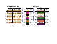
ROLL CENTER – ADJUSTING USING LOWER ARM POSITION<br />
Adjusting the position of the lower arms will produce the largest changes in roll center. This is done by using the different offset lower suspension<br />
holders: 0mm (standard), +0.75mm (raised), and -0.75mm (lowered).<br />
A) Raise the roll center – Raising the lower arm inner hinge pin will raise the roll center. Replace both of the arms standard 0mm<br />
suspension holders with +0.75mm suspension holders.<br />
B) Lower the roll center – Lowering the lower arm inner hinge pin will lower the roll center. Replace both of the arms standard 0mm<br />
suspension holders with -0.75mm suspension holders.<br />
FRONT Lower Arm Position<br />
REAR Lower Arm Position<br />
Higher Roll Center +0.75mm<br />
Standard Roll Center<br />
Lower Roll Center -0.75mm<br />
LOWER<br />
Roll Center Position:<br />
-0.75mm<br />
STANDARD<br />
Roll Center Position:<br />
0mm<br />
HIGHER<br />
Roll Center Position:<br />
+0.75mm<br />
ROLL CENTER - ADJUSTING USING UPPER CAMBER LINK POSITION<br />
To fine tune the front or rear roll center, adjustments can be made to the angle and length of the camber links. Note that changing the <strong>up</strong>per link<br />
angle or length will affect the amount of camber rise/gain. The more angled the camber link, or shorter the length, the more camber gain the wheels<br />
will have as the chassis rolls.<br />
The length of the camber links primarily affects camber gain primarily, but it also affects the rate at which the roll center shifts as the chassis rolls.<br />
Changing the camber link angle affects grip throughout the entire corner, while changing the length has more of an effect in the middle of the<br />
corners.<br />
A) Raise the roll center (shorten or increase the angle of the links)<br />
• Increase the height of the camber link OUTER ball joint by placing shims between the ball joint and the hub.<br />
• Decrease the height of the camber link INNER ball joint by using one of the LOWER Quick Roll Center positions on the shock tower.<br />
• Shorten the camber link by using one of the OUTER <strong>XRAY</strong> Quick Roll Center positions on the shock tower. Remember to mount the<br />
outer ball joint to the INNER mounting position on the hubs, and adjust the length to achieve the proper camber angle.<br />
NOTE: Camber gain will increase as the chassis rolls.<br />
B) Lower the roll center (lengthen or decrease the angle of the links)<br />
• Decrease the height of the camber link OUTER ball joint by removing shims in between the joint and the hub.<br />
• Increase the height of the camber link INNER ball joint by using one of the <strong>up</strong>per <strong>XRAY</strong> Quick Roll Center positions on the shock tower<br />
• Lengthen the camber link by using one of the INNER <strong>XRAY</strong> Quick Roll Center positions on the shock tower. Remember to mount the<br />
outer ball joint to the OUTER mounting position on the hubs, and adjust the length to achieve the proper camber angle.<br />
NOTE: Camber gain will decrease as the chassis rolls. We recommend that the camber link always be angled so the outer ball joint is higher<br />
than the inner ball joint.<br />
front Upper Camber Link Position<br />
REAR Upper Camber Link Position<br />
27