Installation Instructions for Battery Powered Sensor Activated ...
Installation Instructions for Battery Powered Sensor Activated ...
Installation Instructions for Battery Powered Sensor Activated ...

Create successful ePaper yourself
Turn your PDF publications into a flip-book with our unique Google optimized e-Paper software.
Code No. 0816321<br />
Rev. 3 (08/10)<br />
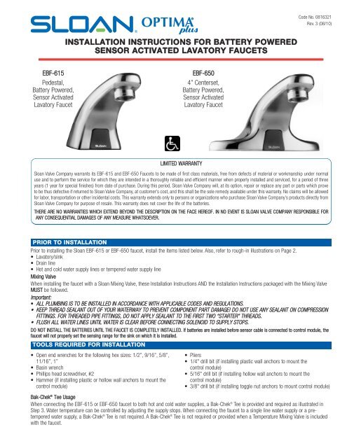
INSTALLATION INSTRUCTIONS FOR BATTERY POWERED<br />
SENSOR ACTIVATED LAVATORY FAUCETS<br />
EBF-615<br />
Pedestal,<br />
<strong>Battery</strong> <strong>Powered</strong>,<br />
<strong>Sensor</strong> <strong>Activated</strong><br />
Lavatory Faucet<br />
EBF-650<br />
4” Centerset,<br />
<strong>Battery</strong> <strong>Powered</strong>,<br />
<strong>Sensor</strong> <strong>Activated</strong><br />
Lavatory Faucet<br />
LIMITED WARRANTY<br />
Sloan Valve Company warrants its EBF-615 and EBF-650 Faucets to be made of first class materials, free from defects of material or workmanship under normal<br />
use and to per<strong>for</strong>m the service <strong>for</strong> which they are intended in a thoroughly reliable and efficient manner when properly installed and serviced, <strong>for</strong> a period of three<br />
years (1 year <strong>for</strong> special finishes) from date of purchase. During this period, Sloan Valve Company will, at its option, repair or replace any part or parts which prove<br />
to be thus defective if returned to Sloan Valve Company, at customer’s cost, and this shall be the sole remedy available under this warranty. No claims will be allowed<br />
<strong>for</strong> labor, transportation or other incidental costs. This warranty extends only to persons or organizations who purchase Sloan Valve Company’s products directly from<br />
Sloan Valve Company <strong>for</strong> purpose of resale. This warranty does not cover the life of the batteries.<br />
THERE ARE NO WARRANTIES WHICH EXTEND BEYOND THE DESCRIPTION ON THE FACE HEREOF. IN NO EVENT IS SLOAN VALVE COMPANY RESPONSIBLE FOR<br />
ANY CONSEQUENTIAL DAMAGES OF ANY MEASURE WHATSOEVER.<br />
PRIOR TO INSTALLATION<br />
Prior to installing the Sloan EBF-615 or EBF-650 faucet, install the items listed below. Also, refer to rough-in illustrations on Page 2.<br />
• Lavatory/sink<br />
• Drain line<br />
• Hot and cold water supply lines or tempered water supply line<br />
Mixing Valve<br />
When installing the faucet with a Sloan Mixing Valve, these <strong>Installation</strong> <strong>Instructions</strong> AND the <strong>Installation</strong> <strong>Instructions</strong> packaged with the Mixing Valve<br />
MUST be followed.<br />
Important:<br />
• ALL PLUMBING IS TO BE INSTALLED IN ACCORDANCE WITH APPLICABLE CODES AND REGULATIONS.<br />
• KEEP THREAD SEALANT OUT OF YOUR WATERWAY TO PREVENT COMPONENT PART DAMAGE! DO NOT USE ANY SEALANT ON COMPRESSION<br />
FITTINGS. FOR THREADED PIPE FITTINGS, DO NOT APPLY SEALANT TO THE FIRST TWO “STARTER” THREADS.<br />
• FLUSH ALL WATER LINES UNTIL WATER IS CLEAR BEFORE CONNECTING SOLENOID TO SUPPLY STOPS.<br />
DO NOT INSTALL THE BATTERIES UNTIL THE FAUCET IS COMPLETELY INSTALLED. If batteries are installed be<strong>for</strong>e sensor cable is connected to control module, the<br />
faucet will not properly set the sensing range <strong>for</strong> the sink on which it is installed.<br />
TOOLS REQUIRED FOR INSTALLATION<br />
• Open end wrenches <strong>for</strong> the following hex sizes: 1/2”, 9/16”, 5/8”,<br />
11/16”, 1”<br />
• Basin wrench<br />
• Phillips head screwdriver, #2<br />
• Hammer (if installing plastic or hollow wall anchors to mount the<br />
control module)<br />
• Pliers<br />
• 1/4" drill bit (if installing plastic wall anchors to mount the<br />
control module)<br />
• 5/16" drill bit (if installing hollow wall anchors to mount the<br />
control module)<br />
• 3/8" drill bit (if installing toggle nut anchors to mount control module)<br />
Bak-Chek ® Tee Usage<br />
When connecting the EBF-615 or EBF-650 faucet to both hot and cold water supplies, a Bak-Chek ® Tee is provided and required as illustrated in<br />
Step 3. Water temperature can be controlled by adjusting the supply stops. When connecting the faucet to a single line water supply or a pretempered<br />
water supply, a Bak-Chek ® Tee is not required. A Bak-Chek ® Tee is not required or provided when a Temperature Mixing Valve is included<br />
with the faucet.
FAUCET ROUGH-IN<br />
EBF-615 Faucet with Bak-Chek ® Tee <strong>for</strong> Hot and<br />
Cold Water Supply (shown with 4” trim plate)<br />
EBF-615 Faucet with ADM Variation Mixing Valve <strong>for</strong><br />
Hot and Cold Water Supply (shown with 8” trim Plate)<br />
EBF-615 Faucet with BDM and BDT Variation<br />
Mixing Valves <strong>for</strong> Hot and Cold Water Supply<br />
(shown with 4” trim Plate)<br />
ADAPTER<br />
(OPTIONAL)<br />
ADAPTER ADAPTER<br />
(OPTIONAL) (OPTIONAL) (OPTIONAL)<br />
ADAPTER ADAPTER<br />
(OPTIONAL) (OPTIONAL)<br />
ADAPTER<br />
(OPTIONAL)<br />
ADAPTE<br />
(OPTIONA<br />
ADAPTER<br />
(OPTIONAL)<br />
EBF-650 Faucet with Bak-Chek ® Tee<br />
<strong>for</strong> Hot and Cold Water Supply<br />
EBF-650 Faucet with BDM and BDT Variation Mixing<br />
Valves <strong>for</strong> Hot and Cold Water Supply<br />
ADAPTER<br />
(OPTIONAL)<br />
FAUCET SIDE VIEW<br />
ADAPTER<br />
(OPTIONAL)<br />
ADAPTER<br />
(OPTIONAL)<br />
ADAPTER<br />
(OPTIONAL)<br />
ADAPTER<br />
(OPTIONAL)<br />
EBF-615<br />
EBF-650<br />
1A - Install Faucet Spout and Optional Trim Plate — EBF-615<br />
Sloan Valve Company recommends installation of our trim plate with antirotation<br />
feature to prevent rotation of this single-hole pedestal-style faucet.<br />
A<br />
Install Faucet Spout as shown. Use plumber’s putty to secure optional<br />
Trim Plate, if used.<br />
Important: After installing Mounting Nut, apply thread sealant or Teflon<br />
tape to threads of Water Supply Tube.<br />
1/4” NPT<br />
WATER SUPPLY<br />
TUBE<br />
APPLY THREAD SEALANT<br />
AFTER INSTALLING<br />
MOUNTING NUT<br />
APPLY PLUMBER’S<br />
PUTTY AROUND EDGE<br />
SPACER<br />
FAUCET<br />
BASE GASKET<br />
TRIM PLATE<br />
(OPTIONAL)<br />
2<br />
MOUNTING SPACER<br />
FLAT WASHER<br />
LOCKWASHER<br />
MOUNTING NUT<br />
FAUCET SENSOR CABLE<br />
1/4” NPT PIPE TO 3/8” TUBE<br />
COMPRESSION FITTING
1B - Install Faucet Spout — EBF-650<br />
Refer to the <strong>Installation</strong> <strong>Instructions</strong> included with the ETF-578-A Trim Plate<br />
<strong>for</strong> additional in<strong>for</strong>mation about using an 8" Trim Plate with an EBF-650<br />
faucet.<br />
A<br />
Install Faucet Spout as shown.<br />
Important: Apply thread sealant or Teflon tape to threads of Water<br />
Supply Pipe Nipple.<br />
1/8” NPT PIPE NIPPLE<br />
FAUCET<br />
BASE GASKET<br />
APPLY THREAD SEALANT<br />
2 - Install Solenoid Valve<br />
Flow direction of Solenoid Valve is indicated by an arrow on Valve Body.<br />
A<br />
Install 3/8 inch (10 mm) supply tube (furnished by installer) between<br />
the Compression Fittings on Spout and the top outlet of Solenoid Valve.<br />
SLOTTED MOUNTING<br />
WASHERS (2)<br />
WING NUTS (2)<br />
FAUCET SENSOR CABLE<br />
1/8” NPT PIPE TO 3/8” TUBE<br />
COMPRESSION FITTING<br />
Model<br />
EBF-615<br />
Shown<br />
3/8” (10 mm)<br />
COMPRESSION FITTING<br />
3/8” (10 mm) SUPPLY TUBE<br />
(NOT SUPPLIED)<br />
3/8” (10 mm) SOLENOID<br />
VALVE COMPRESSION<br />
FITTING (TOP OUTLET)<br />
3 - Connect Supply Line(s) from Supply Stop(s) to Solenoid Valve Inlet<br />
Important: Keep thread sealant out of your waterway and prevent component<br />
part damage! Do not use sealant on compression fittings. When thread<br />
sealant is used, do not apply it to the first two “starter” threads.<br />
Important: Flush dirt, debris, and sediment from the supply line(s).<br />
A<br />
Dual Line Hot and Cold Water<br />
Supply Applications<br />
Install a 3/8 inch (10 mm) copper supply tube<br />
between Bak-Chek ® Compression Tee and hot<br />
and cold supply stops. (Supply tubes and stops<br />
furnished by installer.) Install a 3/8 inch (10 mm)<br />
copper supply tube between Bak-Chek<br />
Compression Tee and inlet side of Solenoid<br />
Valve. Tighten Compression Fittings securely.<br />
Note: Failure to install the Bak-Chek ® Tee can<br />
result in a cross flow connection when the<br />
faucet is off and the supply stops are<br />
open. If pressure of the hot and cold water<br />
supply differ, hot water can migrate into<br />
the cold water supply or vice-versa.<br />
Most plumbing codes require that the<br />
Bak-Chek ® be used to prevent this.<br />
3/8” (10 mm)<br />
BAK-CHEK TEE USED<br />
ON DUAL WATER<br />
SUPPLY<br />
APPLICATIONS<br />
ONLY<br />
SOLENOID<br />
VALVE<br />
3/8” (10 mm)<br />
SUPPLY TUBE<br />
3/8” (10 mm)<br />
COMPRESSION<br />
FITTING<br />
SUPPLY<br />
STOP<br />
3<br />
B<br />
Single Line Water Supply Applications<br />
Install a 3/8 inch (10 mm) copper supply tube<br />
between the supply stop and inlet side of<br />
Solenoid Valve. (Supply tube and supply stop<br />
furnished by installer.) Tighten Compression<br />
Fittings securely.<br />
SOLENOID<br />
VALVE<br />
3/8” (10 mm)<br />
SUPPLY TUBE<br />
3/8” (10 mm)<br />
COMPRESSION<br />
FITTING<br />
SUPPLY<br />
STOP
4 - Mount Control Module to Wall<br />
A<br />
Install the Control Module in an appropriate location. Control Module<br />
must be installed so that all cables enter from the bottom of the unit.<br />
When installed, Cables from the Spout and Solenoid Valve to the<br />
Control Module should have some slack.<br />
4” (102 mm)<br />
B<br />
Mount Control Module to wall using Mounting Screws and Plastic<br />
Anchors.<br />
5 - Control Module Connection<br />
A<br />
Route Cables from Solenoid Valve and Spout to the Control Module.<br />
CONTROL<br />
MODULE<br />
ENCLOSURE<br />
B<br />
Insert Locking Connector from Solenoid Valve into mating Receptacle.<br />
C<br />
Insert Connector from Faucet Spout into Modular Receptacle.<br />
POWER CABLE<br />
JACK<br />
MODULAR<br />
RECEPTACLE<br />
D<br />
E<br />
Insert Power Cable Jack from Adapter (optional) into Receptacle.<br />
Insert each Cable into a Strain Relief Slot.<br />
6 - Install Batteries<br />
LOCKING<br />
CONNECTOR<br />
STRAIN<br />
RELIEF<br />
SLOTS<br />
FROM ADAPTER<br />
FROM SOLENOID VALVE<br />
FROM FAUCET SPOUT<br />
A<br />
Insert four (4) AA-size Alkaline Batteries provided as indicated by the<br />
(+) and (—) symbols inside the <strong>Battery</strong> Compartment.<br />
CONTROL MODULE<br />
BATTERY<br />
COMPARTMENT<br />
7 - Plug in Adapter (Optional)<br />
FOUR (4) AA-SIZE ALKALINE BATTERIES<br />
A<br />
Plug Adapter into Receptacle.<br />
ADAPTER<br />
(OPTIONAL)<br />
4
8 - Start-Up<br />
A<br />
Activate ( "dry fire") Faucet by placing hands in front of the <strong>Sensor</strong>. The<br />
Solenoid Valve should “click.” Once hands are removed the Solenoid<br />
Valve should click again. If this does not occur, refer to the<br />
Troubleshooting section of this instruction manual.<br />
Once "dry firing" segment is complete, remove spray head. Open<br />
supply stop(s) then activate<br />
Faucet by placing hands in<br />
front of the <strong>Sensor</strong>. The<br />
Solenoid Valve should<br />
"click" and water should<br />
flow from the Spout.<br />
B<br />
C<br />
Activate Faucet <strong>for</strong> 30 seconds by placing hands in front of the <strong>Sensor</strong>.<br />
The Solenoid Valve should “click” and water should flow from the<br />
Spout. If this does not occur, refer to the Troubleshooting section of this<br />
instruction manual.<br />
Close supply stop(s) and reinstall Spray Head in Spout using the Key<br />
provided. Reopen supply stop(s), activate Faucet and check <strong>for</strong> leaks.<br />
9 - Range Adjustment<br />
The OPTIMA Plus EBF-615 and EBF-650 Faucets are factory set to<br />
operate when hands are placed 4 to 5 inches (102 to 127 mm) from<br />
<strong>Sensor</strong>. This range should be satisfactory <strong>for</strong> most installations. If<br />
range adjustment is required, refer to the following range adjustment<br />
procedure.<br />
A<br />
The Range Potentiometer is located in the Control Module.<br />
CONTROL MODULE<br />
Important: Range Potentiometer adjustment screw rotates only 3/4 of a turn;<br />
DO NOT over-rotate. Over-rotating will damage range adjustment screw.<br />
B<br />
Cycle Faucet several times to assure that the <strong>Sensor</strong> will not<br />
inadvertently pick up reflection off the edge of the sink. If reflection<br />
occurs, adjust Range Potentiometer counterclockwise very slightly and<br />
again cycle Faucet.<br />
Repeat adjustment procedure until desired range is achieved.<br />
A SCREWDRIVER IS PROVIDED ON<br />
THE INSIDE COVER OF THE<br />
CONTROL MODULE FOR MAKING<br />
RANGE ADJUSTMENTS<br />
10 - Noise Reduction (NR) and Time Out (Mode) Jumper Settings<br />
For jumper settings, refer to Table below or label on cover of Control<br />
Module along with the instructions in this Step.<br />
Noise Reduction (NR) Setting<br />
• When operating the faucet on batteries alone, set the NR jumper to<br />
bridge pins 1 and 2.<br />
• When operating the faucet using the plug-in adapter with battery<br />
backup, bridge pins 2 and 3.<br />
Time Out (Mode) Setting<br />
The Faucet Time Out Setting determines the maximum time the<br />
Faucet will run upon continuous activation. This timing can be<br />
changed to meet individual application requirements.<br />
Unless otherwise specified, Faucets leave the factory set with a 30<br />
second Time Out.<br />
RANGE<br />
POTENTIOMETER<br />
DESCRIPTION<br />
NOISE REDUCTION (NR) SETTING<br />
Normal Operation<br />
(Adapter w/<strong>Battery</strong> Backup Operation)<br />
NR Enabled<br />
(<strong>Battery</strong> Operation Only)<br />
TIME OUT (MODE) SETTING<br />
13.75 Second On Demand<br />
30 Second On Demand<br />
PINS<br />
1 2 3<br />
5<br />
TIME OUT (MODE) JUMPER<br />
NOISE REDUCTION (NR) JUMPER
11 - Install Cover onto Control Module<br />
A Install Cover over the Control Module making sure that all four (4)<br />
locking tabs snap into place. Secure using the two (2) screws provided.<br />
Cover can be installed in only one orientation.<br />
CONTROL MODULE<br />
CONTROL MODULE<br />
COVER<br />
COVER SCREW (2)<br />
LOCKING TAB (4)<br />
Operation<br />
1. A continuous<br />
invisible beam of<br />
infrared light is<br />
emitted from the<br />
sensor located on<br />
the throat of the<br />
lavatory faucet.<br />
Care and Cleaning<br />
DO NOT USE abrasive or chemical cleaners (including chlorine bleach)<br />
to clean faucets as they may dull the luster and attack the chrome or<br />
special decorative finishes. Use ONLY soap and water, then wipe dry<br />
with clean cloth or towel.<br />
While cleaning the bathroom tile, the faucet should be protected from<br />
any splattering of cleaner. Acids and cleaning fluids will discolor or<br />
remove chrome plating.<br />
2. As the user’s<br />
hands enter the<br />
beam’s effective<br />
range (beneath<br />
the spray head),<br />
the beam is<br />
reflected back<br />
into the sensor receiver and activates the<br />
solenoid valve. Tempered water flows from<br />
the faucet into the sink until the hands are<br />
removed from the beam or until the faucet<br />
reaches an automatic time out limit setting.<br />
3 When hands are<br />
moved away<br />
from the sensor,<br />
the loss of<br />
reflected light<br />
initiates an<br />
electrical signal<br />
that deactivates the solenoid valve, shutting<br />
off the water flow. The circuit then<br />
automatically resets and is ready <strong>for</strong> the<br />
next user.<br />
<strong>Battery</strong> Replacement Procedure (Water does not need to be turned off)<br />
The Sloan Optima Plus EBF-615 and EBF-650 faucets are furnished<br />
with four (4) AA-size alkaline batteries that provide up to two (2) years<br />
of operation (8000 cycles per month). A flashing LED signal indicates<br />
that battery power will be depleted within one (1) month.<br />
A<br />
Remove Cover as follows:<br />
1. Remove the two (2)<br />
Cover Screws.<br />
2. Press in the middle of<br />
both sides.<br />
3. Pull Cover straight out<br />
from Control Module<br />
Base.<br />
2<br />
1<br />
2<br />
B<br />
C<br />
Remove old batteries and<br />
insert four (4) new AA-size<br />
Alkaline Batteries as<br />
indicated by the (+) and<br />
(—) symbols inside the<br />
<strong>Battery</strong> Compartment.<br />
Reinstall Cover. Refer to<br />
Step 11.<br />
3<br />
6
Solenoid Screen Filter Cleaning Procedure<br />
A<br />
Turn off water supply at supply stop(s). Activate Faucet to relieve<br />
system pressure.<br />
E<br />
Reinstall Water supply Line to Inlet Side of Solenoid Valve.<br />
B<br />
C<br />
Remove Water Supply Line from Inlet Side of Solenoid Valve. Remove<br />
Cap, Water Line Fitting, Gasket, Filter Housing and Filter from Solenoid<br />
Valve Housing.<br />
Slide Filter off Filter Housing. Clean Filter using fresh tap water only. If<br />
necessary, use a small brush to clean. Use caution while cleaning to<br />
prevent damage to Filter.<br />
If any Filter components are damaged, replace as necessary. Examine<br />
the Gasket <strong>for</strong> wear or damage; replace if necessary.<br />
INLET SIDE OF SOLENOID VALVE HOUSING<br />
FILTER<br />
FILTER HOUSING<br />
WATER LINE FITTING<br />
GASKET<br />
CAP<br />
D<br />
Reinstall Filter on Filter Housing.<br />
Install Filter Housing, Gasket, Water Line Fitting and Cap onto Solenoid<br />
Valve Housing.<br />
Tighten Cap securely.<br />
Troubleshooting Guide<br />
1. PROBLEM: <strong>Sensor</strong> LED does not function (indicator light on sensor window<br />
in faucet spout does not flash during initial 10 minute set-up<br />
mode).<br />
CAUSE: There is no visible indicator light. Normal operation.<br />
SOLUTION: This is a normal operating feature of the faucet.<br />
2. PROBLEM: Faucet does not deliver any water when <strong>Sensor</strong> is activated.<br />
INDICATOR: Solenoid valve produces audible “CLICK.”<br />
CAUSE: Water supply stop(s) closed.<br />
SOLUTION: Open supply stop(s) completely.<br />
INDICATOR: Solenoid valve DOES NOT produce an audible “CLICK.”<br />
CAUSE: Solenoid Lead is not properly connected to the Control Module.<br />
SOLUTION: Disconnect and reconnect Solenoid Lead to the Control Module.<br />
CAUSE: No battery or Trans<strong>for</strong>mer (optional) power is being supplied to<br />
<strong>Sensor</strong>.<br />
SOLUTION: Ensure that the batteries are installed properly. Check that the<br />
orientation of each battery matches the positive (+) and negative<br />
(—) symbols shown on the bottom of the battery compartment.<br />
Reinsert the Batteries into the Control Module. Trans<strong>for</strong>mer<br />
(optional) is unplugged or wall receptacle has no power.<br />
CAUSE: <strong>Sensor</strong> Cable is not properly connected to the Control Module.<br />
SOLUTION: Disconnect and reconnect <strong>Sensor</strong> Cable to the Control Module.<br />
CAUSE: <strong>Sensor</strong> range is set at minimum distance.<br />
SOLUTION: Increase <strong>Sensor</strong> range. Refer to Step 9, Range Adjustment.<br />
CAUSE: Control Module assembly is defective.<br />
SOLUTION: Replace Control Module assembly.<br />
CONTROL<br />
MODULE<br />
ENCLOSURE<br />
POWER CABLE<br />
JACK<br />
LOCKING<br />
CONNECTOR<br />
STRAIN<br />
RELIEF<br />
SLOTS<br />
FROM OPTIONAL<br />
ADAPTER<br />
FROM SOLENOID VALVE<br />
MODULAR<br />
RECEPTACLE<br />
FROM FAUCET SPOUT<br />
3. PROBLEM: Faucet delivers only a slow flow or dribble when <strong>Sensor</strong> is<br />
activated.<br />
CAUSE: Water supply stop(s) partially closed.<br />
SOLUTION: Open supply stop(s) completely.<br />
CAUSE: Solenoid Filter is clogged.<br />
SOLUTION: Remove, clean and reinstall Filter. Refer to Solenoid Screen Filter<br />
Cleaning Procedure on Page 6. Replace with new Solenoid Filter<br />
Kit if necessary.<br />
CAUSE: Aerator is clogged.<br />
SOLUTION: Remove, clean and reinstall Aerator.<br />
4. PROBLEM: Faucet does not stop delivering water or continues to drip after<br />
user is no longer detected (automatic shut-off fails even when<br />
batteries are removed).<br />
CAUSE: Solenoid Valve has been connected backwards.<br />
SOLUTION: Disconnect Solenoid Valve compression fittings at both the inlet<br />
and outlet positions. The water should flow from inlet through the<br />
Solenoid Valve to the outlet according to the direction of the<br />
arrow shown on the side of the Solenoid Valve. Reconnect the<br />
compression fittings in the correct orientation.<br />
CAUSE: Solenoid Valve is dirty.<br />
SOLUTION: Backflush by reversing water flow (opposite to the direction<br />
shown by the arrow on the side of the Solenoid Valve) through<br />
the Solenoid Valve. Reconnect the compression fittings in the<br />
correct orientation. Activate faucet.<br />
CAUSE: Solenoid Valve Module is defective.<br />
SOLUTION: Replace Solenoid Valve Module.<br />
5. PROBLEM: The water temperature is too hot or too cold on a faucet<br />
connected to hot and cold supply lines with Bak-Chek Tee.<br />
CAUSE: Supply stops are not adjusted properly.<br />
SOLUTION: Adjust supply stops.<br />
NOTE: For some systems, a Thermostatic Mixing Valve may be required.<br />
6. PROBLEM: The Red LED turns on in the control module (below deck).<br />
CAUSE: One (or more) of the batteries is “dead.”<br />
SOLUTION: To ensure proper operation, insert four (4) new AA-size Alkaline<br />
batteries. Check that the orientation of each battery matches the<br />
positive (+) and negative (—) symbols shown on the bottom of<br />
the battery compartment. Reinsert Batteries into the Control<br />
Module.<br />
When assistance is required, please contact your local Sloan<br />
Representative or Sloan Valve Company <strong>Installation</strong> Engineering<br />
Department at:<br />
1-888-SLOAN-14 (1-888-756-2614)<br />
7
PARTS LIST<br />
3<br />
EBF-650<br />
1A<br />
2<br />
7<br />
8<br />
3<br />
EBF-615<br />
1B<br />
2<br />
6<br />
9<br />
4A<br />
5<br />
10<br />
4B<br />
12<br />
14<br />
HOT<br />
COLD<br />
HOT<br />
COLD<br />
11A<br />
11B<br />
13<br />
Item Part Description<br />
No. No.<br />
1A ETF-755-A CP Faucet Assembly 4” Centerset (ETF-650)<br />
1B EBF-120-A Pedestal Faucet Spout and <strong>Sensor</strong> Assembly (EBF-615)<br />
— ETF-749-A <strong>Sensor</strong> Only<br />
2 ETF-1023-A 0.5 gpm (1.9 Lpm) Spray Head with Key (male thread)<br />
ETF-1024-A 2.2 gpm (8.3 Lpm) Aerator Spray Head with Key<br />
(male thread)<br />
F-174 CP Spray Head 0.5 gpm Laminar Flow Spray Head<br />
(male thread)<br />
3 ETF-435 Replacement Key Only <strong>for</strong> ETF-1023-A 0.5 gpm (1.9 Lpm)<br />
Spray Head and ETF-1024-A 2.2 gpm (8.3 Lpm) Aerator<br />
Spray Head (NOT required <strong>for</strong> F-175-L 2.2 gpm/8.3 Lpm<br />
Laminar Flow Spray Head)<br />
4A ETF-546-A Faucet Mounting Kit <strong>for</strong> EBF-650 includes Base Gasket,<br />
two (2) Slotted Mounting Washers, two (2) Wing Nuts and<br />
ETF-547 Compression Fitting Connector<br />
4B EBF-123-A Faucet Mounting Kit <strong>for</strong> EBF-615 includes Base Gasket,<br />
Spacer, Washer, 9/16” Lockwasher, 1/4” NPSM Hex Nut<br />
and ETF-547 Compression Fitting Connector<br />
5 ETF-547 1/8” NPT Pipe to 3/8” Tube Compression Fitting Connector<br />
(female)<br />
6 ETF-617-A 3/8” Bak-Chek ® Tee Compression Fitting<br />
7 ETF-740-A 6 VDC Solenoid Assembly<br />
8 ETF-735-A Control Module<br />
— ETF-736 Control Module Replacement Gasket (two required)<br />
Item Part Description<br />
No. No.<br />
9 SFP-6 110 VAC/6 VDC Plug-in Adapter (optional)<br />
10 ETF-443-A Hardwired Mounting Kit (optional)<br />
— EBF-113 Compression Fitting Kit (optional) includes:<br />
ETF-209 2 compression nuts<br />
ETF-208 2 ferrules<br />
ETF-91 1 plastic screwdriver<br />
OPTIONAL TRIM PLATES<br />
11A ETF-607-A 4" (102 mm) Centerset Single-hole Trim Plate Kit <strong>for</strong><br />
EBF-615 Faucet (Faucet only)<br />
11B ETF-608-A 8" (204 mm) Centerset Single-hole Trim Plate Kit <strong>for</strong><br />
EBF-615 Faucet (Faucet only)<br />
OPTIONAL MIXING VALVES<br />
12 MIX-60-A Below Deck Mechanical Water Mixing Valve<br />
(BDM Variation)<br />
13 MIX-135-A Below Deck Thermostatic Water Mixing Valve<br />
(BDT Variation)<br />
14 MIX-110-AA Optimix ® Deck Mounted Water Mixing Valve (only available<br />
<strong>for</strong> EBF-615 faucets)<br />
For additional in<strong>for</strong>mation about Sloan Mixing Valves or Trim Plates, consult our<br />
<strong>Installation</strong> <strong>Instructions</strong> and Maintenance Guides.<br />
The in<strong>for</strong>mation contained in this document is subject to change without notice.<br />
SLOAN VALVE COMPANY • 10500 SEYMOUR AVENUE • FRANKLIN PARK, IL 60131<br />
Phone: 1-800-9-VALVE-9 or 1-847-671-4300 • Fax: 1-800-447-8329 or 1-847-671-4380<br />
www.sloanvalve.com<br />
Copyright © 2010 SLOAN VALVE COMPANY Rev. 3 (08/10)