

Optima Small Wall Box ES-S Flushometer - Sloan Valve Company
Optima Small Wall Box ES-S Flushometer - Sloan Valve Company
Optima Small Wall Box ES-S Flushometer - Sloan Valve Company

Create successful ePaper yourself
Turn your PDF publications into a flip-book with our unique Google optimized e-Paper software.
Code No. 0816803<br />
Rev. 1 (03/10)<br />
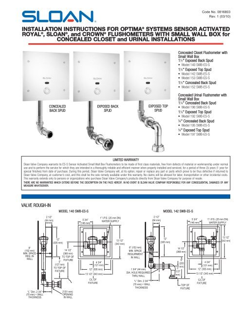
INSTALLATION INSTRUCTIONS FOR OPTIMA ® SYSTEMS SENSOR ACTIVATED<br />
ROYAL ® , SLOAN ® , and CROWN ® FLUSHOMETERS WITH SMALL WALL BOX for<br />
CONCEALED CLOSET and URINAL INSTALLATIONS<br />
Concealed Closet <strong>Flushometer</strong> with<br />
<strong>Small</strong> <strong>Wall</strong> <strong>Box</strong><br />
1½" Exposed Back Spud<br />
• Model 140 SWB-<strong>ES</strong>-S<br />
1½" Exposed Top Spud<br />
• Model 142 SWB-<strong>ES</strong>-S<br />
• Model 153 SWB-<strong>ES</strong>-S<br />
1½" Concealed Back Spud<br />
• Model 152 SWB-<strong>ES</strong>-S<br />
CONCEALED<br />
BACK SPUD<br />
EXPOSED BACK<br />
SPUD<br />
EXPOSED TOP<br />
SPUD<br />
Concealed Urinal <strong>Flushometer</strong> with<br />
<strong>Small</strong> <strong>Wall</strong> <strong>Box</strong><br />
1¼" Concealed Back Spud<br />
• Model 190 SWB-<strong>ES</strong>-S<br />
1¼" Exposed Top Spud<br />
• Model 192 SWB-<strong>ES</strong>-S<br />
¾" Concealed Back Spud<br />
• Model 195 SWB-<strong>ES</strong>-S<br />
¾" Exposed Top Spud<br />
• Model 197 SWB-<strong>ES</strong>-S<br />
LIMITED WARRANTY<br />
<strong>Sloan</strong> <strong>Valve</strong> <strong>Company</strong> warrants its <strong>ES</strong>-S Sensor Activated <strong>Small</strong> <strong>Wall</strong> <strong>Box</strong> <strong>Flushometer</strong>s to be made of first class materials, free from defects of material or workmanship under normal<br />
use and to perform the service for which they are intended in a thoroughly reliable and efficient manner when properly installed and serviced, for a period of three (3) years (1 year for<br />
special finishes) from date of purchase. During this period, <strong>Sloan</strong> <strong>Valve</strong> <strong>Company</strong> will, at its option, repair or replace any part or parts which prove to be thus defective if returned to<br />
<strong>Sloan</strong> <strong>Valve</strong> <strong>Company</strong>, at customer’s cost, and this shall be the sole remedy available under this warranty. No claims will be allowed for labor, transportation or other incidental costs.<br />
This warranty extends only to persons or organizations who purchase <strong>Sloan</strong> <strong>Valve</strong> <strong>Company</strong>’s products directly from <strong>Sloan</strong> <strong>Valve</strong> <strong>Company</strong> for purpose of resale.<br />
THERE ARE NO WARRANTI<strong>ES</strong> WHICH EXTEND BEYOND THE D<strong>ES</strong>CRIPTION ON THE FACE HEREOF. IN NO EVENT IS SLOAN VALVE COMPANY R<strong>ES</strong>PONSIBLE FOR ANY CONSEQUENTIAL DAMAG<strong>ES</strong> OF ANY<br />
MEASURE WHATSOEVER.<br />
VALVE ROUGH-IN<br />
2 1/2” 2 1/2”<br />
(64 mm) (64 mm)<br />
MODEL 140 SWB-<strong>ES</strong>-S<br />
1” I.P.S. 1” (25 I.P.S. mm DN)<br />
5 3/4”<br />
(25 mm DN)<br />
5 3/4” WATER<br />
(146 mm)<br />
WATER SUPPLY SUPPLY<br />
(146 mm)<br />
MODEL 142 SWB-<strong>ES</strong>-S<br />
2 1/2” 2 1/2”<br />
(64 mm)<br />
5 3/4”<br />
(64 mm)<br />
5 3/4” 1” I.P.S. (25 1” I.P.S. mm DN) (25 mm DN)<br />
(146 mm) (146 mm) WATER SUPPLY WATER SUPPLY<br />
12” 12”<br />
(305 mm) (305 mm)<br />
6” 6”<br />
(152 mm) (152 mm)<br />
14 1/2” 14 1/2”<br />
MIN. SPACE MIN. SPACE<br />
(368 mm) (368 mm)<br />
REQ. IN REQ. IN<br />
TO TOP TO OF<br />
WALL<br />
TOP OF<br />
WALL<br />
FIXTURE<br />
5” FIXTURE<br />
5”<br />
4 3/4” 4 3/4”<br />
(127 mm) (127 mm)<br />
(121 mm) (121 mm)<br />
TO TOP TO OF TOP OF<br />
12” (30512” mm)<br />
FIXTURE<br />
(305 mm)<br />
FIXTURE<br />
13 1/2” (343 13 1/2” mm) (343 mm)<br />
C/L OF C/L OF<br />
FIXTURE FIXTURE<br />
“L” Dim. “L” 2 3/4” Dim. 2 3/4” 2”(51 mm) 2”(51 mm)<br />
(70 mm) (70 + WALL mm) + WALL OPENING OPENING<br />
THICKN<strong>ES</strong>S THICKN<strong>ES</strong>S<br />
IN WALLIN WALL<br />
MODEL MODEL 140 140 WB WB <strong>ES</strong>-S <strong>ES</strong>-S<br />
13 1/2” 13 1/2”<br />
(343 mm) (343 mm)<br />
6” (152 mm) 6” (152 mm)<br />
MIN. SPACE MIN. SPACE<br />
REQUIRMENT REQUIRMENT<br />
IN WALLIN WALL<br />
1 3/4” (441 mm) 3/4” (44 mm)<br />
DIA. HOLE DIA. REQUIRED HOLE REQUIRED<br />
THRU WALL THRU WALL<br />
“L” Dim. “L” 2 3/4” Dim. 2 3/4”<br />
(70 mm) (70 + WALL mm) + WALL<br />
THICKN<strong>ES</strong>S THICKN<strong>ES</strong>S<br />
12” 12”<br />
(305 mm) (305 mm)<br />
14 1/2” 14 1/2”<br />
(368 mm) (368 mm)<br />
8”<br />
(203<br />
mm)<br />
5”<br />
(127<br />
mm)<br />
MODEL MODEL 142 142 WB WB <strong>ES</strong>-S <strong>ES</strong>-S<br />
8”<br />
(203<br />
mm)<br />
5”<br />
(127<br />
mm)<br />
4 3/4” 4 3/4”<br />
(121 mm) (121 mm)<br />
12” (30512” mm) (305 mm)<br />
13 1/2” (343 13 1/2” mm) (343 mm)<br />
C/L OF C/L OF<br />
FIXTURE<br />
TOP OF<br />
FIXTURE<br />
TOP OF<br />
FIXTURE FIXTURE<br />
13 1/2” 13 1/2”<br />
(343 mm) (343 mm)<br />
6<br />
M<br />
R
(64 mm) (64 mm)<br />
VALVE ROUGH-IN (Continued)<br />
12” 12”<br />
13 1/2”<br />
12”<br />
13 1/2”<br />
13 1/2”<br />
12”<br />
13 1/2”<br />
2 1/2” (3052 mm) 1/2” (305 mm)<br />
2 1/2” 2 1/2”<br />
(343 mm)<br />
(305 mm)<br />
(343 mm)<br />
(343 mm)<br />
(305 mm)<br />
(343 mm)<br />
(64 mm)<br />
1” I.P.S. (25 mm DN)<br />
(64 mm)<br />
5 3/4” 1” I.P.S. (25 mm DN)<br />
(64 mm)<br />
5 3/4” 1” I.P.S. (25 mm DN)<br />
(64 mm)<br />
5 3/4” 1” I.P.S. (25 mm DN)<br />
6” 6”<br />
5 3/4”<br />
WATER SUPPLY<br />
(146 mm) WATER SUPPLY WATER SUPPLY<br />
6” (152 mm) 6” (152 mm)<br />
(146 mm) (146 mm) WATER SUPPLY<br />
(152 mm)<br />
14 1/2” 14 1/2” (146 mm)<br />
14 1/2” 14 1/2”<br />
(152 mm)<br />
MIN. SPACE MIN. SPACE<br />
6” (152 mm 6”<br />
MIN. SPACE MIN. SPACE<br />
(368 mm) (368 mm)<br />
(368 mm) (368 mm)<br />
REQ. IN<br />
REQUIRMENT<br />
MI<br />
REQ. IN<br />
REQUIRMENT<br />
MIN. SPACE<br />
TO TOP OF TO TOP OF<br />
WALL<br />
IN WALL<br />
WALL<br />
IN WALL<br />
REQUIRMEN<br />
FIXTURE FIXTURE<br />
12” 12”<br />
12” 12”<br />
8”<br />
IN WALLI<br />
5” 5”<br />
8”<br />
4 3/4” 4 3/4”<br />
)<br />
(305 (305<br />
(121 mm) 13 1/2” 13 1/2”<br />
(305 (305<br />
(203<br />
4 3/4” 4 3/4”<br />
(127 mm) (127 mm)<br />
(121 mm)<br />
(203<br />
13 1/2” 13 1/2”<br />
mm) mm)<br />
(343 mm) (343 mm)<br />
mm) mm)<br />
mm)<br />
(121 mm) (121 mm)<br />
TO TOP OF TO TOP OF<br />
mm)<br />
12” (305 mm) 12” (305 mm)<br />
(343 mm) (343 mm)<br />
1 3/4” (44 mm)<br />
5”<br />
FIXTURE<br />
1 3/4” (44 mm)<br />
5”<br />
FIXTURE<br />
12” (305 mm) 12” (305 mm)<br />
6” (152 mm) 6” (152 mm)<br />
6” (152 mm) 6” (152 mm)<br />
13 1/2” (343 mm)<br />
DIA. HOLE REQUIRED<br />
(127<br />
13 1/2” (343 mm)<br />
DIA. HOLE REQUIRED<br />
(127<br />
MIN. SPACE MIN. THRU SPACE WALL<br />
14 1/2” mm)<br />
13 1/2” (343 mm)<br />
THRU WALL<br />
mm)<br />
13 1/2” (343 mm)<br />
14 1/2”<br />
MIN. SPACE MIN. SPACE<br />
C/L OF C/L OF<br />
REQUIRMENT REQUIRMENT<br />
(368 mm) (368 mm)<br />
REQUIRMENT REQUIRMENT<br />
14 1/2” 14 1/2”<br />
IN WALL IN “L” WALL Dim. 2 3/4”<br />
C/L OF<br />
FIXTURE<br />
“L” Dim. 2 3/4”<br />
C/L OF<br />
FIXTURE<br />
IN WALL IN WALL<br />
(368 mm) (368 mm)<br />
(70 mm) + (70 WALL mm) + WALL<br />
FIXTURE FIXTURE<br />
TOP OF TOP OF<br />
8” 8”<br />
8” 8”<br />
4 3/4” 4 3/4”<br />
THICKN<strong>ES</strong>S THICKN<strong>ES</strong>S<br />
4 3/4” 4 3/4”<br />
FIXTURE FIXTURE<br />
“L” Dim<br />
“L” Dim. 2 “L” 3/4” Dim. 2 3/4” (203 mm) 2”(51 (203 mm) 2”(51 mm)<br />
(203 (203<br />
(121 mm) (121 mm)<br />
(121 mm) (121 mm)<br />
(70 mm)<br />
(70 mm) + (70 WALL mm) + WALL TO TOP OF TO OPENING TOP OF OPENING<br />
5” mm) 5” mm)<br />
12” (305 mm)<br />
12” (305 mm) 12” (305 mm)<br />
12” (305 mm)<br />
THICKN<strong>ES</strong>S<br />
1 3/4” (441 mm) 3/4” (44 mm)<br />
THICK<br />
THICKN<strong>ES</strong>S FIXTURE FIXTURE IN WALLIN WALL<br />
(127 (127<br />
13 1/2” (343 13 mm) 1/2” (343 mm)<br />
DIA. HOLE DIA. REQUIRED HOLE REQUIRED mm) mm)<br />
13 1/2” (343 13 mm) 1/2” (343 mm)<br />
MODEL THRU WALL MODEL THRU WALL 142 142 WB <strong>ES</strong>-S WB <strong>ES</strong>-S<br />
MO<br />
C/L OF C/L OF<br />
C/L OF C/L OF<br />
MODEL MODEL<br />
2 1/2”<br />
2 1/2”<br />
140 140 WB <strong>ES</strong>-S WB <strong>ES</strong>-S<br />
FIXTURE<br />
FIXTURE FIXTURE<br />
“L” Dim. 2 “L” 3/4” Dim. 2 3/4”<br />
FIXTURE<br />
2 1/2”<br />
2 1/2”<br />
(64 mm)<br />
1” I.P.S. (25 mm DN)<br />
(64 mm)<br />
5 3/4” 1” I.P.S. (25 mm DN)<br />
5 3/4”<br />
TOP OF TOP OF<br />
1” I.P.S. (25 mm DN)<br />
“L” Dim. 2 “L” 3/4” Dim. 2 3/4” (64 mm)<br />
5 3/4” 1” I.P.S. (25 mm DN)<br />
(70 mm) + (70 WALL mm) + (64 WALL mm)<br />
5 3/4”<br />
WATER SUPPLY<br />
(146 mm) WATER SUPPLY<br />
(146 mm)<br />
FIXTURE FIXTURE<br />
WATER SUPPLY<br />
(70 mm) + (70 WALL mm) + WALL<br />
(146 mm) WATER SUPPLY<br />
THICKN<strong>ES</strong>S THICKN<strong>ES</strong>S<br />
(146 mm)<br />
THICKN<strong>ES</strong>S THICKN<strong>ES</strong>S<br />
MODEL MODEL 152 WB 152 12” <strong>ES</strong>-S WB <strong>ES</strong>-S<br />
MODEL 152 SWB-<strong>ES</strong>-S<br />
12”<br />
MODEL MODEL 195 WB 195 <strong>ES</strong>-S WB 12” <strong>ES</strong>-S<br />
1” I.P.S. (25 1” I.P.S. mm DN) (25 mm DN)<br />
5 3/4” 5 3/4”<br />
WATER SUPPLY WATER SUPPLY<br />
(146 mm) (146 mm)<br />
MODEL 190 SWB-<strong>ES</strong>-S<br />
2<br />
2 1/2” 2 1/2”<br />
(64 mm) (64 mm)<br />
MODEL 153 SWB-<strong>ES</strong>-S<br />
12”<br />
MODEL MODEL 153 WB 153 <strong>ES</strong>-S WB <strong>ES</strong>-S<br />
MODEL 192 SWB-<strong>ES</strong>-S<br />
”<br />
12”<br />
12”<br />
(305<br />
13 1/2”<br />
(305<br />
13 1/2”<br />
2 1/2”<br />
m)<br />
2 1/2” 2 1/2” (305<br />
13 1/2”<br />
2 1/2”<br />
(305<br />
13 1/2”<br />
mm)<br />
(343 mm)<br />
mm)<br />
(64 mm)<br />
1” I.P.S. (25 mm DN)<br />
(64 mm) (64 mm)<br />
5 3/4” 1” I.P.S. (25 1” I.P.S. mm (343 DN) (25 mm)<br />
DN)<br />
(64 mm) mm)<br />
(343 mm)<br />
mm)<br />
5 3/4”<br />
1” I.P.S. (25 mm DN)<br />
(343 mm)<br />
5 3/4” 5 3/4”<br />
6” (152 mm)<br />
(146 mm) (146 mm) WATER SUPPLY WATER SUPPLY<br />
6” (152 mm)<br />
(146 mm) (146 mm) WATER SUPPLY WATER SUPPLY MIN. SPACE 6” (152 mm)<br />
14 1/2”<br />
MIN. SPACE 6” (152 mm)<br />
REQUIRMENT MIN. SPACE<br />
(368 mm) 14 1/2”<br />
REQUIRMENT MIN. SPACE<br />
14 1/2”<br />
IN WALL REQUIRMENT<br />
(368 mm)<br />
IN WALL REQUIRMENT<br />
(368 mm) 14 1/2”<br />
IN WALL<br />
IN WALL<br />
2 1/2” 12” 8”<br />
2 1/2” 12” (368 mm)<br />
8”<br />
4 3/4”<br />
4 3/4”<br />
12” 12”<br />
13 1/2” 13 1/2”<br />
13 1/2” 13 1/2”<br />
8”<br />
(64 mm) (305 (64 mm) (305<br />
4 3/4”<br />
4 3/4”<br />
(203 mm) 8”<br />
(203<br />
(121 3/4” I.P.S. (20 mm DN)<br />
2 1/2” 2 1/2”<br />
5 3/4”<br />
3/4” mm)<br />
(121 mm)<br />
I.P.S. (20 mm DN)<br />
(305 (305<br />
(343 mm) (343 mm)<br />
5 3/4”<br />
(343 mm) (343 mm)<br />
(203<br />
TO<br />
mm)<br />
TOP OF (203 mm)<br />
mm)<br />
(121 mm)<br />
5” mm)<br />
WATER SUPPLY<br />
(64 mm) (64 mm)<br />
5 3/4” 3/4” I.P.S.<br />
(121<br />
3/4” (20<br />
mm)<br />
I.P.S. mm DN) (20 mm DN)<br />
(146 mm) (146 mm)<br />
WATER SUPPLY<br />
mm) mm) 5” 5 3/4” 12” (305 mm)<br />
TO TOP OF<br />
12” (305 mm)<br />
1 3/4” (44 mm)<br />
mm)<br />
FIXTURE<br />
(127<br />
(146 mm) (146 mm) WATER 12” (305 SUPPLY WATER mm) SUPPLY<br />
6” (152 mm) 6” (152 mm)<br />
12” (305 mm)<br />
6” (152 mm) 6” (152 1 3/4” mm) (44 mm)<br />
6” (152<br />
FIXTURE<br />
13 1/2” (343 mm)<br />
DIA. HOLE REQUIRED<br />
mm) (127 13 1/2” (343 mm)<br />
MIN. SPACE<br />
MIN. SPACE MIN. SPACE<br />
18 1/2”<br />
MIN. SP<br />
MIN. SPACE<br />
13 1/2” (343 mm)<br />
DIA. HOLE REQUIRED<br />
18 1/2” mm)<br />
13 1/2” (343 mm)<br />
THRU WALL<br />
REQUIRMENT REQUIRMENT<br />
REQUIRMENT REQUIRMENT THRU WALL<br />
(470 mm) (470 mm) C/L OF<br />
REQUIR<br />
14 1/2” 14 1/2” C/L OF<br />
IN WALLIN WALL<br />
C/L OF<br />
IN WALLIN WALL<br />
FIXTURE C/L OF<br />
IN WA<br />
12” (36812”<br />
mm) (368 mm) FIXTURE<br />
“L” Dim. 2 3/4”<br />
5” 5”<br />
FIXTURE<br />
“L” Dim. 2 3/4” TOP OF<br />
FIXTURE<br />
“L” Dim. 2 3/4”<br />
(70 mm) + WALL<br />
(305 mm) (305 mm)<br />
4 3/4” 4 3/4” 13 1/2” 13 1/2”<br />
8” 8”<br />
4 3/4” 4 3/4”<br />
12” 12”<br />
13 1/2” 13 1/2”<br />
)<br />
“L” Dim. 2 3/4” (127 mm) (127 mm)<br />
(70 mm) + WALL FIXTURETOP OF<br />
(70 mm) + WALL<br />
THICKN<strong>ES</strong>S<br />
(121 mm) (343 mm) (343 mm)<br />
(203<br />
(121 mm)<br />
(305 mm) (305 mm)<br />
(343 mm) (343 mm)<br />
TO TOP OF<br />
(121 mm)<br />
(203 FIXTURE (121 mm)<br />
(70 mm) + WALL TO TOP OF<br />
THICKN<strong>ES</strong>S<br />
THICKN<strong>ES</strong>S<br />
5” mm) 5” mm)<br />
12” (305 mm)<br />
6” (152 mm) 6” (152 mm)<br />
FIXTURE<br />
12” (305 mm)<br />
THICKN<strong>ES</strong>S FIXTURE<br />
12” (305 mm) 12” (305 mm)<br />
1<br />
18 1/2” 18 1/2”<br />
6”<br />
3/4”<br />
(152<br />
(44<br />
mm)<br />
1<br />
6”<br />
mm) 3/4”<br />
(152<br />
(44<br />
mm)<br />
mm)<br />
(127 (127<br />
MIN. SPACE MIN. SPACE<br />
18 1/2” 18 1/2”<br />
(470 mm) (470 mm)<br />
13 1/2” (343 mm)<br />
MIN.<br />
DIA.<br />
SPACE<br />
HOLE<br />
MIN. SPACE<br />
REQUIRED<br />
mm)<br />
13 1/2” (343 mm)<br />
13 1/2” (343 mm)<br />
DIA. HOLE REQUIRED<br />
mm)<br />
13 1/2” (343 mm)<br />
REQUIRMENT<br />
MODEL<br />
REQUIRMENT<br />
(470 mm) (470 mm)<br />
REQUIRMENT<br />
THRU WALL<br />
REQUIRMENT<br />
THRU WALL<br />
1” (25 m<br />
MODEL<br />
152<br />
152<br />
WB <strong>ES</strong>-S<br />
MODEL<br />
WB <strong>ES</strong>-S<br />
MODEL<br />
153<br />
153<br />
WB <strong>ES</strong>-S<br />
WB <strong>ES</strong>-S C/L OF C/L OF<br />
IN WALL IN WALL<br />
DIA. HOLE DIA. R<br />
IN WALL IN WALL<br />
FIXTURE FIXTURE<br />
5” 5”<br />
4 3/4” 4 3/4”<br />
“L” Dim. 2 3/4” (70 mm)<br />
“L” Dim. 2 3/4”<br />
“L” Dim. 2 3/4” (70 mm)<br />
THRU W<br />
“L” Dim. 2 3/4”<br />
TOP OF TOP OF<br />
(127 mm) (127 mm)<br />
4 3/4”<br />
(121 mm)<br />
8”<br />
4 3/4”<br />
(121 mm)<br />
+ WALL THICKN<strong>ES</strong>S 8”<br />
(70 mm) + WALL<br />
+ WALL THICKN<strong>ES</strong>S<br />
(70 mm) + WALL<br />
FIXTURE FIXTURE<br />
TO TOP OF TO TOP OF<br />
(203 (203 (121 mm) (121 mm)<br />
THICKN<strong>ES</strong>S THICKN<strong>ES</strong>S<br />
FIXTURE FIXTURE<br />
12” (305 mm) 12” (305 mm)<br />
1” (25 mm) 1” DIA. (25 mm) DIA.<br />
5” 5”<br />
mm) mm) 12” (305 mm) 12” (305 mm)<br />
13 1/2” (343 13 mm) 1/2” (343 mm)<br />
HOLE REQUIRED HOLE REQUIRED (127 (127<br />
13 1/2” (343 mm)<br />
THRU WALL<br />
mm) 13 1/2” (343 mm)<br />
THRU WALL<br />
mm)<br />
MODEL MODEL 190 190 WB <strong>ES</strong>-S WB MODEL <strong>ES</strong>-S 195 SWB-<strong>ES</strong>-S<br />
1” (25 mm) 1” (25 mm)<br />
C/L OF C/L OF<br />
MODEL MODEL 192 192 WB MODEL <strong>ES</strong>-S WB 197 SWB-<strong>ES</strong>-S<br />
M<br />
2 1/2”<br />
C/L OF C/L OF<br />
DIA. HOLE DIA. REQUIRED HOLE REQUIRED<br />
(64 mm) 2 1/2”<br />
FIXTURE3/4” FIXTURE I.P.S. (20 mm DN)<br />
2 1/2”<br />
THRU WALL THRU WALL<br />
5 3/4”<br />
2 1/2”<br />
FIXTURE FIXTURE<br />
(64 mm)<br />
5 3/4” WATER 3/4” SUPPLY I.P.S. (20 mm DN)<br />
“L” Dim. 2 “L” 3/4” Dim. (70 (642 mm) mm)<br />
5 3/4” 3/4” I.P.S. (20 mm DN)<br />
(146 mm)<br />
3/4” (70 mm)<br />
WATER SUPPLY<br />
(64 mm) TOP OF TOP OF 5 3/4” WATER 3/4” SUPPLY I.P.S. (20 mm DN)<br />
(146 mm)<br />
“L” Dim. 2 “L” 3/4” Dim. 2 3/4”<br />
(146 mm)<br />
+ WALL THICKN<strong>ES</strong>S + WALL THICKN<strong>ES</strong>S FIXTURE FIXTURE (146 mm) WATER SUPPLY<br />
(70 mm) + (70 WALL mm) + WALL<br />
THICKN<strong>ES</strong>S THICKN<strong>ES</strong>S<br />
”<br />
m)<br />
6” (152 mm)<br />
MIN. SPACE 6” (152 mm)<br />
REQUIRMENT MIN. SPACE<br />
IN WALL REQUIRMENT<br />
IN WALL<br />
1” (25 mm)<br />
DIA. HOLE REQUIRED 1” (25 mm)<br />
THRU DIA. WALL HOLE REQUIRED<br />
THRU WALL<br />
“L” Dim. 2 3/4”<br />
(70 mm) + “L” WALL Dim. 2 3/4”<br />
THICKN<strong>ES</strong>S (70 mm) + WALL<br />
THICKN<strong>ES</strong>S<br />
(305 mm)<br />
(305 mm)<br />
18 1/2”<br />
(470 mm) 18 1/2”<br />
(470 mm)<br />
5”<br />
(127 mm) 5”<br />
TO TOP OF (127 mm)<br />
FIXTURE TO TOP OF<br />
FIXTURE<br />
MODEL<br />
MODEL<br />
195<br />
195<br />
WB <strong>ES</strong>-S<br />
WB <strong>ES</strong>-S<br />
4 3/4”<br />
(121 mm) 4 3/4”<br />
(121 mm)<br />
12” (305 mm)<br />
12” (305 mm)<br />
13 1/2” (343 mm)<br />
13 1/2” (343 mm)<br />
C/L OF<br />
FIXTURE C/L OF<br />
FIXTURE<br />
13 1/2”<br />
(343 mm) 13 1/2”<br />
(343 mm)<br />
MODEL MODEL 197 WB 197 <strong>ES</strong>-S WB <strong>ES</strong>-S<br />
MODEL<br />
MODEL<br />
197<br />
197<br />
WB <strong>ES</strong>-S<br />
WB <strong>ES</strong>-S<br />
5 3/4” 5 3/4” 1” I.P.S. (25 1” I.P.S. mm DN) (25 mm DN)<br />
(146 mm) (146 mm) WATER SUPPLY WATER SUPPLY<br />
12”<br />
13 1/2”<br />
13 1/2”<br />
(305 mm) 12”<br />
(343 mm)<br />
(305 mm)<br />
(343 mm)<br />
6” (152 mm)<br />
6” (152 mm)<br />
18 1/2”<br />
MIN. SPACE<br />
MIN. SPACE<br />
(470 mm) 18 1/2”<br />
REQUIRMENT<br />
(470 mm)<br />
IN WALL REQUIRMENT<br />
IN WALL<br />
8”<br />
4 3/4”<br />
(203 8”<br />
(121 mm) 4 3/4”<br />
1” (25 mm) DIA.<br />
5”<br />
mm) (203<br />
(121 mm)<br />
1” (25 mm) DIA.<br />
5”<br />
12” (305 mm)<br />
HOLE REQUIRED<br />
(127 mm)<br />
12” (305 mm)<br />
HOLE REQUIRED<br />
(127 13 1/2” (343 mm)<br />
THRU WALL<br />
mm)<br />
13 1/2” (343 mm)<br />
THRU WALL<br />
mm)<br />
C/L OF<br />
FIXTURE C/L OF<br />
“L” Dim. 2 3/4” (70 mm)<br />
TOP OF<br />
FIXTURE<br />
+ WALL “L” THICKN<strong>ES</strong>S Dim. 2 3/4” (70 mm)<br />
FIXTURETOP OF<br />
+ WALL THICKN<strong>ES</strong>S<br />
FIXTURE<br />
SMALL WALL BOX/SENSOR LOCATION & POSITIONING IS CRITICAL!<br />
Failure to properly position the small wall box/sensor to the plumbing rough-in will result in improper installation and impair product performance. All tradesmen<br />
(plumbers, electricians, tile setters, etc.) involved with the installation of this product must coordinate their work to assure proper product installation.
PRIOR TO INSTALLATION<br />
Check to make certain that “L” dimension shown on the <strong>Flushometer</strong><br />
package is correct for your application (Lengths of 2” up to 10¾”).<br />
Determine the “L” dimension for your application by using the<br />
following formula:<br />
“L” dimension = <strong>Wall</strong> Thickness (To Nearest Whole Inch) + 2-3/4"<br />
Prior to installing the <strong>Sloan</strong> OPTIMA equipped <strong>Flushometer</strong> with <strong>Small</strong> <strong>Wall</strong><br />
<strong>Box</strong>, install the items listed below. Refer to Rough-ins on the front page and<br />
page 2.<br />
• 2-gang electrical box — 4" x 4" x 2-1/2" (102 mm x 102 mm x 64 mm)<br />
for transformer; see paragraph entitled “Transformer Installation”<br />
• Electrical wiring to the transformer box (120 VAC, 2 amp service required<br />
for each EL-154, 24 VAC, 50 VA transformer used)<br />
• Closet or urinal fixture<br />
• Drain line<br />
• Water supply line<br />
Important:<br />
• INSTALL ALL ELECTRICAL WIRING IN ACCORDANCE WITH NATIONAL/<br />
LOCAL COD<strong>ES</strong> AND REGULATIONS.<br />
• INSTALL ALL PLUMBING IN ACCORDANCE WITH APPLICABLE COD<strong>ES</strong><br />
AND REGULATIONS.<br />
• WATER SUPPLY LIN<strong>ES</strong> MUST BE SIZED TO PROVIDE AN ADEQUATE<br />
VOLUME OF WATER FOR EACH FIXTURE.<br />
• A 24 VAC STEP-DOWN TRANSFORMER MUST BE USED.<br />
• USE APPROPRIATE PRECAUTIONS WHILE CONNECTING TRANSFORMER<br />
TO 120 VAC POWER SOURCE.<br />
• FLUSH ALL WATER LIN<strong>ES</strong> PRIOR TO MAKING CONNECTIONS.<br />
Royal ® , <strong>Sloan</strong> ® , and Crown ® <strong>Flushometer</strong>s are designed to operate with 15<br />
to 100 psi (104 to 689 kPa) of water pressure. THE MINIMUM PR<strong>ES</strong>SURE<br />
REQUIRED TO THE VALVE IS DETERMINED BY THE TYPE OF FIXTURE<br />
SELECTED. Consult fixture manufacturer for minimum pressure<br />
requirements. Most Low Consumption water closets (1.6 gallon/6.0 liter)<br />
require a minimum flowing pressure of 25 psi (172 kPa).<br />
Protect the Chrome or Special finish of the <strong>Flushometer</strong> — DO NOT USE<br />
TOOTHED TOOLS TO INSTALL OR SERVICE THE VALVE. Also, see "Care and<br />
Cleaning" section of this manual. Important: EXCEPT FOR CONTROL STOP<br />
INLET, DO NOT USE PIPE SEALANT OR PLUMBING GREASE ON ANY VALVE<br />
COMPONENT OR COUPLING!<br />
!!! IMPORTANT !!!<br />
With the exception of Control Stop Inlet, DO NOT use pipe sealant or<br />
plumbing grease on any valve component or coupling!<br />
!!! IMPORTANT !!!<br />
This product contains mechanical and/or electrical components that are<br />
subject to normal wear. These components should be checked on a regular<br />
basis and replaced as needed to maintain the valve’s performance.<br />
Transformer Installation<br />
2-GANG ELECTRICAL BOX -<br />
4" x 4" x 2½" (102 mm x 102 mm x 64 mm)<br />
EL-154 TRANSFORMER †<br />
† MOUNT TRANSFORMER<br />
WITHIN 50 FEET (15 m) OF<br />
FLUSHOMETER<br />
Install Transformer (EL-154) on a 2-Gang Electrical <strong>Box</strong>, 4" x 4" x 2-1/2"<br />
(102 mm x 102 mm x 64 mm) in a convenient location; refer to the<br />
illustration below. Note: One <strong>Sloan</strong> EL-154 transformer (Class 2, UL Listed,<br />
50 VA (min.) at 24 VAC) can operate up to ten OPTIMA equipped<br />
<strong>Flushometer</strong>s. Run 18-gauge wire from transformer to <strong>Flushometer</strong>(s). Wire<br />
supplied by others. DO NOT supply power to transformer until installation of<br />
<strong>Flushometer</strong> is complete.<br />
<strong>Small</strong> <strong>Wall</strong> <strong>Box</strong>/Sensor Location<br />
SMALL WALL BOX/SENSOR LOCATION IS CRITICAL — Failure to properly<br />
position the <strong>Wall</strong> <strong>Box</strong> to the plumbing rough-in will result in improper<br />
installation and impair product performance. All tradesmen (plumbers,<br />
electricians, tile setters, etc.) involved with the installation of this sensor<br />
activated flushometer must be familiar with the requirements of its<br />
installation. Improper installation may void the manufacturer's warranty.<br />
Tools Required for Installation<br />
• Slotted and Phillips screwdrivers • Channel lock ® plier or<br />
• 5/64" hex wrench (supplied)<br />
adjustable wrench<br />
• Wrench for tamper resistant • Wire stripper/crimping tool<br />
screws (supplied)<br />
• <strong>Sloan</strong> A-50 Super-Wrench or smooth jawed spud wrench<br />
!!! IMPORTANT !!!<br />
Protect the chrome or special finish of <strong>Sloan</strong> <strong>Flushometer</strong>s — DO NOT USE<br />
toothed tools to install or service these valves. Use a <strong>Sloan</strong> A-50 Super-<br />
Wrench, <strong>Sloan</strong> A-109 Plier Wrench or smooth jawed spud wrench to<br />
secure all couplings. Also see “Care and Cleaning” section of this manual.<br />
!!! IMPORTANT !!!<br />
Never open Control Stop to where the flow from the valve exceeds the flow<br />
capability of the fixture. In the event of a valve failure, the fixture must be<br />
able to accommodate a continuous flow from the valve.<br />
1 - INSTALL WALL BOX INTO WALL AND INSTALL OPTIONAL<br />
SWEAT SOLDER ADAPTER (only if your supply pipe does not<br />
have a male thread)<br />
A<br />
Install <strong>Wall</strong> <strong>Box</strong> flush with <strong>Wall</strong>. Secure using Fasteners.<br />
Note: Fasteners supplied by installer.<br />
FASTENER HOL<strong>ES</strong><br />
(12 TOTAL)<br />
B Slide Threaded Adapter fully onto pipe.<br />
C<br />
Sweat solder the Adapter to pipe.<br />
SWEAT<br />
SOLDER<br />
ADAPTER<br />
WALL BOX<br />
3<br />
WATER SUPPLY PIPE
2152<br />
- INSTALL 153 CONTROL 190 STOP 192TO SUPPLY 195 PIPE 197<br />
A<br />
Thread Control Stop onto water supply line. Tighten with a wrench<br />
making sure outlet is positioned as required.<br />
BAK-CHEK ®<br />
CONTROL STOP<br />
!!! IMPORTANT !!!<br />
With the exception of Control Stop Inlet, DO NOT use pipe sealant or<br />
plumbing grease on any valve component or coupling!<br />
IRON PIPE NIPPLE OR<br />
COPPER PIPE WITH SWEAT<br />
SOLDER ADAPTER<br />
3 - INSTALL VACUUM BREAKER FLUSH CONNECTION<br />
A<br />
B<br />
Assemble Pipe, Elbows, Couplings, Nylon Slip Gasket, Rubber<br />
Gaskets and Flanges as illustrated.<br />
Insert Tube into Fixture Spud.<br />
1-1/4” (32 mm) MIN.<br />
C<br />
VACUUM<br />
BREAKER<br />
TUBE<br />
Hand tighten all Couplings.<br />
MODEL<br />
MODEL MODEL MODEL<br />
140 140 WB-<strong>ES</strong>-S 142 142 WB-<strong>ES</strong>-S 152 152 WB-<strong>ES</strong>-S 153 153 WB-<strong>ES</strong>-S<br />
COUPLING<br />
NYLON<br />
SLIP<br />
GASKET<br />
IMPORTANT: WHEN CUTTING SCORED PIPE TO LENGTH<br />
LEAVE A MINIMUM OF 1-1/4” (32 mm) OF SCORING TO<br />
ENSURE PROPER ENGAGEMENT<br />
MODEL MODEL<br />
MODEL MODEL<br />
190 190 WB-<strong>ES</strong>-S 192 192 WB-<strong>ES</strong>-S<br />
195 WB-<strong>ES</strong>-S 195 197 197 WB-<strong>ES</strong>-S<br />
RUBBER<br />
GASKET<br />
ELBOW<br />
SPUD<br />
COUPLING<br />
SPUD<br />
FLANGE<br />
INSTALL<br />
WITH<br />
FLANGE<br />
AGAINST<br />
SPUD<br />
4 - INSTALL FLUSHOMETER<br />
A<br />
B<br />
C<br />
Lubricate tailpiece O-ring with water. Insert Adjustable Tailpiece into<br />
Control Stop. Tighten Tailpiece Coupling by hand.<br />
Align <strong>Flushometer</strong> directly above the Vacuum Breaker Flush<br />
Connection by sliding the <strong>Flushometer</strong> Body IN or OUT as needed.<br />
Tighten Vacuum Breaker Coupling by hand.<br />
Align <strong>Flushometer</strong> Body and securely tighten first the Tailpiece<br />
Coupling (1), then the Vacuum Breaker and Pipe Couplings (2), and<br />
finally the Spud Coupling (3). Use a wrench to tighten these<br />
couplings in the order shown.<br />
NOTE<br />
Max. adjustment of <strong>Sloan</strong> Adjustable Tailpiece is ½" (13 mm) IN or OUT<br />
from the standard 4¾" (121 mm) (c/l of <strong>Valve</strong> to c/l of Control Stop).<br />
If roughing-in measurement exceeds 5¼” (133 mm), consult factory for<br />
longer tailpiece.<br />
4<br />
FLUSHOMETER<br />
BODY<br />
G-44 FRICTION<br />
RING<br />
VACUUM BREAKER<br />
COUPLING<br />
2<br />
VACUUM BREAKER<br />
FLUSH CONNECTION<br />
2<br />
PIPE COUPLINGS<br />
C/L FIXTURE<br />
1<br />
TAILPIECE<br />
COUPLING<br />
O-RING<br />
ADJUSTABLE<br />
TAILPIECE<br />
VACUUM<br />
BREAKER<br />
REPAIR KIT<br />
3<br />
SPUD<br />
COUPLING<br />
C/L SUPPLY<br />
4-3/4"<br />
(121 mm)<br />
+/- 1/2”<br />
(13 mm)<br />
CONTROL STOP
5 - INSTALL U-TYPE NUTS ONTO FRAME AND CONNECT<br />
ELECTRICAL COMPONENTS<br />
A<br />
Slide four (4) U-type Nuts onto frame at each hole location as<br />
shown.<br />
E<br />
Connect the two BLACK wires from the Circuit Board to the<br />
Solenoid wires using wire nuts (supplied by others).<br />
F<br />
Connect the two wires from the Transformer to the BLUE Terminal<br />
Block.<br />
OVERRIDE<br />
BUTTON<br />
SENSOR<br />
Connect Wires<br />
from<br />
Transformer to<br />
TERMINAL<br />
BLOCK<br />
CIRCUIT<br />
BOARD<br />
YELLOW<br />
WIR<strong>ES</strong><br />
ACC<strong>ES</strong>S<br />
PANEL<br />
RED<br />
WIR<strong>ES</strong><br />
U-TYPE NUTS (4)<br />
B<br />
C<br />
D<br />
Be certain power is OFF to prevent damage to electrical<br />
components. Connect wires EXACTLY as instructed and shown.<br />
On the wall plate assembly, connect the two YELLOW wires from<br />
the Circuit Board to the Override Button.<br />
Connect the two RED wires from the Circuit Board to the Sensor.<br />
SOLENOID<br />
VALVE<br />
BLACK<br />
WIR<strong>ES</strong><br />
WIRE NUT<br />
6 - FLUSH OUT SUPPLY LINE<br />
A<br />
Make sure Control Stop is CLOSED.<br />
A<br />
B<br />
C<br />
B<br />
C<br />
D<br />
Remove <strong>Flushometer</strong> Cover and lift out Inside Parts Assembly. Reinstall<br />
<strong>Flushometer</strong> Cover wrench tight.<br />
Open Control Stop. Turn on water supply to flush line of any debris<br />
or sediment.<br />
Shut off Control Stop, remove Cover and reinstall Inside Parts Assembly.<br />
Install <strong>Flushometer</strong> Cover wrench tight. Do Not Open Control Stop until<br />
Step 7.<br />
5<br />
D
7 - TURN WATER ON AND ADJUST CONTROL STOP<br />
A<br />
Adjust Control Stop to meet the flow rate required for proper<br />
cleansing of the fixture. Open Control Stop COUNTERCLOCKWISE<br />
1/2 turn from the closed position.<br />
C<br />
Adjust Control Stop after each flush until the rate of flow delivered<br />
properly cleanses the fixture.<br />
B<br />
Activate <strong>Flushometer</strong> by placing hand in front of OPTIMA Sensor<br />
Lens for ten (10) seconds and then moving it away.<br />
!!! IMPORTANT !!!<br />
All <strong>Sloan</strong> ® <strong>Flushometer</strong>s are engineered for quiet operation. Excessive water<br />
flow creates noise, while too little water flow may not satisfy the needs of the<br />
fixture. Proper adjustment is made when plumbing fixture is cleansed after<br />
each flush without splashing water out from the lip AND a quiet flushing<br />
cycle is achieved.<br />
Never open Control Stop to where the flow from the valve exceeds the flow<br />
capability of the fixture. In the event of a valve failure, the fixture must be<br />
able to accommodate a continuous flow from the valve.<br />
8 - INSTALL ACC<strong>ES</strong>S PANEL AND T<strong>ES</strong>T SENSOR OPERATION<br />
A<br />
Slide access panel over the wall box aligning the four (4) mounting<br />
holes.<br />
D<br />
For the first ten (10) minutes of operation, a Visible Light flashes in the<br />
Sensing Window of the <strong>Flushometer</strong> when a user is detected.<br />
B<br />
Install the four (4) fasteners into the four (4) mounting holes.<br />
E<br />
Stand in front of Sensor for ten (10) seconds.<br />
C<br />
Turn the power ON.<br />
F<br />
Step away from Sensor and listen for “CLICK.”<br />
B<br />
The <strong>Optima</strong> ® sensor has a factory set sensing range:<br />
Water Closets: 22” to 42” (559 mm to 1067 mm)<br />
Urinals: 15” to 30” (381 mm to 762 mm)<br />
NOTE<br />
The factory setting should be satisfactoy for most installations.<br />
OPERATION<br />
1. A continuous,<br />
invisible light beam<br />
is emitted from the<br />
OPTIMA Sensor.<br />
2. When a user enters the<br />
beam’s effective range,<br />
for water closets 22” -<br />
42” (559 mm - 1067<br />
mm) and for urinals 15” -<br />
30” (381 mm - 762 mm),<br />
the beam is reflected into<br />
the OPTIMA’s scanning<br />
window and transformed<br />
into a low voltage<br />
electrical signal that<br />
activates a ten-second<br />
time delay circuit. The<br />
time delay circuit<br />
eliminates false operation<br />
from passers-by in the<br />
rest room. Once the time<br />
delay is completed, the<br />
output circuit is alerted<br />
and continues in a “hold”<br />
mode for as long as the<br />
user remains within the<br />
effective range of<br />
the sensor.<br />
3. When the user steps away<br />
from the OPTIMA Sensor,<br />
the loss of reflected light<br />
initiates an electrical<br />
“one-time” signal that<br />
energizes the Solenoid<br />
Operator, and activates<br />
the <strong>Flushometer</strong> to flush<br />
the fixture. This occurs on<br />
the water closet<br />
approximately three (3)<br />
seconds after indication.<br />
This delay is built into the<br />
Sensor to help prevent<br />
false flushing due to<br />
movement by the user.<br />
The circuit for both water<br />
closets and urinals then<br />
automatically resets and is<br />
ready for the next user.<br />
6
CARE AND CLEANING<br />
DO NOT use abrasive or chemical cleaners (including chlorine bleach) to clean<br />
<strong>Flushometer</strong>s as they may dull the luster and attack the chrome or special<br />
decorative finishes. Use ONLY soap and water, then wipe dry with clean cloth<br />
or towel.<br />
While cleaning the bathroom tile, the <strong>Flushometer</strong> should be protected from<br />
any splattering of cleaner. Acids and cleaning fluids can discolor or remove<br />
chrome plating.<br />
TROUBL<strong>ES</strong>HOOTING GUIDE<br />
NOTE: Upon detection of the user, the red indicator light flashes slowly for a period of eight seconds. When the user leaves the detection range, the indicator<br />
light flashes rapidly and the Sensor initiates the flush sequence. Then the indicator light stops flashing and the valve flushes. The valve will flush after a threesecond<br />
delay.<br />
1. PROBLEM: <strong>Valve</strong> does not function (red light does not flash when user<br />
steps in front of sensor).<br />
CAUSE: No power is being supplied to sensor.<br />
SOLUTION: Ensure that the main power is turned “ON.” Check<br />
transformer, leads and connections. Repair or replace as<br />
necessary.<br />
CAUSE: EL-1500 (Urinal installations) or EL-1500-L (Closet<br />
installations) Sensor is not operating.<br />
SOLUTION: Replace EL-1500 or EL-1500-L Sensor.<br />
2. PROBLEM: <strong>Valve</strong> does not function (red light flashes when user steps in<br />
front of Sensor).<br />
INDICATOR: Red light stops flashing when user steps away and valve<br />
makes a “clicking” sound but does not flush.<br />
CAUSE: No water is being supplied to the valve.<br />
SOLUTION: Make certain that water supply is turned “ON” and the Control<br />
Stop is open.<br />
CAUSE: EL-128-A cartridge is fouled or jammed.<br />
SOLUTION: Turn electronic power to valve “OFF” (failure to do so could<br />
result in damage to the solenoid coil). Remove the solenoid<br />
operator from the valve and remove the<br />
EL-128-A cartridge. Clean and/or repair as necessary.<br />
INDICATOR: The red light stops flashing when user steps away but the<br />
valve does NOT make a “clicking” sound and does NOT flush.<br />
CAUSE: EL-163-A solenoid shaft assembly is fouled or jammed.<br />
SOLUTION: Turn electronic power to valve “OFF” (failure to do so could<br />
result in damage to the solenoid coil). Remove<br />
EL-101 or EL-166 nut from the solenoid operator. Remove the<br />
coil from the solenoid operator. Use a spanner wrench or pliers<br />
to remove the EL-163-A solenoid shaft assembly from valve.<br />
Clean and/or replace as necessary. Be sure to replace plunger<br />
spring when reassembling Solenoid Shaft Assembly.<br />
INDICATOR: The red light flashes three (3) short flashes, three (3) long<br />
flashes then three (3) short flashes (“S-O-S”) and continues to<br />
repeat this cycle even when user steps out of the sensor’s<br />
detection range.<br />
CAUSE: Sensor wiring connections are incorrect.<br />
SOLUTION: Refer to Step 10 of this Installation Instructions for proper<br />
wiring.<br />
CAUSE: Wiring to Sensor is ground shorted.<br />
SOLUTION: Find short in wiring circuit and correct.<br />
CAUSE: EL-165-2 solenoid coil is burnt out or coil is not connected to<br />
solenoid plunger shaft.<br />
SOLUTION: Reinstall or replace coil as necessary.<br />
3. PROBLEM: Volume of water is insufficient to adequately siphon fixture.<br />
CAUSE: Control Stop is not open wide enough.<br />
SOLUTION: Adjust control stop for desired water delivery.<br />
CAUSE: Low Consumption unit is installed on Water Saver or<br />
Conventional fixture.<br />
SOLUTION: Replace Diaphragm component parts of valve with kit that<br />
corresponds to appropriate flush volume of fixture.<br />
CAUSE: Inadequate water volume or pressure available from supply.<br />
SOLUTION: Increase pressure or supply (flow rate) to the valve. Consult<br />
factory for assistance.<br />
4. PROBLEM: Length of flush is too long (long flushing) or valve fails to shut<br />
off.<br />
CAUSE: Water Saver valve is installed on Low Consumption fixture.<br />
SOLUTION: Replace Diaphragm component parts of valve with kit that<br />
corresponds to appropriate flush volume of fixture.<br />
CAUSE: Relief valve in diaphragm is not seated properly or bypass hole<br />
in diaphragm is clogged.<br />
SOLUTION: Disassemble inside Diaphragm component parts and wash<br />
parts thoroughly. Replace worn parts if necessary.<br />
5. PROBLEM: Water splashes from fixture.<br />
CAUSE:<br />
SOLUTION:<br />
Supply flow rate is more than necessary.<br />
Adjust Control Stop to meet flow rate required for proper<br />
cleansing of the fixture.<br />
If further assistance is required, please contact <strong>Sloan</strong> <strong>Valve</strong> <strong>Company</strong><br />
Installation Engineering Department at:<br />
1-888-SLOAN-14 (1-888-756-2614).<br />
!!! IMPORTANT — Control Stop Setting !!!<br />
Never open Control Stop to where the flow from the valve exceeds the<br />
flow capability of the fixture. In the event of a valve failure, the fixture<br />
must be able to accommodate a continuous flow from the valve.<br />
7
PARTS LIST<br />
21<br />
1<br />
2<br />
20<br />
28<br />
24<br />
REAR VIEW<br />
22<br />
21<br />
25<br />
26<br />
27<br />
23<br />
FRONT VIEW<br />
MODEL 140<br />
SWB-<strong>ES</strong>-S<br />
MODEL 142<br />
SWB-<strong>ES</strong>-S<br />
MODEL 152<br />
SWB-<strong>ES</strong>-S<br />
MODEL 153<br />
SWB-<strong>ES</strong>-S<br />
MODEL 190<br />
SWB-<strong>ES</strong>-S<br />
MODEL 192<br />
SWB-<strong>ES</strong>-S<br />
MODEL 195<br />
SWB-<strong>ES</strong>-S<br />
MODEL 197<br />
SWB-<strong>ES</strong>-S<br />
3A 3A 3A 3A 3B 3B 3C 3C<br />
9<br />
4A 15 4A 6 4A 13 4A 11 4B 4A 10<br />
19<br />
18<br />
5 5<br />
12<br />
6<br />
7 14<br />
6 10<br />
7 8<br />
6<br />
7<br />
14<br />
15<br />
11<br />
14<br />
6<br />
13<br />
6<br />
7 14<br />
15<br />
16<br />
14<br />
17<br />
Item Part Description<br />
No. No.<br />
Item Part Description<br />
No. No.<br />
1 ‡ <strong>Valve</strong> Body – Solenoid Operated<br />
13 F-2-A 1-1/2" (38 mm) Coupling with S-21 Gasket<br />
2 H-730-A Bak-Chek ® Control Stop<br />
14 F-7 Flange<br />
3A V-500-AA 1-1/2" (38 mm) x 11-1/2" (292 mm) Vacuum Breaker<br />
15 F-5-A 1-1/2" (38 mm) Spud Coupling Assembly CP<br />
Assembly RB (Models 140 <strong>ES</strong>-S & 152 <strong>ES</strong>-S)<br />
16 F-5-A 1-1/4" (32 mm) Spud Coupling Assembly CP<br />
V-500-AA 1-1/2" (38 mm) x 6" (152 mm) Vacuum Breaker<br />
17 F-5-A 3/4" (19 mm) Spud Coupling Assembly CP<br />
Assembly RB (Model 142 <strong>ES</strong>-S)<br />
18 F-2-A-U 1-1/4" (32 mm) Slip Joint Coupling RB<br />
V-500-AA 1-1/2" (38 mm) x 7-1/2" (191 mm) Vacuum Breaker<br />
19 F-2-AW 3/4" (19 mm) Slip Joint Coupling RB<br />
Assembly RB (Model 153 <strong>ES</strong>-S)<br />
20 WB-3 <strong>Wall</strong> <strong>Box</strong> Frame<br />
3B V-500-AA 1-1/2" (32 mm) x 11-1/2" (292 mm) Vacuum Breaker<br />
21 WB-47 Access Panel<br />
Assembly RB (Models 190 <strong>ES</strong>-S & 192 <strong>ES</strong>-S)<br />
22 WB-18 U-Type Nuts (4)<br />
3C V-500-AA 3/4" (19 mm) x 10-1/2" (267 mm) Vacuum Breaker<br />
23 WB-49 Tamper Resistant Screws (4)<br />
Assembly RB (Models 195 <strong>ES</strong>-S & 197 <strong>ES</strong>-S)<br />
24 WB-52 Bezel<br />
4A F-2-AA 1-1/2" (38 mm) Slip Joint Coupling RB (Set of Two)<br />
140 142<br />
25 EL-1500-L<br />
152 153<br />
Sensor (Water Closet)<br />
190<br />
4B F-2-A 1-1/2" (38 mm) Slip Joint Coupling RB<br />
EL-1500 Sensor (Urinal)<br />
192 195 197<br />
5 F-15-A ELL with 3/4" (19 mm) Tail RB (Models 195 <strong>ES</strong>-S & 197 <strong>ES</strong>-S) 26 EL-630-A Sensor Retainer and Circuit Board Assembly<br />
6 F-21 1-1/2" (38 mm) Double Slip Elbow<br />
27 WB-53 Back Nut<br />
7 F-102 1-1/2" (38 mm) Outlet Tube CP †<br />
28 EL-438 Override Button<br />
8 F-100 1-1/2" (38 mm) Outlet Tube RB †<br />
9 F-110 1-1/4" (32 mm) Outlet Tube RB †<br />
† “L Dimension” only available between 2” & 10 ¾”<br />
10 F-25-A 1-1/4" (32 mm) Elbow Assembly †<br />
‡ Part number varies with valve model variation; consult factory.<br />
11 F-25-A 1-1/2" (38 mm) Elbow Assembly CP (Model 153 <strong>ES</strong>-S)<br />
12 F-15-A ELL with 3/4" (19 mm) Tail CP (Model 197 <strong>ES</strong>-S)<br />
NOTE: The information contained in this document is subject to change without notice.<br />
SLOAN VALVE COMPANY • 10500 SEYMOUR AVENUE • FRANKLIN PARK, IL 60131<br />
Phone: 1-800-9-VALVE-9 or 1-847-671-4300 • Fax: 1-800-447-8329 or 1-847-671-4380 • www.sloanvalve.com<br />
Copyright © 2010 SLOAN VALVE COMPANY Printed in the U.S.A. Rev. 1 (03/10)


