

Optima Plus Flushometer Maintenance Guide - Sloan Valve Company
Optima Plus Flushometer Maintenance Guide - Sloan Valve Company
Optima Plus Flushometer Maintenance Guide - Sloan Valve Company

Create successful ePaper yourself
Turn your PDF publications into a flip-book with our unique Google optimized e-Paper software.
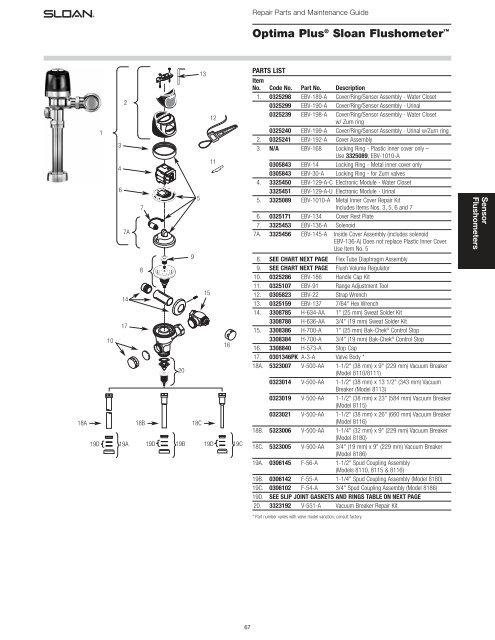
Repair Parts and <strong>Maintenance</strong> <strong>Guide</strong><br />
<strong>Optima</strong> <strong>Plus</strong> ® <strong>Sloan</strong> <strong>Flushometer</strong> <br />
18A<br />
1<br />
10<br />
3<br />
4<br />
6<br />
2<br />
7A<br />
14<br />
17<br />
7<br />
8<br />
18B<br />
18C<br />
19D 19A 19D 19B 19D 19C<br />
20<br />
9<br />
5<br />
13<br />
15<br />
12<br />
11<br />
16<br />
PARTS LIST<br />
Item<br />
No. Code No. Part No. Description<br />
1. 0325298 EBV-189-A Cover/Ring/Sensor Assembly - Water Closet<br />
0325299 EBV-190-A Cover/Ring/Sensor Assembly - Urinal<br />
0325239 EBV-198-A Cover/Ring/Sensor Assembly - Water Closet<br />
w/ Zurn ring<br />
0325240 EBV-199-A Cover/Ring/Sensor Assembly - Urinal w/Zurn ring<br />
2. 0325241 EBV-192-A Cover Assembly<br />
3. N/A EBV-168 Locking Ring - Plastic inner cover only –<br />
Use 3325089, EBV-1010-A<br />
0305843 EBV-14 Locking Ring - Metal inner cover only<br />
0305843 EBV-30-A Locking Ring - for Zurn valves<br />
4. 3325450 EBV-129-A-C Electronic Module - Water Closet<br />
3325451 EBV-129-A-U Electronic Module - Urinal<br />
5. 3325089 EBV-1010-A Metal Inner Cover Repair Kit<br />
Includes Items Nos. 3, 5, 6 and 7<br />
6. 0325171 EBV-134 Cover Rest Plate<br />
7. 3325453 EBV-136-A Solenoid<br />
7A. 3325456 EBV-145-A Inside Cover Assembly (includes solenoid<br />
EBV-136-A) Does not replace Plastic Inner Cover.<br />
Use Item No. 5<br />
8. SEE CHART NEXT PAGE Flex Tube Diaphragm Assembly<br />
9. SEE CHART NEXT PAGE Flush Volume Regulator<br />
10. 0325286 EBV-186 Handle Cap Kit<br />
11. 0325107 EBV-91 Range Adjustment Tool<br />
12. 0305823 EBV-22 Strap Wrench<br />
13. 0325159 EBV-137 7/64" Hex Wrench<br />
14. 3308785 H-634-AA 1" (25 mm) Sweat Solder Kit<br />
3308788 H-636-AA 3/4" (19 mm) Sweat Solder Kit<br />
15. 3308386 H-700-A 1" (25 mm) Bak-Chek ® Control Stop<br />
3308384 H-700-A 3/4" (19 mm) Bak-Chek ® Control Stop<br />
16. 3308840 H-573-A Stop Cap<br />
17. 0301346PK A-3-A <strong>Valve</strong> Body *<br />
18A. 5323007 V-500-AA 1-1/2" (38 mm) x 9" (229 mm) Vacuum Breaker<br />
(Model 8110/8111)<br />
0323014 V-500-AA 1-1/2" (38 mm) x 13 1/2" (343 mm) Vacuum<br />
Breaker (Model 8113)<br />
0323019 V-500-AA 1-1/2" (38 mm) x 23" (584 mm) Vacuum Breaker<br />
(Model 8115)<br />
0323021 V-500-AA 1-1/2" (38 mm) x 26" (660 mm) Vacuum Breaker<br />
(Model 8116)<br />
18B. 5323006 V-500-AA 1-1/4" (32 mm) x 9" (229 mm) Vacuum Breaker<br />
(Model 8180)<br />
18C. 5323005 V-500-AA 3/4" (19 mm) x 9" (229 mm) Vacuum Breaker<br />
(Model 8186)<br />
19A. 0306145 F-56-A 1-1/2" Spud Coupling Assembly<br />
(Models 8110, 8115 & 8116)<br />
19B. 0306142 F-55-A 1-1/4" Spud Coupling Assembly (Model 8180)<br />
19C. 0306102 F-54-A 3/4" Spud Coupling Assembly (Model 8186)<br />
19D. SEE SLIP JOINT GASKETS AND RINGS TABLE ON NEXT PAGE<br />
20. 3323192 V-551-A Vacuum Breaker Repair Kit<br />
Sensor<br />
<strong>Flushometer</strong>s<br />
* Part number varies with valve model variation; consult factory.<br />
67
Repair Parts and <strong>Maintenance</strong> <strong>Guide</strong><br />
<strong>Optima</strong> <strong>Plus</strong> ® <strong>Sloan</strong> <strong>Flushometer</strong> <br />
LOCKING RING<br />
COVER<br />
BODY<br />
FLUSH CONNECTION<br />
(VACUUM BREAKER)<br />
OVERRIDE BUTTON<br />
STOP COUPLING<br />
TAILPIECE<br />
OUTLET COUPLING<br />
CONTROL STOP<br />
SUPPLY FLANGE<br />
ITEM 8. FLEX TUBE DIAPHRAGM KIT<br />
Regulator<br />
Code No. Part No. Description Color *<br />
3325150 EBV-1050-A Urinal-0.5 gpf/1.9 Lpf GREEN<br />
3325151 EBV-1051-A Urinal-1.0 gpf/3.8 Lpf † GREEN<br />
3325153 EBV-1053-A Closet-1.6 gpf/6.0 Lpf † GREEN<br />
3325152 EBV-1052-A Closet-2.4 gpf/9.0 Lpf BLUE<br />
† The EBV-1051-A and EBV-1053-A Kits are supplied with multiple Regulators.<br />
* Color of regulator to be used with flex tube diaphragm to obtain the listed flush volume.<br />
A 1.0 gpf (3.8 Lpf) Urinal kit can be converted to a 1.5 gpf (5.7 Lpf) Urinal by replacing<br />
the Green Regulator with the supplied Black Regulator.<br />
A 1.6 gpf (6.0 Lpf) Closet kit can be converted to a 3.5 gpf (13.2 Lpf) Closet by replacing<br />
the Green Regulator with the supplied White Regulator.<br />
Sensor<br />
<strong>Flushometer</strong>s<br />
SPUD COUPLING<br />
SPUD FLANGE<br />
OPERATION<br />
A continuous, INVISIBLE light beam is emitted from the <strong>Optima</strong> <strong>Plus</strong> ® Sensor.<br />
As the user enters the beam's effective range, 22 to 42 inches (559 mm to<br />
1067 mm) for closet installations and 15 to 30 inches (381 mm to 762 mm)<br />
for urinal installations, the beam is reflected into the Scanner Window to<br />
activate the Output Circuit. Once activated, the Output Circuit continues in a<br />
“hold” mode for as long as the user remains within the effective range of<br />
the sensor.<br />
When the user steps away, the loss of reflected light initiates an electrical<br />
“one-time” signal that activates the flushing cycle to flush the fixture. The<br />
Circuit automatically resets and is ready for the next user.<br />
ITEM 9. REGULATORS<br />
The flush volume of the flex tube diaphragm kit is controlled by the<br />
regulator. Regulators are identified by color. Some flex tube diaphragm kits<br />
are supplied with multiple regulators. The installer must make sure the<br />
proper regulator is used when installing the flex tube diaphragm kit.<br />
REGULATOR (SOLD 6 PER PACKAGE)<br />
Regulator<br />
Code No. Part No. Description Color<br />
5325122 EBV-95 Urinal-0.5 gpf/1.9 Lpf GREEN<br />
5325122 EBV-95 Urinal-1.0 gpf/3.8 Lpf GREEN<br />
5325122 EBV-95 Closet-1.6 gpf/6.0 Lpf GREEN<br />
5325128 EBV-101 Closet-2.4 gpf/9.0 Lpf BLUE<br />
FLEX TUBE DIAPHRAGM ASSEMBLY<br />
0-RING<br />
REGULATOR<br />
(MUST BE<br />
INSTALLED<br />
PAST 0-RING)<br />
<strong>Optima</strong> <strong>Plus</strong> <strong>Valve</strong> Models Feature <strong>Sloan</strong>’s<br />
Exclusive Flex Tube Diaphragm for the<br />
ultimate in valve performance, reliability and<br />
Chloramine resistance.<br />
FLEX TUBE<br />
DIAPHRAGM<br />
ITEM 19D. SLIP JOINT GASKETS AND RINGS<br />
Size Code No. Part No. Description<br />
1-1/2” 5306058 F-3 Red Friction Ring<br />
5322001 VBF-5 Black Slip Joint Gasket<br />
0319086/5319086 S-30 Flexible Seat<br />
0319079 S-21 Rigid Seat (rubber over brass)<br />
1-1/2” x 1-1/4” 0396062 F-105 Slip Joint Gasket – Rigid<br />
1-1/4” 5306057 F-3 Red Friction Ring<br />
5322176 VBF-5 Black Slip Joint Gasket<br />
0307052/5307052 G-21 Rigid Seat (rubber over brass)<br />
1” 5306056 F-3 Red Friction Ring<br />
5306115 F-5 Black Slip Joint Gasket<br />
3/4” 5306055 F-3 Red Friction Ring<br />
5306113 F-5 Black Slip Joint Gasket<br />
68
Repair Parts and <strong>Maintenance</strong> <strong>Guide</strong><br />
<strong>Optima</strong> <strong>Plus</strong> ® <strong>Sloan</strong> <strong>Flushometer</strong> <br />
BATTERY REPLACEMENT<br />
When required, replace batteries with four (4) Alkaline AA-Size Batteries.<br />
Note: Water does not have to be turned off to replace batteries.<br />
Loosen the two (2) Screws on top of unit. Remove the complete Cover<br />
Assembly. Lift the Sensor Module from its Plate. Unplug the Electrical<br />
Connector from Battery Compartment Cover. Loosen the Retaining Screw on<br />
Battery Compartment Cover and remove Battery Compartment Cover. Install<br />
four (4) Alkaline AA-Size Batteries exactly as illustrated.<br />
Install Battery Compartment Cover and secure with Retaining Screw. Make<br />
certain that Battery Compartment Cover is fully compressed against Gasket<br />
to provide a seal; Do Not overtighten. Plug the Electrical Connector into the<br />
Battery Compartment Cover. Reinstall the Sensor Module onto the Plate.<br />
Reinstall the complete Cover Assembly onto the Plate. Tighten the two (2)<br />
Screws on top of the unit.<br />
7/64” ALLEN WRENCH<br />
COVER ASSEMBLY<br />
SENSOR MODULE<br />
PLATE<br />
SENSOR MODULE (BACKSIDE SHOWN)<br />
RETAINING SCREW<br />
ELECTRICAL CONNECTOR<br />
RECEPTACLE<br />
Sensor<br />
<strong>Flushometer</strong>s<br />
BATTERY COMPARTMENT COVER<br />
RANGE ADJUSTMENT (ADJUST ONLY IF NECESSARY)<br />
The <strong>Optima</strong> <strong>Plus</strong> ® has a factory set sensing range:<br />
Water Closet Models - 22" to 42" (559 mm to 1067 mm)<br />
Urinal Models - 15" to 30" (381 mm to 762 mm)<br />
The Factory setting should be satisfactory for most installations.<br />
If the range is too short (i.e., not picking up users) or too long (i.e., picking<br />
up opposite wall or stall door) the range can be adjusted.<br />
Note: Water does not have to be turned off to adjust range.<br />
Refer to Illustration on at right.<br />
Loosen the two Screws on top of the unit. Remove the Override Button.<br />
Remove the Rubber Plug from top of Electronic Sensor Module to uncover<br />
the Potentiometer.<br />
COUNTER-<br />
CLOCKWISE<br />
Decreases<br />
Range<br />
CLOCKWISE<br />
Increases<br />
Range<br />
RANGE ADJUSTMENT PROCEDURE<br />
For the first ten (10) minutes of operation, a Visible Red Light flashes in the<br />
Sensing Window of the <strong>Optima</strong> <strong>Plus</strong> <strong>Flushometer</strong> when a user is detected.<br />
This Visible Red Light feature can be reactivated after ten (10) minutes by<br />
opening and closing the Battery Compartment Door.<br />
Check the range by stepping toward the unit until the Red Light flashes,<br />
indicating the Sensor's maximum detection limit. Adjust the Range<br />
Potentiometer Screw located on top of the Sensor Module a few degrees<br />
CLOCKWISE to increase the range or a few degrees COUNTERCLOCKWISE<br />
to decrease the range. Repeat this adjustment until the desired range is<br />
achieved.<br />
Always Determine the Sensing Range with Plastic Cover and Lens<br />
Window On Top of the Unit.<br />
Important: Adjust in small increments only! Range Potentiometer<br />
Adjustment Screw rotates only 3/4 of a turn; DO NOT over-rotate.<br />
When range adjustment is satisfactory, replace the Rubber Plug. Reinstall<br />
Override Button and tighten the two Screws on top of the unit.<br />
69
Repair Parts and <strong>Maintenance</strong> <strong>Guide</strong><br />
<strong>Optima</strong> <strong>Plus</strong> ® <strong>Sloan</strong> <strong>Flushometer</strong> <br />
Sensor<br />
<strong>Flushometer</strong>s<br />
TROUBLESHOOTING AND MAINTAINING THE SLOAN OPTIMA PLUS ® FLUSHOMETER<br />
IMPORTANT: This product contains mechanical and/or electrical<br />
components that are subject to normal wear. These components should<br />
be checked on a regular basis and replaced as needed to maintain the<br />
valve’s performance.<br />
Never open Control Stop to where the flow from the valve exceeds the flow<br />
capability of the fixture. In the event of a valve failure, the fixture must be<br />
able to accommodate a continuous flow from the valve.<br />
ATTENTION INSTALLERS: With the exception of the control stop inlet,<br />
DO NOT USE pipe sealant or plumbing grease on any valve component or<br />
coupling! To protect the chrome or special finish of <strong>Sloan</strong> flushometers,<br />
DO NOT USE toothed tools to install or service these valves. Use our A-50<br />
Super-Wrench or other smooth-jawed wrench to secure couplings.<br />
Regulations for low consumption fixtures (1.6 gpf/6.0 Lpf closets and<br />
1.0 gpf/3.8 Lpf urinals) prohibit use of higher flush volumes.<br />
1. Sensor flashes continuously only when user steps<br />
within range.<br />
A. Unit in Start-Up mode; no problem. This feature is active for the first<br />
ten (10) minutes of operation.<br />
2. <strong>Valve</strong> does not flush; sensor not picking up user.<br />
A. Range too short; increase the range.<br />
3. <strong>Valve</strong> does not flush; sensor picking up opposite wall or surface,<br />
or only flushes when someone walks by. Red light flashes<br />
continuously for first 10 minutes even with no one in front of<br />
the sensor.<br />
A. Range too long; shorten range.<br />
4. <strong>Valve</strong> does not flush even after adjustment.<br />
A. Range Adjustment Potentiometer set at full “max” or full “min” setting.<br />
Readjust Potentiometer away from full “max” or “min” setting.<br />
B. Batteries completely used up; replace batteries.<br />
C. Problem with Electronic Sensor Module; replace Electronic Sensor<br />
Module.<br />
5. Unit flashes four (4) quick times when user steps within range.<br />
A. Batteries low; replace batteries.<br />
6. <strong>Valve</strong> does not shut off.<br />
A. Bypass Orifice in Diaphragm is clogged with dirt or debris, or Bypass<br />
is clogged by an invisible gelatinous film due to “over-treated” water.<br />
Remove Flex Tube Diaphragm and wash under running water.<br />
Note: Size of orifice in the by-pass is of utmost importance for the<br />
proper metering of water by the valve. DO NOT ENLARGE OR<br />
DAMAGE THIS ORIFICE. Replace flex tube diaphragm if cleaning<br />
does not correct the problem.<br />
B. Dirt or debris fouling Stem or Flex Tube Diaphragm. Remove Flex Tube<br />
Diaphragm and wash under running water.<br />
C. O-ring on Stem of Flex Tube Diaphragm is damaged or worn. Replace<br />
O-ring if necessary.<br />
D. Problem with Electronic Sensor Module; replace Sensor Module.<br />
7. Not enough water to fixture.<br />
A. Wrong Flush Volume Regulator installed in Flex Tube Diaphragm Kit.<br />
Install the correct Regulator (see Step 6 of these instructions).<br />
B. Wrong <strong>Optima</strong> <strong>Plus</strong> ® Diaphragm kit installed; i.e., 1 gpf. urinal<br />
installed on 3.5 gal. closet fixture. Replace with proper <strong>Optima</strong> <strong>Plus</strong><br />
diaphragm kit.<br />
C. Enlarged Bypass in Diaphragm. Replace Flex Tube Diaphragm.<br />
D. Control Stop not adjusted properly. Readjust Control Stop.<br />
E. Inadequate volume or pressure at supply. Increase water pressure or<br />
supply (flow) to valve. Consult factory for assistance.<br />
8. Too much water to fixture.<br />
A. Wrong Flush Volume Regulator installed in Flex Tube Diaphragm Kit.<br />
Install the correct Regulator (see Step 6 of these instructions).<br />
B. Control Stop not adjusted properly. Readjust Control Stop.<br />
C. Wrong <strong>Optima</strong> <strong>Plus</strong> Diaphragm kit installed; i.e., 3.5 gpf. closet<br />
installed on 0.5 gal. urinal fixture. Replace with proper <strong>Optima</strong> <strong>Plus</strong><br />
Diaphragm kit.D. Dirt in Diaphragm Bypass. Clean under running<br />
water or replace Flex Tube Diaphragm.<br />
CARE AND CLEANING OF CHROME AND SPECIAL FINISHES<br />
DO NOT use abrasive or chemical cleaners to clean flushometers as they<br />
may dull the luster and attack the chrome or special decorative finishes.<br />
Use ONLY soap and water, then wipe dry with clean cloth or towel.<br />
While cleaning the bathroom tile, the flushometer should be protected from<br />
any splattering of cleaner. Acids and cleaning fluids can discolor or remove<br />
chrome plating.<br />
When assistance is required, please contact<br />
<strong>Sloan</strong> <strong>Valve</strong> <strong>Company</strong> Installation Engineering<br />
Department at: 1-888-SLOAN-14 (1-888-756-2614).<br />
70


