

Installation Instructions - Sloan Valve Company
Installation Instructions - Sloan Valve Company
Installation Instructions - Sloan Valve Company

You also want an ePaper? Increase the reach of your titles
YUMPU automatically turns print PDFs into web optimized ePapers that Google loves.
Code No. 0816323<br />
Rev. 2 (08/10)<br />
INSTALLATION INSTRUCTIONS FOR BATTERY POWERED<br />
SENSOR ACTIVATED HAND WASHING FAUCETS<br />
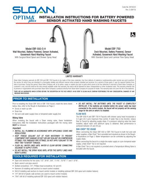
Model EBF-550-S-H<br />
Wall Mounted, Battery Powered, Sensor Activated,<br />
Gooseneck Hand Washing Faucet<br />
With Surgical Bend Spout and Shower Spray Head<br />
Model EBF-750<br />
Deck Mounted, Battery Powered, Sensor<br />
Activated, Gooseneck Hand Washing Faucet<br />
With Standard Spout and Laminar Flow Spray Head<br />
LIMITED WARRANTY<br />
<strong>Sloan</strong> <strong>Valve</strong> <strong>Company</strong> warrants its EBF-550 and EBF-750 Faucets to be made of first class materials, free from defects of material or workmanship under normal use and to perform<br />
the service for which they are intended in a thoroughly reliable and efficient manner when properly installed and serviced, for a period of three years (1 year for special finishes) from<br />
date of purchase. During this period, <strong>Sloan</strong> <strong>Valve</strong> <strong>Company</strong> will, at its option, repair or replace any part or parts which prove to be thus defective if returned to <strong>Sloan</strong> <strong>Valve</strong> <strong>Company</strong>, at<br />
customer's cost, and this shall be the sole remedy available under this warranty. No claims will be allowed for labor, transportation or other incidental costs. This warranty extends only<br />
to persons or organizations who purchase <strong>Sloan</strong> <strong>Valve</strong> <strong>Company</strong>'s products directly from <strong>Sloan</strong> <strong>Valve</strong> <strong>Company</strong> for purpose of resale. This warranty does not cover the life of the batteries.<br />
THERE ARE NO WARRANTIES WHICH EXTEND BEYOND THE DESCRIPTION ON THE FACE HEREOF. IN NO EVENT IS SLOAN VALVE COMPANY RESPONSIBLE FOR ANY CONSEQUENTIAL DAMAGES OF ANY<br />
MEASURE WHATSOEVER.<br />
PRIOR TO INSTALLATION<br />
Prior to installing the <strong>Sloan</strong> EBF-550 or EBF-750 Faucet, install the items listed<br />
below. Also, refer to the Rough-In illustrations on Page 2.<br />
• Scrub or wash-up sink<br />
• Drain line<br />
• Hot and cold water supply lines or tempered water supply line<br />
Mixing <strong>Valve</strong><br />
When installing the faucet with a <strong>Sloan</strong> mixing valve, these <strong>Installation</strong><br />
<strong>Instructions</strong> AND the <strong>Installation</strong> <strong>Instructions</strong> packaged with the mixing valve<br />
MUST be followed.<br />
Important:<br />
• INSTALL ALL PLUMBING IN ACCORDANCE WITH APPLICABLE CODES AND<br />
REGULATIONS.<br />
• KEEP THREAD SEALANT OUT OF YOUR WATERWAY TO PREVENT<br />
COMPONENT PART DAMAGE! DO NOT USE ANY SEALANT ON COMPRESSION<br />
FITTINGS. FOR THREADED PIPE FITTINGS, DO NOT APPLY SEALANT TO THE<br />
FIRST TWO “STARTER” THREADS.<br />
• FLUSH ALL WATER LINES UNTIL WATER IS CLEAR BEFORE CONNECTING<br />
SOLENOID TO SUPPLY STOPS.<br />
• DO NOT INSTALL THE SPRAY HEAD UNTIL AFTER THE SUPPLY LINES HAVE<br />
BEEN FLUSHED.<br />
TOOLS REQUIRED FOR INSTALLATION<br />
• DO NOT INSTALL THE BATTERIES UNTIL THE FAUCET IS COMPLETELY<br />
INSTALLED. If the batteries are installed before the sensor cable has been<br />
connected to the control module, the faucet will not properly set the sensing<br />
range for the sink on which it is installed.<br />
FLOW RATE<br />
The EBF-550-H and EBF-750-H Faucets with shower spray head incorporate a<br />
2.2 gpm (8.3 Lpm) maximum flow control. If water flow is too forceful, reduce<br />
flow to Faucet by adjusting supply stops. If a pressure reducing valve has been<br />
installed, adjust valve until optimum spray is obtained. Best performance is<br />
achieved between 25 and 40 psi.<br />
BAK-CHEK ® TEE USAGE<br />
When connecting the <strong>Sloan</strong> EBF-550 or EBF-750 Faucet to both hot and cold<br />
water supplies, a Bak-Chek ® Tee is provided and required as shown in the Roughin<br />
illustrations on Page 2. Water temperature can be controlled by adjusting the<br />
supply stops.<br />
When connecting the faucet to a single line water supply or a pre-tempered water<br />
supply, a Bak-Chek ® Tee is not required.<br />
A Bak-Chek ® Tee is not required or provided when a Temperature Mixing <strong>Valve</strong> is<br />
included with the faucet.<br />
• Open end wrenches for hex sizes: 1/2”, 9/16”, 5/8”, 11/16”, 15/16” 1” and 1-3/16”.<br />
• Basin wrench and pipe wrench<br />
• Slotted screwdriver, 1/4”; Phillips head screwdriver, #2 and #3<br />
• Hammer (if installing wall anchors to mount control module)<br />
• Drill (if installing wall anchors to mount control module or installing optional EBF-550 spout anti-rotation feature)<br />
• 1/4” drill bit (if plastic wall anchors are used to mount control module)<br />
• 7/64” drill bit (if installing optional EBF-550 spout anti-rotation feature)
FAUCET ROUGH-IN<br />
EBF-550 Faucet with Bak-Chek ® Tee or BDM and BDT<br />
Variation Mixing <strong>Valve</strong>s for Hot and Cold Water Supply or Single<br />
Line Water Supply †<br />
EBF-550-H with Standard Spout and Shower<br />
Spray Head †<br />
EBF-750-H with Standard Spout and Shower<br />
Spray Head †<br />
ADAPTER<br />
(OPTIONAL)<br />
EBF-550-S-H with Surgical Bend Spout and<br />
Shower Spray Head †<br />
EBF-750-S-H with Surgical Bend Spout<br />
and Shower Spray Head †<br />
ADAPTER<br />
DAPTER<br />
(OPTIONAL)<br />
APTER PTIONAL)<br />
TIONAL)<br />
ADAPTER<br />
(OPTIONAL)<br />
ADAPTER<br />
ADAPTER (OPTIONAL)<br />
(OPTIONAL) ADAPTER<br />
(OPTIONAL)<br />
ADAPTER<br />
(OPTIONAL)<br />
† The wide Spray Head is recommended for use on scrub or deep wash-up sinks only. For<br />
lavatories and small basins, use the Laminar Flow Spray Head.<br />
ADAPTER<br />
EBF-750 (OPTIONAL) Faucet with Bak-Chek ® Tee for Hot and Cold<br />
Water Supply †<br />
EBF-750 Faucet with ADM Variation Mixing <strong>Valve</strong> for Hot<br />
and Cold Water Supply † (shown with 8” trim plate)<br />
EBF-750 Faucet with BDM and BDT Variation Mixing<br />
<strong>Valve</strong>s for Hot and Cold Water Supply †<br />
ADAPTER<br />
(OPTIONAL)<br />
ADAPTER<br />
(OPTIONAL)<br />
ADAPTER<br />
(OPTIONAL)<br />
ADAPTER<br />
(OPTIONAL)<br />
A<br />
(OP<br />
ADAPTER<br />
(OPTIONAL)<br />
ADAPTER<br />
(OPTIONAL)<br />
ADAPTER<br />
(OPTIONAL)<br />
2
1A - INSTALL FAUCET SPOUT – EBF-750<br />
Note: When installing with a <strong>Sloan</strong> Mixing <strong>Valve</strong>, install Faucet and Trim Plate<br />
before installing Mixing <strong>Valve</strong>. For complete installation guidelines, refer to the<br />
<strong>Installation</strong> <strong>Instructions</strong> supplied with the <strong>Sloan</strong> mixing valve.<br />
SPOUT<br />
A<br />
Insert Sensor Cable and Spout Shank through Base Gasket, optional<br />
Trim Plate with Spacer, and center deck hole.<br />
SPOUT SHANK<br />
TRIM PLATE<br />
(OPTIONAL)<br />
B<br />
Secure using the Flat Washer, Lockwasher and Nut supplied.<br />
BASE GASKET<br />
SPACER (MUST BE<br />
USED WITH TRIM<br />
PLATE)<br />
FLAT WASHER<br />
SINK IS SHOWN CUT<br />
AWAY<br />
LOCKWASHER<br />
1B - INSTALL FAUCET SPOUT – EBF-550<br />
OPTIONAL ANTI-ROTATION FEATURE<br />
Note: The anti-rotation feature uses a screw to anchor the faucet in the<br />
vertical position and is intended for use ONLY on stainless steel sinks.<br />
C<br />
FAUCET SENSOR CABLE<br />
NUT<br />
Drill a 7/64" (3 mm) diameter hole through the stainless steel<br />
mounting surface at the location just marked.<br />
A<br />
B<br />
Place the Base Gasket over the faucet mounting hole using it as a<br />
template.<br />
Mark the stainless steel mounting surface at the center of the small<br />
hole at the bottom of the Base Gasket.<br />
FAUCET MOUNTING HOLE OF<br />
STAINLESS STEEL SURFACE<br />
DRILL 7/64” (3 mm) HOLE<br />
AT MARK PLACED ON<br />
STAINLESS STEEL<br />
MOUNTING SURFACE<br />
STAINLESS STEEL<br />
MOUNTING SURFACE<br />
D<br />
After Faucet body is mounted, insert the Self-Tapping Screw through<br />
the drilled hole and into the small hole in the back of the Faucet body.<br />
Tighten the Screw.<br />
Note: When installing the faucet with a <strong>Sloan</strong> mixing valve, both these<br />
<strong>Installation</strong> <strong>Instructions</strong> AND those packaged with the mixing valve MUST<br />
be followed.<br />
BASE<br />
GASKET<br />
SELF-TAPPING<br />
SCREW<br />
BASE<br />
GASKET<br />
TO MOUNT ON SURFACE LESS THAN 0.41" (10 mm) THICK<br />
NUT<br />
A<br />
Route Sensor Cable through groove on side of Spout Shank.<br />
LOCKWASHER<br />
B<br />
C<br />
Insert Sensor Cable and Spout Shank through the Base Gasket and<br />
mounting hole of wall or sink.<br />
Secure Faucet with the Flat Washer, Lockwasher and Nut Supplied.<br />
FLAT WASHER<br />
MOUNTING HOLE OF<br />
WALL OR SINK<br />
SENSOR CABLE<br />
SPOUT<br />
SHANK<br />
BASE GASKET<br />
TO MOUNT ON SURFACE BETWEEN 0.41" (10 mm) AND 1" (25 mm) THICK<br />
A<br />
B<br />
C<br />
D<br />
Screw Mounting Stud into end of Spout Shank.<br />
Route Sensor Cable through groove on side of Spout Shank.<br />
Insert Sensor Cable and Spout Shank through the Base Gasket and<br />
mounting hole of wall or sink.<br />
From behind wall, install Mounting Spacer onto Faucet Shank as<br />
illustrated. The Mounting Stud should protrude through the smaller<br />
hole of the Mounting Spacer.<br />
Note: <strong>Sloan</strong> <strong>Valve</strong> <strong>Company</strong> does NOT supply hardware necessary for mounting<br />
the Faucet on surfaces thicker than 1" (25 mm).<br />
F<br />
Install Male Connector into Spout Shank.<br />
MOUNTING SPACER<br />
HEX JAM NUT DO<br />
NOT OVERTIGHTEN<br />
LOCKWASHER<br />
FLAT WASHER<br />
MOUNTING<br />
HOLE OF<br />
WALL OR<br />
SINK<br />
MOUNTING<br />
STUD<br />
SPOUT<br />
SHANK<br />
E<br />
Secure using the Flat Washer, Lockwasher and Hex Jam Nut supplied.<br />
Do NOT overtighten the Hex Jam Nut.<br />
3<br />
BASE<br />
GASKET<br />
MALE<br />
CONNECTOR
2 - Install Solenoid <strong>Valve</strong> (Models EBF-550 and EBF-750)<br />
A<br />
Thread Male Connector<br />
into inlet hole at bottom<br />
of Spout Shank if not<br />
already installed. Tighten<br />
Male Connector securely<br />
to prevent leaks.<br />
Model<br />
EBF-550<br />
SPOUT SHANK<br />
MALE CONNECTOR<br />
3/8" (10 mm) SUPPLY TUBE<br />
(FURNISHED BY INSTALLER)<br />
Flow direction of Solenoid<br />
<strong>Valve</strong> is indicated by an<br />
arrow on <strong>Valve</strong> Body.<br />
A<br />
B<br />
Install the 3/8” (10 mm) Straight Compression<br />
Fitting onto the Spout’s copper Supply Tube.<br />
Connect 3/8" (10 mm) supply tube (furnished<br />
by installer) between the Compression Fittings<br />
on Spout and top outlet of<br />
Solenoid <strong>Valve</strong>.<br />
Model<br />
EBF-750<br />
B<br />
Connect 3/8" (10 mm)<br />
supply tube (furnished<br />
by installer) between the<br />
Compression Fittings on<br />
Spout and top outlet of<br />
Solenoid <strong>Valve</strong>.<br />
3/8” (10 mm) SOLENOID<br />
VALVE COMPRESSION<br />
CONNECTION (TOP<br />
OUTLET)<br />
SENSOR<br />
CABLE<br />
SPOUT<br />
3/8” (10 mm) SUPPLY TUBE<br />
SOLENOID VALVE<br />
3/8” (10 mm) SOLENOID<br />
VALVE COMPRESSION<br />
CONNECTION (BOTTOM<br />
INLET)<br />
3/8” (10 mm) STRAIGHT<br />
COMPRESSION FITTING<br />
3/8" (10 mm) SUPPLY TUBE<br />
(FURNISHED BY INSTALLER)<br />
3/8” (10 mm) SOLENOID<br />
VALVE COMPRESSION<br />
CONNECTION (TOP OUTLET)<br />
SOLENOID VALVE<br />
3/8” (10 mm) SOLENOID VALVE<br />
COMPRESSION CONNECTION<br />
(BOTTOM INLET)<br />
3 - Connect Supply Line(s) from Supply Stop(s) to Solenoid <strong>Valve</strong> Inlet<br />
Important: Keep thread sealant out of your waterway and prevent component<br />
part damage! Do not use sealant on compression fittings. When thread<br />
sealant is used, do not apply it to the first two “starter” threads.<br />
Important: Flush dirt, debris, and sediment from the supply line(s).<br />
A<br />
Dual Line Hot and Cold Water Supply Applications<br />
Install a 3/8 inch (10 mm) copper supply tube<br />
between Bak-Chek ® Compression Tee and hot and<br />
cold supply stops. (Supply tubes and stops<br />
furnished by installer.) Install a 3/8 inch (10 mm)<br />
copper supply tube between Bak-Chek<br />
Compression Tee and inlet side of Solenoid <strong>Valve</strong>.<br />
Tighten Compression Fittings securely.<br />
Note: Failure to install the Bak-Chek ® Tee can result in a<br />
cross flow connection when the faucet is off and the<br />
supply stops are open. If pressure of the hot and<br />
cold water supply differ, hot water can migrate<br />
into the cold water supply or vice-versa.<br />
Most plumbing codes require that the<br />
Bak-Chek ® be used to prevent this.<br />
3/8” (10 mm)<br />
BAK-CHEK TEE USED<br />
ON DUAL WATER<br />
SUPPLY<br />
APPLICATIONS ONLY<br />
SOLENOID<br />
VALVE<br />
3/8” (10 mm)<br />
SUPPLY TUBE<br />
3/8” (10 mm)<br />
COMPRESSION<br />
FITTING<br />
SUPPLY<br />
STOP<br />
B<br />
SOLENOID<br />
VALVE<br />
3/8” (10 mm)<br />
SUPPLY TUBE<br />
3/8” (10 mm)<br />
COMPRESSION<br />
FITTING<br />
SUPPLY<br />
STOP<br />
SENSOR<br />
CABLE<br />
Single Line Water Supply Applications<br />
Install a 3/8 inch (10 mm) copper supply tube between the supply stop<br />
and inlet side of Solenoid <strong>Valve</strong>. (Supply tube and supply stop furnished<br />
by installer.) Tighten Compression Fittings securely.<br />
4 - Mount Control Module to Wall<br />
A<br />
B<br />
Install the Control Module in an appropriate location. Control Module<br />
must be installed so that all cables enter from the bottom of the unit.<br />
When installed, Cables from the Spout and Solenoid <strong>Valve</strong> to the<br />
Control Module should have some slack.<br />
Mount Control Module to wall using Mounting Screws and Plastic<br />
Anchors.<br />
4” (102 mm)<br />
4
5 - Control Module Connection<br />
A Route Cables from Solenoid <strong>Valve</strong> and Spout to the Control Module. CONTROL<br />
MODULE<br />
ENCLOSURE<br />
Insert Locking Connector from Solenoid <strong>Valve</strong> into mating Receptacle.<br />
B<br />
C<br />
D<br />
Insert Connector from Faucet Spout into Modular Receptacle.<br />
Insert Power Cable Jack from Transformer (optional) into Receptacle.<br />
POWER CABLE<br />
JACK<br />
MODULAR<br />
RECEPTACLE<br />
E<br />
Insert each Cable into a Strain Relief Slot.<br />
LOCKING<br />
CONNECTOR<br />
STRAIN<br />
RELIEF<br />
SLOTS<br />
FROM TRANSFORMER<br />
FROM SOLENOID VALVE<br />
FROM FAUCET SPOUT<br />
6 - Install Batteries and Plug in Adapter (Optional)<br />
A<br />
Insert four (4) AA-size Alkaline Batteries provided as indicated by the<br />
(+) and (—) symbols inside the Battery Compartment.<br />
B<br />
Plug Adapter (optional) into Receptacle.<br />
CONTROL MODULE<br />
BATTERY<br />
COMPARTMENT<br />
ADAPTER<br />
(OPTIONAL)<br />
7 - Start-Up<br />
A<br />
FOUR (4) AA-SIZE ALKALINE<br />
BATTERIES<br />
Activate ( "dry fire") Faucet by placing hands in front of the Sensor. The<br />
Solenoid <strong>Valve</strong> should “click.” Once hands are removed the Solenoid<br />
<strong>Valve</strong> should click again. If this does not occur, refer to the<br />
Troubleshooting section of this instruction manual.<br />
Once "dry firing" segment is complete, remove Aerator or Shower<br />
Spray Head. Open supply stop(s) then activate Faucet by placing hands<br />
in front of the Sensor. The Solenoid <strong>Valve</strong> should "click" and water<br />
should flow from the Spout.<br />
B<br />
C<br />
Activate Faucet for 30 seconds by placing hands in front of the Sensor.<br />
The Solenoid <strong>Valve</strong> should “click” and water should flow from the<br />
Spout. If this does not occur, refer to the Troubleshooting section of this<br />
installation instructions.<br />
Close supply stop(s) and reinstall Aerator or Spray Head in Spout.<br />
Reopen supply stop(s), activate Faucet and check for leaks.<br />
8 - Range Adjustment<br />
The OPTIMA Plus EBF-550 and EBF-750 Faucets are factory set to operate<br />
when hands are placed 4 to 5 inches (102 to 127 mm) from Sensor. This range<br />
should be satisfactory for most installations. If range adjustment is required,<br />
refer to the following range adjustment procedure.<br />
CONTROL<br />
MODULE<br />
A<br />
The Range Potentiometer is located in the Control Module.<br />
Important: Range Potentiometer adjustment screw rotates only 3/4 of a turn;<br />
DO NOT over-rotate. Over-rotating will damage range adjustment screw.<br />
B Cycle Faucet several times to assure that the Sensor will not<br />
inadvertently pick up reflection off the edge of the sink. If reflection<br />
occurs, adjust Range Potentiometer counterclockwise very slightly and<br />
again cycle Faucet.<br />
Repeat adjustment procedure until desired range is achieved.<br />
A SCREWDRIVER IS PROVIDED ON<br />
THE INSIDE COVER OF THE<br />
CONTROL MODULE FOR MAKING<br />
RANGE ADJUSTMENTS<br />
RANGE<br />
POTENTIOMETER<br />
5
9 - Noise Reduction (NR) and Time Out (Mode) Jumper Settings<br />
For jumper settings, refer to Table below or label on cover of Control Module<br />
along with the instructions in this Step.<br />
Noise Reduction (NR) Setting<br />
• When operating the faucet on batteries alone, set the NR jumper to<br />
bridge pins 1 and 2.<br />
• When operating the faucet using the plug-in transformer with<br />
battery backup, bridge pins 2 and 3.<br />
Time Out (Mode) Setting<br />
The Faucet Time Out Setting determines the maximum time the Faucet will<br />
run upon continuous activation. This timing can be changed to meet individual<br />
application requirements.<br />
Unless otherwise specified, Faucets leave the factory set with a 30 second<br />
Time Out.<br />
PINS<br />
DESCRIPTION<br />
1 2 3<br />
NOISE REDUCTION (NR) SETTING<br />
NR Enabled<br />
(Adapter w/Battery Backup Operation)<br />
Normal Operation<br />
(Battery Operation Only)<br />
TIME OUT (MODE) SETTING<br />
13.75 Second On Demand<br />
30 Second On Demand<br />
TIME OUT (MODE) JUMPER<br />
NOISE REDUCTION (NR) JUMPER<br />
10 - Install Cover onto Control Module<br />
A Install Cover over the Control Module making sure that all four (4)<br />
locking tabs snap into place. Secure using the two (2) screws provided.<br />
Cover can be installed in only one orientation.<br />
CONTROL MODULE<br />
CONTROL MODULE<br />
COVER<br />
COVER SCREW (2)<br />
LOCKING TAB (4)<br />
Operation<br />
1. A continuous invisible beam of infrared<br />
light is emitted from the OPTIMA ®<br />
Sensor.<br />
2. As the user’s hands enter the beam’s effective range,<br />
the beam is reflected back into the sensor receiver<br />
and activates the solenoid valve allowing water to flow<br />
from the faucet. Water will flow until the hands are<br />
removed<br />
or until<br />
the faucet<br />
reaches<br />
its<br />
automatic<br />
time out<br />
limit<br />
setting.<br />
3. When hands are moved away from the OPTIMA ®<br />
Sensor, the loss of reflected light initiates an<br />
electrical signal that deactivates the Solenoid <strong>Valve</strong>,<br />
shutting off the water flow. The Circuit then<br />
automatically<br />
resets and is<br />
ready for the<br />
next user.<br />
6
Care and Cleaning of Chrome and Special Finishes<br />
DO NOT USE abrasive or chemical cleaners (including chlorine bleach) to<br />
clean faucets that may dull the luster and attack the chrome or special<br />
decorative finishes. Use ONLY soap and water, then wipe dry with clean cloth<br />
or towel.<br />
While cleaning the bathroom tile, protect the faucet from any splattering of<br />
cleaner. Acids and cleaning fluids will discolor or remove chrome plating.<br />
Battery Replacement Procedure (Water Does NOT Need to be Turned Off)<br />
The <strong>Sloan</strong> Optima Plus EBF-550 and EBF-750 faucets are furnished with four<br />
(4) AA-size alkaline batteries that provide up to two (2) years of operation (8000<br />
cycles per month). A flashing LED signal indicates that battery power will be<br />
depleted within one (1) month.<br />
A<br />
Remove Cover as follows:<br />
1. Remove the two (2)<br />
Cover Screws.<br />
2. Press in the middle of<br />
both sides.<br />
3. Pull Cover straight out<br />
from Control Module<br />
Base.<br />
2<br />
1<br />
2<br />
B<br />
C<br />
Remove old batteries and<br />
insert four (4) new AA-size<br />
Alkaline Batteries as<br />
indicated by the (+) and<br />
(—) symbols inside the<br />
Battery Compartment.<br />
Reinstall Cover. Refer to<br />
Step 10.<br />
3<br />
Solenoid Screen Filter Cleaning Procedure<br />
A<br />
B<br />
Turn off water supply at supply stop(s). Activate Faucet to relieve<br />
system pressure.<br />
Remove Water Supply Line from Inlet Side of Solenoid <strong>Valve</strong>. Remove<br />
Cap, Water Line Fitting, Gasket, Filter Housing and Filter from Solenoid<br />
<strong>Valve</strong> Housing.<br />
D<br />
Reinstall Filter on Filter Housing.<br />
Install Filter Housing, Water Line Fitting, Gasket and Cap onto Solenoid<br />
<strong>Valve</strong> Housing.<br />
Tighten Cap securely.<br />
C<br />
Slide Filter off Filter Housing. Clean Filter using fresh tap water only. If<br />
necessary, use a small brush to clean. Use caution while cleaning to<br />
prevent damage to Filter.<br />
If any Filter components are damaged, replace as necessary. Examine<br />
the Gasket for wear or damage; replace if necessary.<br />
INLET SIDE OF SOLENOID VALVE HOUSING<br />
FILTER<br />
FILTER HOUSING<br />
WATER LINE FITTING<br />
GASKET<br />
CAP<br />
E<br />
Reinstall Water supply Line to Inlet Side of Solenoid <strong>Valve</strong>.<br />
7
Troubleshooting Guide<br />
1. PROBLEM: Sensor LED does not function (indicator light on sensor<br />
window in faucet spout does not flash during initial 10 minute<br />
set-up mode).<br />
CAUSE: There is no visible indicator light. Normal operation.<br />
SOLUTION: This is a normal operating feature of the faucet.<br />
2. PROBLEM: Faucet does not deliver any water when Sensor is activated.<br />
INDICATOR: Solenoid valve produces audible “CLICK.”<br />
CAUSE: Water supply stop(s) closed.<br />
SOLUTION: Open supply stop(s) completely.<br />
INDICATOR: Solenoid valve DOES NOT produce an audible “CLICK.”<br />
CAUSE: Solenoid Lead is not properly connected to the Control Module.<br />
SOLUTION: Disconnect and reconnect Solenoid Lead to Control Module.<br />
CAUSE: No battery or Transformer power is being supplied to Sensor.<br />
SOLUTION: Ensure that the batteries are installed properly. Check that the<br />
orientation of each battery matches the positive (+) and negative<br />
(—) symbols shown at bottom of battery compartment. Reinsert<br />
Batteries into Control Module. Transformer (optional) is<br />
unplugged or wall receptacle has no power.<br />
CAUSE: Sensor Cable is not properly connected to the Control Module.<br />
SOLUTION: Disconnect and reconnect Sensor Cable to Control Module.<br />
CAUSE: Sensor range is set at minimum distance.<br />
SOLUTION: Increase Sensor range. Refer to Step 8, Range Adjustment.<br />
CAUSE: Control Module assembly is defective.<br />
SOLUTION: Replace Control Module assembly.<br />
3. PROBLEM: Faucet delivers only a slow flow or dribble when Sensor is<br />
activated.<br />
CAUSE: Water supply stop(s) partially closed.<br />
SOLUTION: Open supply stop(s) completely.<br />
CAUSE: Solenoid Filter is clogged.<br />
SOLUTION: Remove, clean and reinstall Filter. Refer to Solenoid Screen Filter<br />
Cleaning Procedure on Page 7.<br />
CAUSE: Aerator or Spray Head is clogged.<br />
SOLUTION: Remove, clean and reinstall Aerator or Spray Head.<br />
4. PROBLEM: Faucet does not stop delivering water or continues to drip after<br />
user is no longer detected (automatic shut-off fails even when<br />
batteries are removed).<br />
CAUSE: Solenoid <strong>Valve</strong> has been connected backwards.<br />
SOLUTION: Disconnect Solenoid <strong>Valve</strong> compression fittings at both the inlet<br />
and outlet positions. The water should flow from inlet through<br />
the Solenoid <strong>Valve</strong> to the outlet according to the direction of the<br />
arrow shown on the side of the Solenoid <strong>Valve</strong>. Reconnect the<br />
compression fittings in the correct orientation.<br />
CAUSE: Solenoid <strong>Valve</strong> is dirty.<br />
SOLUTION: Backflush by reversing water flow (opposite to the direction<br />
shown by the arrow on the side of the Solenoid <strong>Valve</strong>) through<br />
the Solenoid <strong>Valve</strong>. Reconnect the compression fittings in the<br />
correct orientation. Activate faucet.<br />
CAUSE: Solenoid <strong>Valve</strong> Module is defective.<br />
SOLUTION: Replace Solenoid <strong>Valve</strong> Module.<br />
5. PROBLEM: The water temperature is too hot or too cold on a faucet<br />
connected to hot and cold supply lines with Bak-Chek ® Tee.<br />
CAUSE: Supply stops are not adjusted properly.<br />
SOLUTION: Adjust supply stops.<br />
NOTE: For some systems, a Thermostatic Mixing <strong>Valve</strong> may be required.<br />
6. PROBLEM: Red LED turns on in the control module (below deck).<br />
CAUSE: One (or more) of the batteries is “dead.”<br />
SOLUTION: To ensure proper operation, insert four (4) new AA-size Alkaline<br />
batteries. Check that the orientation of each battery matches the<br />
positive (+) and negative (—) symbols shown on the bottom of<br />
the battery compartment. Reinsert Batteries into the Control<br />
Module.<br />
NOTE: Upon start-up mode (1st ten minutes) the control module circuitry tests<br />
the batteries and the Red LED turns on if the battery voltage is low. No<br />
Red LED light indicates normal battery voltage.<br />
NOTE: If reset button is pressed (initiates start up mode/1st ten minutes), the<br />
battery voltage is checked. If voltage is too low, product is stopped from<br />
operating and Red LED will turn on. No Red LED light indicates normal<br />
battery voltage.<br />
7. PROBLEM: Green LED initially turns on in the control module (below deck)<br />
during start up mode, then will not appear again.<br />
CAUSE: For the 1st ten minutes of operation (batteries inserted or reset<br />
button pressed) the Green LED will turn on when there is a<br />
target present ( hands in front of sensor). After ten minutes, the<br />
Green LED will no longer turn on.<br />
SOLUTION: This is a normal operating feature of the faucet.<br />
CONTROL<br />
MODULE<br />
ENCLOSURE<br />
POWER<br />
CABLE<br />
JACK<br />
RESET<br />
BUTTON<br />
LOCKING<br />
CONNECTOR<br />
STRAIN<br />
RELIEF<br />
SLOTS<br />
FROM OPTIONAL<br />
TRANSFORMER<br />
FROM SOLENOID VALVE<br />
MODULAR<br />
RECEPTACLE<br />
FROM FAUCET SPOUT<br />
When assistance is required, please contact <strong>Sloan</strong> <strong>Valve</strong> <strong>Company</strong><br />
<strong>Installation</strong> Engineering Department at:<br />
1-888-SLOAN-14 (1-888-756-2614)<br />
8
Parts List<br />
EBF-550 MODELS<br />
EBF-750 MODELS<br />
1A<br />
1B<br />
1C<br />
1D<br />
2<br />
2<br />
3A<br />
3B<br />
3A<br />
3B<br />
4<br />
4<br />
4<br />
5<br />
5<br />
9<br />
7 11 13<br />
15<br />
6<br />
6<br />
14<br />
12A<br />
12B<br />
8<br />
10<br />
Item Part Description<br />
No. No.<br />
1A — Faucet and Sensor Assembly, Standard (EBF-550)<br />
1B — Faucet and Sensor Assembly with Surgical Bend (EBF-550-S)<br />
1C EBF-140-A Faucet and Sensor Assembly, Standard (EBF-750)<br />
1D EBF-141-A Faucet and Sensor Assembly with Surgical Bend (EBF-750-S)<br />
2 ETF-178 Aerator Adapter (not required for Shower Spray Head)<br />
3A ETF-801 0.5 gpm (1.9 Lpm) Laminar Flow Spray Head<br />
ETF-687 1.5 gpm (5.7 Lpm) Laminar Flow Spray Head<br />
ETF-621 2.2 gpm (8.3 Lpm) Laminar Flow Spray Head<br />
3B AC-55-A Shower Spray Head, 2.2 gpm (8.3 Lpm) Max.<br />
4 EBF-110-A Spout Mounting Kit (EBF-550), includes: Base Gasket, Flat<br />
Washer, Lockwasher, Mounting Nut, 1/8" NPT x 3/8" Tube<br />
Male Connector; 3/8"-24 Mounting Stud, Mounting Spacer,<br />
3/8" Flat Washer, 3/8" Lockwasher, 3/8"-24 Hex Jam Nut,<br />
and #6 x 3/8” Self-Tapping Screw Type B<br />
5 ETF-503-A Spout Mounting Kit (EBF-750), includes: Base Gasket, Flat<br />
Washer, Lockwasher, Mounting Nut and ETF-530 Union<br />
Compression Fitting<br />
6 ETF-530 3/8" x 3/8" Union Compression Fitting (EBF-750)<br />
7 ETF-740-A 6 VDC Solenoid Assembly<br />
8 ETF-617-A 3/8” Bak-Chek ® Tee Compression Fitting<br />
9 ETF-735-A Control Module<br />
10 ETF-443-A Hardwired Mounting Kit (optional)<br />
11 SFP-6 110 VAC/6 VDC Plug-in Adapter (optional)<br />
NOTE: The information contained in this document is subject to change without notice.<br />
Item Part Description<br />
No. No.<br />
OPTIONAL TRIM PLATES<br />
12A ETF-312-A 4" (102 mm) Centerset Single-hole Trim Plate Kit (Faucet<br />
only)<br />
12B ETF-431-A 8" (204 mm) Centerset Single-hole Trim Plate Kit (Faucet<br />
only)<br />
— MIX-102-A 8" (204 mm) Centerset Double-hole Trim Plate Kit with<br />
Optional Mixing <strong>Valve</strong> (EBF-750 only)<br />
OPTIONAL MIXING VALVES<br />
13 MIX-60-A Below Deck Mechanical Water Mixing <strong>Valve</strong> (BDM Variation)<br />
14 MIX-135-A Below Deck Thermostatic Water Mixing <strong>Valve</strong> (BDT Variation)<br />
15 MIX-110-AA Optimix ® Deck Mounted Water Mixing <strong>Valve</strong> (EBF-750 only)<br />
SENSOR REPLACEMENT KIT<br />
EBF-107-A (EBF-550)<br />
EBF-138-A (EBF-750)<br />
CONTROL MODULE REPLACEMENT GASKETS<br />
ETF-736 (2 Required)<br />
For additional information about <strong>Sloan</strong> Mixing <strong>Valve</strong>s or Trim Plates, consult our<br />
<strong>Installation</strong> <strong>Instructions</strong> and Maintenance Guides.<br />
If further assistance is required, please contact the <strong>Sloan</strong> <strong>Valve</strong> <strong>Company</strong> <strong>Installation</strong> Engineering Department at 1-888-SLOAN-14 (1-888-756-2614)<br />
Copyright © 2010 SLOAN VALVE COMPANY<br />
SLOAN VALVE COMPANY • 10500 Seymour Avenue • Franklin Park, IL 60131<br />
Phone: 1-800-982-5839 or 1-847-671-4300 • Fax: 1-800-447-8329 or 1-847-671-4380<br />
www.sloanvalve.com<br />
Code No: 0816323 – Rev. 2 (08/10)


