Download e-copy - Smile Dental Journal
Download e-copy - Smile Dental Journal
Download e-copy - Smile Dental Journal

You also want an ePaper? Increase the reach of your titles
YUMPU automatically turns print PDFs into web optimized ePapers that Google loves.
(Fig. 4)<br />
(Fig. 5)<br />
(Fig. 6)<br />
(Fig. 7)<br />
(Fig. 8) (Fig. 9)<br />
(Fig. 10)<br />
The protocol<br />
The idea is relatively simple, and consists of four steps.<br />
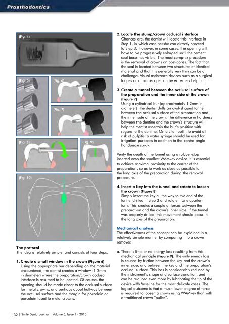
1. Create a small window in the crown (Figure 6)<br />
Using the appropriate bur depending on the material<br />
encountered, the dentist creates a window (1-2mm<br />
in diameter) where the preparation/crown occlusal<br />
interface is assumed to be located. Of course, the<br />
opening should be made closer to the occlusal surface<br />
for metal crowns, and perhaps about halfway between<br />
the occlusal surface and the margin for porcelain or<br />
porcelain fused to metal crowns.<br />
2. Locate the stump/crown occlusal interface<br />
Chances are, the dentist will locate this interface in<br />
Step 1, in which case he/she can directly proceed<br />
to Step 3. However, in some cases, the opening will<br />
have to be progressively enlarged until the cement<br />
seal becomes visible. The most complex procedure<br />
is the removal of crowns on post-cores. The fact that<br />
the seal is located between two structures of identical<br />
material and that it is generally very thin can be a<br />
challenge. Visual assistance devices such as a surgical<br />
loupes or a microscope can be extremely helpful.<br />
3. Create a tunnel between the occlusal surface of<br />
the preparation and the inner side of the crown<br />
(Figure 7)<br />
Using a cylindrical bur (approximately 1.2mm in<br />
diameter), the dentist drills an oval-shaped tunnel<br />
between the occlusal surface of the preparation and<br />
the inner side of the crown. The difference in hardness<br />
between the dentine and the crown’s structure will<br />
help the dentist ascertain the bur’s position with<br />
regard to the dentine. On a vital tooth, to avoid all<br />
risk of pulpitis, a water syringe should be used for<br />
irrigation purposes in addition to the contra-angle<br />
handpiece spray.<br />
Verify the depth of the tunnel using a rubber-stop<br />
inserted onto the smallest WAMkey device. It is essential<br />
to achieve maximal proximity to the center of the<br />
preparation, so as to work as close as possible to<br />
the long axis of the preparation during the removal<br />
procedure.<br />
4. Insert a key into the tunnel and rotate to loosen<br />
the crown (Figure 8)<br />
Simply insert the key all the way to the end of the<br />
tunnel drilled in Step 3 and rotate it one quarterturn.<br />
This creates a couple of forces between the<br />
preparation and the crown’s inner side. If the tunnel<br />
was properly drilled, this movement should occur in<br />
the long axis of the preparation.<br />
Mechanical analysis<br />
The effectiveness of the concept can be explained in a<br />
relatively simple manner by comparing it to a crown<br />
remover.<br />
a. There is little or no energy loss resulting from this<br />
mechanical principle (Figure 9). The only energy loss<br />
is caused by friction between the key and the crown’s<br />
inner side, and between the key and the preparation’s<br />
occlusal surface. This loss is considerably reduced by<br />
the instrument’s shape and surface condition, and<br />
can be reduced even more by lubricating the tip of the<br />
device with Vaseline for the most delicate cases. The<br />
logical outcome is that a much lower degree of force<br />
is required to loosen a crown using WAMkey than with<br />
a traditional crown “puller”.<br />
b. As opposed to crown removers, the forces are<br />
essentially exerted in the axis of the preparation, 5<br />
provided that the tunnel between the crown and the<br />
preparation was drilled as close as possible to the<br />
center of the preparation. Thus, when the couple<br />
of forces go into action, the crown, propelled from<br />
its center, is free to “choose” its trajectory (Figure<br />
10). And so it follows the path of least resistance.<br />
Combined with the fact that there is little to no energy<br />
loss, this means that crowns can be removed with very<br />
little effort.<br />
c. No trauma for the ligament: Contrary to crown<br />
removers, pressure – not traction – is exerted on the<br />
ligament. The patient therefore enjoys maximum<br />
comfort during the procedure. In most cases, no<br />
anesthesia is required.<br />
d. No risk for buildups. The crown is removed thanks to<br />
a couple of forces exerted between the preparation<br />
and the crown. In the case of restorations, the<br />
pressure is applied to the buildup apically, thus<br />
eliminating all risk of loosening it.<br />
Advantages of the device<br />
The advantages of this concept stem from what we<br />
described above.<br />
1. Quick and simple<br />
The device is very easy to use. Two or three uses are<br />
enough to become familiar and comfortable with the<br />
concept. In general, one-and-a-half to two minutes<br />
suffice to remove a crown. Only full-metal or porcelain<br />
fused to metal crowns can sometimes take a bit longer<br />
as the dentist must first locate the cement seal. Removal<br />
of ceramic crowns can also be delicate if one wants to<br />
keep the ceramic fully intact.<br />
2. Efficiency<br />
Based on what we explained above, this concept offers<br />
unprecedented efficiency. Nevertheless, one limitation<br />
must be mentioned: anterior teeth. Because of their<br />
configuration, it is generally not possible to use this<br />
method to remove crowns from anterior teeth. In all<br />
other cases, users frequently report a high success<br />
rates, even when used on the most modern cementing<br />
products.<br />
3. Little to no risk<br />
The innocuousness of this device stems from what we<br />
described above. The forces exerted are reduced to<br />
a minimum and are applied to the long axis of the<br />
preparation, 6 with pressure applied apically to the<br />
abutment tooth.<br />
4. Less wear and tear on rotary instruments:<br />
This varies depending on the type of alloy. Obviously,<br />
dentists who frequently remove prosthetic devices made<br />
of a non-precious alloy or a more recent material (e.g.<br />
zirconium) will be more swayed by this argument.<br />
5. Reuse of the crown or bridge<br />
The most important parts of the crown are not altered. If<br />
the dentist does not modify the margin of the abutment,<br />
and the crown still fits the abutment, then a simple repair<br />
will enable the crown to fulfill all of its original functions.<br />
This can be an advantage, particularly in the following<br />
cases:<br />
• Immediate reuse of the removed crown when the visit<br />
does not allow enough time to fabricate a temporary<br />
crown.<br />
• Canal retreatment procedures performed through<br />
a crown are often more delicate than if the crown is<br />
removed (improved visibility and access to the canal).<br />
When the outcome of the treatment is uncertain,<br />
permanent or long-term reuse of the crown (18-24<br />
months) can be an effective transitional solution. 4,7-10<br />
• Bridges with partial detachment: If a bridge becomes<br />
loose on one abutment without posing any particular<br />
adjustment issues, reusing it can be a worthwhile<br />
alternative and compromise for the patient. 5<br />
• Long bridges can be temporarily reused following a<br />
rebase procedure, while adjustments are made to the<br />
various abutment restorations.<br />
In most, if not all cases, the temporary reuse of the<br />
crown is clearly a major advantage.<br />
For all of these reasons, WAMkey represents a major<br />
advancement compared to all previous techniques.<br />
Clinical Case<br />
Extensive work was planned to be performed for the<br />
patient. A complete maxillary prosthesis must be made,<br />
and for obvious biological and cosmetic reasons (Figures<br />
11,12) the lower bridge must be removed. The nickelchrome<br />
framework features a long support span, in<br />
one block, with no anterior abutments. Before removal,<br />
we cannot be certain of the condition of the six existing<br />
abutments or whether it will be possible to save them.<br />
Salvaged abutments will need to be endodontically<br />
retreated, rebuilt and reinforced with fiber posts. Once<br />
rebuilt, and depending on their mechanic potential, a<br />
fixed prosthetic solution will be considered, such as a<br />
tooth-supported bridge or an implant-tooth supported<br />
prosthesis. A single visit, even if very long, will not be<br />
enough to retreat and restore all six teeth and make a<br />
temporary, reinforced 12-unit bridge.<br />
We decided to remove the fixed bridge, assess the<br />
clinical situation, apply periodontal treatment, minimally<br />
adjust the marginal limits and rebase the original bridge<br />
for temporary use until the endodontic therapy could be<br />
completed.<br />
| 32 | <strong>Smile</strong> <strong>Dental</strong> <strong>Journal</strong> | Volume 5, Issue 4 - 2010 <strong>Smile</strong> <strong>Dental</strong> <strong>Journal</strong> | Volume 5, Issue 4 - 2010 | 33 |