Signal Processing - Snell
Signal Processing - Snell
Signal Processing - Snell

Create successful ePaper yourself
Turn your PDF publications into a flip-book with our unique Google optimized e-Paper software.
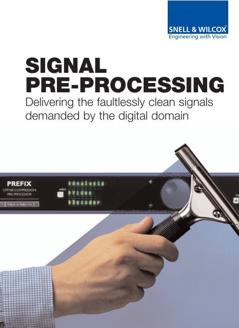
SIGNAL<br />
PRE-PROCESSING<br />
Delivering the faultlessly clean signals<br />
demanded by the digital domain
<strong>Signal</strong> Pre-processing<br />
In an increasingly digital world, the need for clean<br />
video signals has never been greater. Digital signal<br />
paths within a facility are capable of passing video<br />
information with faultless accuracy. For the best<br />
possible results, digital signal paths in turn demand<br />
inputs that are as near faultless as possible.<br />
Moreover, digital broadcasting can only achieve<br />
the high degree of compression that bandwidth<br />
limitations demand if the signal inputs to a digital<br />
encoder are as free from noise and artifacts as<br />
possible. The answer is efficient, accurate<br />
pre-processing of the video signal to remove as<br />
many of the unwanted elements as possible,<br />
without degrading the signal itself*.<br />
*For further information regarding types of noise and filtering options see page 12
<strong>Snell</strong> & Wilcox is uniquely qualified to provide the<br />
definitive solutions to signal pre-processing needs.<br />
As a recognized leader in digital signal processing for<br />
many years, the company’s research has resulted in<br />
many ground-breaking advances and has gained the<br />
company numerous awards from around the world.<br />
RollCall Control<br />
In the increasingly complex world of digital<br />
television, simplicity and ease of control are<br />
of paramount concern.<br />
That’s why we’ve developed RollCall, the<br />
intelligent control and monitoring system.<br />
RollCall is a powerful solution that meets all<br />
your control and monitoring requirements. It<br />
offers a range of control strategies, from<br />
simple panel control to a sophisticated suite<br />
of PC applications.<br />
RollCall provides the operator with an<br />
automatic update of a system’s status at all<br />
times. It also offers monitoring and logging,<br />
with the ability to react automatically to<br />
events as well as to record these for<br />
diagnostic analysis.<br />
RollCall integrates <strong>Snell</strong> & Wilcox products<br />
(stand-alone as well as modular) onto a single<br />
network. It is also designed to enable simple<br />
interfacing with third party systems.
Prefix CPP100 and CPP200<br />
Compression Pre-processors<br />
Interactive capability enhances<br />
accuracy<br />
Prefix’s versatility is enhanced by its additional<br />
ability to work interactively with suitably<br />
equipped compression engines. Details of the<br />
incoming video signals such as 3:2 pull-down<br />
sequences from telecines and video edit<br />
information can be extracted and then<br />
passed-on to the compression engine. This<br />
information can then be used to ‘steer’ the<br />
compression device by alerting it to<br />
forthcoming characteristics of the input signal.<br />
Awareness of these characteristics greatly<br />
increases the accuracy of the subjective<br />
decisions made by the compression engine,<br />
thereby improving the overall compression<br />
performance at any given bit rate.<br />
This ability to work interactively with the<br />
compression engine, or independently from it,<br />
combined with its processing power make the<br />
Prefix the most powerful and comprehensive<br />
system of its kind.<br />
‘Prefix’ from <strong>Snell</strong> & Wilcox is the proven solution to<br />
the needs of MPEG2 pre-processing. Available with<br />
audio insertion capability (CPP200) or without<br />
(CPP100), this multi-award winning design will<br />
ensure the lowest level of noise in any MPEG2<br />
source signal. The result? Improved picture quality<br />
for the viewer, and greatly reduced bandwidth<br />
requirement for the broadcaster.<br />
MPEG compression demands extremely high quality inputs if<br />
artifacts are to be minimized. A compressor may work well<br />
enough on clean signals from a component digital recorder,<br />
but real-world signals from analog, composite or film sources<br />
can cause serious problems.<br />
MPEG achieves the required data compression by transmitting<br />
only the differences between successive pictures. Noise is<br />
thus a particular problem in MPEG encoding since it causes<br />
changes from one picture to the next that are random - changes<br />
that the compressor will try to encode, using up valuable data<br />
capacity. With the powerful noise reduction and pre-processing<br />
of a Prefix, a compressor can more fully utilize the bandwidth<br />
that is available to it. The result is improved quality pictures<br />
that require less bandwidth.<br />
Prefix operates in the component 4:2:2 domain and has a<br />
number of distinct filters, each ‘tuned’ to remove a specific<br />
type of noise.<br />
Because of its sub-sampling operation, MPEG cannot<br />
transmit some very high frequency information.
Moreover, high frequency aliasing can occur without adequate<br />
pre-filtering. Prefix incorporates a range of 3D<br />
de-enhancement filters, which allow selective reduction of high<br />
frequencies prior to the encoder.<br />
As well as reducing noise, Prefix contains a sophisticated<br />
detail enhancer for pictures that have been band limited.<br />
The enhancer works to sharpen detail in the picture without<br />
introducing the ringing or overshoots normally associated with<br />
such enhancement. The level of enhancement can be<br />
subjectively selected by the user to suit the bandwidth of the<br />
program material, with coring facilities to ensure that low level<br />
noise is not enhanced.<br />
Prefix - typical applications<br />
Prefix filter types<br />
• Recursive (motion adaptive temporal filter)<br />
reduces noise in stationary areas without<br />
loss of horizontal and vertical resolution<br />
• Semi-transversal (on recursive filter<br />
output only) – improves performance of<br />
recursive filter at scene changes and<br />
around moving objects<br />
• Median (adaptive median filter) –<br />
effective for elimination of impulse noise<br />
such as drop-out<br />
• Spatial (2D median filter) – spatial<br />
noise reducer<br />
• Linear filters brickwall low pass filters –<br />
provide good band-limiting for MPEG<br />
encoders using half resolution processing;<br />
ten sets of Gaussian low-pass filters<br />
correct materials that have been<br />
previously boosted or enhanced; five sets<br />
of Gaussian high-pass filters provide<br />
variable correction of high level luminance<br />
from analog VTRs<br />
• Scratch filter – fully automatic key<br />
generation and correction; algorithm<br />
can be biased for specific scratch<br />
characteristics<br />
• Enhancer – enhance, MPEG de-enhance,<br />
decoder matching and video mode<br />
(these cannot be used in combination)
Prefix<br />
Essential Picture Conditioning<br />
Prefix CPP100/200 features:<br />
• Essential picture conditioning to improve<br />
compression ratios and optimize<br />
bandwidth usage in MPEG encoding<br />
• Adaptable for picture source type – film,<br />
lowband video, etc<br />
• Full range of noise and artifact reduction<br />
filters, including recursive, median,<br />
transversal and brick wall to ensure optimal<br />
pre-conditioning of any input signal<br />
• Two composite decoder options: standard<br />
decoder or advanced multi-phase decoder<br />
featuring ‘Golden Gate’ technology<br />
• Comprehensive signal analysis and noise<br />
reduction ensures optimum compression<br />
• Gives significant quality improvements on<br />
archive material, especially when the<br />
archive source is lowband, or contains<br />
dropouts and the like<br />
• ‘Steers’ the compression engine by<br />
supplying ‘flagged’ information on picture<br />
characteristics the encoder can use to<br />
improve the efficiency of encoding decisions<br />
• Includes frame synchronization with full<br />
horizontal and vertical offset control<br />
• Decoder options allow decoding to be<br />
selected to suit the application<br />
• Digital audio embedding and delay (from<br />
an analog source - CPP200 only)<br />
• All VITS lines controllable (pass or blank)<br />
• Embedded audio is passed seamlessly<br />
through unit<br />
• All digital input formats supported<br />
Audio Insertion (CPP200)<br />
In its 2RU high CPP200 form, Prefix can be supplied with an<br />
additional audio processor card to provide AES/EBU standard<br />
embedding of analog audio inputs into the digital output<br />
signal. The same card also provides automatic delay<br />
compensation to ensure perfect video/audio sync.<br />
Up to four channels (usually two stereo pairs) are analog-todigital<br />
converted by the audio processor card, and formatted to<br />
the AES specification. A phase-locked loop circuit is then used<br />
to lock the 48kHz sampling rate of the audio signal to the video<br />
output from the pre-processor. Finally, the video and formatted<br />
audio are serialized to provide two 270Mbit/sec output signals in<br />
accordance with the SMPTE 259M-C Rec.601 specification.<br />
Filter memories<br />
In addition to its user-selectable filter options, Prefix has a<br />
pre-set memory of nine combinations of filter operation and level<br />
stored in memory to provide optimal pre-processing for common<br />
source material conditions:<br />
• Film artifacts<br />
• Video artifacts<br />
• Film – MPEG bit rate low<br />
• Film – MPEG bit rate medium<br />
• Film – MPEG bit rate high<br />
• Film and video artifacts<br />
• Video – MPEG bit rate low<br />
• Video – MPEG bit rate medium<br />
• Video – MPEG bit rate high<br />
• Wide range of test patterns
Noise<br />
A Universal Problem<br />
“Noise” is a term used in the general sense to<br />
describe any unwanted signal that has become part<br />
of the video waveform. For a noise reducer,<br />
Sources of Noise<br />
Noise can be broadly categorized into two types, depending on<br />
the source: video noise and film-related noise.<br />
however, “noise” does not exist in this generalized<br />
sense: it has to be categorized according to<br />
its nature, and suitable corrective measures<br />
devised for each category.<br />
Video noise occurs as one of four main types:<br />
1. Electronic <strong>Processing</strong> Noise: in transmission systems,<br />
broadband noise having a true random behavior is encountered.<br />
In transmission systems, for example, broadband noise having a<br />
true random behavior is frequently encountered, and there are<br />
many other types and sources of unwanted signal elements.<br />
Poor quality composite decoding can result in problems of<br />
residual subcarrier and cross-color, analog VCRs can produce<br />
2. Decoding Artifacts: a picture decoded from a composite<br />
source may contain unwanted signals that are a function of the<br />
picture structure and processing. Decoding artifacts include<br />
residual subcarrier and cross color, the result of poor quality<br />
composite decoders.<br />
crosstalk. Tape dropout, damaged film and faults in digital links<br />
can all add their contributions in the form of impulse noise.<br />
3. VTR Noise: the main storage medium in broadcast television<br />
is tape. This produces several types of noise, including crosstalk<br />
Worse still, noisy signals can bring with them the problems of<br />
timebase error - either from VCRs or from the effects of<br />
transmission noise on sync pulse edges.<br />
from analog VCRs and dropouts as well as general broadband<br />
noise. In practice, noisy signals from analog VTRs are often<br />
accompanied by timebase errors that result from the VTR’s<br />
operation, or from transmission noise affecting the sync edges.<br />
As a consequence, <strong>Snell</strong> & Wilcox engineers have expended<br />
considerable effort to develop new approaches to noise<br />
reduction techniques and products.<br />
4. Digital Errors: faulty digital links can cause unwanted impulse<br />
signals caused by bit-dropouts. Low carrier-to-noise levels in<br />
FM links can result in impulse noise such as the ‘sparkles’<br />
With the advent of lower cost silicon and dynamic random<br />
often found in satellite signals.<br />
access memories (DRAM) in particular, new generations<br />
of powerful noise reducers are increasingly accessible to<br />
the television and related industries. <strong>Snell</strong> & Wilcox offers a wide<br />
range of real-time noise reducer and image enhancer<br />
products to choose from depending on the application.<br />
There are two principal sources of noise and artifacts in video<br />
from film originated material.<br />
1. Film Structure: can produce background noise over the<br />
complete frame. This is a result of the film grain, the individual<br />
grains of dye being seen as a background noise pattern. Film<br />
Noise reducers now operate in the digital component domain<br />
and provide repeatable and reliable performance.<br />
makers try to use finer grain, slower speed film stock to<br />
overcome the problem; however if 16mm film or large amounts<br />
of zoom are used then this effect will still be visible.
2. Film defects: the most common forms of film defects are dirt<br />
and scratches. Most post-production houses have extensive<br />
film cleaning facilities to remove dirt. However random dirt can<br />
appear and can be difficult to deal with.<br />
Scratches are the result of damage to the film emulsion<br />
due to poor handling or faulty replay equipment, and are<br />
a particularly obvious and thus irritating form of noise.<br />
Noise Reduction Filters and Their Operation<br />
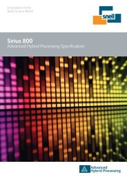
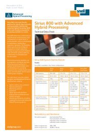
Recursive Filter Recursive filtering is a widely used technique for<br />
the reduction of random video noise such as camera and tape<br />
noise. Recursive filters reduce noise by averaging successive<br />
pictures over a period of time (Figure 1), using delays of<br />
exactly one frame to create, in effect, a temporal low-pass<br />
filter. Noise can be reduced in stationary areas without loss of<br />
spatial (vertical and horizontal) resolution.<br />
Bitrate Management<br />
To the digital broadcaster, the bandwidth<br />
available for transmission is a precious<br />
asset. Making the best possible use of<br />
this asset requires careful management of<br />
the signals being transmitted to ensure<br />
the bitrate for any given signal is high<br />
enough to ensure good picture quality,<br />
but not so high as to be wasteful.<br />
Compression encoders cannot differentiate<br />
what is wanted in a signal from what is<br />
not: any noise or artifacts in the signal feed<br />
will be encoded at the compression stage.<br />
Not only does this result in poorer quality<br />
pictures for the viewer, it results in a<br />
transmission bitrate greater than that<br />
needed - often much greater.<br />
Whether the problem is video noise,<br />
composite decoding artifacts,<br />
unsteadiness, excess enhancement or<br />
any other impairment, accurate and<br />
appropriate conditioning of the signal<br />
prior to compression can provide<br />
significant bitrate savings.<br />
Figure 1. Temporal Recursive Filter
14<br />
Noise<br />
A Universal Problem<br />
Although temporal recursive filters offer considerable levels of<br />
noise reduction, sophisticated control logic is necessary to<br />
ensure that picture detail is retained at higher noise settings.<br />
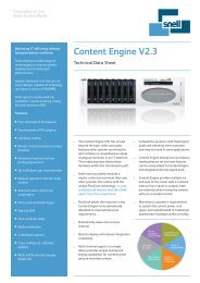
Median Filter: Median filters are effective at removing impulse noise<br />
such as the ‘sparkles’ often encountered in satellite transmissions.<br />
They operate by rank-filtering pixels from an odd number of<br />
aperture points around the target pixel to give a median value. The<br />
In particular, analysis of the noise floor level is necessary to set<br />
movement thresholds which allow maximum discrimination<br />
between noise and movement. In addition, the recursive filter<br />
provides settings for luminance and chrominance, bias and<br />
threshold.<br />
aperture set may utilize the surrounding points from the same field<br />
or, more usually, a combination of pixels from the current and<br />
adjacent fields or frames (Figure 2). When a pixel is judged to be in<br />
error, it is replaced by the median value of its aperture set; pixels<br />
judged not to be in error remain unaltered.<br />
Semi-transversal Filter: The semi-transversal is a unique,<br />
<strong>Snell</strong> & Wilcox patented design that operates in conjunction<br />
with the recursive filter to increase its effectiveness with moving<br />
areas and after scene changes.<br />
The algorithm used is very specific to the areas of the picture<br />
that are filtered, and uses both spatial and temporal gradient<br />
information to determine whether a pixel has impulse noise<br />
characteristics. In operation, the filter automatically detects<br />
impulse noise for black, white, long or short (film or dust)<br />
drop-outs, and requires only level settings from the user.<br />
Unlike tradition transversal filters in its design, the semitransversal<br />
filter operates by selecting the most appropriate<br />
outputs from a chain of picture stores at the output of the<br />
recursive filter. An algorithm is used to determine which of the<br />
stores contains the highest level of noise-reduced picture.<br />
Spatial Filter: Spatial filtering involves the use of an aperture<br />
comprising adjacent pixels from the same field. Spatial median<br />
filters can be very effective at reducing impulse noise resulting<br />
from film dust or small drop-outs; they can also be highly<br />
The <strong>Snell</strong> & Wilcox semi-transversal filter is able to measure<br />
effective as Gaussian noise reduction filters.<br />
the recurrence of noise and delay the output of the recursive<br />
filter by up to three frames. Operating on a pixel-by-pixel<br />
basis, the overall level of noise in a typical picture is<br />
maintained at a more uniform level and is less dependent on<br />
movement. As the semi-transversal filter operates in<br />
conjunction with the recursive filter, it cannot be used on its<br />
own. Operation of the filter is entirely automatic, requiring no<br />
user adjustments or settings to be made.<br />
The spatial filter operates by median filtering a small kernel of<br />
adjacent pixels and then comparing the median filtered pixel<br />
value with the current pixel. The spatial filter has three level<br />
settings used to vary the comparison threshold, and thus, in<br />
effect, to set the balance between the level of noise<br />
suppression and the preservation of fine detail. Spatial filtering<br />
is typically used in conjunction with temporal filter types such<br />
as recursive and semi-transversal to boost the overall level of<br />
noise reduction.
15<br />
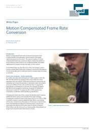
Figure 2. Spatial and Temporal Median Aperture Set<br />
Spatial and Temporal Median Aperture Set<br />
Vert<br />
Frame n-1<br />
Frame n<br />
Gaussian Low-pass: Units such as the NRS500 and the CPP<br />
range provide ten sets of linear Gaussian low-pass filters. These<br />
Temporal<br />
point<br />
Horiz<br />
Frame n+1<br />
can be used to attenuate high frequencies to correct material<br />
that has been previously enhanced or boosted, and to reduce<br />
Spatial<br />
points<br />
high frequency noise.<br />
Temporal<br />
point<br />
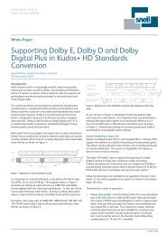
Figure 3. 2.8MHz Brickwall Filter with Available Boost<br />
2.8MHz Brickwall Filter with Available Boost<br />
Time<br />
Gaussian High-pass: Five sets of linear Gaussian high-pass<br />
filters provide variable correction of high-frequency luminance<br />
that may have been attenuated by faulty distribution links or by<br />
analog VTR processes.<br />
Amplitude<br />
Scratch Filter: The scratch filter detects and eliminates the<br />
effects of film scratches of variable length and contrast, whether<br />
they are black, white or both. It does so while ensuring there is<br />
no loss of quality in areas of the picture unaffected by scratches.<br />
To maximize the benefits of the filter, it is provided with a<br />
selection of filter strengths.<br />
0<br />
1 2 3<br />
Frequency (MHz)<br />
4 5 6<br />
Enhancement: Restores the perceived sharpness of an image<br />
by adding a correction signal. The correction is derived from<br />
information in the incoming signal and is used to sharpen the<br />
Brickwall Low-pass: This is a linear filter providing ranges from<br />
4.2 to 2.5MHz, and providing effective band-limiting facilities<br />
for MPEG encoders that use half resolution processing. This<br />
filter also provides variable peaking or boosting at each of the<br />
selected cut-off frequencies (Figure 3). The overall perception<br />
edges and boost peaks. Careful design ensures that it does<br />
so without producing unnaturally sharp results or the artifacts<br />
associated with other enhancers. The enhancer has separate<br />
controls for mode enhance, luminance, chrominance<br />
and coring.<br />
of picture sharpness can be raised by boosting prior to<br />
brickwall filtering.<br />
The coring function is a window with an adjustable threshold that<br />
can be altered according to the level of noise in the incoming<br />
The filter provides an additional set of extra low-pass settings<br />
where even greater band-limiting is required, with cut-off<br />
frequencies from 2.4 to 0.9MHz.<br />
signal. The coring levels can be adjusted according to the quality<br />
of the input pictures: the higher the coring level, the less the<br />
noise is enhanced.
16<br />
Prefix and NRS500 Filter Combinations for Optimum Solutions-Typical Examples<br />
Application<br />
Recursive<br />
Semi<br />
Transversal<br />
Median<br />
Spatial<br />
Linear<br />
Scratch<br />
Enhancer<br />
1<br />
Satellite Noise<br />
Y - Med<br />
C - Med<br />
Threshold - Auto<br />
Bias - 0<br />
On<br />
Level - Med 3<br />
Off<br />
Mode: Off<br />
Off<br />
Off<br />
2<br />
Film Artifacts<br />
Y - Min<br />
C - Med<br />
Threshold - Auto<br />
Bias - 0<br />
On<br />
Level - Med 4<br />
Y - Min<br />
C - Med<br />
Mode: Off<br />
Strength - Med<br />
Contrast - Low+Med<br />
Length - Long<br />
Type - Both<br />
Mode: Enhance<br />
Y - Min<br />
C - Min<br />
Y Core - Min<br />
C Core - Min<br />
3<br />
Video Artifact<br />
Y - Med<br />
C - X Color<br />
Threshold - Auto<br />
Bias - 0<br />
On<br />
Level - Med 3<br />
Y - Min<br />
C - Max<br />
Mode: Off<br />
Off<br />
Off<br />
4<br />
Film & Video<br />
Artifacts<br />
Y - Med<br />
C - X Color<br />
Threshold - Auto<br />
Bias - 0<br />
On<br />
Level - Max 5<br />
Y - Med<br />
C - Max<br />
Mode: Brickwall<br />
Cutoff - 3.2MHz<br />
Boost - 0dB<br />
Strength - Med<br />
Contrast - Low+Med<br />
Length - Long<br />
Type - Both<br />
Off<br />
Though designed individually to counteract different types of noises, filters do not have to be used in isolation from each other. In<br />
practice, they can used in combination to provide the optimum solution to the imperfections of real signals.<br />
All filter types in the <strong>Snell</strong> & Wilcox range of signal pre-processing equipment are provided with a full range of adjustments and<br />
settings to ensure the highest level of noise reduction without unnecessary impairment of the picture quality.
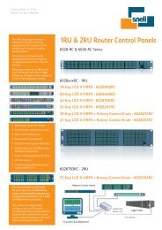
Rear panel connections<br />
17<br />
COMP A<br />
LOOP<br />
COMP B<br />
LOOP<br />
ANALOGUE INPUTS<br />
Y/G<br />
Component<br />
C<br />
U/B<br />
MS A B<br />
Component<br />
V/R<br />
SMPTE 259M INPUTS<br />
PARALLEL COMPOSITE<br />
Serial<br />
Composite<br />
EDH/Error<br />
Audio Dly<br />
REFERENCE<br />
SMPTE 259M-C OUTPUTS<br />
LOOP OUT OUT<br />
SYSTEM<br />
SERIAL<br />
NET<br />
SYSTEM<br />
AUX<br />
AC I/P<br />
AUTO<br />
SELECT<br />
88-256V<br />
45-60Hz<br />
FUSE<br />
3.15A<br />
Prefix CPP100 Compression Pre-processor<br />
ANALOGUE INPUTS<br />
COMP A<br />
C<br />
LOOP<br />
COMP B<br />
Y/G<br />
COMPONENT<br />
Pb/B<br />
MS<br />
Pr/R<br />
ANALOGUE AUDIO IN<br />
1<br />
Push<br />
Push<br />
2<br />
EDH<br />
ERROR<br />
REF<br />
SYSTEM<br />
SERIAL<br />
NET<br />
AUX<br />
SYSTEM<br />
90v - 250v<br />
Max Current 1.8A<br />
50/60Hz<br />
FUSE: 2.5 A (T)<br />
<strong>Snell</strong> & Wilcox Ltd<br />
Model : PREFIX<br />
Made in Havant, England<br />
LOOP<br />
SMPTE 259M INPUTS<br />
PARALLEL COMPOSITE<br />
259M-AB<br />
A<br />
259M-C<br />
B<br />
259M-C<br />
Push<br />
3<br />
Push<br />
4<br />
LOOP<br />
SMPTE 259M - C OUTPUTS<br />
PROGRAM<br />
MONITOR<br />
F<br />
U<br />
S<br />
E<br />
Prefix CPP200 Compression Pre-processor with Audio Insertion
Technical Profiles<br />
Prefix<br />
CPP100 and CPP200<br />
Compression<br />
Pre-processors<br />
<strong>Signal</strong> Inputs<br />
Composite Loop A: Analog loop-through<br />
input, 1V pk to pk,<br />
75 ohm impedance<br />
Input Return Loss: Better than 40dB at<br />
4.43MHz (standard<br />
decoder); better than<br />
35dB at 5.5MHz<br />
(advanced multi-phase<br />
decoder)<br />
Composite Loop B: Analog loop-through<br />
input, 1V pk to pk,<br />
75 ohm impedance<br />
Input Return Loss: Better than 40dB at<br />
4.43MHz (standard<br />
decoder); better<br />
than 35dB at 5.5MHz<br />
(advanced multi-phase<br />
decoder)<br />
Digital Component: SMPTE 259M-C A input<br />
Input<br />
SMPTE 259M–C B input<br />
Input Return Loss: Better than 17dB at<br />
270MHz<br />
Reference Loop: Analog loop-through<br />
input, 1V pk to pk,<br />
75 ohm impedance<br />
<strong>Signal</strong> Outputs – CPP100<br />
SMPTE 259M-C 2 x program outputs<br />
1 x monitor output<br />
Output Return Loss Better than 17dB at<br />
270MHz<br />
<strong>Signal</strong> Outputs – CPP200<br />
SMPTE 259M C 2 x program outputs<br />
with embedded AES<br />
audio in channel<br />
positions 1, 2, 3, 4<br />
Output Return Loss Better than 17dB at<br />
270MHz<br />
Standard Decoder (optional)<br />
Digital <strong>Processing</strong>: Minimum 10-bit<br />
processing throughout<br />
A to D Conversion: Analog composite input<br />
is sampled using 10-bit<br />
ADC, twice oversampled<br />
Luminance/<br />
Chrominance<br />
Separation:<br />
BLO Operating<br />
Range:<br />
Video Gain:<br />
Chroma Gain:<br />
Black Level:<br />
Color Filters:<br />
NTSC/PAL-M<br />
Pedestal<br />
NTSC Hue:<br />
Picture Position:<br />
Decode Mode:<br />
Comb Mode:<br />
Vertical Adaption:<br />
VITS<br />
and digitally<br />
filtered/decimated<br />
Symmetrical multistandard<br />
adaptive<br />
field comb<br />
Dual 263H NTSC, PAL-<br />
M Dual 312H PAL-I,<br />
PAL-N<br />
±100Hz<br />
±3dB in 0.1dB steps<br />
±6dB in 0.05dB steps<br />
±20mV, in 2mV steps,<br />
manual or automatic<br />
tracking<br />
Wide/Medium/Narrow<br />
On: Input has a pedestal<br />
Off: Input does not have<br />
a pedestal<br />
±180° in 1°steps<br />
±600ns<br />
Enable or disable<br />
Y/C separation<br />
Non-adaptive,<br />
adaptive (default)<br />
Chrominance ‘Hanover<br />
bars’ suppression:<br />
On – adaptive vertical<br />
filter (default)<br />
Off – non-adaptive<br />
vertical filter<br />
Individual line controls or<br />
group control for<br />
blanking/passing of VITS<br />
lines; 625 composite<br />
format: lines 6 to 22 and<br />
318 to 335, 525<br />
composite format: lines<br />
9 to 20 and 272 to 282<br />
Advanced Multi-phase Decoder (optional)<br />
Digital <strong>Processing</strong> Minimum 10-bit<br />
processing throughout<br />
A to D Conversion Analog composite input<br />
is sampled using 10-bit<br />
ADC<br />
Composite Formats NTSC, PAL, PAL-M,<br />
PAL-N<br />
Video Gain 0 to 117% in 1% steps<br />
Chroma Gain 0 to 200% in 1% steps<br />
NTSC Pedestal Pedestal On/Off<br />
NTSC Hue -180 to +179° in 1°<br />
steps<br />
Picture Position -600 to +600ns in<br />
7.4ns steps<br />
Comb Mode<br />
VITS<br />
Pre-processor<br />
Recursive Filter<br />
Semi-Transversal<br />
Filter<br />
Median Filter<br />
Spatial Filter<br />
9 x comb modes<br />
available<br />
Studio 1, Studio 2,<br />
Ldisk, VHS, Still, Simple<br />
1, Simple 2, Line<br />
Individual line controls or<br />
group control for<br />
blanking/passing of VITS<br />
lines 625 composite:<br />
lines 6 to 22 and 319 to<br />
335 525 composite: lines<br />
10 to 20 and 272 to 282<br />
Motion adaptive<br />
asymmetrical temporal<br />
(frame) recursive filter.<br />
Three set levels with<br />
maximum noise<br />
reduction of 12dB<br />
Bias adjustment ±3dB in<br />
approximately 1dB steps<br />
Filter: On/Off<br />
Luminance: Off, Min,<br />
Med, Max Chrominance:<br />
Off, Min, Med, Max<br />
Threshold (noise floor):<br />
Auto, 1 to 15<br />
Operates on recursive<br />
filter output. Reduces<br />
absolute levels of noise<br />
trails in static revealed/<br />
concealed areas, e.g.<br />
after scene changes up<br />
to 4.7dB. Can only be<br />
switched on when<br />
recursive filter is selected.<br />
Filter: On/Off<br />
Adaptive spatial/temporal<br />
median filter<br />
Filter: On/Off<br />
Level: Min 1, Min 2, Med<br />
3, Med 4, Max 5, Max 6<br />
Spatial 2D median filter<br />
Filter: On/Off<br />
Luminance: Off, Min,<br />
Med, Max<br />
Chrominance: Off, Min,<br />
Med, Max
Linear Filter<br />
18 sets of linear 15-tap<br />
low pass brickwall<br />
digital filters<br />
6 sets of linear 15-tap<br />
extra low pass brickwall<br />
digital filters<br />
6 sets of peaking value<br />
for each cut-off<br />
frequency 10 sets of<br />
Gaussian low-pass<br />
filters (no peaking)<br />
5 sets of Gaussian<br />
high-pass filters<br />
Brickwall Low Pass Full bandwidth,<br />
Cut-off<br />
4.2 to 2.5MHz<br />
(-6dB) in 0.1MHz steps<br />
Brickwall Extra 2.4 to 0.9MHz (-6dB) in<br />
Low-pass Cut-off 0.3MHz steps (no<br />
boost)<br />
Boost<br />
None, 1, 2 3, 4.5, 6dB<br />
Gaussian Low-pass -4 to –40dB in 4dB<br />
steps<br />
Gaussian High-pass 1, 2 3, 4.5, 6dB<br />
Scratch Filter Filters of different<br />
strengths for vertical<br />
scratches of variable<br />
contrast, type and<br />
length<br />
Filter: On/Off<br />
Strength: Min, Med, Max<br />
Contrast: Low, Med, High<br />
Length: Any, Long<br />
Type: Black, White, Both<br />
Enhancer Modes Off, Enhance, MPEG<br />
De-enhance, Decoder<br />
Mode, Video Mode<br />
Enhance<br />
Spatial 2D enhancer<br />
utilizing separately<br />
derived, non-linear<br />
and linear edge<br />
detection and<br />
compression<br />
Luminance: Off, Min,<br />
Med, Max<br />
Chrominance: Off, Min,<br />
Med, Max<br />
Luminance Coring: Off,<br />
Min, Med, Max<br />
Chrominance Coring:<br />
Off, Min, Med, Max<br />
MPEG De-enhance Non-adaptive<br />
symmetrical vertical<br />
temporal filter utilizing<br />
±1 field contributions<br />
Luminance: Off, Min,<br />
Med, Max<br />
Chrominance: Off, Min,<br />
Med, Max<br />
Decoder Match Non-adaptive<br />
symmetrical vertical<br />
temporal filter utilizing<br />
±1 field contributions.<br />
Aperture adjusted to<br />
complementary match<br />
decoder comb structure<br />
- line comb, field comb,<br />
other<br />
Video Mode Reduces temporal<br />
bandwidth of video<br />
originated inputs prior<br />
to MPEG2<br />
encoding: Modes 1, 2<br />
Synchronizer Genlock Input/<br />
Reference/Off<br />
Status: Input<br />
Lock/Reference Lock<br />
Horizontal Offset:0 to<br />
1H in 37ns steps<br />
Vertical Offset: 0 to 624H<br />
(625 line standards)<br />
0 to 524H (525 line<br />
standards)<br />
VITS<br />
All On, All Off, Select<br />
individual lines Individual<br />
line controls or group<br />
control for<br />
blanking/passing of VBIS<br />
lines<br />
Advanced Multi-phase<br />
Decoder<br />
625 Standard: 6 to 22<br />
and 319 to 335 525<br />
Standard: 10 to 20 and<br />
272 to 282<br />
Standard Decoder<br />
625 Standard 6 to 22<br />
and 318 to 335 525<br />
Standard 9 to 22 and<br />
272 to 282<br />
Embedded V flag OVD Optional Video<br />
Style (525 line only) Data (1 to 9/264 to 272)<br />
OBD Optional Blanking<br />
Data (1 to 19/264 to 282)<br />
ABD Additional Blanking<br />
Data (20/22) Lines 1 to<br />
22/264 to 282 not<br />
filtered (V flag as OBD)<br />
8-bit Rounding 10-bit to 8-bit rounding<br />
using truncation error<br />
feedback<br />
EDH<br />
Input error detection<br />
and handling<br />
Status: None, Ok, Errors<br />
AP/FF: individual or<br />
linked reset<br />
EDH insertion on two<br />
Program outputs<br />
Key Window Allows split screen<br />
facilities to monitor<br />
effects of digital<br />
filtering applied to the<br />
key area only<br />
Select: Off, H-split,<br />
V-split, Box, User, H-<br />
repeat User: user-defined<br />
key window coordinates<br />
X1, Y1, X2, Y2<br />
Invert: inversion of<br />
selected key window<br />
Border: selects the<br />
border shade around the<br />
key window: Off, Black,<br />
White<br />
Event Logging Enables the user to<br />
monitor events using<br />
RollCall PC log<br />
reviewer<br />
Pattern<br />
Internal test patterns:<br />
Black, EBU bars, Y<br />
ramp, UV ramp, Y<br />
sweep, UV sweep,<br />
Bowtie, Full bars<br />
On Fail<br />
This sets the default for<br />
the unit when the input<br />
signal fails: SDI B, Video<br />
(comp. input), Freeze<br />
(SDI input),<br />
Message, any of the test<br />
patterns<br />
Panel Display RollCall “shoebox”<br />
panel display information:<br />
Normal,<br />
Recursive, Median,<br />
Spatial, Enhancer, Linear,<br />
EDH Check, Network,<br />
Auto-loop<br />
On-screen Using monitor output:<br />
Display<br />
None, System, Filters,<br />
(not available Decoder<br />
with CPP200)<br />
Memory Store User-defined memory,<br />
slots 1 to 8<br />
Memory Recall User-defined memories<br />
(User) 1 to 8,<br />
Memory Recall Recall preset or<br />
(Preset)<br />
factory setmemories<br />
Memory Set Name Set memory name<br />
(user-defined) 1 to 8;<br />
10 characters of ASCII<br />
character set
Technical Profiles<br />
Audio Processor (CPP200 only)<br />
Analog Audio In 4 x channels XLR analog<br />
audio inputs; 10kOhm<br />
impedance, balanced<br />
Reference Level Nominal input level<br />
+4dBu<br />
A to D Conversion 18-bit resolution, 64<br />
times oversampled<br />
Input Headroom Adjustable, nominally<br />
+18dB<br />
Frequency Range 20Hz to 20kHz, ±1dB<br />
Total Harmonic Less than 0.015% at<br />
Distortion 1kHz<br />
<strong>Signal</strong> to Noise Better than 100dB, 20Hz<br />
to Ratio 20kHz<br />
Input Dynamic 106dB<br />
Range<br />
Phase Difference Less than 1° at 1kHz<br />
Between Channels<br />
Cross-talk Less than 75dB at<br />
15kHz<br />
Channel Level Less than 0.5dB<br />
Difference<br />
Digital Audio 48k samples/s<br />
Sample Rate<br />
Serial Digital Pair of 32 bit<br />
synchronous<br />
Format<br />
serial channels<br />
Delay Adjustment -1, 0, 1 to 10 fields in<br />
0.25 field steps<br />
Audio Level Mute, -95.5 to +31.5dB<br />
Adjustment in 0.5dB steps<br />
Test Tone Individually selectable<br />
on channels 1 to 4,<br />
digitally generated at<br />
+4dBu level<br />
AES Group Group 0, 1, 2, 3<br />
SMPTE 259M-C 2 x program outputs with<br />
Outputs<br />
embedded AES audio in<br />
channel positions 1 to 4<br />
Output Return Loss Better than 17dB at<br />
270MHz<br />
Communications<br />
Serial Net<br />
RollCall BNC<br />
System<br />
Communication<br />
Auxiliary<br />
Proprietary <strong>Snell</strong> & Wilcox<br />
interface multi-drop<br />
via BNC T network<br />
9-pin D-type, RS422<br />
slave<br />
9-pin D-type, RS422<br />
master<br />
Power<br />
Input Voltage 90 to 250V, 50/60Hz,<br />
1.2A<br />
Consumption 100VA maximum<br />
Mains Fuse Rating 2.5A(T)<br />
Mechanical – CPP100<br />
Temperature Rating 0 to 30°C operating<br />
Cooling<br />
Filtered axial fan; frontto-rear<br />
air flow<br />
Case Type 1RU rack mounting<br />
Dimensions 483 x 535 x 45mm<br />
(w x d x h)<br />
Mechanical – CPP200<br />
Temperature Rating 0 to 40°C operating<br />
Cooling<br />
Filtered axial fan; front<br />
to rear air flow<br />
Case Type 2RU rack mounting<br />
Dimensions 483 x 495 x 89mm<br />
(w x d x h)<br />
Company policy is one of continuous product improvement. Specifications are therefore subject to change without notice.<br />
Burbank <strong>Snell</strong> & Wilcox Inc. 3519 Pacific Ave, Burbank, CA 91505 Tel: +1 818 556 2616 Fax: +1 818 556 2626 info@snellamerica.com<br />
UK <strong>Snell</strong> & Wilcox Ltd. Southleigh Park House, Eastleigh Road, Havant, Hampshire PO9 2PE, UK Tel: +44 (0)23 9248 9000 Fax: +44 (0) 23 9245 1411 info@snellwilcox.com<br />
Hong Kong <strong>Snell</strong> & Wilcox (Hong Kong) Ltd. Room 603, Tai Tung Building, No.8 Fleming Road, Wanchai, Hong Kong Tel: +852 2356 1660 swhk@snellwilcox.com.hk<br />
11/05<br />
www.snellwilcox.com