Balloon Bomb - Smithsonian Institution Libraries
Balloon Bomb - Smithsonian Institution Libraries
Balloon Bomb - Smithsonian Institution Libraries

You also want an ePaper? Increase the reach of your titles
YUMPU automatically turns print PDFs into web optimized ePapers that Google loves.
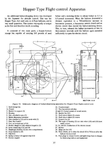
Hopper-Type Flight-control Apparatus<br />
An additional ballast-dropping device was developed<br />
by the Japanese for altitude control. This was the<br />
Hopper Type, but used only on A-Type balloons, and in<br />
very small quantities. This system was equally as unique<br />
as the first and therefore worth recording.<br />
It consisted of two main parts; a hopper-bottom<br />
storage bin capable of carrying 265 pounds of sand<br />
ballast and a metering devise to release ballast in 5.5 to<br />
6.5-pound increments. When the balloon descended a<br />
distance equivalent to a 700-millimeter increase in<br />
barometric pressure, a barometric switch closed and an<br />
electric circuit thus started the ballast-metering device.<br />
This, in turn, released the ballast increments at two to<br />
three-minute intervals until the balloon again ascended<br />
sufficiently to open the electric circuit.<br />
SECTION<br />
A-A<br />
Figure 74.<br />
Schematic diagram of ballast-dispensing apparatus for Hopper-Type flight-control unit.<br />
1. Sand storage bin<br />
la. Funnel<br />
2. Bracket to support (3)<br />
3. Housing<br />
4. Disc, attached to gear (7)<br />
5. Ballast dispensing container<br />
6. Gear attached to (5) and in mesh with (7)<br />
7. Gear. See 4 and 6<br />
8. Cam, an integral part of (6)<br />
9. Rocker, hinged at (30) which is hinged to (3)<br />
10. Lever connecting (13) and (9)<br />
11. Diaphragm dividing (5) into two compartments<br />
12. Stop attached to (4)<br />
13. Trip lever<br />
14. Spring to keep (13) against stop (12)<br />
15. Electric magnet<br />
57<br />
16. Counterweight<br />
17. Two barometric switches<br />
18 and 19. Contact points of circuit switch<br />
20. Bracket for (21)<br />
21. Shaft about which (3) rotates<br />
22. Shaft about which (5) rotates<br />
23. Support for (2)<br />
24. The angle of housing (3) can take when (18) and (19) have<br />
made contact<br />
25,26, and 28. Conductors of the electric circuit<br />
27. Battery<br />
29. Hinge pin for (13)<br />
30. Time switch, set to close the circuit 60 to 70 hours after the<br />
balloon was launched<br />
31. Fuse plugs to release bombs and ignite long fuses to charges<br />
for destroying balloon and equipment