3D Methodology for OBC Pre-Processing - CGGVeritas
3D Methodology for OBC Pre-Processing - CGGVeritas
3D Methodology for OBC Pre-Processing - CGGVeritas

You also want an ePaper? Increase the reach of your titles
YUMPU automatically turns print PDFs into web optimized ePapers that Google loves.
B044<br />
<strong>3D</strong> <strong>Methodology</strong> <strong>for</strong> <strong>OBC</strong><br />
<strong>Pre</strong>-<strong>Processing</strong><br />
M.T.A. Soudani* (TOTAL), J.L. Boelle (TOTAL), P. Hugonnet (CGG) &<br />
(University of Milan)<br />
SUMMARY<br />
It is more and more observed that <strong>OBC</strong> PZ images show better quali<br />
streamer. This is due to better multiple attenuation, multi-azim<br />
coverage. This leads to a wider bandwidth and a better signal to<br />
while <strong>3D</strong> <strong>OBC</strong> designs are considered as multi-2D acquisitions, the<br />
remain far from the ideals. In the following paper, a fully <strong>3D</strong> <strong>OBC</strong><br />
methodology is presented. This methodology is based on the <strong>3D</strong>(τ,p)<br />
the fact that a spatial trans<strong>for</strong>m is used, aliasing becomes a rea<br />
interpolation solution to overcome such a problem is briefly descri<br />
generalization of the PZ summation to <strong>3D</strong> is discussed and compared<br />
1D approach. Finally, a method <strong>for</strong> linear noise attenuation is des<br />
application on a real dataset shown.<br />
EAGE 68 th Conference & Exhibition — Vienna, Austria, 12 - 15 June 2006
Introduction:<br />
<strong>OBC</strong> technology allows the recording of multi-azimuth data thanks to a <strong>3D</strong> shot and receiver<br />
grid. Generally, the receiver gather domain is well-suited <strong>for</strong> <strong>OBC</strong> pre-processing. This is<br />
mainly due to the inconsistency from one receiver to another in terms of vector fidelity,<br />
coupling and noise coherency. In <strong>3D</strong> acquisitions, each receiver is related to a set of shots.<br />
This set can be polarized along one direction or regularly sampled in the inline and crossline<br />
directions. In the second case, it is possible to apply <strong>3D</strong> trans<strong>for</strong>ms such as (f,kx,ky) or the<br />
<strong>3D</strong>(τ,p) trans<strong>for</strong>m as far as the Shannon sampling condition is respected. The standard preprocessing<br />
algorithms are generally 2D and are applied sail-line by sail-line. Thus, the<br />
influence of the crossline offset is neglected. This may lead to errors especially on multiple<br />
attenuation algorithms. The use of <strong>3D</strong> trans<strong>for</strong>ms allows processing with respect to the three<br />
dimensions (t,x,y) or (t,r,ψ) where r is the offset and ψ the azimuth.<br />
The data shown in this paper are a <strong>3D</strong> receiver gather from a wide-azimuth survey acquired<br />
with a regular shot grid of (50m x 50m). In the following paragraphs, we will describe the<br />
main steps of a <strong>3D</strong> pre-processing methodology applied on this gather.<br />
Interpolation:<br />
According to Shannon’s sampling<br />
theory, and in the case of marine data,<br />
the spatial grid of (50m x 50m) leads to<br />
an aliasing frequency of 15Hz. Thus, it<br />
is necessary to interpolate the shots in<br />
order to have a finer grid and to shift the<br />
aliasing frequency outside the<br />
bandwidth of interest. Several<br />
interpolation algorithms have been<br />
tested. Although the problem is <strong>3D</strong>, the<br />
best results were provided by the 2D<br />
Spitz’ algorithm (Spitz 1991) applied in<br />
a <strong>3D</strong> context.<br />
Figure 1: Time slice calculated on a <strong>3D</strong> receiver<br />
gather (a) Be<strong>for</strong>e interpolation (b) After<br />
interpolation.<br />
<strong>Pre</strong>diction filters are calculated in the (f,x) and (f,y) domains in order to insert new shots in the<br />
inline and crossline directions respectively. After interpolation, the shot grid becomes (12.5m<br />
x 12.5m). However, after this step, the direct arrival is still aliased due to its low velocity and<br />
its high frequency components and is hence muted <strong>for</strong> further processing.<br />
Figure 1 shows a time slice calculated on the receiver gather at 2s. We see that the<br />
interpolation provides good results in terms of event kinematics and amplitude.<br />
<strong>3D</strong> (τ,p) trans<strong>for</strong>m:<br />
The <strong>3D</strong> linear (τ,p) trans<strong>for</strong>m is the <strong>3D</strong> extension of the well-known 2D slant stack. It is a<br />
plane wave decomposition of the <strong>3D</strong> seismic data. This decomposition is obtained by<br />
summing the data along axes defined in <strong>3D</strong> by the intercept τ and the two slopes px and py.<br />
Thus, the data is trans<strong>for</strong>med from the (t,x,y) domain to the (τ, px ,py) thanks to the equation:<br />
+∞ +∞<br />
( , p , p ) f ( τ − x.<br />
p − y.<br />
p , x,<br />
y)<br />
u y<br />
−∞<br />
−∞<br />
τ x y = ∫ ∫<br />
x<br />
dxdy<br />
(1)<br />
The trans<strong>for</strong>mation can also be seen in the cylindrical coordinates (τ, pr ,ψ) where ψ is the<br />
azimuth and pr is the radial slope:<br />
px<br />
= pr<br />
cos(<br />
ψ )<br />
(2)<br />
p = p sin ψ<br />
y<br />
r<br />
( )
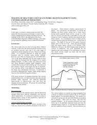
In the case of 2D propagation in a 1D horizontally stratified medium, the gathers recorded are<br />
composed of hyperbolae and trans<strong>for</strong>med to ellipses thanks to the 2D(τ, p) trans<strong>for</strong>m. In our<br />
<strong>3D</strong> case, each reflection on a layer generates a hyperboloid of revolution which is trans<strong>for</strong>med<br />
to an ellipsoid thanks to the <strong>3D</strong> slant stack.<br />
Two of the most important properties of the linear Radon trans<strong>for</strong>m concern the periodicity of<br />
the multiples and the velocity separation. Indeed, the linear Radon trans<strong>for</strong>m is a plane wave<br />
decomposition. For each trace in the <strong>3D</strong> slant stack domain, the periodicity is preserved,<br />
especially <strong>for</strong> water layer multiples. This period can be estimated from the water depth H, the<br />
water velocity Vw and the radial slope pr so that:<br />
T<br />
taup<br />
H<br />
( ) r p<br />
2<br />
pr 1−V<br />
w<br />
V w<br />
2<br />
= (3)<br />
On the other hand, linear events with low velocities are confined in the high values of p.<br />
In the next two paragraphs, we will show how we took advantage of these two properties <strong>for</strong><br />
water-layer multiple attenuation and linear low-velocity noise removal.<br />
<strong>3D</strong> PZ summation:<br />
Soubaras (1996) developed a 1D three step method to suppress water-layer multiples in <strong>OBC</strong><br />
data. This method does not require any a priori knowledge of seafloor parameters. Firstly, the<br />
vertical geophone is calibrated with a frequency dependent operator by taking the hydrophone<br />
as a reference. Then, the summation of the hydrophone and the calibrated geophone is<br />
per<strong>for</strong>med in order to separate the upgoing and downgoing wavefields, allowing ghost<br />
multiple attenuation. Finally, a reflectivity operator is estimated from the data in order to<br />
attenuate remaining peg-leg multiples by per<strong>for</strong>ming an adaptive subtraction between upgoing<br />
and downgoing wavefields.<br />
This three step approach is very effective because it is a data-driven method. However, it<br />
assumes a 1D propagation introducing a bias on the amplitudes at far offsets and does not<br />
handle the coherent linear noise on the vertical geophone.<br />
To overcome these limitations, Soudani et al (2005) generalized the Soubaras method in 2D<br />
and developed a new methodology <strong>for</strong> PZ summation in the (τ,p) domain to take into account<br />
the 2D propagation aspects.<br />
The generalization of this methodology to <strong>3D</strong> is straight<strong>for</strong>ward thanks to equation (3). The<br />
new PZ summation version assumes a full <strong>3D</strong> propagation of the wavefield and attenuates the<br />
water layer multiples with respect to the offset and azimuth.<br />
However, the complexity of the algorithm becomes O(N 2 ) and we face here a huge amount of<br />
data <strong>for</strong> each receiver gather in the <strong>3D</strong>(τ,p) domain. It is no longer possible to compute the<br />
operators <strong>for</strong> each value of the pair (px,py) separately.<br />
One way to overcome this difficulty is to split the <strong>3D</strong>(τ,p) gathers into sub-cubes. Each subcube<br />
is defined by four traces that correspond to four reference operators. Then, operators<br />
within the sub-cube are expressed with respect to the four reference operators according to<br />
equation (4):<br />
op ( i , j ) ( i , j )<br />
( i , j )<br />
( i , j )<br />
( i , j )<br />
= α ref 1 + β ref 2 + γ ref 3 + λ ref 4 (4)<br />
where i,j are the coordinates of the trace within the sub-cube, α, β, γ and λ are weighting<br />
functions and ref1, ref2, ref3 and ref4 are the four reference operators. The complexity of the<br />
algorithm becomes O((N/M)*(N/L)) where M and L are the number of traces per sub-cube in<br />
each direction.
(a) (b) (c) (d)<br />
Figure 2: Crossline just above the receiver. (a) hydrophone, (b) vertical geophone, (c) PZ processed<br />
with the 1D approach, (d) PZ processed with the new <strong>3D</strong> approach.<br />
Figure 2 shows the initial hydrophone and vertical geophone both in the crossline direction<br />
after incoherent noise removal. The <strong>3D</strong> PZ summation shows better results with less<br />
remaining multiples in comparison with the classical 1D approach.<br />
<strong>3D</strong> linear noise attenuation:<br />
One of the most important issues in <strong>OBC</strong> processing is the linear noise that we observe on the<br />
receiver gather domain and which is no longer coherent in the shot domain. This linear noise<br />
generally affects the vertical geophone. Thus, due to the PZ combination, this noise is<br />
introduced in the PZ section after water layer multiple attenuation. This noise can be seen in<br />
<strong>3D</strong> as a cone with a move out of about 1600-1800m/s. When we observe the data generated<br />
from a sail-line just above the receiver, this noise appears linear. However, when we analyze<br />
the gather from a displaced sail-line, this noise starts to be hyperbolic. This noise can be<br />
modelled as the intersection between a cone and a vertical plane. Up to now, the standard<br />
processing methodologies were processing the gathers sail-line by sail-line ignoring the<br />
crossline offset.<br />
After <strong>3D</strong>(τ,p) trans<strong>for</strong>m, the linear events with low velocity are moved to the high values of pr<br />
. Thus, by applying a mute in the <strong>3D</strong>(τ,p) domain, we can get rid of this noise.<br />
Figure 3 shows a receiver gather be<strong>for</strong>e and after linear noise attenuation as well as the<br />
removed noise on a sail-line just above the receiver and on a displaced sail-line. These figures<br />
illustrate how the noise moves from linear to hyperbolic with respect to the crossline offset.<br />
Conclusions:<br />
We have shown in this paper the key points of a new fully <strong>3D</strong> pre-processing workflow <strong>for</strong><br />
<strong>OBC</strong> data. This work is motivated by the desire to take advantage of the azimuth dimension.<br />
We have shown that the <strong>3D</strong>(τ,p) domain is well suited <strong>for</strong> water layer multiple attenuation and<br />
linear noise removal. Our 2D approach of PZ summation that attenuates both source side and<br />
receiver side multiples has been successfully extended to <strong>3D</strong>. Finally, the linear noise has<br />
been removed from the receiver gather improving drastically the final result. More<br />
comparisons with standard processing methodologies will be shown during the presentation.<br />
Acknowledgments<br />
The authors thank TOTAL <strong>for</strong> permission to show this work.
PZ gather be<strong>for</strong>e noise attenuation<br />
(a)<br />
PZ gather be<strong>for</strong>e noise attenuation<br />
References:<br />
(d)<br />
Crossline offset=0m<br />
PZ gather after noise attenuation<br />
(b)<br />
Crossline offset=1700m<br />
PZ gather after noise attenuation<br />
(e)<br />
Attenuated noise (a)-(b)<br />
(c)<br />
Attenuated noise (d)-(e)<br />
Figure 3: Linear noise attenuation <strong>for</strong> two different crossline offsets (0m and 1700m)<br />
Barr, F. J. and Sanders, J. I., 1989, Attenuation of water-column reverberations using pressure<br />
and velocity detectors in a water-bottom cable, 59th Ann. Internat. Mtg: Soc. of Expl.<br />
Geophys.<br />
Spitz, S., 1991, Seismic trace interpolation in the F-X domain: GEOPHYSICS, Soc. of Expl.<br />
Geophys., 56, 785-794.<br />
Soubaras, R., 1996, Ocean bottom hydrophone and geophone processing, 66th Ann. Internat.<br />
Mtg: Soc. of Expl. Geophys.<br />
Soudani, M.T.A., Boelle, J.L. and Mars, J., 2005, New methodology <strong>for</strong> water-layer multiple<br />
attenuation, , 67 th Mtg.: Eur. Assn. Geosci. Eng.<br />
(f)