Ardweeny Manual - Solarbotics
Ardweeny Manual - Solarbotics
Ardweeny Manual - Solarbotics

You also want an ePaper? Increase the reach of your titles
YUMPU automatically turns print PDFs into web optimized ePapers that Google loves.
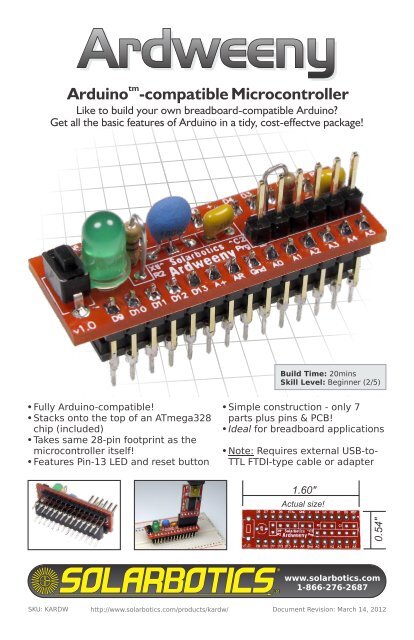
<strong>Ardweeny</strong><br />
tm<br />
Arduino -compatible Microcontroller<br />
Like to build your own breadboard-compatible Arduino?<br />
Get all the basic features of Arduino in a tidy, cost-effectve package!<br />
Build Time: 20mins<br />
Skill Level: Beginner (2/5)<br />
Fully Arduino-compatible!<br />
Stacks onto the top of an ATmega328<br />
chip (included)<br />
Takes same 28-pin footprint as the<br />
microcontroller itself!<br />
Features Pin-13 LED and reset button<br />
Simple construction - only 7<br />
parts plus pins & PCB!<br />
Ideal for breadboard applications<br />
Note: Requires external USB-to-<br />
TTL FTDI-type cable or adapter<br />
1.60"<br />
Actual size!<br />
0.54"<br />
www.solarbotics.com<br />
1-866-276-2687<br />
SKU: KARDW<br />
http://www.solarbotics.com/products/kardw/<br />
Document Revision: March 14, 2012
<strong>Ardweeny</strong> 1.0 Schematic<br />
VCC<br />
Prog<br />
6<br />
5<br />
4<br />
3<br />
2<br />
1<br />
C1 0.1µF<br />
Reset<br />
GND<br />
R1<br />
10K<br />
C2<br />
0.1µF<br />
1<br />
2<br />
3<br />
4<br />
5<br />
6<br />
7<br />
8<br />
9<br />
16Mhz<br />
Xtal<br />
10<br />
11<br />
12<br />
13<br />
14<br />
RST<br />
D0<br />
D1<br />
D2<br />
D3<br />
D4<br />
+<br />
GND<br />
XTAL<br />
XTAL<br />
D5<br />
D6<br />
D7<br />
D8<br />
A5<br />
A4<br />
A3<br />
A2<br />
A1<br />
A0<br />
GND<br />
AR<br />
A+<br />
D13<br />
D12<br />
D11<br />
D10<br />
D9<br />
28<br />
27<br />
26<br />
25<br />
24<br />
23<br />
22<br />
21<br />
20<br />
19<br />
18<br />
17<br />
16<br />
15<br />
GND<br />
R2<br />
470R<br />
LED1<br />
VCC<br />
ATMEGA8/168/328<br />
“Arduino” is a trademark of the Arduino Team (www.arduino.cc). The <strong>Ardweeny</strong><br />
is based off reference designs by the Arduino Team, and is licensed under the<br />
Creative Commons A-SA 2.5 license. Similarly, the <strong>Ardweeny</strong> is released under<br />
the same license. Get full design files from our website!<br />
http://creativecommons.org/licenses/by-sa/2.5/<br />
GND<br />
Disclaimer of Liability<br />
<strong>Solarbotics</strong> Ltd. is not responsible for any special, incidental, or consequential damages resulting<br />
from any breach of warranty, or under any legal theory, including lost profits, downtime, good-will,<br />
damage to or replacement of equipment or property, and any costs or recovering of any material or<br />
goods associated with the assembly or use of this product. <strong>Solarbotics</strong> Ltd. reserves the right to<br />
make substitutions and changes to this product without prior notice. Sorry - we hate legalese too,<br />
but “don’t pick on us” doesn’t impress the lawyers.<br />
www.solarbotics.com 2 <strong>Ardweeny</strong> <strong>Manual</strong> v1.3
Parts List<br />
1 x Printed Circuit Board (PCB)<br />
1 x ATmega328 with Arduino optiboot bootloader<br />
1 x LED (Pin 13 indicator)<br />
1 x 470 ohm resistors (Yellow / Purple / Brown)<br />
1 x SWT10 Switch (reset)<br />
2 x 0.1µF Ceramic Capacitors (power & auto-reset)<br />
1 x 10k resistor (Brown / Black / Orange) (auto-reset)<br />
1 x 16MHz resonator<br />
1 x 6-Pin male header (Programming / USB Pwr)<br />
2 x 14-Pin male headers (ATmega328 connectors)<br />
2 x 14-pin strips<br />
6-pin strip<br />
(programming)<br />
10k<br />
Resistor<br />
6-pin strip<br />
(programming)<br />
ATmega328<br />
with Arduino Bootloader<br />
470 ohm<br />
Resistor<br />
Pin13<br />
LED<br />
2 x 0.1µF<br />
Capacitors<br />
SWT10<br />
Reset Switch<br />
16MHz<br />
Resonator<br />
We strongly suggest you count the parts in your kit to make sure you<br />
have all the parts listed (c’mon - there’s barely a handful of parts, so<br />
count them!). If anything is missing, contact <strong>Solarbotics</strong> Ltd. for<br />
replacement parts information.<br />
www.solarbotics.com 3 <strong>Ardweeny</strong> <strong>Manual</strong> v1.3
Construction!<br />
You have a breadboard that needs an Arduino - Get to work! Never<br />
soldered before? Download a copy of our soldering tutorial here:<br />
http://downloads.solarbotics.com/pdf/solderingtutorial.pdf<br />
Step 1 - 0.1µF Capacitors: One is for power filtration, the other is part of the<br />
auto-reset function when a program is finished uploading. Stick one in<br />
position ‘C1’, and the other in position ‘C2’.<br />
Step 1:<br />
2 x 0.1µF Capacitors<br />
into ‘C1’ & ‘C2’<br />
Step 2 - 10k Resistor (Brown / Black / Orange): This one is part of the autoreset<br />
function too. Bend it over as shown, and install it to position ‘R1’.<br />
Step 3 - 470 ohm Resistor (Yellow / Purple / Brown): This is the currentlimiting<br />
resistor for the Pin-13 LED. Bend it like the other resistor, and<br />
install it to position ‘R2’.<br />
Step 2:<br />
10k resistor goes into<br />
position ‘R1’<br />
Step 3:<br />
470 ohm resistor goes<br />
into position ‘R2’<br />
www.solarbotics.com 4 <strong>Ardweeny</strong> <strong>Manual</strong> v1.3
Construction!<br />
Step 4: Install<br />
16MHz Resonator<br />
to position ‘Xtl’<br />
Step 4 - 16MHz Resonator: This<br />
gets installed in position ‘Xtl’. It<br />
doesn’t matter which-wayaround<br />
it goes in.<br />
Step 5: Install<br />
LED to position<br />
‘LED’ (watch<br />
orientation!)<br />
Step 5 - LED: It’s an Arduinoclone.<br />
It has to have a pin-13<br />
LED installed onboard! Unlike<br />
the resonator, make sure you<br />
have the shorter lead in the<br />
square pad (or just make<br />
sure the LED matches the<br />
outline on the PCB).<br />
Step 6 - Reset Switch: Stick it into the PCB, and solder it in!<br />
Step 7 - 6-Pin Programming Header: Jam the 6-pin header into position<br />
“Prg”. This is where you will plug in your USB / Serial converter.<br />
Step 6: Install<br />
the Reset Switch<br />
Step 7: Install the 6-pin programming<br />
header in position ‘Prg’<br />
Step 8 - 14-Pin Mounting Rails: Now<br />
we are getting close to completion!<br />
Mount the 14-pin headers on the<br />
underside of the board.<br />
Step 8:<br />
Mount each<br />
14-pin strip<br />
from the<br />
underside<br />
of the PCB<br />
www.solarbotics.com 5 <strong>Ardweeny</strong> <strong>Manual</strong> v1.3
Construction!<br />
Step 9 - Installing the microcontroller: Now we are getting to the best part -<br />
installing the microcontroller! The important part is to get it in the right-way<br />
around. Note the little curve printed on the PCB, and make sure it matches<br />
the notch on the microcontroller.<br />
Slide the microcontroller in between the<br />
legs so it grips the wide-portion of the legs.<br />
When you are happy with the fit, lightly<br />
solder the pins in place. Not too much<br />
solder! You do not want solder to slide down<br />
to the microcontroller pin tips.<br />
Step 9a: Important!<br />
Note the curve<br />
on the PCB matches<br />
the notch on the<br />
microcontroller<br />
Step 9b: Push the<br />
microcontroller in<br />
between the pins,<br />
just to the wide<br />
part<br />
Step 9c: Tack solder<br />
the PCB pins down,<br />
just to the top of the pin<br />
www.solarbotics.com 6 <strong>Ardweeny</strong> <strong>Manual</strong> v1.3
Using It!<br />
What’s great about the <strong>Ardweeny</strong> is that it takes up<br />
the same footprint as a microcontroller by<br />
itself. You simply plug it into your<br />
breadboard or PCB, and jack in<br />
your programming header.<br />
Set the Board in your<br />
Arduino IDE as the<br />
“Arduino Uno”, and treat it<br />
like any other Arduino!<br />
The pin-out matches the FTDI<br />
breakout cable standard, or the<br />
SparkFun FTDI Basic Breakout<br />
adapter (our part 50510). The<br />
plug’s GND line (also marked<br />
“BLK”) matches the <strong>Ardweeny</strong> pin<br />
marked with the “-”.<br />
Note the plug<br />
orientation:<br />
Gnd/Blk matches<br />
the ‘-’ symbol<br />
The FTDI adapter can power the<br />
<strong>Ardweeny</strong> and the other circuitry on the<br />
breadboard, if you connect the ‘GND’<br />
and ‘+’ pins to the rest of the<br />
breadboard power rails.<br />
www.solarbotics.com 7 <strong>Ardweeny</strong> <strong>Manual</strong> v1.3
The <strong>Solarbotics</strong> <strong>Ardweeny</strong>:<br />
The smallest Arduino-compatible Kit!<br />
We love Arduino. Those Italians know how to design an excellent<br />
microcontroller platform and share it with the world. And Mr. Kimio<br />
Kosaka’s “One-Chip-Arduino” project inspired us to develop the <strong>Ardweeny</strong>;<br />
the smallest Arduino you can build yourself with through-hole<br />
components!<br />
We’ve designed a backpack printed-circuit board the fits on top of an<br />
Atmel ATmega328 (it’d fit on a ‘168 too), straddling it. Solder the pins to<br />
the microcontroller’s legs, and you’re ready to join the open-source<br />
hardware revolution!<br />
Installed on breadboard,<br />
connected to programming<br />
adapter powered up and<br />
blinking happily!<br />
Visit us online for more info and cool stuff:<br />
www.solarbotics.com<br />
<strong>Solarbotics</strong> Ltd.<br />
3740D - 11A Street NE, Suite 101<br />
Calgary, Alberta T2E 6M6<br />
Canada<br />
Toll Free: 1-866-276-2687<br />
International: +1 (403) 232-6268<br />
Fax: +1 (403) 226-3741<br />
Made in Canada