Design Guide - Solvay Plastics
Design Guide - Solvay Plastics
Design Guide - Solvay Plastics

Create successful ePaper yourself
Turn your PDF publications into a flip-book with our unique Google optimized e-Paper software.
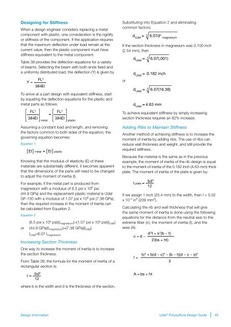
<strong>Design</strong>ing for Stiffness<br />
When a design engineer considers replacing a metal<br />
component with plastic, one consideration is the rigidity<br />
or stiffness of the component. If the application requires<br />
that the maximum deflection under load remain at the<br />
current value, then the plastic component must have<br />
stiffness equivalent to the metal component.<br />
Table 38 provides the deflection equations for a variety<br />
of beams. Selecting the beam with both ends fixed and<br />
a uniformly distributed load, the deflection (Y) is given by<br />
Y =<br />
FL 3<br />
384EI<br />
To arrive at a part design with equivalent stiffness, start<br />
by equating the deflection equations for the plastic and<br />
metal parts as follows:<br />
FL 3<br />
384EI<br />
metal<br />
=<br />
FL 3<br />
384EI<br />
plastic<br />
Assuming a constant load and length, and removing<br />
the factors common to both sides of the equation, the<br />
governing equation becomes:<br />
Equation 1<br />
[EI] metal = [EI] plastic<br />
Knowing that the modulus of elasticity (E) of these<br />
materials are substantially different, it becomes apparent<br />
that the dimensions of the parts will need to be changed<br />
to adjust the moment of inertia (I).<br />
For example, if the metal part is produced from<br />
magnesium with a modulus of 6.5 psi x 10 6 psi<br />
(44.9 GPa) and the replacement plastic material is Udel<br />
GF-130 with a modulus of 1.07 psi x 10 6 psi (7.38 GPa),<br />
then the required increase in the moment of inertia can<br />
be calculated from Equation 2.<br />
Equation 2<br />
(6.5 psi x 10 6 psi)(I magnesium )=(1.07 psi x 10 6 psi)(I Udel )<br />
or (44.9 GPa)(I magnesium )=(7.38 GPa)(I Udel )<br />
I Udel =6.07 I magnesium<br />
Increasing Section Thickness<br />
One way to increase the moment of inertia is to increase<br />
the section thickness.<br />
From Table 39, the formula for the moment of inertia of a<br />
rectangular section is:<br />
Substituting into Equation 2 and eliminating<br />
common factors:<br />
If the section thickness in magnesium was 0.100 inch<br />
(2.54 mm), then<br />
3<br />
d<br />
Udel<br />
= 6.07(.001)<br />
or<br />
d<br />
3<br />
6.07d 3<br />
Udel<br />
d<br />
Udel<br />
=<br />
magnesium<br />
3<br />
d<br />
Udel<br />
= 6.07(16.38)<br />
d<br />
Udel<br />
To achieve equivalent stiffness by simply increasing<br />
section thickness requires an 82% increase.<br />
Adding Ribs to Maintain Stiffness<br />
Another method of achieving stiffness is to increase the<br />
moment of inertia by adding ribs. The use of ribs can<br />
reduce wall thickness and weight, and still provide the<br />
required stiffness.<br />
Because the material is the same as in the previous<br />
example, the moment of inertia of the rib design is equal<br />
to the moment of inertia of the 0.182 inch (4.63 mm)-thick<br />
plate. The moment of inertia of the plate is given by:<br />
I plate<br />
=<br />
=<br />
0.182 inch<br />
4.63 mm<br />
bd 3<br />
12<br />
If we assign 1 inch (25.4 mm) to the width, then I = 5.02<br />
x 10 -4 in 4 (209 mm 4 ).<br />
Calculating the rib and wall thickness that will give<br />
the same moment of inertia is done using the following<br />
equations for the distance from the neutral axis to the<br />
extreme fiber (c), the moment of inertia (I), and the<br />
area (A).<br />
d 2 t + s 2 (b − t)<br />
c = d −<br />
2(bs + ht)<br />
I =<br />
=<br />
tc 3 + b(d − c) 3 − (b − t)(d − c − s) 3<br />
3<br />
I =<br />
bd 3<br />
12<br />
A = bs + ht<br />
where b is the width and d is the thickness of the section.<br />
<strong>Design</strong> Information<br />
Udel ® Polysulfone <strong>Design</strong> <strong>Guide</strong><br />
45