Acer Aspire 4252/4552/4552G_SG
Acer Aspire 4252/4552/4552G_SG
Acer Aspire 4252/4552/4552G_SG

Create successful ePaper yourself
Turn your PDF publications into a flip-book with our unique Google optimized e-Paper software.
<strong>Acer</strong> <strong>Aspire</strong> <strong>4252</strong>/<strong>4552</strong>/<strong>4552</strong>G<br />
Service Guide<br />
Service guide files and updates are available<br />
on the ACER/CSD web; for more information,<br />
please refer to http://csd.acer.com.tw<br />
PRINTED IN TAIWAN
Revision History<br />
Please refer to the table below for the updates made on this service guides.<br />
Date Chapter Updates<br />
II
Copyright<br />
Copyright © 2010 by <strong>Acer</strong> Incorporated. All rights reserved. No part of this publication may be reproduced,<br />
transmitted, transcribed, stored in a retrieval system, or translated into any language or computer language, in<br />
any form or by any means, electronic, mechanical, magnetic, optical, chemical, manual or otherwise, without<br />
the prior written permission of <strong>Acer</strong> Incorporated.<br />
Disclaimer<br />
The information in this guide is subject to change without notice.<br />
<strong>Acer</strong> Incorporated makes no representations or warranties, either expressed or implied, with respect to the<br />
contents hereof and specifically disclaims any warranties of merchantability or fitness for any particular<br />
purpose. Any <strong>Acer</strong> Incorporated software described in this manual is sold or licensed "as is". Should the<br />
programs prove defective following their purchase, the buyer (and not <strong>Acer</strong> Incorporated, its distributor, or its<br />
dealer) assumes the entire cost of all necessary servicing, repair, and any incidental or consequential<br />
damages resulting from any defect in the software.<br />
<strong>Acer</strong> is a registered trademark of <strong>Acer</strong> Corporation.<br />
Intel is a registered trademark of Intel Corporation.<br />
Other brand and product names are trademarks and/or registered trademarks of their respective holders.<br />
III
Conventions<br />
The following conventions are used in this manual:<br />
SCREEN MESSAGES<br />
NOTE<br />
WARNING<br />
CAUTION<br />
IMPORTANT<br />
Denotes actual messages that appear<br />
on screen.<br />
Gives bits and pieces of additional<br />
information related to the current<br />
topic.<br />
Alerts you to any damage that might<br />
result from doing or not doing specific<br />
actions.<br />
Gives precautionary measures to<br />
avoid possible hardware or software<br />
problems.<br />
Reminds you to do specific actions<br />
relevant to the accomplishment of<br />
procedures.<br />
NOTE: This symbol where placed in the Service Guide designates a component that should<br />
be recycled according to the local regulations.<br />
IV
Preface<br />
Before using this information and the product it supports, please read the following general information.<br />
1. This Service Guide provides you with all technical information relating to the BASIC CONFIGURATION<br />
decided for <strong>Acer</strong>'s "global" product offering. To better fit local market requirements and enhance product<br />
competitiveness, your regional office MAY have decided to extend the functionality of a machine (e.g.<br />
add-on card, modem, or extra memory capability). These LOCALIZED FEATURES will NOT be covered<br />
in this generic service guide. In such cases, please contact your regional offices or the responsible<br />
personnel/channel to provide you with further technical details.<br />
2. Please note WHEN ORDERING FRU PARTS, that you should check the most up-to-date information<br />
available on your regional web or channel. If, for whatever reason, a part number change is made, it will<br />
not be noted in the printed Service Guide. For ACER-AUTHORIZED SERVICE PROVIDERS, your <strong>Acer</strong><br />
office may have a DIFFERENT part number code to those given in the FRU list of this printed Service<br />
Guide. You MUST use the list provided by your regional <strong>Acer</strong> office to order FRU parts for repair and<br />
service of customer machines.<br />
V
Table of Contents<br />
System Specifications 1<br />
Features . . . . . . . . . . . . . . . . . . . . . . . . . . . . . . . . . . . . . . . . . . . . . . . . . . . . . . . . . . . .1<br />
System Block Diagram . . . . . . . . . . . . . . . . . . . . . . . . . . . . . . . . . . . . . . . . . . . . . . . . .6<br />
Your <strong>Acer</strong> Notebook tour . . . . . . . . . . . . . . . . . . . . . . . . . . . . . . . . . . . . . . . . . . . . . . .7<br />
Top View . . . . . . . . . . . . . . . . . . . . . . . . . . . . . . . . . . . . . . . . . . . . . . . . . . . . . . . .7<br />
Closed Front View . . . . . . . . . . . . . . . . . . . . . . . . . . . . . . . . . . . . . . . . . . . . . . . . .8<br />
Rear view . . . . . . . . . . . . . . . . . . . . . . . . . . . . . . . . . . . . . . . . . . . . . . . . . . . . . . .9<br />
Left View . . . . . . . . . . . . . . . . . . . . . . . . . . . . . . . . . . . . . . . . . . . . . . . . . . . . . . . .9<br />
Right View . . . . . . . . . . . . . . . . . . . . . . . . . . . . . . . . . . . . . . . . . . . . . . . . . . . . . .10<br />
Base View . . . . . . . . . . . . . . . . . . . . . . . . . . . . . . . . . . . . . . . . . . . . . . . . . . . . . .10<br />
Indicators . . . . . . . . . . . . . . . . . . . . . . . . . . . . . . . . . . . . . . . . . . . . . . . . . . . . . .11<br />
Touchpad Basics . . . . . . . . . . . . . . . . . . . . . . . . . . . . . . . . . . . . . . . . . . . . . . . .12<br />
Using the Keyboard . . . . . . . . . . . . . . . . . . . . . . . . . . . . . . . . . . . . . . . . . . . . . . . . . .13<br />
Lock Keys and embedded numeric keypad . . . . . . . . . . . . . . . . . . . . . . . . . . . .13<br />
Windows Keys . . . . . . . . . . . . . . . . . . . . . . . . . . . . . . . . . . . . . . . . . . . . . . . . . .14<br />
Hot Keys . . . . . . . . . . . . . . . . . . . . . . . . . . . . . . . . . . . . . . . . . . . . . . . . . . . . . . .15<br />
Hardware Specifications and Configurations . . . . . . . . . . . . . . . . . . . . . . . . . . . . . . .16<br />
System Utilities 31<br />
BIOS Setup Utility . . . . . . . . . . . . . . . . . . . . . . . . . . . . . . . . . . . . . . . . . . . . . . . . . . . .31<br />
Navigating the BIOS Utility . . . . . . . . . . . . . . . . . . . . . . . . . . . . . . . . . . . . . . . . .31<br />
Information . . . . . . . . . . . . . . . . . . . . . . . . . . . . . . . . . . . . . . . . . . . . . . . . . . . . .32<br />
Main . . . . . . . . . . . . . . . . . . . . . . . . . . . . . . . . . . . . . . . . . . . . . . . . . . . . . . . . . .33<br />
Security . . . . . . . . . . . . . . . . . . . . . . . . . . . . . . . . . . . . . . . . . . . . . . . . . . . . . . . .34<br />
Boot . . . . . . . . . . . . . . . . . . . . . . . . . . . . . . . . . . . . . . . . . . . . . . . . . . . . . . . . . . .37<br />
Exit . . . . . . . . . . . . . . . . . . . . . . . . . . . . . . . . . . . . . . . . . . . . . . . . . . . . . . . . . . .38<br />
BIOS Flash Utility . . . . . . . . . . . . . . . . . . . . . . . . . . . . . . . . . . . . . . . . . . . . . . . . . . . .39<br />
BIOS Flash Utility . . . . . . . . . . . . . . . . . . . . . . . . . . . . . . . . . . . . . . . . . . . . . . . . . . . .40<br />
DOS Flash Utility . . . . . . . . . . . . . . . . . . . . . . . . . . . . . . . . . . . . . . . . . . . . . . . . .40<br />
WinFlash Utility . . . . . . . . . . . . . . . . . . . . . . . . . . . . . . . . . . . . . . . . . . . . . . . . . .40<br />
Remove HDD/BIOS Password Utilities . . . . . . . . . . . . . . . . . . . . . . . . . . . . . . . . . . . .41<br />
Removing BIOS Passwords: . . . . . . . . . . . . . . . . . . . . . . . . . . . . . . . . . . . . . . . .42<br />
Cleaning BIOS Passwords . . . . . . . . . . . . . . . . . . . . . . . . . . . . . . . . . . . . . . . . .43<br />
Miscellaneous Utilities . . . . . . . . . . . . . . . . . . . . . . . . . . . . . . . . . . . . . . . . . . . . .44<br />
Machine Disassembly and Replacement 47<br />
Disassembly Requirements . . . . . . . . . . . . . . . . . . . . . . . . . . . . . . . . . . . . . . . . . . . .47<br />
Pre-disassembly Instructions . . . . . . . . . . . . . . . . . . . . . . . . . . . . . . . . . . . . . . .48<br />
Disassembly Process . . . . . . . . . . . . . . . . . . . . . . . . . . . . . . . . . . . . . . . . . . . . .49<br />
External Modules Disassembly Process . . . . . . . . . . . . . . . . . . . . . . . . . . . . . . . . . . .50<br />
External Modules Disassembly Flowchart . . . . . . . . . . . . . . . . . . . . . . . . . . . . .50<br />
Removing the Battery Pack . . . . . . . . . . . . . . . . . . . . . . . . . . . . . . . . . . . . . . . .51<br />
Removing the SD Dummy Card . . . . . . . . . . . . . . . . . . . . . . . . . . . . . . . . . . . . .52<br />
Removing the Keyboard . . . . . . . . . . . . . . . . . . . . . . . . . . . . . . . . . . . . . . . . . . .53<br />
Removing the ODD Module . . . . . . . . . . . . . . . . . . . . . . . . . . . . . . . . . . . . . . . .55<br />
Main Unit Disassembly Process . . . . . . . . . . . . . . . . . . . . . . . . . . . . . . . . . . . . . . . . .57<br />
Main Unit Disassembly Flowchart . . . . . . . . . . . . . . . . . . . . . . . . . . . . . . . . . . . .57<br />
Removing the Lower Cover . . . . . . . . . . . . . . . . . . . . . . . . . . . . . . . . . . . . . . . .58<br />
Component Overview . . . . . . . . . . . . . . . . . . . . . . . . . . . . . . . . . . . . . . . . . . . . .59<br />
Removing the DIMM Modules . . . . . . . . . . . . . . . . . . . . . . . . . . . . . . . . . . . . . . .60<br />
Removing the WLAN Module . . . . . . . . . . . . . . . . . . . . . . . . . . . . . . . . . . . . . . .61<br />
Removing the USB Board . . . . . . . . . . . . . . . . . . . . . . . . . . . . . . . . . . . . . . . . . .62<br />
Removing the RTC Battery . . . . . . . . . . . . . . . . . . . . . . . . . . . . . . . . . . . . . . . . .64<br />
VII
Table of Contents<br />
Removing the Bluetooth Module . . . . . . . . . . . . . . . . . . . . . . . . . . . . . . . . . . . . .65<br />
Removing the HDD Module . . . . . . . . . . . . . . . . . . . . . . . . . . . . . . . . . . . . . . . .66<br />
Removing the LCD Module . . . . . . . . . . . . . . . . . . . . . . . . . . . . . . . . . . . . . . . . .68<br />
Removing the Thermal Module . . . . . . . . . . . . . . . . . . . . . . . . . . . . . . . . . . . . . .70<br />
Removing the CPU . . . . . . . . . . . . . . . . . . . . . . . . . . . . . . . . . . . . . . . . . . . . . . .72<br />
Removing the Mainboard . . . . . . . . . . . . . . . . . . . . . . . . . . . . . . . . . . . . . . . . . .73<br />
LCD Module Disassembly Process . . . . . . . . . . . . . . . . . . . . . . . . . . . . . . . . . . . . . .75<br />
LCD Module Disassembly Flowchart . . . . . . . . . . . . . . . . . . . . . . . . . . . . . . . . .75<br />
Removing the LCD Bezel . . . . . . . . . . . . . . . . . . . . . . . . . . . . . . . . . . . . . . . . . .76<br />
Removing the Camera Module . . . . . . . . . . . . . . . . . . . . . . . . . . . . . . . . . . . . . .78<br />
Removing the LCD Panel . . . . . . . . . . . . . . . . . . . . . . . . . . . . . . . . . . . . . . . . . .79<br />
Remove the LCD Hinges . . . . . . . . . . . . . . . . . . . . . . . . . . . . . . . . . . . . . . . . . .80<br />
Removing the LVDS Cable . . . . . . . . . . . . . . . . . . . . . . . . . . . . . . . . . . . . . . . . .81<br />
Removing the WLAN Antennas . . . . . . . . . . . . . . . . . . . . . . . . . . . . . . . . . . . . .82<br />
LCD Module Assembly Process . . . . . . . . . . . . . . . . . . . . . . . . . . . . . . . . . . . . . . . . .83<br />
Replacing the WLAN Antennas . . . . . . . . . . . . . . . . . . . . . . . . . . . . . . . . . . . . .83<br />
Replacing the LVDS Cable . . . . . . . . . . . . . . . . . . . . . . . . . . . . . . . . . . . . . . . . .84<br />
Replacing the LCD Hinges . . . . . . . . . . . . . . . . . . . . . . . . . . . . . . . . . . . . . . . . .85<br />
Removing the LCD Panel . . . . . . . . . . . . . . . . . . . . . . . . . . . . . . . . . . . . . . . . . .86<br />
Replacing the Camera Module . . . . . . . . . . . . . . . . . . . . . . . . . . . . . . . . . . . . . .88<br />
Replacing the LCD Bezel . . . . . . . . . . . . . . . . . . . . . . . . . . . . . . . . . . . . . . . . . .89<br />
Main Unit Assembly Process . . . . . . . . . . . . . . . . . . . . . . . . . . . . . . . . . . . . . . . . . . .92<br />
Replacing the Mainboard . . . . . . . . . . . . . . . . . . . . . . . . . . . . . . . . . . . . . . . . . .92<br />
Replacing the CPU . . . . . . . . . . . . . . . . . . . . . . . . . . . . . . . . . . . . . . . . . . . . . . .94<br />
Replacing the Thermal Module . . . . . . . . . . . . . . . . . . . . . . . . . . . . . . . . . . . . . .95<br />
Replacing the LCD Module . . . . . . . . . . . . . . . . . . . . . . . . . . . . . . . . . . . . . . . . .97<br />
Replacing the Bluetooth Module . . . . . . . . . . . . . . . . . . . . . . . . . . . . . . . . . . . . .99<br />
Replacing the HDD Module . . . . . . . . . . . . . . . . . . . . . . . . . . . . . . . . . . . . . . .100<br />
Removing the RTC Battery . . . . . . . . . . . . . . . . . . . . . . . . . . . . . . . . . . . . . . . .103<br />
Replacing the USB Board . . . . . . . . . . . . . . . . . . . . . . . . . . . . . . . . . . . . . . . . .104<br />
Replacing the WLAN Module . . . . . . . . . . . . . . . . . . . . . . . . . . . . . . . . . . . . . .105<br />
Replacing the DIMM Modules . . . . . . . . . . . . . . . . . . . . . . . . . . . . . . . . . . . . . .107<br />
Replacing the Lower Cover . . . . . . . . . . . . . . . . . . . . . . . . . . . . . . . . . . . . . . . .108<br />
External Module Assembly Process . . . . . . . . . . . . . . . . . . . . . . . . . . . . . . . . . . . . .109<br />
Replacing the ODD Module . . . . . . . . . . . . . . . . . . . . . . . . . . . . . . . . . . . . . . .109<br />
Replacing the Keyboard . . . . . . . . . . . . . . . . . . . . . . . . . . . . . . . . . . . . . . . . . .110<br />
Replacing the SD dummy card . . . . . . . . . . . . . . . . . . . . . . . . . . . . . . . . . . . . .112<br />
Replacing the Battery Pack . . . . . . . . . . . . . . . . . . . . . . . . . . . . . . . . . . . . . . . .112<br />
Troubleshooting 113<br />
Common Problems . . . . . . . . . . . . . . . . . . . . . . . . . . . . . . . . . . . . . . . . . . . . . . . . . .113<br />
Power On Issue . . . . . . . . . . . . . . . . . . . . . . . . . . . . . . . . . . . . . . . . . . . . . . . .114<br />
No Display Issue . . . . . . . . . . . . . . . . . . . . . . . . . . . . . . . . . . . . . . . . . . . . . . . .115<br />
Random Loss of BIOS Settings . . . . . . . . . . . . . . . . . . . . . . . . . . . . . . . . . . . .116<br />
LCD Failure . . . . . . . . . . . . . . . . . . . . . . . . . . . . . . . . . . . . . . . . . . . . . . . . . . . .117<br />
Built-In Keyboard Failure . . . . . . . . . . . . . . . . . . . . . . . . . . . . . . . . . . . . . . . . .117<br />
Touchpad Failure . . . . . . . . . . . . . . . . . . . . . . . . . . . . . . . . . . . . . . . . . . . . . . .118<br />
Internal Speaker Failure . . . . . . . . . . . . . . . . . . . . . . . . . . . . . . . . . . . . . . . . . .118<br />
HDD Not Operating Correctly . . . . . . . . . . . . . . . . . . . . . . . . . . . . . . . . . . . . . .120<br />
ODD Failure . . . . . . . . . . . . . . . . . . . . . . . . . . . . . . . . . . . . . . . . . . . . . . . . . . .121<br />
Wireless Function Failure . . . . . . . . . . . . . . . . . . . . . . . . . . . . . . . . . . . . . . . . .124<br />
Thermal Unit Failure . . . . . . . . . . . . . . . . . . . . . . . . . . . . . . . . . . . . . . . . . . . . .124<br />
External Mouse Failure . . . . . . . . . . . . . . . . . . . . . . . . . . . . . . . . . . . . . . . . . . .125<br />
Other Failures . . . . . . . . . . . . . . . . . . . . . . . . . . . . . . . . . . . . . . . . . . . . . . . . . .125<br />
Intermittent Problems . . . . . . . . . . . . . . . . . . . . . . . . . . . . . . . . . . . . . . . . . . . . . . . .126<br />
VIII
Table of Contents<br />
Undetermined Problems . . . . . . . . . . . . . . . . . . . . . . . . . . . . . . . . . . . . . . . . . . . . . .126<br />
Post Codes . . . . . . . . . . . . . . . . . . . . . . . . . . . . . . . . . . . . . . . . . . . . . . . . . . . . . . . .127<br />
Jumper and Connector Locations 131<br />
Top View . . . . . . . . . . . . . . . . . . . . . . . . . . . . . . . . . . . . . . . . . . . . . . . . . . . . . .131<br />
Bottom View . . . . . . . . . . . . . . . . . . . . . . . . . . . . . . . . . . . . . . . . . . . . . . . . . . .132<br />
Clearing Password Check and BIOS Recovery . . . . . . . . . . . . . . . . . . . . . . . . . . . .133<br />
Clearing Password Check . . . . . . . . . . . . . . . . . . . . . . . . . . . . . . . . . . . . . . . . .133<br />
BIOS Recovery by Crisis Disk . . . . . . . . . . . . . . . . . . . . . . . . . . . . . . . . . . . . .134<br />
FRU (Field Replaceable Unit) List 135<br />
<strong>Acer</strong> <strong>Aspire</strong> <strong>4252</strong>/<strong>4552</strong>/<strong>4552</strong>G Exploded Diagrams . . . . . . . . . . . . . . . . . . . . . . . . .136<br />
LCD Assembly . . . . . . . . . . . . . . . . . . . . . . . . . . . . . . . . . . . . . . . . . . . . . . . . .136<br />
<strong>Acer</strong> <strong>Aspire</strong> <strong>4252</strong>/<strong>4552</strong>/<strong>4552</strong>G FRU List . . . . . . . . . . . . . . . . . . . . . . . . . . . . . .138<br />
Screw List . . . . . . . . . . . . . . . . . . . . . . . . . . . . . . . . . . . . . . . . . . . . . . . . . . . . .138<br />
Model Definition and Configuration 140<br />
<strong>Aspire</strong> <strong>4252</strong> . . . . . . . . . . . . . . . . . . . . . . . . . . . . . . . . . . . . . . . . . . . . . . . . . . . .140<br />
<strong>Aspire</strong> <strong>4552</strong> . . . . . . . . . . . . . . . . . . . . . . . . . . . . . . . . . . . . . . . . . . . . . . . . . . . .142<br />
<strong>Aspire</strong> <strong>4552</strong>G . . . . . . . . . . . . . . . . . . . . . . . . . . . . . . . . . . . . . . . . . . . . . . . . . .148<br />
Test Compatible Components 157<br />
Online Support Information 161<br />
Index 163<br />
IX
Table of Contents<br />
X
Chapter 1<br />
System Specifications<br />
Features<br />
Below is a brief summary of the computer’s many features:<br />
NOTE: Items denoted with an (*) are only available for selected models.<br />
Operating system<br />
• Genuine Windows® 7 Home Premium 64-bit<br />
• Genuine Windows® 7 Home Basic 64-bit<br />
CPU and chipset<br />
<strong>Aspire</strong> <strong>4552</strong> and <strong>4552</strong>G<br />
• AMD Phenom II quad-core mobile processor N950 (2 MB L2 cache, 2.10 GHz, DDR3 1333<br />
MHz, 35 W)<br />
• AMD Phenom II triple-core mobile processor N850 (1.5 MB L2 cache, 2.20 GHz, DDR3 1333<br />
MHz, 35 W)<br />
• AMD Phenom II dual-core mobile processor N620/N640 (2 MB L2 cache, 2.80/2.90 GHz, DDR3<br />
1333 MHz, 35 W)<br />
• AMD Turion II dual-core mobile processor P540 (2 MB L2 cache, 2.40 GHz, DDR3 1066 MHz,<br />
25 W)<br />
• AMD Athlon II dual-core processor P320/P340 (1 MB L2 cache, 2.10/2.20 GHz, DDR3 1066<br />
MHz, 25 W), N350 (1 MB L2 cache, 2.40 GHz, DDR3 1066 MHz, 35 W)<br />
• AMD M880G Chipset<br />
<strong>Aspire</strong> <strong>4252</strong><br />
• AMD V Series processor V140 (512 KB L2 cache, 2.30 GHz, DDR3 1066 MHz, 25 W)<br />
• AMD M880G Chipset<br />
System memory<br />
Display<br />
• Dual-channel DDR3 SDRAM support:<br />
• Up to 4 GB of DDR3 system memory, upgradable to 8 GB using two soDIMM modules<br />
• 14" HD 1366 x 768 pixel resolution, high-brightness (200-nit) <strong>Acer</strong> CineCrystal LED-backlit TFT<br />
LCD<br />
• Mercury free, environment friendly<br />
• 16:9 aspect ratio<br />
Chapter 1 1
Graphics<br />
<strong>Aspire</strong> <strong>4252</strong> and 2552<br />
• ATI Radeon HD 4250 Graphics with 256 MB of dedicated system memory, supporting Unified<br />
Video Decoder 2 (UVD2), OpenGL® 2.0, OpenEXR High Dynamic-Range (HDR) technology,<br />
Shader Model 4.1, Microsoft® DirectX® 10.1<br />
<strong>Aspire</strong> <strong>4552</strong>G<br />
• ATI Mobility Radeon HD 5470 with up to 3579 MB of HyperMemory (512 MB of dedicated<br />
DDR3 VRAM, up to 3067 MB of shared system memory), supporting Unified Video Decoder<br />
(UVD), OpenEXR High Dynamic-Range (HDR) technology, Shader Model 5.0, Microsoft ®<br />
DirectX ® 11, OpenGL ® 3.1, OpenCL 1.1<br />
• Dual independent display support<br />
• 16.7 million colors<br />
• External resolution / refresh rate:<br />
• VGA port up to 2048 x 1536: 85 Hz<br />
• HDMI port up to 1920 x 1080: 60 Hz<br />
• MPEG-2/DVD decoding<br />
• VC-1 and H.264 (AVC) decoding<br />
• HDMI (High-Definition Multimedia Interface) with HDCP (High-bandwidth Digital Content<br />
Protection) support<br />
Audio<br />
• Built-in speaker<br />
• High-definition audio support<br />
• Built-in microphone<br />
• MS-Sound compatible<br />
Storage<br />
• Hard disk drive<br />
• 160/250/320/500/640/750 GB or larger<br />
• Multi-in-1 card reader, supporting:<br />
• Secure Digital (SD) Card and MultiMediaCard (MMC)<br />
Webcam<br />
• <strong>Acer</strong> Video Conference, featuring:<br />
• <strong>Acer</strong> Crystal Eye 1.3 MP webcam, 1280 x 1024 resolution<br />
2 Chapter 1
Wireless and networking<br />
• WLAN:<br />
• <strong>Acer</strong> InviLink Nplify 802.11b/g/n Wi-Fi CERTIFIED<br />
• <strong>Acer</strong> InviLink 802.11b/g Wi-Fi CERTIFIED802.11b/g/n Wi-Fi CERTIFIED <br />
• Supporting <strong>Acer</strong> SignalUp wireless technology<br />
• WPAN:<br />
• Bluetooth® 3.0+HS<br />
• Bluetooth® 2.1+EDR<br />
• LAN: Gigabit Ethernet, Wake-on-LAN ready<br />
Privacy control<br />
• BIOS user, supervisor, HDD passwords<br />
• Kensington lock slot<br />
Dimensions and weight<br />
• Dimensions<br />
• 341 (W) x 264.5 (D) x 26.7/33.5 (H) mm (13.43 x 10.41 x 1.05/1.32 inches)<br />
• Weight<br />
• 2.5 kg (5.51 lbs.) with 6-cell battery pack<br />
Power adapter and battery<br />
• ACPI 3.0 CPU power management standard: supports Standby and Hibernation power-saving<br />
modes<br />
Power adapter<br />
<strong>Aspire</strong> <strong>4252</strong> and <strong>4552</strong><br />
• 3-pin 65 W AC adapter:·<br />
• ·108 (W) x 46 (D) x 29.5 (H) mm (4.25 x 1.81 x 1.16 inches)<br />
• ·225 g (0.49 lbs.) with 180 cm DC cable<br />
<strong>Aspire</strong> <strong>4552</strong>G<br />
• 3-pin 65 W AC adapter:·<br />
• 133 (W) x 59 (D) x 31 (H) mm (5.23 x 2.32 x 1.22 inches)<br />
• 390 g (0.86 lbs.) with 180 cm DC cable<br />
Battery<br />
• 48 Wh 4400 mAh 6-cell Li-ion standard battery pack<br />
• Battery life: 3 hours<br />
• ENERGY STAR®<br />
<strong>Aspire</strong> <strong>4552</strong>G Only<br />
• <strong>Acer</strong> QuicCharge technology:<br />
• 80% charge in 1 hour<br />
• 2-hour rapid charge system-off<br />
Chapter 1 3
Input and control<br />
• Keyboard<br />
• 86-/87-/91-key <strong>Acer</strong> FineTip keyboard with international language support<br />
• Touchpad<br />
I/O interface<br />
Software<br />
• Multi-gesture touchpad, supporting two-finger scroll, pinch, rotate, flip<br />
• Media keys<br />
• Media control keys (printed on keyboard): play/pause, stop, previous, next, volume up,<br />
volume down<br />
• 2-in-1 card reader (SD, MMC)<br />
• Three USB 2.0 ports<br />
• HDMI port with HDCP support<br />
• External display (VGA) port<br />
• Headphone/speaker/line-out jack<br />
• Microphone-in jack<br />
• Ethernet (RJ-45) port<br />
• DC-in jack for AC adapter<br />
• Productivity<br />
• <strong>Acer</strong> Backup Manager<br />
• <strong>Acer</strong> ePower Management<br />
• <strong>Acer</strong> eRecovery Management<br />
• Adobe ® Flash ® Player 10.1<br />
• Adobe ® Reader ® 9.1<br />
• eSobi <br />
• Microsoft ® Office 2010 preloaded (purchase a product key to activate)<br />
• Microsoft ® Office Starter 2010<br />
• Norton Online Backup<br />
• Security<br />
• McAfee ® Internet Security Suite Trial<br />
• MyWinLocker ®<br />
• Multimedia<br />
• Cyberlink ® PowerDVD <br />
• NTI Media Maker <br />
• Gaming<br />
• Oberon GameZone<br />
• WildTangent ®<br />
• Communication and ISP<br />
4 Chapter 1
• <strong>Acer</strong> Crystal Eye<br />
• Microsoft ® Silverlight <br />
• Skype <br />
• Windows Live Essentials — Wave 3.2 (Mail, Photo Gallery, Live Messenger, Movie Maker,<br />
Writer)<br />
• Web links and utilities<br />
• <strong>Acer</strong> Accessory Store<br />
• <strong>Acer</strong> Identity Card<br />
• <strong>Acer</strong> Registration<br />
• <strong>Acer</strong> Updater<br />
Optional Items<br />
Warranty<br />
Environment<br />
• eBay ® shortcut 2009<br />
• Netflix shortcut<br />
• 1/2/4 GB DDR3 soDIMM module<br />
• 6-cell Li-ion battery pack<br />
• 3-pin 90 W AC adapter<br />
• One-year International Travelers Warranty (ITW)<br />
• Temperature:<br />
• Operating: 41 °F to 95 °F (5 °C to 35 °C)<br />
• Non-operating: -4 °F to -149 °F (20 °C to 65 °C)<br />
• Humidity (non-condensing):<br />
• Operating: 20% to 80%<br />
• Non-operating: 20% to 80%<br />
NOTE: The specifications listed above are for reference only. The exact configuration of the PC depends on<br />
the model purchased.<br />
Chapter 1 5
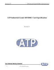
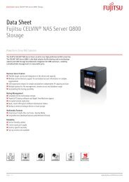
System Block Diagram<br />
25MHz<br />
LAN<br />
BROADCOM<br />
PCIE-LAN<br />
BCM57780<br />
(10/100/1000)<br />
RJ45<br />
DDR3- SODIMM1<br />
DDR3- SODIMM2<br />
P0<br />
Mini PCI-E<br />
Card<br />
(Wireless LAN)<br />
DDR3 channel A<br />
DDR3 channel B<br />
CPU SideBand TemperatureSense I2C<br />
HT3<br />
1.8GHz<br />
PCI-Expresss<br />
P2<br />
AMD Champlain<br />
S1G4 Processor<br />
35mm X 35mm<br />
638P (PGA) 35W<br />
NORTH BRIDGE<br />
RS880M GFX Engine: 500MHz<br />
A11<br />
21mm X 21mm, 528pin BGA<br />
TDP: 13W<br />
0.95 ~ 1.1V<br />
A-LINK<br />
CPU THERMAL<br />
SENSOR<br />
(Reserve Only)<br />
PCI-Express 16X<br />
CPU_CLK<br />
NBGFX_CLK<br />
NBGPP_CLK<br />
SBLINK_CLK<br />
PWM FAN SCH.<br />
ATI<br />
Park XT<br />
128-bit M2 Pkg<br />
29mm X 29mm<br />
VRAM DDR3<br />
64MX16X4,64 bit<br />
800MHz<br />
INT HDMI<br />
INT CRT<br />
INT LVDS<br />
EXT HDMI<br />
EXT CRT<br />
EXT LVDS<br />
CPU (PROCHOT)<br />
E.C. (CPUFAN#)<br />
HDMI<br />
CRT<br />
LVDS<br />
25MHz<br />
32.768KHz<br />
From SB<br />
CLK GEN<br />
SB820M<br />
CLK_PCI_775<br />
PCLK_DEBUG<br />
SATA - HDD<br />
SATA - ODD<br />
SATA0 150MB<br />
3 Gb/s<br />
SATA1 150MB<br />
3 Gb/s<br />
SOUTH BRIDGE<br />
SB820M<br />
A12<br />
23mm X 23mm, 605pin BGA<br />
P0<br />
USB2.0 Port<br />
on board x1<br />
P9<br />
Blue Tooth<br />
P13<br />
Web-Camera<br />
FFC<br />
USB BOARD<br />
No PCI I/F<br />
TDP: 4.9W<br />
PCLK_DEBUG<br />
P4<br />
Mini Card<br />
WLAN & Debug<br />
P10<br />
CardReader<br />
AU6347<br />
USB2.0 Ports x3<br />
LPC<br />
Azalia<br />
12MHz<br />
CLK_PCI_775<br />
CPU SideBand TemperatureSense I2C<br />
Winbond KBC<br />
NPCE781L<br />
Audio CODEC<br />
RTL ALC272X<br />
Keyboard<br />
TouchPad<br />
SPI ROM<br />
Digital MIC<br />
AUDIO CONN<br />
(H.P./ MIC)<br />
Speaker CN<br />
6 Chapter 1
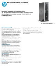
Your <strong>Acer</strong> Notebook tour<br />
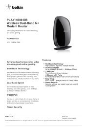
Top View<br />
1<br />
2<br />
3<br />
10<br />
4<br />
5<br />
6<br />
7<br />
9<br />
8<br />
# Icon Item Description<br />
1 <strong>Acer</strong> Crystal Eye<br />
webcam<br />
Web camera for video communication. (only for certain<br />
models)<br />
2 Display screen Also called Liquid-Crystal Display (LCD), displays computer<br />
output (configuration may vary by model).<br />
3 Power button Turns the computer on and off.<br />
4 Keyboard For entering data into your computer<br />
5 Touchpad Touch-sensitive pointing device which functions like a<br />
computer mouse.<br />
6 Click buttons<br />
(left, and right)<br />
The left and right buttons function like the left and right<br />
mouse buttons.<br />
7 Microphone Internal microphone for sound recording.<br />
Chapter 1 7
# Icon Item Description<br />
8 Power indicator Indicates the computer's power status.<br />
Battery indicator<br />
HDD indicator<br />
Indicates the computer's battery status.<br />
1. Charging: The light shows amber when the battery is<br />
charging.<br />
2. Fully charged: The light shows blue when in AC mode.<br />
Indicates when the hard disk drive is active.<br />
Communication<br />
indicator<br />
Indicates the computer’s wireless connectivity device status.<br />
9 Palmrest Comfortable support area for your hands when you use the<br />
computer.<br />
10 Speaker Delivers audio output.<br />
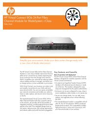
Closed Front View<br />
1 2<br />
No. Icon Item Description<br />
1 Microphone jack Accepts inputs from external microphones.<br />
Rear view<br />
Headphone/<br />
speaker/line-out<br />
jack<br />
Connects to audio line-out devices (e.g.,<br />
speakers, headphones).<br />
2 2-in-1 card reader Accepts Secure Digital (SD), MultiMediaCard<br />
(MMC).<br />
Note: Push to remove/install the card. Only one<br />
card can operate at any given time.<br />
No. Icon Item Description<br />
1 Battery bay Houses the computer's battery pack.<br />
1<br />
8 Chapter 1
Left View<br />
1 2 3 4 5 6 7<br />
No. Icon Item Description<br />
1 Kensington lock slot Connects to a Kensington-compatible computer<br />
security lock.<br />
Note: Wrap the computer security lock cable<br />
around an immovable object such as a table or<br />
handle of a locked drawer. Insert the lock into the<br />
notch and turn the key to secure the lock. Some<br />
keyless models are also available.<br />
2 DC-in jack Connects to an AC adapter.<br />
3 Ventilation slots Enable the computer to stay cool,<br />
even after prolonged use.<br />
4 External display<br />
(VGA) port<br />
Right View<br />
Connects to a display device (e.g., external<br />
monitor, LCD projector).<br />
5 Ethernet (RJ-45) port Connects to an Ethernet 10/100/1000-based<br />
network.<br />
6 HDMI port Supports high-definition digital video<br />
connections.<br />
7 USB 2.0 port Connects to USB 2.0 devices (e.g., USB mouse,<br />
USB camera).<br />
1 2 3 4 5<br />
No. Icon Item Description<br />
1 USB 2.0 ports Connect to USB 2.0 devices<br />
(e.g., USB mouse, USB camera).<br />
2 Optical drivez Internal optical drive; accepts CDs or<br />
DVDs.<br />
3 Optical disk access<br />
indicator<br />
4 Optical drive eject<br />
button<br />
Lights up when the optical drive is<br />
active.<br />
Ejects the optical disk from the drive .<br />
Chapter 1 9
5 Emergency eject<br />
hole<br />
Base View<br />
No. Icon Item Description<br />
Ejects the optical drive tray when the<br />
computer is turned off.<br />
Note: Insert a paper clip to the<br />
emergency eject hole to eject the<br />
optical drive tray when the computer<br />
is off.<br />
1<br />
2<br />
4<br />
3<br />
No. Icon Item Description<br />
1 Battery bay Houses the computer's battery pack.<br />
2 Battery lock Locks the battery in position.<br />
3 Ventilation slots Enable the computer to stay cool, even after<br />
prolonged use.<br />
4 Battery release<br />
latch<br />
Releases the battery for removal.<br />
10 Chapter 1
Indicators<br />
The computer has several easy-to-read status indicators.<br />
Icon Function Description<br />
Power<br />
Indicates the computer's power status.<br />
Battery<br />
HDD<br />
Indicates the computer's battery status.<br />
NOTE: 1. Charging: The light shows amber when<br />
the battery is charging. 2. Fully charged: The light<br />
shows green when in AC mode.<br />
Indicates when the hard disk drive is active.<br />
Communication indicator<br />
Indicates the computer’s wireless connectivity<br />
device status.<br />
Chapter 1 11
Touchpad Basics<br />
The following items show you how to use the Touchpad:<br />
• Move your finger across the Touchpad (1) to move the cursor.<br />
• Press the left (2) and right (3) buttons located beneath the Touchpad to perform selection and<br />
execution functions. These two buttons are similar to the left and right buttons on a mouse.<br />
Tapping on the Touchpad is the same as clicking the left button.<br />
Function Left Button (2) Right Button (3) Main Touchpad (1)<br />
Execute Quickly click twice. Tap twice (at the same speed<br />
as double-clicking a mouse<br />
button).<br />
Select Click once. Tap once.<br />
Drag<br />
Click and hold, then use<br />
finger on the Touchpad to<br />
drag the cursor.<br />
Tap twice (at the same speed<br />
as double-clicking a mouse<br />
button); rest your finger on<br />
the Touchpad on the second<br />
tap and drag the cursor.<br />
Access<br />
context menu<br />
Click once.<br />
NOTE: When using the Touchpad, keep it - and your fingers - dry and clean. The Touchpad is sensitive to<br />
finger movement; hence, the lighter the touch, the better the response. Tapping too hard will not<br />
increase the Touchpad’s responsiveness.<br />
12 Chapter 1
Using the Keyboard<br />
The keyboard has full-sized keys and an embedded numeric keypad, separate cursor, lock, Windows, function<br />
and special keys.<br />
Lock Keys and embedded numeric keypad<br />
The keyboard has two lock keys which you can toggle on and off.<br />
Lock key<br />
Caps Lock<br />
Num Lock<br />
+ <br />
Scroll Lock<br />
+ <br />
Description<br />
When Caps Lock is on, all alphabetic characters typed are in uppercase.<br />
When Num Lock is on, the embedded keypad is in numeric mode.<br />
When Scroll Lock is on, the screen moves one line up or down when you press<br />
the up or down arrow keys respectively. Scroll Lock does not work with some<br />
applications.<br />
Chapter 1 13
Windows Keys<br />
The keyboard has two keys that perform Windows-specific functions.<br />
Key<br />
Windows key<br />
Description<br />
Pressed alone, this key has the same effect as clicking on the Windows Start button;<br />
it launches the Start menu. It can also be used with other keys to provide a variety of<br />
functions:<br />
< >: Open or close the Start menu<br />
< > + : Display the desktop<br />
< > + : Open Windows Explore<br />
< > + : Search for a file or folder<br />
< > + : Cycle through Sidebar gadgets<br />
< > + : Lock your computer (if you are connected to a network domain), or<br />
switch users (if you're not connected to a network domain)<br />
< > + : Minimizes all windows<br />
< > + : Open the Run dialog box<br />
< > + : Cycle through programs on the taskbar<br />
< > + : Open Ease of Access Center<br />
< > + : Open Windows Mobility Center<br />
< > + : Display the System Properties dialog box<br />
< > + : Restore minimized windows to the desktop<br />
< > + : Cycle through programs on the taskbar<br />
< > + : Bring all gadgets to the front and select Windows Sidebar<br />
+ <<br />
> + : Search for computers (if you are on a network)<br />
+ < > + : Use the arrow keys to cycle through programs on the<br />
taskbar<br />
Note: Depending on your edition of Windows, some shortcuts may not function as<br />
described.<br />
14 Chapter 1
Hot Keys<br />
The computer employs hotkeys or key combinations to access most of the computer’s controls like screen<br />
brightness, volume output and the BIOS utility.<br />
To activate hot keys, press and hold the key before pressing the other key in the hotkey combination.<br />
Hotkey Icon Function Description<br />
+ Communication key Enables / disables the computer's<br />
communication devices. (Communication<br />
devices may vary by configuration.)<br />
+ Sleep Puts the computer in Sleep mode.<br />
+ Display toggle Switches display output between the display<br />
screen, external monitor (if connected) and<br />
both.<br />
+ Display Off Turns the display screen backlight off to save<br />
power. Press any key to return.<br />
+ Touchpad toggle Turns the internal Touchpad on and off.<br />
+ Speaker toggle Turns the speakers on and off.<br />
+ Brightness up Increases the screen brightness.<br />
+ Brightness down Decreases the screen brightness.<br />
+ Volume up Increases the sound volume.<br />
+ Volume down Decreases the sound volume.<br />
+ Play/Pause Play or pause a selected media file.<br />
+ Stop Stop playing the selected media file.<br />
+ Previous Return to the previous media file.<br />
+ Next Jump to the next media file.<br />
Chapter 1 15
Hardware Specifications and Configurations<br />
Processor<br />
Item<br />
Specification<br />
CPU<br />
AMD Family 10h Champlain Processor S1g4 Package<br />
Type<br />
35W CPU<br />
CPU Package 528-FCBGA package, 21mmx21mm - S1g3<br />
Power 1.1V<br />
On-die Cache 1MB L2 cache<br />
Front Side Bus 667/800/1066 MHz<br />
Processor Specifications (<strong>Aspire</strong> <strong>4552</strong>/5442G)<br />
Item<br />
CPU<br />
Speed<br />
(Ghz)<br />
Cores<br />
Bus<br />
Speed<br />
Mfg<br />
Tech<br />
Cache<br />
Size<br />
Package<br />
Core<br />
Voltage<br />
<strong>Acer</strong> P/N<br />
AAP320 2.1 2 3600<br />
MHz<br />
45 nm 1M 638-pin<br />
micro-<br />
PGA<br />
25W<br />
KC.AP002.320<br />
APN830 2.1 3 3600<br />
MHz<br />
45 nm 1.5M 638-pin<br />
micro-<br />
PGA<br />
35W<br />
KC.PN002.830<br />
APN930 2.0 4 3600<br />
MHz<br />
45 nm 2M 638-pin<br />
micro-<br />
PGA<br />
35W<br />
KC.PN002.930<br />
AAN350 2.4 2 3200<br />
MHz<br />
45 nm 1M 638-pin<br />
micro-<br />
PGA<br />
35W<br />
KC.AN002.350<br />
AAP340 2.2 2 3200<br />
MHz<br />
45 nm 1M 638-pin<br />
micro-<br />
PGA<br />
25W<br />
KC.AP002.340<br />
APN850 2.2 3 3600<br />
MHz<br />
45 nm 1.5M 638-pin<br />
micro-<br />
PGA<br />
35W<br />
KC.PN002.850<br />
APN950 2.1 4 3600<br />
MHz<br />
45 nm 2M 638-pin<br />
micro-<br />
PGA<br />
35W<br />
KC.PN002.950<br />
APP840 1.9 3 3600<br />
MHz<br />
45 nm 1.5M 638-pin<br />
micro-<br />
PGA<br />
25W<br />
KC.PP002.840<br />
APP940 1.7 4 3600<br />
MHz<br />
45 nm 2M 638-pin<br />
micro-<br />
PGA<br />
25W<br />
KC.PP002.940<br />
ATP540 2.4 2 3600<br />
MHz<br />
45 nm 2M 638-pin<br />
micro-<br />
PGA<br />
25W<br />
KC.TP002.540<br />
Processor Specifications (<strong>Aspire</strong> <strong>4252</strong>)<br />
Item<br />
CPU<br />
Speed<br />
(Ghz)<br />
Cores<br />
Bus<br />
Speed<br />
Mfg<br />
Tech<br />
Cache<br />
Size<br />
Package<br />
Core<br />
Voltage<br />
<strong>Acer</strong> P/N<br />
AMD<br />
V140<br />
2.3 1 3200<br />
MHz<br />
45 nm 512K 638-pin<br />
micro-<br />
PGA<br />
25W<br />
KC.V0002.140<br />
16 Chapter 1
North Bridge Chipset<br />
Item<br />
Specification<br />
Chipset<br />
RS880M<br />
Package • Single chip solution in 55nm, 1.1V low power CMOS technology.<br />
• 528-FCBGA package, 21mmx21mm.<br />
Features • CPU HyperTransport Interface<br />
• Caspian-series processors.<br />
• ATI HyperMemory<br />
• PCI ExpressR Interface<br />
• A-Link Express II Interface<br />
• Northbridge-Southbridge messaging functionalities<br />
• 2D Acceleration<br />
• 3D Acceleration<br />
• Motion Video Acceleration<br />
• Multiple Display<br />
• System Clocks<br />
• PC Design Guide Compliance<br />
Southbridge Chipset<br />
Item<br />
Feature<br />
Chipset<br />
SB820M<br />
Package<br />
SB820M 23 mm x 23 mm x 0.8 mm Pitch 605-FCBGA<br />
Features • Processor Interface<br />
• A-Link Express II interface to Northbridges<br />
• PCI ExpressR Controller<br />
• PCI Host Bus Controller<br />
• USB Controllers<br />
• Supports port disable with individual control<br />
• SMBus Controller<br />
• Interrupt Controller<br />
• DMA Controller<br />
• LPC host bus Controller<br />
• SATA Controller<br />
• IDE emulation mode<br />
• AMD RAID Support<br />
• AHCI Support<br />
• High Definition Audio<br />
• Supports up to 4 codecs<br />
• Gigabit Ethernet Media Access<br />
• Controller (GbE MAC)<br />
• Timers<br />
• Real Time Clock (RTC)<br />
• Power Management<br />
• Consumer IR<br />
• Hardware Monitoring<br />
• Integrated Clock Function<br />
Chapter 1 17
CPU Fan True Value Table (CPU)<br />
Fan On (Celsius) Fan Off (Celsius) RPM<br />
45 42 2350<br />
50 48 2800<br />
58 56 3100<br />
63 61 3500<br />
82 80 3850<br />
92 85 max (5V)<br />
Throttling 50%: On= 95°C; OFF=90°C<br />
OS shut down at 105°C; H/W shut down at 105°C<br />
CPU Fan True Value Table (GPU)<br />
Fan On (Celsius) Fan Off (Celsius) RPM<br />
45 42 2350<br />
50 48 2800<br />
58 56 3100<br />
63 61 3500<br />
82 80 3850<br />
92 85 max (5V)<br />
Throttling 50%: On= 85°C; OFF=80°C<br />
OS shut down at 90°C; H/W shut down at 90°C<br />
System Memory<br />
Item<br />
Specification<br />
Memory controller<br />
RS880M<br />
Memory size<br />
0MB (no on-board memory)<br />
DIMM socket number<br />
2 sockets<br />
Supports memory size per socket 8 GB<br />
Supports maximum memory size 8GB maximum per one DIMM<br />
Supports DIMM type<br />
JEDEC 204-pin DDR3-800/1066 SODIMM for PC3-10600/ PC3-<br />
8500/ PC3-6400<br />
Supports DIMM speed<br />
1.87ns @ CL = 7 (DDR3-1066)<br />
1.87ns @ CL = 8 (DDR3-1066)<br />
2.5ns @ CL = 5 (DDR3-800)<br />
2.5ns @ CL = 6 (DDR3-800)<br />
Supports DIMM voltage 1.5V +/- 0.075V<br />
Supports DIMM package<br />
204-pin SODIMM, 67.75”x 30.15”x 3.8”(Max)<br />
Memory module combinations You can install memory modules in any combinations as long as<br />
they match the above specifications.<br />
18 Chapter 1
System Board Major Chips<br />
Item<br />
Northbridge<br />
Southbridge<br />
VGA<br />
LAN<br />
USB 2.0<br />
Super I/O controller<br />
Bluetooth<br />
Wireless<br />
PCMCIA<br />
Audio codec<br />
Card reader<br />
RS880M<br />
SB820M<br />
AMD Park XT<br />
BCM57780<br />
SB820M<br />
SB820M<br />
SB820M<br />
SB820M<br />
N/A<br />
ALC271<br />
AU6437<br />
Specification<br />
BIOS<br />
Item<br />
Specification<br />
BIOS vendor<br />
Phoenix<br />
BIOS Version v4.0<br />
BIOS ROM type<br />
W25X16A<br />
BIOS ROM size<br />
4MB<br />
Features • Flash ROM 4MB<br />
• Support ISIPP<br />
• Support <strong>Acer</strong> UI<br />
• Support multi-boot<br />
• Suspend to RAM (S3)/Disk (S4)<br />
• Various hot-keys for system control<br />
• Support SMBIOS 2.3, PCI2.2.<br />
• Refer to <strong>Acer</strong> BIOS specification.<br />
• DMI utility for BIOS serial number configurable/asset tag<br />
• Support PXE<br />
• Support Y2K solution<br />
• Support WinFlash<br />
• Wake on LAN from S3<br />
• Wake on LAN form S4 in AC mode<br />
• System information<br />
Chapter 1 19
Memory Combinations<br />
Slot 1 Slot 2 Total Memory<br />
0MB 1024MB 1024MB<br />
0MB 2048MB 2048MB<br />
0MB 4096MB 4096MB<br />
1024MB 0MB 1024MB<br />
1024MB 512MB 1536MB<br />
1024MB 1024MB 2048MB<br />
1024MB 2048MB 3072MB<br />
2048MB 0MB 2048MB<br />
2048MB 512MB 2560MB<br />
2048MB 1024MB 3072MB<br />
2048MB 2048MB 4096MB<br />
2048MB 4096MB 6144MB<br />
4096MB 4096MB 8192MB<br />
Wireless Module 802.11b/g/Draft-N<br />
Item<br />
Specification<br />
Manufacturer Foxconn Liteon<br />
Model 43225 HB95 HB97 HB97<br />
Supported Standards IEEE 802.11b/g/n IEEE 802.11b/g IEEE 802.11b/11g IEEE 802.11b/g/n<br />
LAN Interface<br />
Part Name<br />
Package<br />
Features<br />
Interface<br />
Item<br />
Specification<br />
BCM57780<br />
64pin QFN<br />
Supports 10/100/1000 Mb/s<br />
PCI-Express<br />
3G Module (Not available with this model)<br />
Item<br />
Manufacturer<br />
Model<br />
Card Type<br />
Throughput<br />
Supported Services<br />
Specification<br />
Speaker<br />
Item<br />
Vendor<br />
Module No.<br />
Power Rating<br />
Output Sound Pressure Level<br />
Response F0<br />
Distortion<br />
Specification<br />
Vansonic Enterprise Co., Ltd.<br />
PB2814KN04-9LB<br />
Normal 1 W, Maximum 1.5 W<br />
82 ± 3 db<br />
5% MAX<br />
20 Chapter 1
Bluetooth Interface<br />
Item<br />
Chipset • Foxconn Bluetooth BCM2046<br />
Hard Disk Drive Interface<br />
Specification<br />
• Foxconn Bluetooth BCM2070<br />
• Foxconn Bluetooth AR3011<br />
Radio Technology<br />
FHSS<br />
Operating Frequency 2402 ~ 2480MHz ISM band<br />
Channel Numbers<br />
79 channels with 1MHz BW<br />
Transmitter Output Power -6~4dBm output power for class2 operation<br />
Receiver Sensitivity -75dBm @ 0.1% BER (Max)<br />
Maximum Receiver Signal -10dBm<br />
Operating Voltage<br />
3.3V+/-0.3V<br />
Interface USB 2.0<br />
Protocol<br />
BCM2046: BT2.1+EDR<br />
BCM2070: BT2.1+EDR; supports BT3.0+HS after driver upgrade<br />
AR3011: BT2.1+EDR; supports BT3.0+HS after driver upgrade<br />
Connector type<br />
BCM2046: 8 pin USB2.0 with JST SM08B-SURS-TF<br />
BCM2070: 6 pin JST SM06B-XSRK-ETB (HF)<br />
AR3011: SM08B-SURS-TF(LF)(SN) JST<br />
Item<br />
Specification<br />
Capacity (GB) 160 250<br />
Vendor &<br />
Model Name<br />
Bytes per<br />
sector<br />
Seagate ST9160314AS,<br />
HGST HTS545016B9A300,<br />
Toshiba MK1665GSX,<br />
WD WD1600BEVT-22A23T0<br />
Seagate ST9250315AS,<br />
HGST HTS545025B9A300,<br />
Toshiba MK2565GSX,<br />
WD WD2500BEVT<br />
512<br />
Data heads 2 1 2 3 2<br />
Drive Format<br />
Disks 1 1 1 2 1<br />
Spindle speed<br />
5400<br />
(RPM)<br />
Performance Specifications<br />
Buffer size<br />
8 MB<br />
Interface<br />
SATA<br />
Max. Media 300 300 300 300 300 384 300<br />
Transfer Rate<br />
(Mbytes/sec<br />
max.)<br />
Max. Data<br />
1175, 875, TBD, 108544 1175, 875, 1031, 108544<br />
Transfer Rate<br />
(Mbytes/sec)<br />
DC Power Requirements<br />
Voltage<br />
5V ±5%<br />
tolerance<br />
Chapter 1 21
Hard Disk Drive Interface (continued)<br />
Item<br />
Hard Disk Drive Interface (continued)<br />
Specification<br />
Capacity (GB) 320 500<br />
Vendor &<br />
Model Name<br />
Bytes per<br />
sector<br />
Seagate ST9320310AS<br />
HGST HTS545032B9A300<br />
Toshiba MK3265GSX<br />
WD WD3200BPVT-22ZEST0<br />
Seagate ST9500325AS<br />
HGST HTS545050B9A300<br />
Toshiba MK5065GSX<br />
WD WD5000BEVT-22A0RT0<br />
512<br />
Data heads 3 2 2 4 2<br />
Drive Format<br />
Disks 2 2 1 1 2 2 1<br />
Spindle speed<br />
5400<br />
(RPM)<br />
Performance Specifications<br />
Buffer size<br />
8 MB<br />
Interface<br />
SATA<br />
Max. Media 300 300 384 300 300 300 384 300<br />
Transfer Rate<br />
(Mbytes/sec<br />
max.)<br />
Max. Data<br />
1175, 112000, 1273, 108544 1175, 112000, 1031, 108544<br />
Transfer Rate<br />
(Mbytes/sec)<br />
DC Power Requirements<br />
Voltage<br />
5V ±5%<br />
tolerance<br />
Item<br />
Specification<br />
Capacity (GB) 640 750<br />
Vendor & Model Name<br />
Toshiba MK6465GSX<br />
Western Digital<br />
WD6400BEVT-22A0RT0<br />
Western Digital<br />
WD7500BPVT-22HXZT1<br />
Bytes per sector 512<br />
Data heads 4<br />
Drive Format<br />
Disks 2<br />
Spindle speed (RPM) 5400<br />
Performance Specifications<br />
Buffer size<br />
8 MB<br />
Interface<br />
SATA<br />
Max. Media Transfer Rate<br />
300<br />
(Mbytes/sec max.)<br />
Max. Data Transfer Rate (buffer<br />
1273, 108544 TBD, 108544<br />
to/from media)<br />
(Mbytes/sec)<br />
DC Power Requirements<br />
Voltage tolerance 5V ±5%<br />
22 Chapter 1
USB Port<br />
Item<br />
Specification<br />
Chipset<br />
SB820M<br />
USB compliance level USB 2.0<br />
OHCI/EHCI 4 OHCI and 3 EHCI support 14 USB 2.0 ports and 2 dedicated USB 1.1<br />
ports<br />
Number of USB port(s) 3<br />
Location<br />
2 on the right, 1 on the left<br />
Serial port function control SB820M<br />
Audio Subsystem<br />
Item<br />
Specification<br />
Audio Controller<br />
Realtek ALC272X-GR<br />
Audio on board or on board<br />
optional<br />
Mono or Stereo<br />
Mono<br />
Resolution<br />
Primary 16/20/24-bit<br />
Secondary 16/20/24-bit<br />
Audio Port<br />
Compatibility • Analog jacks (port-A, B, C, E and G) support stereo input and output retasking<br />
• Support MONO output at port -H<br />
• Port-A/D/E/F built in headphone amplifiers<br />
• Supports external PCBEEP input and built -in digital BEEP generator<br />
• Meets Microsoft WLP (Windows Logo Program) audio requirements<br />
Sampling rate<br />
All DACs support independent 44.1k/48k/96k/192kHz sample rate<br />
External<br />
Mic jack<br />
Headphone/speaker/line-out jack<br />
Internal speaker/ Yes/1 (1W speakers)<br />
quantity<br />
Video Interface<br />
Item<br />
Chipset<br />
Package<br />
Interface<br />
Compatibility<br />
Sampling rate<br />
Specification<br />
RS880M AMD Park-XT<br />
962-pins BGA 29mm x 29mm<br />
LVDS<br />
16:9 HD, 1366(H) x768(V) screen and 262k colors<br />
60 Hz<br />
VRAM (Discreet models only)<br />
Item<br />
Specification<br />
Chipset<br />
AMD Park XT (BGA-962pin)<br />
Memory size<br />
GDDR3 / 512MB / 500MHz/ 64bits (64MBx16bit)<br />
Interface<br />
PCI Express<br />
Chapter 1 23
HDMI Port<br />
Item<br />
Specification<br />
Compliance level<br />
1.3 compliant<br />
Thoroughput<br />
Up to 2.5Gbps per lane (250MHz pixel clock)<br />
Number of HDMI port(s) 1<br />
Location<br />
Left side<br />
PCMCIA Port (Not available in this model)<br />
Item<br />
PCMCIA controller<br />
Supports card type<br />
Number of slots<br />
Access location<br />
Supports ZV (Zoomed Video) port<br />
Supports 32-bit CardBus<br />
Specification<br />
IO Ports<br />
Item<br />
IO Support<br />
Specification<br />
RJ45 port<br />
DC-in Jack,<br />
VGA port, HDMI<br />
USB 2.0x3<br />
Headphone/MIC jack<br />
2-in-1 card reader (SD, MMC)<br />
Keyboard Controller<br />
Item<br />
Controller<br />
Total number of keypads<br />
Hotkeys<br />
Specification<br />
Winbond NPCE781<br />
86 key for US/CA, 87 key for FR/SP/GM, 89 key for JP 19mm<br />
12 function keys, four cursor keys, two window keys, hotkey control,<br />
international language supported<br />
See “Hot Keys” on page 15.<br />
I/O Ports<br />
Item<br />
Specification<br />
I/O support • Multi-in-1 card reader (SD , MMC, MS, MS PRO, xD)<br />
• Three USB 2.0 ports<br />
• External display (VGA) port<br />
• Headphone/speaker/line-out jack<br />
• Microphone-in jack<br />
• Ethernet (RJ-45) port<br />
• Modem (RJ-11) port<br />
• DC-in jack for AC adapter<br />
• Port replicator connector<br />
24 Chapter 1
Super-Multi Drive Module<br />
Item<br />
Vendor & model<br />
name<br />
Performance<br />
Specification<br />
Transfer rate (MB/<br />
sec)<br />
Buffer Memory<br />
Interface<br />
Applicable disc<br />
formats<br />
HLDS GT32N<br />
With CD Diskette<br />
Sustained:<br />
3.6 MB/s (24x)<br />
max.<br />
1 MB<br />
SATA<br />
With DVD<br />
Diskette<br />
Sustained:<br />
11.08 MB/s (8x)<br />
max.<br />
4.7GB (Single Layer) 8.5GB (Dual<br />
Layer)<br />
DVD-R: 3.95GB (Ver. 1.0: read only)<br />
4.7GB (Ver. 2.0 for Authoring: read<br />
only)<br />
4.7GB (Ver. 2.1 for General: read &<br />
write)<br />
(DL)8.5GB (Ver. 3.0)<br />
DVD-RW:4.7GB (Ver. 1.2/ Rev 1.0,<br />
2.0, 3.0)<br />
DVD-RAM:4.7GB/side (Ver. 2.2)<br />
DVD+R: 4.7GB (Ver. 1.3)(DL) 8.5GB<br />
(Ver. 1.1)<br />
DVD+RW: 4.7GB (Vol.1 Ver.1.3)<br />
Specification<br />
Panasonic UJ8A0PSNAA-A<br />
With CD Diskette<br />
max. 24x CAV<br />
(max. 3.6 MB/s)<br />
With DVD Diskette<br />
max. 8X CAV<br />
(max. 10.8 MB/s)<br />
DVD-VIDEO, DVD-ROM, DVD-R(4.7GB),<br />
DVD-R DL DVD-RW(Ver.1.1/1.2) DVD+R,<br />
DVD+R DL, DVD+RW DVD-RAM(4.7GB)<br />
CD-DA,CD-ROM,CD-ROM XA<br />
PhotoCD(muiltiSession)<br />
Video CD,Cd-Extra(CD+),CD-text<br />
CD-ROM Mode-1 data disc<br />
CD-ROM Mode-2 data disc<br />
CD-ROM XA, CD-I, Photo-CD Multi-<br />
Session, Video CD<br />
CD-Audio Disc<br />
Mixed mode CD-ROM disc (data and<br />
audio)<br />
CD-Extra<br />
CD-Text<br />
CD-R (Conforming to “Orange Book<br />
Part 2”: read & write)<br />
CD-RW (Conforming to “Orange Book<br />
Part 3”: read & write)<br />
Loading mechanism Drawer type manual load<br />
Electrical release<br />
Emergency Release (draw open hole)<br />
Power Requirement<br />
Input Voltage DC 5 V +/- 5%<br />
Chapter 1 25
Super-Multi Drive Module (continued)<br />
Item<br />
Vendor & model<br />
name<br />
Performance<br />
Specification<br />
Transfer rate (MB/<br />
sec)<br />
PLDS DS8A4SH<br />
With CD Diskette<br />
Sustained:<br />
- CD-ROM inside<br />
1.45 MB/s (min)<br />
- CD-ROM outside<br />
3.5 MB/s (min)<br />
With DVD<br />
Diskette<br />
Sustained:<br />
- DVD-ROM<br />
inside 3.7 MB/s<br />
(min)<br />
- DVD-ROM<br />
outside 10 MB/s<br />
(min)<br />
Specification<br />
Sony AD7585H<br />
Buffer Memory 2 MB 2 MB<br />
Interface SATA SATA<br />
Applicable disc<br />
formats<br />
DVD-ROM, DVD-Video, DVD-Audio,<br />
DVD-RW<br />
DVD+RW<br />
DVD-R single/multi border(s)<br />
DVD+R single/multi session(s)<br />
DVD-R9 single/multi border(s)<br />
DVD+R9 single/multi session(s)<br />
DVD-RAM<br />
CD-DA, CD-TEXT, CD ROM Mode-1,<br />
CD-ROM/XA Mode-2 Form-1 and<br />
Form-2,<br />
CD-I Ready, Video-CD (MPEG-1),<br />
Photo-CD, Enhance CD,<br />
CD extra, UDF (fixed/variable Packet<br />
mode)<br />
With CD Diskette<br />
Loading mechanism Manual load/ Plunger system<br />
Power Requirement<br />
Input Voltage DC 5 V +/- 5%<br />
Sustained:<br />
- CD-ROM inside<br />
1.57 MB/s (typical)<br />
- CD-ROM outside<br />
3.65 MB/s (typical)<br />
With DVD Diskette<br />
Sustained:<br />
- DVD-ROM inside<br />
4.57 MB/s (typical)<br />
- DVD-ROM outside<br />
10.99 MB/s (typical)<br />
DVD-ROM (DVD-5, DVD-9, DVD-10,<br />
DVD-18), DVD-Video, DVD-Audio, SACD<br />
(Hybrid),<br />
UDF DVD, DVD-R, DVD-R DL, DVD-R<br />
3.95 GB, DVD-R Authoring, DVD-R Multi-<br />
Border,<br />
DVD-R Download (DVD-R CSS, Qflix),<br />
DVD-RW, DVD-RW DL, DVD+R, DVD+R,<br />
DVD Data & Video<br />
CD-DA, CD-ROM Mode-1, CD-ROM/XA<br />
Mode-2 Form-1 and Mode-2 Form-2, CD-i,<br />
CD-i<br />
Bridge, Video-CD (MPEG-1), Karaoke CD,<br />
Photo-CD, Enhanced CD, CD Plus, CD<br />
Extra, itrax<br />
CD, CD-Text, UDF CD, CD-R, and CD-<br />
RW, CD-DA, CD-ROM Mode-1, CD-ROM/<br />
XA Mode-2 Form-1 and Mode-2 Form-2,<br />
CD-i, Video-CD, CD-Text<br />
26 Chapter 1
Super-Multi Drive Module (continued)<br />
Item<br />
Vendor & model name<br />
Toshiba TSL633F<br />
Specification<br />
Performance Specification With CD Diskette With DVD Diskette<br />
Transfer rate (MB/sec)<br />
Buffer Memory<br />
Interface<br />
Applicable disc formats<br />
Sustained:<br />
- CD-ROM/R Read (Mode1) Max<br />
3.6 MB/sec<br />
- CD-RW Read (Mode1) Max 3.6<br />
MB/sec<br />
2 MB<br />
SATA<br />
DVD-ROM (Book 1.02), DVD-Dual<br />
DVD-Video (Book 1.1)<br />
DVD-R (Book 1.0, 3.9G)<br />
DVD-R (Book 2.0, 4.7G) - General & Authoring<br />
DVD+R (Version 1.0)<br />
DVD+RW<br />
DVD-RW (Non CPRM & CPRM)<br />
DVD±R Dual<br />
DVD-RAM<br />
Sustained:<br />
- DVD-Single Read Max 10.8<br />
MB/sec<br />
- DVD-ROM Dual Read Max<br />
10.8 MB/sec<br />
- DVD±R Dual Read Max 8.1<br />
MB/sec<br />
- DVD-RAM Read Max 6.75<br />
MB/sec<br />
CD-DA (Red Book) - Standard Audio CD & CD-TEXT<br />
CD-ROM (Yellow Book Mode1 & 2) - Standard Data<br />
CD-ROM XA (Mode2 Form1 & 2) - Photo CD, Multi-Session<br />
CD-I (Green Book, Mode2 Form1 & 2, Ready, Bridge)<br />
CD-Extra/ CD-Plus (Blue Book) - Audio & Text/Video<br />
Video-CD (White Book) - MPEG1 Video<br />
CD-R (Orange Book Part áU)<br />
CD-RW & HSRW (Orange Book PartáV Volume1 & Volume2)<br />
Super Audio CD (SACD) Hybrid type<br />
US & US+ CD-RW<br />
Loading mechanism<br />
Drawer (Solenoid Open)<br />
Tact SW (Open)<br />
Emergency Release (draw open hole)<br />
Power Requirement<br />
Input Voltage DC 5 V +/- 5%<br />
RTC Battery<br />
Item<br />
Part name<br />
Pack capacity<br />
Normal voltage<br />
Specification<br />
Panasonic CR-2032L/DBE<br />
225mAh<br />
3V<br />
Chapter 1 27
Main Battery<br />
Item<br />
LCD Inverter (Not available in this model)<br />
Specification<br />
6 Cell<br />
Vendor Simplo Simplo Simplo Panasonic Sanyo Samsung Sony<br />
Part AS10D71 AS10D73 AS10D75 AS10D51 As10D31 AS10D51 AS10D41<br />
name<br />
Battery<br />
Li-ion<br />
Type<br />
Pack<br />
4400 mAh<br />
capacity<br />
Normal 11.1V 11.1V 11.1V 10.8V 10.8V 11.1V 10.8V<br />
voltage<br />
Charge<br />
12.6V<br />
voltage<br />
Fast<br />
charge<br />
current<br />
3520 mA<br />
Item<br />
Vendor & model name<br />
Brightness conditions<br />
Input voltage (v)<br />
Input current (mA)<br />
Output voltage (V, RMS)<br />
Output current (mA, RMS)<br />
Output voltage frequency (KHz)<br />
Specification<br />
External Display Supported Resolution<br />
Resolution 24 bits 30 bits 36 bits 48 bits<br />
640X480p/60Hz 4:3 Yes NA NA NA<br />
720X480p/60Hz 4:3 NA NA NA NA<br />
640X480p/60Hz 16:9 NA NA NA NA<br />
1280X720p/60Hz 16:9 Yes NA NA NA<br />
1920X1080p/60Hz 16:9 Yes NA NA NA<br />
1440X480p/60Hz 4:3 NA NA NA NA<br />
1440X480p/60Hz 16:9 NA NA NA NA<br />
1920X1080p/50Hz 16:9 Yes NA NA NA<br />
720X576p/50Hz 4:3 Yes NA NA NA<br />
720X576p/50Hz 16:9 NA NA NA NA<br />
1280X720p/50Hz 16:9 Yes NA NA NA<br />
1920X1080i/50Hz 16:9 Yes NA NA NA<br />
1440X576i/50Hz 4:3 NA NA NA NA<br />
1440X576i/50Hz 16:9 NA NA NA NA<br />
1920X1080p/50Hz 16:9 Yes NA NA NA<br />
28 Chapter 1
LCD<br />
Item<br />
Vendor/model name<br />
(cd/m 2 ) (also called<br />
Brightness)<br />
AUO<br />
B140XW01 V8<br />
Screen Diagonal (mm) 14” diagonal mm<br />
Display Area (mm) 309.4 x 173.95 mm<br />
Display resolution (pixels) 1366 x 768<br />
Pixel Pitch<br />
0.2265 x 0.2265 mm<br />
Display Mode<br />
Normally white<br />
Typical White Luminance 200 typ.<br />
170 min.<br />
Chimei<br />
BT140GW01<br />
220 typ.<br />
200 min.<br />
Specification<br />
LG<br />
LP140WH1<br />
Samsung<br />
LTN140AT01-<br />
G03<br />
220 220 typ.<br />
190 min.<br />
Contrast Ratio (typical) 500 600 500 500<br />
Response Time (Optical 8 typ. / 16 max. 8 typ. / 15 max. 8 typ. / 12 max.<br />
Rise Time/Fall Time)<br />
msec<br />
Weight<br />
350 max.<br />
Physical Size (mm) 324 (H) x 192.5 (V) x 5.2 (D) mm<br />
Electrical Interface 1 channel LVDS<br />
Support Color<br />
16.7 million colors<br />
Viewing Angle (up/down/<br />
right/left)<br />
Temperature Range (°C)<br />
Operating<br />
Storage (shipping)<br />
40 Degrees<br />
(L+R),<br />
15 Degrees (H),<br />
35 Degrees (L)<br />
0 Min - 50 Max<br />
-20 Min - 60 Max<br />
40 Degrees<br />
(L+R),<br />
15 Degrees (H),<br />
30 Degrees (L)<br />
40 Degrees<br />
(L+R),<br />
10 Degrees (H),<br />
30 Degrees (L)<br />
45 Degrees<br />
(L+R),<br />
15 Degrees (H),<br />
35 Degrees (L)<br />
Camera<br />
Item<br />
Specification<br />
Vendor and model Chicony CNF9157 Liteon 09P2SF119 Suyin<br />
F1315-S32B-OV01<br />
Type<br />
CMOS image sensor with SXGA<br />
Interface USB 2.0<br />
Focusing range 31.4cm ~ infinity 32cm ~ infinity 70 mm<br />
Dimensions 65.0±0.3 X 8.0±0.1 X 65.0 x 8.0 x 3.53<br />
65 x 8.0 x 3.74 mm<br />
(L x W x H mm) 3.69+0.11/-0.2 mm ±0.2mm<br />
Sensor type SXGA CMOS sensor CMOS Image Sensor<br />
Pixel resolution 1280x1024, 1280x800,<br />
640x480, 352x288,<br />
320x240, 176x144,<br />
160x120<br />
Pixel size<br />
2 um x 2 um<br />
Image size<br />
1.3 MP<br />
1280x1024, 1024x768,<br />
640x480, 350x288,<br />
320x240, 176x144,<br />
160x120<br />
1280x1024, 1024x768,<br />
800x600, 640x480,<br />
352x288, 320x240,<br />
176x144, 160x120<br />
Chapter 1 29
Card Reader<br />
Chipset<br />
Features<br />
Item<br />
Specification<br />
AU6437-GBL<br />
Secure Digital (SD) Card, MultiMediaCard (MMC), Memory Stick<br />
(MS), Memory Stick PRO (MS PRO), xD-Picture Card (xD)<br />
System LED Indicator<br />
Item<br />
Drive Activity<br />
Primary Battery charging state<br />
AC Adapter<br />
Power Led: Blue<br />
Suspend: Amber<br />
Amber: Battery Charging<br />
Specification<br />
Item<br />
Input rating<br />
Maximum input AC current<br />
Inrush current<br />
Efficiency<br />
Specification<br />
100~240Vac, 50Hz~60Hz<br />
264 Vac, 63Hz<br />
264 Vac; (Cold Start) No damage<br />
Meets EPA 2.0 level V requirements<br />
Trusted Platform Module (TPM) (Not available with this model)<br />
Item<br />
Version<br />
Hardware controller<br />
Specification<br />
System Power Management<br />
Item Initial On Standby Suspend Hibernate Soft Off<br />
Initial 1<br />
On(S0) 2 3 4 5<br />
Standby(S1) 6<br />
Suspend(S3) 7<br />
Hibernate(S4) 8<br />
Soft Off(S5) 9<br />
Mechanical off is a condition where all power except the RTC battery has been removed from the system.<br />
1. Initial to On state: When the AC adapter or Battery pack has been plugged into the system, the I WPC781<br />
will be reset and initial all output pins then the system goes into Initial state and waiting for power on event. If<br />
the power button is pressed then the system will go into the ON state.<br />
2. ON to Standby state: The system will go into the Standby state when SB820M receives the POS command.<br />
3. ON to Suspend state: The system will go into Suspend state when SB820M receives the S2R command.<br />
4. ON to Hibernate state: The system will go into Hibernate state when SB820M receives the S2D command.<br />
5. ON to Soft Off state: The system will go into Soft Off state when SB820M receives the Soft off command.<br />
6. Standby to ON state: The system will go into ON state when the system receives any wake up events, for<br />
example, keyboard, mouse.<br />
7. Suspend to ON state: The system will go into ON state when the power button is pressed.<br />
8. Hibernate to ON state: The system will go into ON state when the power button is pressed.<br />
9. Soft Off to ON state: The system will go into ON state when the power button is pressed.<br />
30 Chapter 1
Chapter 2<br />
System Utilities<br />
BIOS Setup Utility<br />
The BIOS Setup Utility is a hardware configuration program built into your computer’s BIOS (Basic Input/<br />
Output System).<br />
Your computer is already properly configured and optimized, and you do not need to run this utility. However, if<br />
you encounter configuration problems, you may need to run Setup. Please also refer to Chapter 4<br />
Troubleshooting when problem arises.<br />
To activate the BIOS Utility, press F2 during POST (when Press to enter Setup message is prompted<br />
on the bottom of screen).<br />
Press F2 to enter setup. The default parameter of F12 Boot Menu is set to “disabled”. If you want to change<br />
boot device without entering BIOS Setup Utility, please set the parameter to “enabled”.<br />
Press during POST to enter multi-boot menu. In this menu, user can change boot device without<br />
entering BIOS SETUP Utility.<br />
Navigating the BIOS Utility<br />
There are five menu options: Information, Main, Security, Boot, and Exit.<br />
Follow these instructions:<br />
• To choose a menu, use the left and right arrow keys.<br />
• To choose an item, use the up and down arrow keys.<br />
• To change the value of a parameter, press F5 or F6.<br />
• A plus sign (+) indicates the item has sub-items. Press Enter to expand this item.<br />
• Press Esc while you are in any of the menu options to go to the Exit menu.<br />
• In any menu, you can load default settings by pressing F9. You can also press F10 to save any<br />
changes made and exit the BIOS Setup Utility.<br />
NOTE: You can change the value of a parameter if it is enclosed in square brackets. Navigation keys for a<br />
particular menu are shown on the bottom of the screen. Help for parameters are found in the Item<br />
Specific Help part of the screen. Read this carefully when making changes to parameter values. Please<br />
note that system information is subject to different models.<br />
Chapter 2 31
Information<br />
The Information screen displays a summary of your computer hardware information.<br />
Information<br />
Phoenix SecureCore (tm) Setup Utility<br />
Main Security Boot Exit<br />
CPU Type:<br />
CPU Speed:<br />
IDE0 Model Name:<br />
IDE0 Serial Number:<br />
ATAPI Model Name:<br />
System BIOS Version:<br />
VGA BIOS Version:<br />
Serial Number:<br />
Asset Tag Number:<br />
Product Name:<br />
Manufacturer Name:<br />
UUID:<br />
AMD Turion(tm) II<br />
N530 Dual-Core Processor<br />
2500 MHz<br />
WDC WD6400BEVT-22A0RT0<br />
WD-WX50AB9K4819<br />
Slimtype DVD A DS8A4SH<br />
V1.00<br />
xxxxxxxxxxxxxxxxxxxxxxxxx<br />
xxxxxxxxxxxxxxxxxxxxxxxxxxxxxxxxxxxxx<br />
F1 Help<br />
ESC Exit<br />
Select<br />
Select<br />
Item<br />
Menu<br />
F5/F6<br />
Enter<br />
Change<br />
Select<br />
Values<br />
SubMenu<br />
F9<br />
F10<br />
Setup Default<br />
Save and Exit<br />
NOTE: The system information is subject to different models.<br />
Parameter<br />
CPU Type<br />
CPU Speed<br />
IDE0 Model Name<br />
IDE0 Serial Number<br />
ATAPI Model Name<br />
System BIOS Version<br />
VGA BIOS Version<br />
Serial Number<br />
Asset Tag Number<br />
Product Name<br />
Manufacturer Name<br />
UUID<br />
Description<br />
This field shows the CPU type and speed of the system.<br />
This field shows the speed of the CPU.<br />
This field shows the model name of HDD installed on primary IDE master.<br />
This field displays the serial number of HDD installed on primary IDE master.<br />
This field displays the model name of the installed ODD drive.<br />
Displays system BIOS version.<br />
This field displays the VGA firmware version of the system.<br />
This field displays the serial number of this unit.<br />
This field displays the asset tag number of the system.<br />
This field shows product name of the system.<br />
This field displays the manufacturer of this system.<br />
Universally Unique Identifier (UUID) is an identifier standard used in software<br />
construction, standardized by the Open Software Foundation (OSF) as part of<br />
the Distributed Computing Environment (DCE).<br />
32 Chapter 2
Main<br />
The Main screen allows the user to set the system time and date as well as enable and disable boot option<br />
and recovery.<br />
Information<br />
Main<br />
Phoenix SecureCore (tm) Setup Utility<br />
Security Boot Exit<br />
System Time:<br />
System Date:<br />
Total Memory:<br />
Video Memory:<br />
Quiet Boot<br />
Network Boot<br />
F12 Boot Menu<br />
D2D Recovery<br />
SATA Class ID<br />
Graphic mode:<br />
Processor Assisted Virtualization:<br />
[19:10:59]<br />
[02/05/2010]<br />
6144 MB<br />
1024 MB<br />
[Enabled]<br />
[Enabled]<br />
[Disabled]<br />
[Enabled]<br />
[AHCI Mode]<br />
[Switchable]<br />
[Enabled]<br />
Item Specific Help<br />
This is the help for the<br />
hour field. Valid range<br />
is from 0 to 23. REDUCE<br />
/ INCREASE: F5/F6<br />
F1<br />
ESC<br />
Help<br />
Exit<br />
Select<br />
Select<br />
Item<br />
Menu<br />
F5/F6<br />
Enter<br />
Change<br />
Select<br />
Values<br />
SubMenu<br />
F9<br />
F10<br />
Setup Default<br />
Save and Exit<br />
NOTE: The screen above is for your reference only. Actual values may differ.<br />
The table below describes the parameters in this screen. Settings in boldface are the default and suggested<br />
parameter settings.<br />
Parameter Description Format/Option<br />
System Time Sets the system time. The hours are displayed with 24-<br />
hour format.<br />
Format: HH:MM:SS<br />
(hour:minute:second)<br />
System Date Sets the system date. Format MM/DD/YYYY (month/<br />
day/year)<br />
Total Memory This field reports the memory size of the system. Memory N/A<br />
size is fixed to 4096MB.<br />
Video Memory Shows the video memory size. VGA Memory size=32 MB N/A<br />
Quiet Boot This will hide POST messages while booting. Option: Enabled or Disabled<br />
Network Boot Enables, disables the system boot from LAN (remote Option: Enabled or Disabled<br />
server).<br />
F12 Boot Menu Enables, disables Boot Menu during POST. Option: Disabled or Enabled<br />
D2D Recovery Enables, disables D2D Recovery function. The function<br />
allows the user to create a hidden partition on hard disc<br />
drive to store operation system and restore the system to<br />
factory defaults.<br />
Option: Enabled or Disabled<br />
SATA Class ID<br />
Graphic mode<br />
Processor<br />
Assisted<br />
Virtualization<br />
Control the mode in which the SATA controller should<br />
operate.<br />
Controls the graphics mode.<br />
Note: this option is only available on discrete systems<br />
Enables, disables processor assisted virtualization.<br />
Note: this option is only available on CPUs that support<br />
this function.<br />
Option: AHCI mode or IDE<br />
mode<br />
Option: Switchable or<br />
Discrete<br />
Option: Enabled or Disabled<br />
Chapter 2 33
Security<br />
The Security screen contains parameters that help safeguard and protect your computer from unauthorized<br />
use.<br />
Phoenix SecureCore (tm) Setup Utility<br />
Information Main Security Boot Exit<br />
Supervisor Password Is:<br />
User Password Is:<br />
HDD Password Is:<br />
Set Supervisor Password<br />
Set User Password<br />
Set HDD Password<br />
Clear<br />
Clear<br />
Clear<br />
[Enter]<br />
[Enter]<br />
[Enter]<br />
Item Specific Help<br />
Install or Change the<br />
password and the length<br />
of password must be<br />
greater than one word.<br />
Password on boot:<br />
[Disabled]<br />
F1<br />
ESC<br />
Help<br />
Exit<br />
Select<br />
Select<br />
Item<br />
Menu<br />
F5/F6<br />
Enter<br />
Change<br />
Select<br />
Values<br />
SubMenu<br />
F9<br />
F10<br />
Setup Default<br />
Save and Exit<br />
The table below describes the parameters in this screen. Settings in boldface are the default and suggested<br />
parameter settings.<br />
Parameter Description Option<br />
Supervisor Password Is Shows the setting of the Supervisor password Clear or Set<br />
User Password Is Shows the setting of the user password. Clear or Set<br />
HDD Password Is Shows the setting of the user password Clear or Set<br />
Set Supervisor Password Press Enter to set the supervisor password. When N/A<br />
set, this password protects the BIOS Setup Utility<br />
from unauthorized access. The user can not either<br />
enter the Setup menu nor change the value of<br />
parameters.<br />
Set User Password Press Enter to set the user password. When user N/A<br />
password is set, this password protects the BIOS<br />
Setup Utility from unauthorized access. The user can<br />
enter Setup menu only and does not have right to<br />
change the value of parameters.<br />
Set HDD Password Press Enter to set the HDD password. When set this N/A<br />
protects the HDD from unauthorized access.<br />
Password on boot<br />
Defines whether a password is required or not while<br />
the events defined in this group happened. The suboptions<br />
all require the Supervisor password for<br />
changes and should be grayed out if the user<br />
password was used to enter setup.<br />
Disabled or<br />
Enabled<br />
NOTE: When you are prompted to enter a password, you have three tries before the system halts. Don’t forget<br />
the password. If you forget the password, you may have to reset the computer.<br />
34 Chapter 2
SSetting a Password<br />
Follow these steps as you set the user or the supervisor password:<br />
1. Use the ↑ and ↓ keys to highlight the Set Supervisor Password parameter and press the Enter key. The<br />
Set Supervisor Password box appears:<br />
Set Supervisor Password<br />
Enter New Password [ ]<br />
Confirm New Password [ ]<br />
2. Type a password in the “Enter New Password” field. The password length can not exceeds 8<br />
alphanumeric characters (A-Z, a-z, 0-9, not case sensitive). Retype the password in the “Confirm New<br />
Password” field.<br />
IMPORTANT:Be very careful when typing your password because the characters do not appear on the screen.<br />
3. Press Enter. After setting the password, the computer sets the User Password parameter to “Set”.<br />
4. If desired, you can opt to enable the Password on boot parameter.<br />
5. When you are done, press F10 to save the changes and exit the BIOS Setup Utility.<br />
Removing a Password<br />
Follow these steps:<br />
1. Use the ↑ and ↓ keys to highlight the Set Supervisor Password parameter and press the Enter key. The<br />
Set Password box appears:<br />
Set Supervisor Password<br />
Enter Current Password [ ]<br />
Enter New Password [ ]<br />
Confirm New Password [ ]<br />
2. Type the current password in the Enter Current Password field and press Enter.<br />
3. Press Enter twice without typing anything in the Enter New Password and Confirm New Password fields.<br />
The computer then sets the Supervisor Password parameter to “Clear”.<br />
Chapter 2 35
Changing a Password<br />
1. Use the ↑ and ↓ keys to highlight the Set Supervisor Password parameter and press the Enter key. The<br />
Set Supervisor Password box appears.<br />
Set Supervisor Password<br />
Enter Current Password [ ]<br />
Enter New Password [ ]<br />
Confirm New Password [ ]<br />
2. Type the current password in the Enter Current Password field and press Enter.<br />
3. Type a password in the Enter New Password field. Retype the password in the Confirm New Password<br />
field.<br />
4. Press Enter. After setting the password, the computer sets the User Password parameter to “Set”.<br />
5. If desired, you can enable the Password on boot parameter.<br />
6. When you are done, press F10 to save the changes and exit the BIOS Setup Utility.<br />
If the verification is OK, the screen will display as following.<br />
Setup Notice<br />
Changes have been saved.<br />
[Continue]<br />
The password setting is complete after the user presses Enter.<br />
If the current password entered does not match the actual current password, the screen will show you the<br />
Setup Warning.<br />
Setup Warning<br />
Invalid Password.<br />
[Continue]<br />
If the new password and confirm new password strings do not match, the screen displays the following<br />
message.<br />
Setup Warning<br />
Passwords do not match.<br />
Re-enter password.<br />
[Continue]<br />
36 Chapter 2
Boot<br />
This menu allows the user to decide the order of boot devices to load the operating system. Bootable devices<br />
includes the USB diskette drives, the onboard hard disk drive and the DVD drive in the module bay.<br />
Phoenix SecureCore (tm) Setup Utility<br />
Information Main Security Boot Exit<br />
Boot priority order:<br />
1. IDE HDD : WDC WD6400BEVT-22A0RT0<br />
2. IDE CD : HL-DT-STDVDRAM GT30N<br />
3. USB FDC :<br />
4. PCI BEV : Atheros Boot Agent<br />
5. USB HDD :<br />
6. USB CDROM :<br />
7. USB FDC:<br />
8. USB KEY:<br />
Excluded from boot order:<br />
Item Specific Help<br />
Use < > or < > to select<br />
a device, then press<br />
to move it down the<br />
list, or to move<br />
it up the list. Press<br />
to escape the menu<br />
F1<br />
ESC<br />
Help<br />
Exit<br />
Select<br />
Select<br />
Item<br />
Menu<br />
F5/F6<br />
Enter<br />
Change<br />
Select<br />
Values<br />
SubMenu<br />
F9<br />
F10<br />
Setup Default<br />
Save and Exit<br />
Chapter 2 37
Exit<br />
The Exit screen allows you to save or discard any changes you made and quit the BIOS Utility.<br />
Phoenix SecureCore (tm) Setup Utility<br />
Information Main Security Boot Exit<br />
Exit Saving Changes<br />
Exit Discarding Changes<br />
Load Setup Defaults<br />
Discard Changes<br />
Save Changes<br />
Item Specific Help<br />
Exit System Setup and<br />
save your changes to<br />
CMOS.<br />
F1<br />
ESC<br />
Help<br />
Exit<br />
Select<br />
Select<br />
Item<br />
Menu<br />
F5/F6<br />
Enter<br />
Change<br />
Select<br />
Values<br />
SubMenu<br />
F9<br />
F10<br />
Setup Default<br />
Save and Exit<br />
The table below describes the parameters in this screen.<br />
Parameter<br />
Exit Saving Changes<br />
Exit Discarding<br />
Changes<br />
Load Setup Default<br />
Discard Changes<br />
Save Changes<br />
Description<br />
Exit System Setup and save your changes to CMOS.<br />
Exit utility without saving setup data to CMOS.<br />
Load default values for all SETUP item.<br />
Load previous values from CMOS for all SETUP items.<br />
Save Setup Data to CMOS.<br />
38 Chapter 2
BIOS Flash Utility<br />
The BIOS flash memory update is required for the following conditions:<br />
• New versions of system programs<br />
• New features or options<br />
• Restore a BIOS when it becomes corrupted.<br />
Chapter 2 39
BIOS Flash Utility<br />
The BIOS flash memory update is required for the following conditions:<br />
• New versions of system programs<br />
• New features or options<br />
• Restore a BIOS when it becomes corrupted.<br />
DOS Flash Utility<br />
Perform the following steps to use the DOS Flash Utility:<br />
1. Copy ZQ5v0.08.exe to a USB stick.<br />
2. Boot to DOS mode.<br />
3. Execute ZQ5v0.08.exe in DOS mode to begin the flash process. The system will restart<br />
automatically when finsihed.<br />
WinFlash Utility<br />
Perform the following steps to use the WinFlash Utility:<br />
1. Double click the WinFlash executable (WinPhlash2.0.3.4), then choose “ZA8_3101.WPH “ to continue.<br />
2. If the AC adapter is disconnected, the following message displays.<br />
3. After 5 to 10 seconds the Flash application will launch and run automatically.<br />
4. The system will restart automatically when the upgrade is complete.<br />
40 Chapter 2
Remove HDD/BIOS Password Utilities<br />
This section provides you with details about removing HDD/BIOS password:<br />
Remove HDD Password:<br />
If you key in the wrong HDD password three times, an error is generated.<br />
To reset the HDD password, perform the following steps:<br />
1. On another computer, run HDD_PW.exe.<br />
2. Enter “hdd_pw 15494 0”<br />
3. Chose one (1) of the generated passwords.<br />
4. Reboot the locked computer and key in one of the passwords from number 3 above.<br />
Chapter 2 41
Removing BIOS Passwords:<br />
If you key in the wrong Supervisor Password three times, System Disabled displays on the screen as below.<br />
To reset the BIOS password, run BIOS_PW.EXE on a second machine as follows:<br />
1. At a command prompt, type bios_pw 14452 0.<br />
2. Select one string from the list.<br />
3. Reboot the system and type the selected string (in this example qjjg9vy or 07yqmjd etc.) for the<br />
BIOS user password.<br />
42 Chapter 2
Cleaning BIOS Passwords<br />
To clear the password, perform the following steps:<br />
1. From a DOS prompt, Execute clnpwd.exe<br />
2. Press 1 or 2 to clean the desired password shown on the screen.<br />
The onscreen message determines whether the function is successful or not.<br />
Chapter 2 43
Miscellaneous Utilities<br />
Using Boot Sequence Selector<br />
Boot Sequence Selector allows the boot order to be changes without accessing the BIOS. To use Boot<br />
Sequence Selector, perform the following steps:<br />
1. Enter into DOS.<br />
2. Execute BS.exe to display the usage screen.<br />
3. Select the desired boot sequence by entering the corresponding sequence, for example, enter BS2 to<br />
change the boot sequence to HDD|CD ROM|LAN|Floppy.<br />
Using DMITools<br />
The DMI (Desktop Management Interface) Tool copies BIOS information to eeprom to be used in the DMI pool<br />
for hardware management.<br />
When the BIOS displays Verifying DMI pool data it is checking the table correlates with the hardware before<br />
sending to the operating system (Windows, etc.).<br />
To update the DMI Pool, perform the following steps:<br />
1. Enter into DOS.<br />
2. Execute dmitools.exe. The following messages show dmitools usage:<br />
IMPORTANT:The following write examples (2 to 5) require a system reboot to take effect<br />
44 Chapter 2
Example 1: Read DMI Information from Memory<br />
Input:<br />
dmitools /r<br />
Output:<br />
Manufacturer (Type1, Offset04h): <strong>Acer</strong><br />
Product Name (Type1, Offset05h): NS41 xxxxx<br />
Serial Number (Type1, Offset07h): 01234567890123456789<br />
UUID String (Type1, Offset08h): xxxxxxxx-xxxx-xxxx-xxxx-xxxxxxxxxxxx<br />
Asset Tag (Type3, Offset04h): <strong>Acer</strong> Asstag<br />
Example 2: Write Product Name to EEPROM<br />
Input:<br />
dmitools /wp Gateway<br />
Example 3: Write Serial Number to EEPROM<br />
Input:<br />
dmitools /ws 01234567890123456789<br />
Example 4: Write UUID to EEPROM<br />
Input:<br />
dmitools /wu<br />
Example 5: Write Asset Tag to EEPROM<br />
Input:<br />
dmitools /wa Gatewa Asstag<br />
Using the LAN MAC Utility<br />
Perform the following steps to write MAC information to eeprom:<br />
1. Use a text editor, for example Notepad, to edit the MAC.CFG file as shown:<br />
• WriteData= '001122334455'
46 Chapter 2
Chapter 3<br />
Machine Disassembly and Replacement<br />
IMPORTANT:The outside housing and color may vary from the mass produced model.<br />
This chapter contains step-by-step procedures on how to disassemble the notebook computer for<br />
maintenance and troubleshooting.<br />
Disassembly Requirements<br />
To disassemble the computer, you need the following tools:<br />
• Wrist grounding strap and conductive mat for preventing electrostatic discharge<br />
• Flat screwdriver<br />
• Philips screwdriver<br />
• Plastic flat screwdriver<br />
• Plastic tweezers<br />
NOTE: The screws for the different components vary in size. During the disassembly process, group the<br />
screws with the corresponding components to avoid mismatch when putting back the components.<br />
Chapter 3 47
Pre-disassembly Instructions<br />
Before proceeding with the disassembly procedure, make sure that you do the following:<br />
1. Turn off the power to the system and all peripherals.<br />
2. Unplug the AC adapter and all power and signal cables from the system.<br />
3. Place the system on a flat, stable surface.<br />
48 Chapter 3
Disassembly Process<br />
The disassembly process is divided into the following stages:<br />
• External module disassembly<br />
• Main unit disassembly<br />
• LCD module disassembly<br />
The flowcharts provided in the succeeding disassembly sections illustrate the entire disassembly sequence.<br />
Observe the order of the sequence to avoid damage to any of the hardware components. For example, if you<br />
want to remove the mainboard, you must first remove the keyboard, then disassemble the inside assembly<br />
frame in that order.<br />
Main Screw List<br />
Screw Quantity Part Number<br />
M2.0*3.0-I 15 86.ARE07.002<br />
M2.5*4.0-I 9 86.R6Z07.001<br />
M2.5*5.0-I 2 86.T23V7.010<br />
M2.5*6.5-I 22 86.ARE07.001<br />
M3.0X3.5-NIH 4 86.N1407.007<br />
M2-0.4*2-I 1 86.W4107.002<br />
Chapter 3 49
External Modules Disassembly Process<br />
IMPORTANT:The outside housing and color may vary from the mass produced model.<br />
External Modules Disassembly Flowchart<br />
The flowchart below gives you a graphic representation on the entire disassembly sequence and instructs you on<br />
the components that need to be removed during servicing. For example, if you want to remove the mainboard, you<br />
must first remove the keyboard, then disassemble the inside assembly frame in that order.<br />
Screw List<br />
Step Screw Quantity Part No.<br />
ODD Module M2.5*6.5-I 1 86.ARE07.001<br />
Disassembly<br />
ODD Bracket<br />
Disassembly<br />
M2.0*3.0-I 2 86.ARE07.002<br />
50 Chapter 3
Removing the Battery Pack<br />
1. Turn the computer over. Slide the battery lock in the direction shown.<br />
2. Slide and hold the battery release latch to the release position (1), then lift out the battery pack from the main<br />
unit (2).<br />
2<br />
1<br />
NOTE: Please detach the battery and follow local regulations for disposal.<br />
Chapter 3 51
Removing the SD Dummy Card<br />
1. See “Removing the Battery Pack” on page 51.<br />
2. Push the SD dummy card all the way in to eject it.<br />
3. Pull it out from the slot.<br />
52 Chapter 3
Removing the Keyboard<br />
1. See “Removing the Battery Pack” on page 51.<br />
2. Turn the computer over and fully open the lid. There are five (5) securing clips that must be released in order to<br />
remove the keyboard.<br />
3. Release each clip, working from one side to the other.<br />
4. Using both hands, gently pry up the keyboard as shown and turn it over onto the palm rest.<br />
Chapter 3 53
5. Unlock the keyboard FPC and disconnect the cable as shown. Lift the keyboard clear of the chassis.<br />
6. Unlock and disconnect the Touchpad FPC from the mainboard:<br />
54 Chapter 3
Removing the ODD Module<br />
1. See “Removing the Battery Pack” on page 51.<br />
2. Remove the one (1) screw securing the ODD module in place.<br />
Step Size Quantity Screw Type<br />
ODD Bracket<br />
Disassembly<br />
M2.0*3.0 2<br />
3. Grasp the ODD by the bezel and slide it out of the chassis.<br />
Chapter 3 55
4. Remove the ODD bezel by rotating the top edge downward.<br />
5. Remove the two screws securing the ODD bracket.<br />
Step Size Quantity Screw Type<br />
ODD Bracket<br />
Disassembly<br />
M2.0*3.0 2<br />
6. Remove the bracket from the ODD.<br />
56 Chapter 3
Main Unit Disassembly Process<br />
Main Unit Disassembly Flowchart<br />
Screw List<br />
Step Screw Quantity Part No.<br />
LCD Module M2.5*6.5-I 4 86.ARE07.001<br />
Lower Cover Disassembly M2.5*6.5-I 17 86.ARE07.001<br />
M2.0*3.0-I 6 86.ARE07.002<br />
USB Board Disassembly M2.5*4.0-I 1 86.R6Z07.001<br />
HDD Module Disassembly M2-0.4*2-I 1 86.W4107.002<br />
HDD Bracket M3.0X3.5 4 86.N1407.007<br />
WLAN Module Disassembly M2.0*3.0-I 1 86.ARE07.002<br />
Mainboard Disassembly M2.5*4.0-I 1 86.R6Z07.001<br />
Thermal Module Disassembly M2.5*4.0-I 1 86.R6Z07.001<br />
Chapter 3 57
Removing the Lower Cover<br />
1. See “External Modules Disassembly Process” on page 50.<br />
2. Remove the twenty two (22) securing screws from the lower cover.<br />
Step Size Quantity Screw Type<br />
Lower Cover<br />
(red callout)<br />
M2.0*6.0 16<br />
Battery Bay<br />
(green callout)<br />
M2.0*3.0 6<br />
58 Chapter 3
3. Grasp the ODD bay and the other hand on the other edge of the lower cover. Lift the lower cover from the<br />
device.<br />
Component Overview<br />
Main components are assembled on the mainboard as illustrated in the following graphic.<br />
1 2<br />
3 4 5 6<br />
Item Description Item Description<br />
1 RTC battery 2 Heatsink<br />
3 USB board 4 HDD<br />
5 DIMM modules 6 WLAN module<br />
Chapter 3 59
Removing the DIMM Modules<br />
1. See “Removing the Lower Cover” on page 58.<br />
2. Push out the release latches on both sides of the DIMM socket to release the DIMM module.<br />
3. Remove the DIMM module.<br />
4. Repeat steps for the second DIMM module if present.<br />
60 Chapter 3
Removing the WLAN Module<br />
1. See “Removing the Lower Cover” on page 58.<br />
2. Disconnect the two (2) cables from the WLAN board.<br />
3. Remove the one (1) screw.<br />
Step Size Quantity Screw Type<br />
WLAN Board<br />
Disassembly<br />
M2.0*3.0 1<br />
Chapter 3 61
4. Detach and remove the WLAN board from the WLAN socket.<br />
Removing the USB Board<br />
1. See “Removing the Lower Cover” on page 58.<br />
2. Unlock and disconnect the USB FFC from the USB board and mainboard connectors.<br />
62 Chapter 3
3. Remove the one (1) screw from the USB board.<br />
Step Size Quantity Screw Type<br />
USB Board<br />
Disassembly<br />
M2.0*2.0 1<br />
4. Lift the USB board upward and away from the chassis.<br />
Chapter 3 63
Removing the RTC Battery<br />
1. See “Removing the Lower Cover” on page 58.<br />
2. Disconnect the RTC battery cable from the mainboard.<br />
3. Lift the RTC battery away from the mainboard.<br />
NOTE: The RTC battery has been highlighted with a yellow callout in the previous image. Please<br />
detach the RTC battery and follow local regulations for disposal.<br />
64 Chapter 3
Removing the Bluetooth Module<br />
1. See “Removing the Lower Cover” on page 58.<br />
2. Disconnect the Bluetooth cable from the mainboard.<br />
3. Gently pry the Bluetooth module upwards and away from the mainboard.<br />
4. Disconnect the Bluetooth cable from the Bluetooth module.<br />
Chapter 3 65
Removing the HDD Module<br />
1. See “Removing the USB Board” on page 62.<br />
2. Remove the one (1) screw securing the HDD module to the mainboard.<br />
Step Size Quantity Screw Type<br />
HDD Module M2.5*3.0 Ni 2<br />
3. Using the pull-tab, slide the HDD module in the direction of the arrow to disconnect the interface.<br />
66 Chapter 3
4. Remove HDD from the bay.<br />
5. Remove the four (4) screws from the carrier.<br />
Step Size Quantity Screw Type<br />
HDD Carrier<br />
Disassembly<br />
M2.5*3.0 Ni 4<br />
6. Remove the carrier from the HDD.<br />
Chapter 3 67
Removing the LCD Module<br />
1. See “Removing the WLAN Module” on page 61.<br />
2. Remove the adhesive ground wire from the fan housing.<br />
3. Remove the WLAN antennas from the cable guides.<br />
4. Unlock and disconnect the LVDS cable.<br />
68 Chapter 3
5. Remove the four (4) screws from the left and right hinges.<br />
Step Size Quantity Screw Type<br />
LCD Module<br />
Disassembly<br />
M2.5*6.0 4<br />
6. Tilt the upper cover upwards slightly and separate it from the LCD module.<br />
Chapter 3 69
Removing the Thermal Module<br />
1. See “Removing the LCD Module” on page 68.<br />
2. Disconnect the fan cable as shown.<br />
3. Loosen the six (6) captive screws (in numerical order from 1 to 6) and remove the two (2) screws from the fan<br />
module.<br />
6<br />
5<br />
1<br />
3<br />
4<br />
2<br />
Step Size Quantity Screw Type<br />
Thermal Module<br />
Disassembly<br />
M2.5*5.0 Ni (green<br />
callout)<br />
2<br />
70 Chapter 3
4. Carefully lift up the thermal module assembly and remove it from the mainboard.<br />
IMPORTANT:Place the thermal module on a clean, dry surface when it is not installed.<br />
Chapter 3 71
Removing the CPU<br />
1. See “Removing the Thermal Module” on page 70.<br />
2. Using a slotted screw driver, rotate the CPU locking screw 90° counter-clockwise as shown.<br />
3. Carefully lift the CPU clear of the socket.<br />
IMPORTANT:Place the CPU on a clean, dry surface when it is not installed.<br />
72 Chapter 3
Removing the Mainboard<br />
1. See “Removing the CPU” on page 72.<br />
2. Disconnect the speaker cable from the mainboard connector.<br />
3. Remove the one (1) securing screw from the mainboard.<br />
Step Size Quantity Screw Type<br />
Mainboard<br />
Disassembly<br />
M2.5*5.0 Ni 2<br />
Chapter 3 73
4. Lift the mainboard away the lower cover.<br />
NOTE: The mainboard has been highlighted with a yellow callout in the previous image. Please detach<br />
the mainboard and follow local regulations for disposal.<br />
74 Chapter 3
LCD Module Disassembly Process<br />
LCD Module Disassembly Flowchart<br />
Screw List<br />
Step Screw Quantity Part No.<br />
LCD Bezel M2.5*5-I 2 86.T23V7.010<br />
Disassembly<br />
LCD Panel M2.0*3.0-I 6 86.ARE07.002<br />
Disassembly<br />
LCD Hinge<br />
Disassembly<br />
M2.5*4.0-I 6 86.R6Z07.001<br />
Chapter 3 75
Removing the LCD Bezel<br />
1. See “Removing the LCD Module” on page 68.<br />
2. Remove the two (2) bezel screws from the LCD module.<br />
Step Size Quantity Screw Type<br />
LCD Bezel<br />
Disassembly<br />
M2.5*2.0 2<br />
3. Pry the bezel upwards at the top of the LCD module releasing it from the latches.<br />
76 Chapter 3
4. Continue separating the latches along the sides of the bezel towards the hinges.<br />
5. Release the latches at the bottom of the LCD bezel.<br />
6. Lift the Bezel clear of the LCD module.<br />
Chapter 3 77
Removing the Camera Module<br />
1. See “Removing the LCD Bezel” on page 76.<br />
2. Lift the camera module from the LCD cover.<br />
3. Disconnect the cable as shown.<br />
NOTE: Take care not to damage the cable.<br />
78 Chapter 3
Removing the LCD Panel<br />
1. See “Removing the LCD Bezel” on page 76.<br />
2. Remove the six (6) securing screws from the LCD panel.<br />
Step Size Quantity Screw Type<br />
LCD Panel<br />
Disassembly<br />
M2.0*3.0 6<br />
3. Remove the LVDS cable from the cable guides.<br />
Chapter 3 79
4. Lift the LCD panel clear of the LCD cover as shown.<br />
Remove the LCD Hinges<br />
1. See “Removing the LCD Panel” on page 79.<br />
2. Remove the four (4) screws, 2 on each side. Separate the hinges from the LCD panel.<br />
Step Size Quantity Screw Type<br />
LCD Hinge<br />
Disassembly<br />
M2*2.0 4<br />
80 Chapter 3
Removing the LVDS Cable<br />
1. See “Removing the LCD Panel” on page 79.<br />
2. Detach the camera cable from the back of the LCD panel.<br />
3. Remove the yellow tape securing the LVDS cable.<br />
4. Starting from the top, remove the clear mylar covering and disconnect the LVDS cable from the LCD panel.<br />
Chapter 3 81
Removing the WLAN Antennas<br />
1. See “Removing the LCD Panel” on page 79.<br />
2. Remove the black and white WLAN antennas from the cable guides.<br />
3. Remove the black antenna cable from the LCD cover. Repeat for the white antenna.<br />
82 Chapter 3
LCD Module Assembly Process<br />
Replacing the WLAN Antennas<br />
1. Place the black antenna cable onto the LCD cover as shown. Repeat for the white antenna.<br />
2. Place the black and white WLAN antennas into the cable guides as shown.<br />
Chapter 3 83
Replacing the LVDS Cable<br />
1. Turn the LCD panel face down on a non-abrasive, clean surface. Ensure the panel face does not get damaged.<br />
Connect the LVDS cable to the LCD panel. Place the clear mylar tape over the connector and press firmly.<br />
2. Replace the yellow adhesive tape to secure the LVDS cable.<br />
3. Adhere the camera cable to the LCD panel.<br />
NOTE: Ensure the camera cable is placed as shown to prevent damage to the camera.<br />
84 Chapter 3
Replacing the LCD Hinges<br />
1. See “Removing the LCD Panel” on page 79.<br />
2. Replace the four (4) screws, 2 on each side to secure the hinges.<br />
Step Size Quantity Screw Type<br />
LCD Hinge<br />
Disassembly<br />
M2*2.0 4<br />
Chapter 3 85
Removing the LCD Panel<br />
1. Place the LCD panel on the LCD cover as shown.<br />
2. Place the LVDS cable into the cable guides.<br />
86 Chapter 3
3. Replace the six (6) securing screws to secure the LCD panel.<br />
Step Size Quantity Screw Type<br />
LCD Panel<br />
Disassembly<br />
M2.0*3.0 6<br />
Chapter 3 87
Replacing the Camera Module<br />
1. Connect the camera cable as shown.<br />
NOTE: Take care not to damage the cable.<br />
2. Place the camera module onto the LCD cover. Apply gentle pressure to fix the adhesive.<br />
88 Chapter 3
Replacing the LCD Bezel<br />
1. Place the bezel hinge covers over the hinges.<br />
2. Ensure the LVDS and WLAN antenna cable bundle are exiting the left hinge as shown.<br />
3. Apply pressure to snap the latches together.<br />
Chapter 3 89
4. Apply pressure along the bottom of the bezel to attach the latches.<br />
5. Apply pressure along the sides of the bezel to attach the latches.<br />
6. Apply pressure along the top of the bezel to attach the latches.<br />
90 Chapter 3
7. Replace the two (2) bezel screws.<br />
Step Size Quantity Screw Type<br />
LCD Bezel<br />
Disassembly<br />
M2.5*2.0 2<br />
Chapter 3 91
Main Unit Assembly Process<br />
Replacing the Mainboard<br />
1. Place the mainboard onto the upper cover as shown.<br />
2. Replace the one (1) screw to secure the mainboard to the upper cover.<br />
Step Size Quantity Screw Type<br />
Mainboard<br />
Disassembly<br />
M2.5*5.0 Ni 2<br />
92 Chapter 3
3. Connect the speaker cable to the mainboard.<br />
Chapter 3 93
Replacing the CPU<br />
IMPORTANT:The CPU has a Pin1 locator (1) that must be positioned corresponding to the marker (2) on the<br />
CPU socket.<br />
1. Place the CPU into the CPU socket as shown, taking note of the Pin1 locator.<br />
1<br />
2<br />
2. Using a slotted screw driver, rotate the CPU locking screw 90° clockwise as shown to secure it in the package.<br />
94 Chapter 3
Replacing the Thermal Module<br />
IMPORTANT:Apply suitable thermal pads before replacing the thermal module<br />
The following thermal materials are approved for use:<br />
• Thermal grease compound<br />
• Eapus PSX-D<br />
• Thermal pad<br />
• Denka FSL-BS B6<br />
1. Remove all traces of thermal material from the CPU and thermal module using a lint-free cloth or cotton swab<br />
and Isopropyl Alcohol, Acetone, or other approved cleaning agent.<br />
2. Apply a new thermal pad or grease to the center of the processor(s) coming into contact with the thermal<br />
module.<br />
3. Align the screw holes on the thermal module to the screw posts on the mainboard, then replace the module.<br />
Keep the module as level as possible when replacing.<br />
4. Tighten the five (5) captive screws (in numerical order from 1 to 5) and replace the one (1) screw to secure the<br />
CPU thermal module.<br />
6<br />
5<br />
1<br />
3<br />
4<br />
2<br />
Step Size Quantity Screw Type<br />
Thermal Module<br />
Disassembly<br />
M2.5*5.0 Ni (green<br />
callout)<br />
2<br />
Chapter 3 95
5. Connect the fan cable as shown.<br />
96 Chapter 3
Replacing the LCD Module<br />
1. Place the upper cover onto the LCD module and lower into place. Lower the hinges so they are flush with the<br />
hinge plates on the upper cover.<br />
2. Replace the four (4) screws to secure the left and right hinges.<br />
Step Size Quantity Screw Type<br />
LCD Module<br />
Disassembly<br />
M2.5*6.0 4<br />
Chapter 3 97
3. Connect and lock the LVDS cable.<br />
4. Place the WLAN antenna bundle into the cable guides around the fan module.<br />
98 Chapter 3
5. Place the adhesive ground wire attached to the WLAN antenna cable bundle onto the fan housing.<br />
Replacing the Bluetooth Module<br />
1. Connect the Bluetooth cable to the Bluetooth board.<br />
2. Place the connector edge of Bluetooth board into the guides as shown and then place the other end down onto<br />
the upper cover.<br />
Chapter 3 99
3. Connect the Bluetooth cable to the mainboard connector.<br />
Replacing the HDD Module<br />
1. Place the carrier onto the HDD.<br />
100 Chapter 3
2. Replace the four (4) screws to secure the HDD carrier.<br />
Step Size Quantity Screw Type<br />
HDD Carrier<br />
Disassembly<br />
M2.5*3.0 Ni 4<br />
3. Place HDD in the HDD bay.<br />
4. Using the pull-tab, slide the HDD module in the direction of the arrow to connect the interface.<br />
5. Replace the one (1) screw to secure the HDD module to the upper cover.<br />
Chapter 3 101
Step Size Quantity Screw Type<br />
HDD Module M2.5*3.0 Ni 2<br />
102 Chapter 3
Removing the RTC Battery<br />
1. Place the RTC battery onto the mainboard.<br />
2. Connect the RTC battery cable to the mainboard connector.<br />
Chapter 3 103
Replacing the USB Board<br />
1. Place the USB board onto the chassis.<br />
2. Replace one (1) screw to secure the USB board.<br />
Step Size Quantity Screw Type<br />
USB Board<br />
Disassembly<br />
M2.0*2.0 1<br />
3. Connect and lock the USB FFC to the USB board and mainboard connectors.<br />
104 Chapter 3
Replacing the WLAN Module<br />
1. Insert the WLAN board into the WLAN socket.<br />
2. Replace the one (1) screw.<br />
Step Size Quantity Screw Type<br />
WLAN Board<br />
Disassembly<br />
M2.0*3.0 1<br />
Chapter 3 105
3. Connect the two (2) antenna cables to the WLAN board as shown.<br />
NOTE: Cable placement is as follows: black (Main) to connector J1, white (AUX) to connector J2.<br />
106 Chapter 3
Replacing the DIMM Modules<br />
1. Insert the DIMM module into the DIMM connector.<br />
2. Press down to lock the DIMM module in place.<br />
3. Repeat steps 1 and 2 for the second DIMM module if present.<br />
Chapter 3 107
Replacing the Lower Cover<br />
1. Place the lower cover onto the device.<br />
2. Replace the twenty two (22) screws to secure the lower cover to the device.<br />
Step Size Quantity Screw Type<br />
Lower Cover<br />
(red callout)<br />
M2.0*6.0 16<br />
Battery Bay<br />
(green callout)<br />
M2.0*3.0 6<br />
108 Chapter 3
External Module Assembly Process<br />
Replacing the ODD Module<br />
1. Place the ODD bracket onto the ODD module and replace the two (2) screws to secure it.<br />
Step Size Quantity Screw Type<br />
ODD Bracket<br />
Disassembly<br />
M2.0*3.0 2<br />
2. Press the bezel into the tray, bottom edge first, to secure it to the ODD module.<br />
Chapter 3 109
3. Push the ODD module into the ODD bay until it is flush with the casing.<br />
4. Replace the one (1) screw to secure the module.<br />
Step Size Quantity Screw Type<br />
ODD Bracket<br />
Disassembly<br />
M2.0*3.0 2<br />
Replacing the Keyboard<br />
1. Connect and lock the Touchpad FFC to the mainboard connector.<br />
110 Chapter 3
2. Place the keyboard face down on the upper cover. Connect the keyboard FPC to the mainboard and secure<br />
the locking latch.<br />
3. Turn the keyboard over and slide the front edge into the upper cover, ensuring that the four locating tabs are<br />
correctly seated.<br />
4. Press down as indicated to secure the keyboard in place.<br />
Chapter 3 111
Replacing the SD dummy card<br />
1. Insert the SD dummy card into the slot and push until the card clicks into place and is flush with the casing.<br />
Replacing the Battery Pack<br />
1. Insert the battery pack and press down.<br />
2. Slide the battery lock in the direction shown to secure the battery in place.<br />
112 Chapter 3
Chapter 4<br />
Troubleshooting<br />
Common Problems<br />
Use the following procedure as a guide for computer problems.<br />
NOTE: The diagnostic tests are intended to test only Gateway products. Non-Gateway products, prototype<br />
cards, or modified options can give false errors and invalid system responses.<br />
1. Obtain the failing symptoms in as much detail as possible.<br />
2. Verify the symptoms by attempting to re-create the failure by running the diagnostic test or by repeating<br />
the same operation.<br />
3. Use the following table with the verified symptom to determine which page to go to.<br />
Symptoms (Verified)<br />
Go To<br />
Power On Issue Page 114<br />
No Display Issue Page 115<br />
LCD Failure Page 117<br />
Internal Keyboard Failure Page 117<br />
Touchpad Failure Page 118<br />
Internal Speaker Failure Page 118<br />
ODD Failure Page 121<br />
WLAN Failure Page 124<br />
Thermal Unit Failure Page 124<br />
Other Functions Failure Page 125<br />
Intermittent Failures Page 126<br />
Undermined Failures Page 126<br />
4. If the Issue is still not resolved, see “Online Support Information” on page 165.<br />
Chapter 4 113
Power On Issue<br />
If the system doesn’t power on, perform the following actions one at a time to correct the problem. Do not<br />
replace a non-defective FRUs:<br />
Computer Shutsdown Intermittently<br />
If the system powers off at intervals, perform the following actions one at a time to correct the problem.<br />
1. Check the power cable is properly connected to the computer and the electrical outlet.<br />
2. Remove any extension cables between the computer and the outlet.<br />
3. Remove any surge protectors between the computer and the electrical outlet. Plug the computer directly<br />
into a known good electrical outlet.<br />
4. Disconnect the power and open the casing to check the Thermal Unit (see “Thermal Unit Failure” on page<br />
124) and fan airways are free of obstructions.<br />
5. Remove all external and non-essential hardware connected to the computer that are not necessary to<br />
boot the computer to the failure point.<br />
6. Remove any recently installed software.<br />
7. If the Issue is still not resolved, see “Online Support Information” on page 165.<br />
114 Chapter 4
No Display Issue<br />
If the Display doesn’t work, perform the following actions one at a time to correct the problem. Do not replace<br />
a non-defective FRUs:<br />
No POST or Video<br />
If the POST or video doesn’t display, perform the following actions one at a time to correct the problem.<br />
1. Make sure that the internal display is selected. On this notebook model, switching between the internal<br />
display and the external display is done by pressing Fn+F5. Reference Product pages for specific model<br />
procedures.<br />
2. Make sure the computer has power by checking at least one of the following occurs:<br />
• Fans start up<br />
• Status LEDs light up<br />
If there is no power, see “Power On Issue” on page 114.<br />
3. Drain any stored power by removing the power cable and battery and holding down the power button for<br />
10 seconds. Reconnect the power and reboot the computer.<br />
4. Connect an external monitor to the computer and switch between the internal display and the external<br />
display is by pressing Fn+F5 (on this model).<br />
If the POST or video appears on the external display, see “LCD Failure” on page 117.<br />
5. Disconnect power and all external devices including port replicators or docking stations. Remove any<br />
memory cards and CD/DVD discs. Restart the computer.<br />
If the computer boots correctly, add the devices one by one until the failure point is discovered.<br />
6. Reseat the memory modules.<br />
7. Remove the drives (see “Disassembly Process” on page 49).<br />
8. If the Issue is still not resolved, see “Online Support Information” on page 165.<br />
Chapter 4 115
Abnormal Video Display<br />
If video displays abnormally, perform the following actions one at a time to correct the problem.<br />
1. Reboot the computer.<br />
2. If permanent vertical/horizontal lines or dark spots display in the same location, the LCD is faulty and<br />
should be replaced. See “Disassembly Process” on page 49.<br />
3. If extensive pixel damage is present (different colored spots in the same locations on the screen), the LCD<br />
is faulty and should be replaced. See “Disassembly Process” on page 49.<br />
4. Adjust the brightness to its highest level. See the User Manual for instructions on adjusting settings.<br />
NOTE: Ensure that the computer is not running on battery alone as this may reduce display brightness.<br />
If the display is too dim at the highest brightness setting, the LCD is faulty and should be replaced. See<br />
“Removing the LCD Module” on page 68.<br />
5. Check the display resolution is correctly configured:<br />
a. Minimize or close all Windows.<br />
b. If display size is only abnormal in an application, check the view settings and control/mouse wheel<br />
zoom feature in the application.<br />
c. If desktop display resolution is not normal, right-click on the desktop and select<br />
Personalize Display Settings.<br />
d. Click and drag the Resolution slider to the desired resolution.<br />
e. Click Apply and check the display. Readjust if necessary.<br />
6. Roll back the video driver to the previous version if updated.<br />
7. Remove and reinstall the video driver.<br />
8. Check the Device Manager to determine that:<br />
• The device is properly installed. There are no red Xs or yellow exclamation marks.<br />
• There are no device conflicts.<br />
• No hardware is listed under Other Devices.<br />
9. If the Issue is still not resolved, see “Online Support Information” on page 165.<br />
10. Run the Windows Memory Diagnostic from the operating system DVD and follow the onscreen prompts.<br />
11. If the Issue is still not resolved, see “Online Support Information” on page 165.<br />
Random Loss of BIOS Settings<br />
If the computer is experiencing intermittent loss of BIOS information, perform the following actions one at a<br />
time to correct the problem.<br />
1. If the computer is more than one year old, replace the CMOS battery.<br />
2. Run a complete virus scan using up-to-date software to ensure the computer is virus free.<br />
3. If the computer is experiencing HDD or ODD BIOS information loss, disconnect and reconnect the power<br />
and data cables between devices.<br />
If the BIOS settings are still lost, replace the cables.<br />
4. If HDD information is missing from the BIOS, the drive may be defective and should be replaced.<br />
5. Replace the Motherboard.<br />
6. If the Issue is still not resolved, see “Online Support Information” on page 165.<br />
116 Chapter 4
LCD Failure<br />
If the LCD fails, perform the following actions one at a time to correct the problem. Do not replace a nondefective<br />
FRUs:<br />
Built-In Keyboard Failure<br />
If the built-in Keyboard fails, perform the following actions one at a time to correct the problem. Do not replace<br />
a non-defective FRUs:<br />
Chapter 4 117
Touchpad Failure<br />
If the Touchpad doesn’t work, perform the following actions one at a time to correct the problem. Do not<br />
replace a non-defective FRUs:<br />
Internal Speaker Failure<br />
If the internal Speakers fail, perform the following actions one at a time to correct the problem. Do not replace<br />
a non-defective FRUs:<br />
118 Chapter 4
Sound Problems<br />
If sound problems are experienced, perform the following actions one at a time to correct the problem.<br />
1. Reboot the computer.<br />
2. Navigate to Start Control Panel System and Maintenance System Device Manager. Check<br />
the Device Manager to determine that:<br />
• The device is properly installed.<br />
• There are no red Xs or yellow exclamation marks.<br />
• There are no device conflicts.<br />
• No hardware is listed under Other Devices.<br />
3. Roll back the audio driver to the previous version, if updated recently.<br />
4. Remove and reinstall the audio driver.<br />
5. Ensure that all volume controls are set mid range:<br />
a. Click the volume icon on the taskbar and drag the slider to 50. Ensure that the volume is not muted.<br />
b. Click Mixer to verify that other audio applications are set to 50 and not muted.<br />
6. Navigate to Start Control Panel Hardware and Sound Sound. Ensure that Speakers are selected<br />
as the default audio device (green check mark).<br />
NOTE: If Speakers does not show, right-click on the Playback tab and select Show Disabled Devices<br />
(clear by default).<br />
7. Select Speakers and click Configure to start Speaker Setup. Follow the onscreen prompts to configure<br />
the speakers.<br />
8. Remove and recently installed hardware or software.<br />
9. Restore system and file settings from a known good date using System Restore.<br />
If the issue is not fixed, repeat the preceding steps and select an earlier time and date.<br />
10. Reinstall the Operating System.<br />
11. If the Issue is still not resolved, see “Online Support Information” on page 165.<br />
Microphone Problems<br />
If internal or external Microphones do no operate correctly, perform the following actions one at a time to<br />
correct the problem.<br />
1. Check that the microphone is enabled. Navigate to Start Control Panel Hardware and Sound<br />
Sound and select the Recording tab.<br />
2. Right-click on the Recording tab and select Show Disabled Devices (clear by default).<br />
3. The microphone appears on the Recording tab.<br />
4. Right-click on the microphone and select Enable.<br />
5. Select the microphone then click Properties. Select the Levels tab.<br />
6. Increase the volume to the maximum setting and click OK.<br />
7. Test the microphone hardware:<br />
a. Select the microphone and click Configure.<br />
b. Select Set up microphone.<br />
c. Select the microphone type from the list and click Next.<br />
d. Follow the onscreen prompts to complete the test.<br />
8. If the Issue is still not resolved, see “Online Support Information” on page 165.<br />
Chapter 4 119
HDD Not Operating Correctly<br />
If the HDD does not operate correctly, perform the following actions one at a time to correct the problem.<br />
1. Disconnect all external devices.<br />
2. Run a complete virus scan using up-to-date software to ensure the computer is virus free.<br />
3. Run the Windows 7 Startup Repair Utility:<br />
a. insert the Windows 7 Operating System DVD in the ODD and restart the computer.<br />
b. When prompted, press any key to start to the operating system DVD.<br />
c. The Install Windows screen displays. Click Next.<br />
d. Select Repair your computer.<br />
e. The System Recovery Options screen displays. Click Next.<br />
f. Select the appropriate operating system, and click Next.<br />
NOTE: Click Load Drivers if controller drives are required.<br />
g. Select Startup Repair.<br />
h. Startup Repair attempts to locate and resolve issues with the computer.<br />
i. When complete, click Finish.<br />
If an issue is discovered, follow the onscreen information to resolve the problem.<br />
4. Run the Windows Memory Diagnostic Tool. For more information see Windows Help and Support.<br />
5. Restart the computer and press F2 to enter the BIOS Utility. Check the BIOS settings are correct and that<br />
CD/DVD drive is set as the first boot device on the Boot menu.<br />
6. Ensure all cables and jumpers on the HDD and ODD are set correctly.<br />
7. Remove any recently added hardware and associated software.<br />
8. Run the Windows Disk Defragmenter. For more information see Windows Help and Support.<br />
9. Run Windows Check Disk by entering chkdsk /r from a command prompt. For more information see<br />
Windows Help and Support.<br />
10. Restore system and file settings from a known good date using System Restore.<br />
If the issue is not fixed, repeat the preceding steps and select an earlier time and date.<br />
11. Replace the HDD. See “Main Unit Disassembly Process” on page 57.<br />
120 Chapter 4
ODD Failure<br />
If the ODD fails, perform the following actions one at a time to correct the problem. Do not replace a nondefective<br />
FRUs:<br />
ODD Not Operating Correctly<br />
If the ODD exhibits any of the following symptoms it may be faulty:<br />
• Audio CDs do not play when loaded<br />
• DVDs do not play when loaded<br />
• Blank discs do not burn correctly<br />
• DVD or CD play breaks up or jumps<br />
• Optical drive not found or not active:<br />
• Not shown in My Computer or the BIOS setup<br />
• LED does not flash when the computer starts up<br />
• The tray does not eject<br />
• Access failure screen displays<br />
• The ODD is noisy<br />
Perform the following general solutions one at a time to correct the problem.<br />
1. Reboot the computer and retry the operation.<br />
2. Try an alternate disc.<br />
3. Navigate to Start Computer. Check that the ODD device is displayed in the Devices with Removable<br />
Storage panel.<br />
4. Navigate to Start Control Panel System and Maintenance System Device Manager.<br />
Chapter 4 121
a. Double-click lDE ATA/ATAPI controllers. If a device displays a down arrow, right-click on the device<br />
and click Enable.<br />
b. Double-click DVD/CD-ROM drives. If the device displays a down arrow, right-click on the device and<br />
click Enable.<br />
c. Check that there are no yellow exclamation marks against the items in lDE ATA/ATAPI controllers. If<br />
a device has an exclamation mark, right-click on the device and uninstall and reinstall the driver.<br />
d. Check that there are no yellow exclamation marks against the items in DVD/CD-ROM drives. If a<br />
device has an exclamation mark, right-click on the device and uninstall and reinstall the driver.<br />
e. If the exclamation marker is not removed from the item in the lists, try removing any recently installed<br />
software and retrying the operation.<br />
Discs Do Not Play<br />
If discs do not play when inserted in the drive, perform the following actions one at a time to correct the<br />
problem.<br />
1. Check that the disc is correctly seated in the drive tray and that the label on the disc is visible.<br />
2. Check that the media is clean and scratch free.<br />
3. Try an alternate disc in the drive.<br />
4. Ensure that AutoPlay is enabled:<br />
a. Navigate to Start Control Panel Hardware and Sound AutoPlay.<br />
b. Select Use AutoPlay for all media and devices.<br />
c. In the Audio CD and DVD Movie fields, select the desired player from the drop down menu.<br />
5. Check that the Regional Code is correct for the selected media:<br />
IMPORTANT:Region can only be changed a limited number of times. After Changes remaining reaches zero,<br />
the region cannot be changed even Windows is reinstalled or the drive is moved to another computer.<br />
a. Navigate to Start Control Panel System and Maintenance System Device Manager.<br />
b. Double-click DVD/CD-ROM drives.<br />
c. Right-click DVD drive and click Properties, then click the DVD Region tab.<br />
d. Select the region suitable for the media inserted in the drive.<br />
Discs Do Not Burn Properly<br />
If discs can not be burned, perform the following actions one at a time to correct the problem.<br />
1. Ensure that the default drive is record enabled:<br />
a. Navigate to Start Computer and right-click the writable ODD icon. Click Properties.<br />
b. Select the Recording tab. In the Desktop disc recording panel, select the writable ODD from the<br />
drop down list.<br />
c. Click OK.<br />
2. Ensure that the software used for burning discs is the factory default. If using different software, refer to<br />
the software's user manual.<br />
Playback is Choppy<br />
If playback is choppy or jumps, perform the following actions one at a time to correct the problem.<br />
1. Check that system resources are not running low:<br />
a. Try closing some applications.<br />
b. Reboot and try the operation again.<br />
2. Check that the ODD controller transfer mode is set to DMA:<br />
a. Navigate to Start Control Panel System and Maintenance System Device Manager.<br />
122 Chapter 4
. Double-click IDE ATA/ATAPI controllers, then right-click ATA Device 0.<br />
c. Click Properties and select the Advanced Settings tab. Ensure that the Enable DMA box is<br />
checked and click OK.<br />
d. Repeat for the other ATA Devices shown if applicable.<br />
Drive Not Detected<br />
If Windows cannot detect the drive, perform the following actions one at a time to correct the problem.<br />
1. Restart the computer and press F2 to enter the BIOS Utility.<br />
2. Check that the drive is detected in the ATAPI Model Name field on the Information page.<br />
NOTE: Check that the entry is identical to one of the ODDs specified in “Hardware Specifications and<br />
Configurations” on page 16.<br />
3. Turn off the power and remove the cover to inspect the connections to the ODD. See “Main Unit<br />
Disassembly Process” on page 57.<br />
a. Check for broken connectors on the drive, motherboard, and cables.<br />
b. Check for bent or broken pins on the drive, motherboard, and cable connections.<br />
c. Try an alternate cable, if available. If the drive works with the new cable, the original cable should be<br />
replaced.<br />
4. Reseat the drive ensuring and all cables are connected correctly.<br />
5. Replace the ODD. See “Disassembly Process” on page 49.<br />
Drive Read Failure<br />
If discs cannot be read when inserted in the drive, perform the following actions one at a time to correct the<br />
problem.<br />
1. Remove and clean the failed disc.<br />
2. Retry reading the CD or DVD.<br />
d. Test the drive using other discs.<br />
e. Play a DVD movie<br />
f. Listen to a music CD<br />
If the ODD works properly with alternate discs, the original disc is probably defective and should be<br />
replaced.<br />
3. Turn off the power and remove the cover to inspect the connections to the ODD. See “Disassembly<br />
Process” on page 49.<br />
a. Check for broken connectors on the drive, motherboard, and cables.<br />
b. Check for bent or broken pins on the drive, motherboard, and cable connections.<br />
c. Try an alternate cable, if available. If the drive works with the new cable, the original cable should be<br />
replaced.<br />
4. Replace the ODD. See “Disassembly Process” on page 49.<br />
Chapter 4 123
Wireless Function Failure<br />
If the WLAN fails, perform the following actions one at a time to correct the problem. Do not replace a nondefective<br />
FRUs:<br />
Thermal Unit Failure<br />
If the Thermal Unit fails, perform the following actions one at a time to correct the problem. Do not replace a<br />
non-defective FRUs:<br />
124 Chapter 4
External Mouse Failure<br />
If an external Mouse fails, perform the following actions one at a time to correct the problem.<br />
1. Try an alternative mouse.<br />
2. If the mouse uses a wireless connection, insert new batteries and confirm there is a good connection. See<br />
the mouse user manual.<br />
3. If the mouse uses a USB connection, try an alternate USB port.<br />
4. Try an alternative program to verify mouse operation. Reinstall the program experiencing mouse failure.<br />
5. Restart the computer.<br />
6. Remove any recently added hardware and associated software.<br />
7. Remove any recently added software and reboot.<br />
8. Restore system and file settings from a known good date using System Restore.<br />
If the issue is not fixed, repeat the preceding steps and select an earlier time and date.<br />
9. Run the Event Viewer to check the events log for errors. For more information see Windows Help and<br />
Support.<br />
10. Roll back the mouse driver to the previous version if updated recently.<br />
11. Remove and reinstall the mouse driver.<br />
12. Check the Device Manager to determine that:<br />
• The device is properly installed. There are no red Xs or yellow exclamation marks.<br />
• There are no device conflicts.<br />
• No hardware is listed under Other Devices.<br />
13. If the Issue is still not resolved, see “Online Support Information” on page 165.<br />
Other Failures<br />
If the CRT Switch, Dock, LAN Port, external MIC or Speakers, PCI Express Card, 5-in-1 Card Reader or<br />
Volume Wheel fail, perform the following general steps to correct the problem. Do not replace a non-defective<br />
FRUs:<br />
1. Check Drive whether is OK.<br />
2. Check Test Fixture is ok.<br />
3. Swap M/B to Try.<br />
Chapter 4 125
Intermittent Problems<br />
Intermittent system hang problems can be caused by a variety of reasons that have nothing to do with a<br />
hardware defect, such as: cosmic radiation, electrostatic discharge, or software errors. FRU replacement<br />
should be considered only when a recurring problem exists.<br />
When analyzing an intermittent problem, do the following:<br />
1. Run the advanced diagnostic test for the system board in loop mode at least 10 times.<br />
2. If no error is detected, do not replace any FRU.<br />
3. If any error is detected, replace the FRU. Rerun the test to verify that there are no more errors.<br />
Undetermined Problems<br />
The diagnostic problems does not identify which adapter or device failed, which installed devices are incorrect,<br />
whether a short circuit is suspected, or whether the system is inoperative.<br />
Follow these procedures to isolate the failing FRU (do not isolate non-defective FRU).<br />
NOTE: Verify that all attached devices are supported by the computer.<br />
NOTE: Verify that the power supply being used at the time of the failure is operating correctly. (See “Power On<br />
Issue” on page 114.):<br />
1. Power-off the computer.<br />
2. Visually check them for damage. If any problems are found, replace the FRU.<br />
3. Remove or disconnect all of the following devices:<br />
• Non-Gateway devices<br />
• Printer, mouse, and other external devices<br />
• Battery ackp<br />
• Hard disk drive<br />
• DIMM<br />
• CD-ROM/Diskette drive Module<br />
• PC Cards<br />
4. Power-on the computer.<br />
5. Determine if the problem has changed.<br />
6. If the problem does not recur, reconnect the removed devices one at a time until you find the failing FRU.<br />
7. If the problem remains, replace the following FRU one at a time. Do not replace a non-defective FRU:<br />
• System board<br />
• LCD assembly<br />
126 Chapter 4
Post Codes<br />
These tables describe the POST codes and descriptions during the POST.<br />
.<br />
Code<br />
02h<br />
03h<br />
04h<br />
06h<br />
08h<br />
09h<br />
0Ah<br />
0Bh<br />
0Ch<br />
0Eh<br />
POST Routine Description<br />
Verify Real Mode<br />
Disable Non-Maskable Interrupt (NMI)<br />
Get CPU type<br />
Initialize system hardware<br />
Initialize chipset with initial POST values<br />
Set IN POST flag<br />
Initialize CPU registers<br />
Enable CPU cache<br />
Initialize caches to initial POST values<br />
Initialize I/O component<br />
Code Beeps POST Routine Description<br />
0Fh<br />
Initialize the local bus IDE<br />
10h<br />
Initialize Power Management<br />
11h<br />
Load alternate registers with initial POST values<br />
12h<br />
Restore CPU control word during warm boot<br />
13h<br />
Initialize PCI Bus Mastering devices<br />
14h<br />
Initialize keyboard controller<br />
16h 1-2-2-3 BIOS ROM checksum<br />
17h<br />
Initialize cache before memory autosize<br />
18h<br />
8254 timer initialization<br />
1Ah<br />
8237 DMA controller initialization<br />
1Ch<br />
Reset Programmable Interrupt Controller<br />
20h 1-3-1-1 T est DRAM refresh<br />
22h 1-3-1-3 Test 8742 Keyboard Controller<br />
24h<br />
Set ES segment register to 4 GB<br />
26h<br />
Enable A20 line<br />
28h<br />
Autosize DRAM<br />
29h<br />
Initialize POST Memory Manager<br />
2Ah<br />
Clear 512 KB base RAM<br />
2Ch 1-3-4-1 RAM failure on address line xxxx*<br />
2Eh 1-3-4-3 RAM failure on data bits xxxx* of low byte of memory bus<br />
2Fh<br />
Enable cache before system BIOS shadow<br />
30h 1-4-1-1 RAM failure on data bits xxxx* of high byte of memory bus<br />
32h<br />
Test CPU bus-clock frequency<br />
33h<br />
Initialize Phoenix Dispatch Manager<br />
36h<br />
Warm start shut down<br />
38h<br />
Shadow system BIOS ROM<br />
3Ah<br />
Autosize cache<br />
Chapter 4 127
Code Beeps POST Routine Description<br />
3Ch<br />
Advanced configuration of chipset registers<br />
3Dh<br />
Load alternate registers with CMOS values<br />
42h<br />
Initialize interrupt vectors<br />
45h<br />
POST device initialization<br />
46h 2-1-2-3 Che ck ROM copyright notice<br />
48h<br />
Check video configuration against CMOS<br />
49h<br />
Initialize PCI bus and devices<br />
4Ah<br />
Initialize all video adapters in system<br />
4Bh<br />
QuietBoot start (optional)<br />
4Ch<br />
Shadow video BIOS ROM<br />
Code Beeps POST Routine Description<br />
4Eh<br />
Display BIOS copyright notice<br />
50h<br />
Display CPU type and speed<br />
51h<br />
Initialize EISA board<br />
52h T<br />
est keyboard<br />
54h<br />
Set key click if enabled<br />
58h 2-2-3-1 Test for unexpected interrupts<br />
59h Initial<br />
ize POST display service<br />
5Ah<br />
Display prompt "Press F2 to enter SETUP"<br />
5Bh<br />
Disable CPU cache<br />
5Ch<br />
Test RAM between 512 and 640 KB<br />
60h<br />
Test extended memory<br />
62h<br />
Test extended memory address lines<br />
64h Jump<br />
to UserPatch1<br />
66h<br />
Configure advanced cache registers<br />
67h<br />
Initialize Multi Processor APIC<br />
68h<br />
Enable external and CPU caches<br />
69h<br />
Setup System Management Mode (SMM) area<br />
6Ah<br />
Display external L2 cache size<br />
6Bh<br />
Load custom defaults (optional)<br />
6Ch<br />
Display shadow-area message<br />
6Eh<br />
Display possible high address for UMB recovery<br />
70h Displ<br />
ay error messages<br />
72h<br />
Check for configuration errors<br />
76h<br />
Check for keyboard errors<br />
7Ch<br />
Set up hardware interrupt vectors<br />
7Eh<br />
Initialize coprocessor if present<br />
80h<br />
Disable onboard Super I/O ports and IRQs<br />
81h<br />
Late POST device initialization<br />
82h<br />
Detect and install external RS232 ports<br />
83h<br />
Configure non-MCD IDE controllers<br />
84h<br />
Detect and install external parallel ports<br />
128 Chapter 4
Code Beeps POST Routine Description<br />
85h Initial<br />
ize PC-compatible PnP ISA devices<br />
86h<br />
Re-initialize onboard I/O ports.<br />
87h<br />
Configure Motheboard Configurable Devices (optional)<br />
88h<br />
Initialize BIOS Data Area<br />
89h<br />
Enable Non-Maskable Interrupts (NMIs)<br />
8Ah<br />
Initialize Extended BIOS Data Area<br />
8Bh<br />
Test and initialize PS/2 mouse<br />
8Ch<br />
Initialize floppy controller<br />
8Fh<br />
Code Beeps POST Routine Description<br />
90h Initial<br />
91h Initial<br />
92h Jump<br />
93h<br />
95h<br />
96h<br />
97h<br />
Determine number of ATA drives (optional)<br />
ize hard-disk controllers<br />
ize local-bus hard-disk controllers<br />
to UserPatch2<br />
Build MPTABLE for multi-processor boards<br />
Install CD ROM for boot<br />
Clear huge ES segment register<br />
Fixup Multi Processor table<br />
98h 1-2 Search for option ROMs. One long, two short beeps on checksum<br />
failure<br />
99h<br />
9Ah Shad<br />
9Ch<br />
9Dh<br />
9Eh<br />
9Fh<br />
A0h<br />
A2h<br />
A4h<br />
A8h Erase<br />
AAh<br />
ACh Enter<br />
AEh<br />
B0h<br />
B2h<br />
Check for SMART Drive (optional)<br />
ow option ROMs<br />
Set up Power Management<br />
Initialize security engine (optional)<br />
Enable hardware interrupts<br />
Determine number of ATA and SCSI drives<br />
Set time of day<br />
Check key lock<br />
Initialize Typematic rate<br />
F2 prompt<br />
Scan for F2 key stroke<br />
SETUP<br />
Clear Boot flag<br />
Check for errors<br />
POST done - prepare to boot operating system<br />
B4h 1 One short beep before boot<br />
B5h<br />
B6h<br />
B9h Prep<br />
BAh<br />
BBh<br />
BCh<br />
BDh<br />
Terminate QuietBoot (optional)<br />
Check password (optional)<br />
are Boot<br />
Initialize DMI parameters<br />
Initialize PnP Option ROMs<br />
Clear parity checkers<br />
Display MultiBoot menu<br />
Chapter 4 129
Code Beeps POST Routine Description<br />
BEh Cle<br />
ar screen (optional)<br />
BFh<br />
Check virus and backup reminders<br />
C0h Try to boot with INT 19<br />
C1h Initial<br />
ize POST Error Manager (PEM)<br />
C2h Initial<br />
ize error logging<br />
C3h<br />
Initialize error display function<br />
Code Beeps POST Routine Description<br />
C4h<br />
Initialize system error handler<br />
C5h<br />
PnPnd dual CMOS (optional)<br />
C6h<br />
Initialize notebook docking (optional)<br />
C7h<br />
Initialize notebook docking late<br />
C8h<br />
Force check (optional)<br />
C9h<br />
Extended checksum (optional)<br />
D2h Unkn<br />
own interrupt<br />
Code Beeps For Boot Block in Flash ROM<br />
E0h Initial<br />
ize the chipset<br />
E1h Initial<br />
ize the bridge<br />
E2h Initial<br />
ize the CPU<br />
E3h<br />
Initialize system timer<br />
E4h<br />
Initialize system I/O<br />
E5h<br />
Check force recovery boot<br />
E6h<br />
Checksum BIOS ROM<br />
E7h G<br />
o to BIOS<br />
E8h Set<br />
Huge Segment<br />
E9h Initial<br />
ize Multi Processor<br />
EAh<br />
Initialize OEM special code<br />
EBh<br />
Initialize PIC and DMA<br />
ECh Initialize<br />
Memory type<br />
EDh Initialize<br />
Memory size<br />
EEh<br />
Shadow Boot Block<br />
EFh<br />
System memory test<br />
F0h<br />
Initialize interrupt vectors<br />
F1h<br />
Initialize Run Time Clock<br />
F2h Initial<br />
ize video<br />
F3h<br />
Initialize System Management Mode<br />
F4h 1 Output one beep before boot<br />
F5h<br />
Boot to Mini DOS<br />
F6h Cle<br />
ar Huge Segment<br />
F7h<br />
Boot to Full DOS<br />
130 Chapter 4
Chapter 5<br />
Jumper and Connector Locations<br />
Top View<br />
1<br />
2<br />
3<br />
10<br />
9<br />
4<br />
5<br />
6<br />
7<br />
8<br />
Item Description Item Description<br />
1 SW1 / Power Button 6 CN22 / BT V2.1 wire conn.<br />
2 CN2 / K/B FFC conn. 7 CN3 / Card reader Conn<br />
3 CN1 / TP FFC conn. 8 U11 / Codec IC<br />
4 Glide PAD Right SW 9 U8 / LAN control IC<br />
5 Glide PAD Left SW 10 U6,U73 / Dis VRAM<br />
Chapter 5 131
Bottom View<br />
2<br />
1<br />
3<br />
4<br />
5<br />
6<br />
7<br />
8<br />
9<br />
10<br />
11<br />
28<br />
27<br />
26<br />
25<br />
24<br />
23<br />
22<br />
12<br />
13<br />
14<br />
15 16<br />
17<br />
18<br />
19<br />
20<br />
21<br />
Item Description Item Description<br />
1 PJ2 Battery Conn 15 CN21 / LINE-OUT<br />
2 CN5 / LCD wire Conn 16 CN4 / INT Mic conn<br />
3 PJ1/ PWR Jack conn. 17 U25 / Card reader IC<br />
4 U16 / N.B. 18 CN11, CN15 / Memory<br />
DIMM<br />
5 CN7 / FAN Conn 19 CN19 / Int. SPK. Conn<br />
6 U20 / Park VGA IC 20 CN18 / BT V3.0 wire conn.<br />
7 U19 / U23 Dis VRAM IC. 21 CN12 / USB Board<br />
8 CN9 / CRT Conn 22 CN14 / HDD Conn<br />
9 U24 / LAN transformer 23 PU14/ 3V/5V PWM IC<br />
10 CN10 / LAN Conn 24 CN8 / ODD Conn<br />
11 CN13 / HDMI Conn. 25 U17 / System BIOS<br />
12 CN17 / USB Conn. 26 U18 / EC/ KBC<br />
13 CN16 / Mini card Conn 27 U22 / CPU socket<br />
14 CN20 / EXT Mic conn 28 U14 / SB Chip<br />
132 Chapter 5
Clearing Password Check and BIOS Recovery<br />
This section provide you the standard operating procedures of clearing password and BIOS recovery for <strong>Acer</strong><br />
<strong>Aspire</strong> <strong>4252</strong>/<strong>4552</strong>/<strong>4552</strong>G. Gateway provides one Hardware Open Gap on the main board for clearing<br />
password check, and one Hotkey for enabling BIOS Recovery.<br />
Clearing Password Check<br />
Hardware Open Gap Description is as follows:<br />
Item Description Location<br />
G1 CMOS Jumper Between RTC connector<br />
and battery connector<br />
Steps for Clearing BIOS Password Check<br />
If users set BIOS Password (Supervisor Password and/or User Password) for a security reason, BIOS will ask<br />
the password during systems POST or when systems enter to BIOS Setup menu. However, once it is<br />
necessary to bypass the password check, users need to short the HW Gap to clear the password by the<br />
following steps:<br />
1. Power Off the system, and remove HDD, AC and Battery from the machine.<br />
2. Open the Memory Cover of the machine and locate the G1 jumper.<br />
3. Use an electric conductivity tool to short the two points of the HW Gap.<br />
4. Plug in AC, keep the short condition on the HW Gap, and press Power Button to power on the system till<br />
BIOS POST finish. Then remove the tool from the HW Gap.<br />
5. Restart system. Press F2 key to enter BIOS Setup menu.<br />
6. If there is no Password request, BIOS Password is cleared. Otherwise, please follow the steps and try<br />
again.<br />
NOTE: These steps are only for clearing BIOS Password (Supervisor Password and User Password).<br />
Chapter 5 133
BIOS Recovery by Crisis Disk<br />
BIOS Recovery Boot Block:<br />
BIOS Recovery Boot Block is a special block of BIOS. It is used to boot up the system with minimum BIOS<br />
initialization. Users can enable this feature to restore the BIOS firmware to a successful one once the previous<br />
BIOS flashing process failed.<br />
BIOS Recovery Hotkey:<br />
The system provides a function hotkey: Fn+Esc, to enable the BIOS Recovery process when the system is<br />
powered on during BIOS POST. To use this function, it is strongly recommended to have the AC adapter and<br />
Battery present. If this function is enabled, the system will force the BIOS to enter a special BIOS block, called<br />
Boot Block.<br />
Steps for BIOS Recovery from USB Storage:<br />
Before doing this, prepare the Crisis USB key. The Crisis USB key could be made by executing the Crisis Disk<br />
program in another system with Windows 7 OS.<br />
Follow the steps below:<br />
1. Insert a USB stick/floppy.<br />
2. Execute WINCRIS.exe and click Start to create the crisis disk.<br />
3. Plug USB storage into USB port of the system that needs to be rescued.<br />
4. Press Fn + ESC and the power button to power on the system.<br />
5. The system will go into crisis mode and recover BIOS.<br />
134 Chapter 5
Chapter 6<br />
FRU (Field Replaceable Unit) List<br />
This chapter gives you the FRU (Field Replaceable Unit) listing in global configurations of <strong>Acer</strong> <strong>Aspire</strong> <strong>4252</strong>/<strong>4552</strong>/<strong>4552</strong>G.<br />
Refer to this chapter whenever ordering for parts to repair or for RMA (Return Merchandise Authorization).<br />
Please note that WHEN ORDERING FRU PARTS, you should check the most up-to-date information available on your<br />
regional web or channel. For whatever reasons a part number change is made, it will not be noted on the printed Service<br />
Guide. For ACER AUTHORIZED SERVICE PROVIDERS, your <strong>Acer</strong> office may have a DIFFERENT part number code from<br />
those given in the FRU list of this printed Service Guide. You MUST use the local FRU list provided by your regional <strong>Acer</strong><br />
office to order FRU parts for repair and service of customer machines.<br />
NOTE: To scrap or to return the defective parts, you should follow the local government ordinance or regulations on how to<br />
dispose it properly, or follow the rules set by your regional <strong>Acer</strong> office on how to return it.<br />
Chapter 6 135
<strong>Acer</strong> <strong>Aspire</strong> <strong>4252</strong>/<strong>4552</strong>/<strong>4552</strong>G Exploded Diagrams<br />
LCD Assembly<br />
3<br />
4<br />
1<br />
5<br />
6<br />
2<br />
7<br />
No. Description <strong>Acer</strong> P/N<br />
1 Left hinge 33.R6Z07.004<br />
2 LVDS cable assy 50.R6Z07.004<br />
3 Camera AM.21400.067<br />
4 LCD bezel 60.R6Z07.010<br />
5 Right hinge 33.R6Z07.005<br />
6 LCD Panel LK.14008.004<br />
7 LCD cover 60.R6Z07.009<br />
136 Chapter 6
Chassis Assembly<br />
6<br />
7<br />
1<br />
2<br />
3<br />
4<br />
5<br />
4<br />
8<br />
9<br />
10<br />
11<br />
12<br />
No. Description <strong>Acer</strong> P/N No. Description <strong>Acer</strong> P/N<br />
1 Bluetooth module BH.21100.006 7 Top cover 60.R6Z07.001<br />
2 Mainboard MB.R6306.001 8 ODD module KU.00801.040<br />
3 Dummy card 42.PSR07.002 9 HDD KH.16001.045<br />
4 Thermal module 60.R7607.002 10 USB module 55.R6Z07.001<br />
5 Base assy 60.R6Z07.007 11 USB FFC 50.TVM07.002<br />
6 Keyboard KB.I140A.204 12 Battery BT.00603.111<br />
Chapter 6 137
<strong>Acer</strong> <strong>Aspire</strong> <strong>4252</strong>/<strong>4552</strong>/<strong>4552</strong>G FRU List<br />
ADAPTER<br />
BATTERY<br />
BOARD<br />
Category Description P/N<br />
Adapter DELTA 65W 19V 1.7x5.5x11 Yellow ADP-65VH BA,<br />
LV5, Low profile LED LF<br />
Adapter LITE-ON 65W 19V 1.7x5.5x11 Yellow PA-1650-69AW,<br />
LV5, Low profile LED LF<br />
Adapter Chicony Power 65W 19V 1.7x5.5x11 Yellow CPA09-<br />
A065N1, LV5, low profile LED LF<br />
Adapter DELTA 90W 19V 1.7x5.5x11 Blue ADP-90CD DBH,<br />
LV5 LED LF<br />
Adapter LITE-ON 90W 19V 1.7x5.5x11 Blue PA-1900-34AR,<br />
LV5 LED LF<br />
Adapter HIPRO 90W 19V 1.7x5.5x11 Blue HP-A0904A3 B1LF,<br />
LV5 LED LF<br />
Adapter DELTA 65W 19V 1.7x5.5x11 Yellow ADP-65JH DB A,<br />
LV5 LED LF<br />
Adapter LITE-ON 65W 19V 1.7x5.5x11 Yellow PA-1650-22AC<br />
LV5 LED LF<br />
Adapter HIPRO 65W 19V 1.7x5.5x11 Yellow HP-A0652R3B<br />
1LF, LV5 LED LF<br />
Battery SANYO AS10D Li-Ion 3S2P SANYO 6 cell 4400mAh<br />
Main COMMON ID:AS10D31<br />
Battery SONY AS10D Li-Ion 3S2P SONY 6 cell 4400mAh<br />
Main COMMON ID:AS10D41<br />
Battery PANASONIC AS10D Li-Ion 3S2P PANASONIC 6 cell<br />
4400mAh Main COMMON ID:AS10D51<br />
Battery SIMPLO AS10D Li-Ion 3S2P PANASONIC 6 cell<br />
4400mAh Main COMMON ID:AS10D71<br />
Battery SIMPLO AS10D Li-Ion 3S2P LGC 6 cell 4400mAh<br />
Main COMMON ID:AS10D73<br />
Battery SIMPLO AS10D Li-Ion 3S2P SAMSUNG 6 cell<br />
4400mAh Main COMMON ID:AS10D<br />
Foxconn Bluetooth BRM 2046 BT2.1 (T60H928.33 Ver.3/PCB<br />
V015) HSF<br />
Foxconn Bluetooth BRM 2046 BT3.0 (T60H928.33) f/w:861<br />
Foxconn Bluetooth ATH AR3011<br />
Foxconn Bluetooth ATH AR3011 (BT3.0)<br />
Foxconn Bluetooth BRM 2070 (T77H114.01)<br />
Foxconn Bluetooth BRM 2070 (T77H114.01) BT 3.0<br />
Foxconn Wirelss LAN Atheros HB95BG (HM) T77H121.10<br />
Liteon Wireless LAN Atheros HB97 2x2 BGN (HM)<br />
WN6603AH<br />
Foxconn Wireless LAN Atheros HB97 2x2 BGN (HM)<br />
Foxconn Wireless LAN Broadcomm 43225 2x2 BGN (HM)<br />
T77H103.00<br />
USB BOARD<br />
AP.06501.033<br />
AP.06503.029<br />
AP.0650A.017<br />
AP.09001.031<br />
AP.09003.021<br />
AP.0900A.005<br />
AP.06501.026<br />
AP.06503.024<br />
AP.0650A.012<br />
BT.00603.111<br />
BT.00604.049<br />
BT.00605.062<br />
BT.00607.125<br />
BT.00607.126<br />
BT.00607.127<br />
BH.21100.006<br />
BH.21100.008<br />
BH.21100.005<br />
BH.21100.009<br />
BH.21100.007<br />
BH.21100.010<br />
NI.23600.077<br />
NI.23600.073<br />
NI.23600.072<br />
NI.23600.066<br />
55.R6Z07.001<br />
138 Chapter 6
Category Description P/N<br />
CABLE<br />
POWER CORD UK 3PIN<br />
27.A03V7.004<br />
PWR CORD V943B30001218008 DANISH 3P<br />
27.A03V7.006<br />
POWER CORD US 3PIN ROHS<br />
27.TAXV7.001<br />
PWR CORD(ISR)1.8M 3PBLK FZ0I0008-038<br />
27.TATV7.005<br />
PWR CORD V50CB3T3012180QD TW-110V,3P<br />
27.A99V7.002<br />
POWER CORD(SWI)1.8M 3PBLACK FZ010008-011<br />
27.A99V7.004<br />
POWER CORD(IT) 1.8M 3PBLACK FZ010008-008<br />
27.A99V7.005<br />
POWER CORD(S.A) 1.8M 3BLACK FZ010008-006<br />
27.T48V7.001<br />
POWER CORD(EU) 1.8M 3PBLACK FM010008-010<br />
27.TATV7.001<br />
POWER CORD BRAZIL IMETRO 3 PIN<br />
27.S0607.001<br />
BLUETOOTH CABLE<br />
50.PSR07.001<br />
BLUETOOTH CABLE (6P FOR BT3.0 BRM2070)<br />
50.TVM07.002<br />
CABLE FFC- USB 50.R6Z07.001<br />
CASE/COVER/BRACKET ASSEMBLY<br />
UPPER CASE W/ SPK,TP, TP FFC - BLACK<br />
60.R6Z07.001<br />
UPPER CASE W/O SPK,TP,TP FFC - BLACK<br />
60.R6Z07.004<br />
TOUCH PAD<br />
FFC- TP TO MB<br />
SPEAKER<br />
CASE/COVER/BRACKET ASSEMBLY<br />
UPPER CASE W/ SPK,TP, TP FFC - BROWN<br />
UPPER CASE W/O SPK,TP,TP FFC - BROWN<br />
TOUCH PAD<br />
FFC- TP TO MB<br />
SPEAKER<br />
CASE/COVER/BRACKET ASSEMBLY<br />
UPPER CASE W/ SPK,TP, TP FFC - RED<br />
UPPER CASE W/O SPK,TP,TP FFC - RED<br />
TOUCH PAD<br />
FFC- TP TO MB<br />
SPEAKER<br />
CASE/COVER/BRACKET ASSEMBLY<br />
LOWER CASE<br />
56.R6Z07.001<br />
50.R6Z07.003<br />
23.R6Z07.001<br />
60.R6Z07.002<br />
60.R6Z07.005<br />
56.R6Z07.001<br />
50.R6Z07.003<br />
23.R6Z07.001<br />
60.R6Z07.003<br />
60.R6Z07.006<br />
56.R6Z07.001<br />
50.R6Z07.003<br />
23.R6Z07.001<br />
60.R6Z07.007<br />
HINGE SUPPORT BRACKET FOR UPPER CASE<br />
DUMMY CARD<br />
33.R6Z07.001<br />
42.PSR07.002<br />
Chapter 6 139
Category Description P/N<br />
CPU/PROCESSOR<br />
CPU AMD AthlonII P340 PGA 2.2G 1M 25W<br />
KC.AP002.340<br />
CPU AMD - V140 PGA 2.3G 512K 25W<br />
KC.V0002.140<br />
CPU AMD PhenomII N850 PGA 2.2G 1.5M 35W<br />
KC.PN002.850<br />
CPU AMD PhenomII N950 PGA 2.1G 2M 35W<br />
KC.PN002.950<br />
CPU AMD PhenomII P840 PGA 1.9G 1.5M 25W<br />
KC.PP002.840<br />
CPU AMD PhenomII P940 PGA 1.7G 2M 25W<br />
KC.PP002.940<br />
CPU AMD TurionII P540 PGA 2.4G 2M 25W<br />
KC.TP002.540<br />
DVD RW DRIVE<br />
DVD RW DRIVE DVD/RW SUPER MULTI SATA MODULE 6M.R7607.001<br />
ODD TOSHIBA Super-Multi DRIVE 12.7mm Tray DL 8X TS- KU.00801.040<br />
L633F LF W/O bezel SATA (HF + Windows 7)<br />
ODD HLDS Super-Multi DRIVE 12.7mm Tray DL 8X GT32N KU.0080D.055<br />
(R5-2) LF W/O bezel SATA with Renesas solution + PCC LD<br />
(HF + Windows 7)<br />
ODD PLDS Super-Multi DRIVE 12.7mm Tray DL 8X DS- KU.0080F.014<br />
8A5SH LF+HF W/O bezel SATA With TI + Rohm Solution (HF<br />
+ Windows 7)<br />
ODD SONY Super-Multi DRIVE 12.7mm Tray DL 8X AD- KU.0080E.027<br />
7585H LF W/O bezel SATA (HF + Windows 7)<br />
ODD BEZEL - SUPER MULTI<br />
60.R6Z07.008<br />
ODD BRACKET<br />
33.PUM07.001<br />
HDD/HARD DISK DRIVE<br />
HDD SEAGATE 2.5" 5400rpm 160GB<br />
ST9160314AS,9HH13C-189, Seagate(new pcb) SATA 8MB LF<br />
F/W:0001SDM1<br />
HDD TOSHIBA 2.5" 5400rpm 160GB MK1665GSX, Capricorn<br />
BS, 320G/P SATA 8MB LF F/W:GJ001J<br />
HDD SEAGATE 2.5" 5400rpm 250GB ST9250315AS,<br />
9HH132-189, Wyatt with new pcb SATA 8MB LF F/<br />
W:0001SDM1<br />
HDD SEAGATE 2.5" 5400rpm 320GB ST9320310AS,9RN132-<br />
188, Cameron 320G/P SATA 8MB LF F/W:0001SDM1<br />
HDD TOSHIBA 2.5" 5400rpm 320GB Capricorn BS<br />
,MK3265GSX SATA 8MB LF F/W:GJ001J<br />
HDD WD 2.5" 5400rpm 320GB WD3200BPVT-22ZEST0,<br />
ML320S, 4K drive SATA 8MB LF F/W: 01.01A01<br />
HDD SEAGATE 2.5" 5400rpm 500GB ST9500325AS,9HH134-<br />
189, Wyatt with new pcb SATA 8MB LF F/W:0001SDM1<br />
HDD TOSHIBA 2.5" 5400rpm 500GB MK5065GSX,Capricorn<br />
BS, 320G/P SATA 8MB LF F/W:GJ001J<br />
HDD TOSHIBA 2.5" 5400rpm 640GB MK6465GSX,Capricorn<br />
BS,320G/P SATA 8MB LF F/W:GJ002J<br />
HDD WD 2.5" 5400rpm 750GB WD7500BPVT-22HXZT1,<br />
ML375M, 4K drive SATA 8MB LF F/W:01.01A01<br />
HDD HGST 2.5" 5400rpm 160GB HTS545016B9A300 Panther<br />
B SATA LF F/W:C60F Disk imbalance criteria = 0.014g-cm<br />
KH.16001.045<br />
KH.16004.008<br />
KH.25001.019<br />
KH.32001.019<br />
KH.32004.004<br />
KH.32008.022<br />
KH.50001.017<br />
KH.50004.002<br />
KH.64004.001<br />
KH.75008.009<br />
KH.16007.026<br />
140 Chapter 6
Category Description P/N<br />
HDD WD 2.5" 5400rpm 160GB WD1600BEVT-22A23T0 , WD, KH.16008.027<br />
ML320S SATA 8MB LF F/W:01.01A01<br />
HDD TOSHIBA 2.5" 5400rpm 250GB MK2565GSX, Capricorn KH.25004.005<br />
BS, 320G/P SATA 8MB LF F/W:GJ001J<br />
HDD HGST 2.5" 5400rpm 250GB HTS545025B9A300 Panther KH.25007.016<br />
B SATA LF F/W:C60F Disk imbalance criteria = 0.014g-cm<br />
HDD WD 2.5" 5400rpm 250GB WD2500BEVT-22A23T0, WD, KH.25008.025<br />
ML320S SATA 8MB LF F/W:01.01A01.<br />
HDD HGST 2.5" 5400rpm 320GB HTS545032B9A300 Panther KH.32007.008<br />
B SATA LF F/W:C60F Disk imbalance criteria = 0.014g-cm<br />
HDD HGST 2.5" 5400rpm 500GB HTS545050B9A300 Panther KH.50007.010<br />
B SATA LF F/W:C60F Disk imbalance criteria = 0.014g-cm<br />
HDD WD 2.5" 5400rpm 500GB WD5000BEVT-22A0RT0, KH.50008.017<br />
ML320M,WD SATA 8MB LF F/W:01.01A01<br />
HDD WD 2.5" 5400rpm 640GB WD6400BEVT-22A0RT0, KH.64008.004<br />
ML320 SATA 8MB LF F/W:01.01A01<br />
HDD FRONT BRACKET<br />
33.R6Z07.003<br />
HDD BRACKET<br />
33.R6Z07.002<br />
KEYBOARD<br />
Keyboard ACER AC4T_A10B AC4T 86KS Black Arabic<br />
Texture<br />
Keyboard ACER AC4T_A10B AC4T 87KS Black Belgium<br />
Texture<br />
Keyboard ACER AC4T_A10B AC4T 87KS Black Brazilian<br />
Portuguese Texture<br />
Keyboard ACER AC4T_A10B AC4T 87KS Black CZ/SK<br />
Texture<br />
Keyboard ACER AC4T_A10B AC4T 86KS Black Chinese<br />
Texture<br />
Keyboard ACER AC4T_A10B AC4T 87KS Black Danish<br />
Texture<br />
Keyboard ACER AC4T_A10B AC4T 87KS Black FR/Arabic<br />
Texture<br />
Keyboard ACER AC4T_A10B AC4T 87KS Black French<br />
Texture<br />
Keyboard ACER AC4T_A10B AC4T 87KS Black German<br />
Texture<br />
Keyboard ACER AC4T_A10B AC4T 86KS Black Greek<br />
Texture<br />
Keyboard ACER AC4T_A10B AC4T 87KS Black Hungarian<br />
Texture<br />
Keyboard ACER AC4T_A10B AC4T 87KS Black Italian<br />
Texture<br />
Keyboard ACER AC4T_A10B AC4T 91KS Black Japanese<br />
Texture<br />
Keyboard ACER AC4T_A10B AC4T 86KS Black Korean<br />
Texture<br />
KB.I140A.204<br />
KB.I140A.205<br />
KB.I140A.206<br />
KB.I140A.207<br />
KB.I140A.208<br />
KB.I140A.209<br />
KB.I140A.210<br />
KB.I140A.211<br />
KB.I140A.212<br />
KB.I140A.213<br />
KB.I140A.214<br />
KB.I140A.215<br />
KB.I140A.216<br />
KB.I140A.217<br />
Chapter 6 141
LCD<br />
Category Description P/N<br />
Keyboard ACER AC4T_A10B AC4T 87KS Black Nordic KB.I140A.218<br />
Texture<br />
Keyboard ACER AC4T_A10B AC4T 87KS Black Norwegian KB.I140A.219<br />
Texture<br />
Keyboard ACER AC4T_A10B AC4T 87KS Black Portuguese KB.I140A.220<br />
Texture<br />
Keyboard ACER AC4T_A10B AC4T 86KS Black Russian KB.I140A.221<br />
Texture<br />
Keyboard ACER AC4T_A10B AC4T 87KS Black SLO/CRO KB.I140A.222<br />
Texture<br />
Keyboard ACER AC4T_A10B AC4T 87KS Black Spanish KB.I140A.223<br />
Texture<br />
Keyboard ACER AC4T_A10B AC4T 87KS Black Sweden KB.I140A.224<br />
Texture<br />
Keyboard ACER AC4T_A10B AC4T 87KS Black Swiss/G KB.I140A.225<br />
Texture<br />
Keyboard ACER AC4T_A10B AC4T 86KS Black Thailand KB.I140A.226<br />
Texture<br />
Keyboard ACER AC4T_A10B AC4T 87KS Black Turkish KB.I140A.227<br />
Texture<br />
Keyboard ACER AC4T_A10B AC4T 87KS Black UK Texture KB.I140A.228<br />
Keyboard ACER AC4T_A10B AC4T 86KS Black US<br />
KB.I140A.229<br />
International Texture<br />
Keyboard ACER AC4T_A10B AC4T 86KS Black US<br />
KB.I140A.230<br />
International w/ Hebrew Texture<br />
Keyboard ACER AC4T_A10B AC4T 87KS Black US w/<br />
Canadian French Texture<br />
KB.I140A.231<br />
LCD MODULE 14" LED GLARE IMR W/CCD, ANTENNA*2 -<br />
BLACK<br />
6M.R7607.002<br />
LED LCD LPL 14" WXGA Glare LP140WH1-TLA2 LF 220nit<br />
8ms 500:1<br />
LED LCD SAMSUNG 14" WXGA Glare LTN140AT01-G03 LF<br />
220nit 8ms 500:1<br />
LED LCD CMI 14" WXGA Glare BT140GW01 V6 LF 220nit<br />
8ms 600:1<br />
LCD COVER W/ ANT - IMR BLACK<br />
LK.14008.004<br />
LK.14006.011<br />
LK.1400D.008<br />
60.R6Z07.009<br />
ANTENNA - WIMAX<br />
LCD BEZEL FOR CCD<br />
50.R6Z07.002<br />
60.R6Z07.010<br />
142 Chapter 6
Category Description P/N<br />
LCD BRACKET W/ HINGE - L<br />
33.R6Z07.004<br />
LCD BRACKET W/ HINGE - R<br />
33.R6Z07.005<br />
LCD CABLE<br />
50.R6Z07.004<br />
LCD<br />
Chicony 1.3M CH9665SN (CNF9157)<br />
Suyin 1.3M SY9665SN<br />
Liteon 1.3M LT9665AL (09P2SF119)<br />
LCD MODULE 14" LED GLARE IMR W/CCD, ANTENNA*2 -<br />
BROWN<br />
LED LCD LPL 14" WXGA Glare LP140WH1-TLA2 LF 220nit<br />
8ms 500:1<br />
LED LCD SAMSUNG 14" WXGA Glare LTN140AT01-G03 LF<br />
220nit 8ms 500:1<br />
LED LCD AUO 14" WXGA Glare B140XW01 V8 0A LF 220nit<br />
8ms 500:1 (power saving)<br />
LED LCD CMI 14" WXGA Glare BT140GW01 V6 LF 220nit<br />
8ms 600:1<br />
LCD COVER W/ ANT - IMR BROWN<br />
ANTENNA - WIMAX<br />
LCD BEZEL FOR CCD<br />
LCD BRACKET W/ HINGE - L<br />
AM.21400.067<br />
AM.21400.068<br />
AM.21400.069<br />
6M.R7607.003<br />
LK.14008.004<br />
LK.14006.011<br />
LK.14005.010<br />
LK.1400D.008<br />
60.R6Z07.011<br />
50.R6Z07.002<br />
60.R6Z07.010<br />
33.R6Z07.004<br />
LCD BRACKET W/ HINGE - R<br />
33.R6Z07.005<br />
LCD CABLE<br />
50.R6Z07.004<br />
LCD<br />
Chicony 1.3M CH9665SN (CNF9157)<br />
Suyin 1.3M SY9665SN<br />
Liteon 1.3M LT9665AL (09P2SF119)<br />
LCD MODULE 14" LED GLARE IMR W/CCD, ANTENNA*2 -<br />
RED<br />
LED LCD LPL 14" WXGA Glare LP140WH1-TLA2 LF 220nit<br />
8ms 500:1<br />
LED LCD SAMSUNG 14" WXGA Glare LTN140AT01-G03 LF<br />
220nit 8ms 500:1<br />
LED LCD AUO 14" WXGA Glare B140XW01 V8 0A LF 220nit<br />
8ms 500:1 (power saving)<br />
LED LCD CMI 14" WXGA Glare BT140GW01 V6 LF 220nit<br />
8ms 600:1<br />
LCD COVER W/ ANT - IMR RED<br />
ANTENNA - WIMAX<br />
LCD BEZEL FOR CCD<br />
LCD BRACKET W/ HINGE - L<br />
AM.21400.067<br />
AM.21400.068<br />
AM.21400.069<br />
6M.R7607.004<br />
LK.14008.004<br />
LK.14006.011<br />
LK.14005.010<br />
LK.1400D.008<br />
60.R6Z07.012<br />
50.R6Z07.002<br />
60.R6Z07.010<br />
33.R6Z07.004<br />
Chapter 6 143
Category Description P/N<br />
LCD BRACKET W/ HINGE - R<br />
33.R6Z07.005<br />
LCD CABLE<br />
50.R6Z07.004<br />
MAINBOARD<br />
Chicony 1.3M CH9665SN (CNF9157)<br />
Suyin 1.3M SY9665SN<br />
Liteon 1.3M LT9665AL (09P2SF119)<br />
MAIN BOARD DIS AMD PARK, W/CARD READER,MIC<br />
MAIN BOARD UMA AMD, W/CARD READER,MIC<br />
AM.21400.067<br />
AM.21400.068<br />
AM.21400.069<br />
MB.R6306.001<br />
MB.R6206.001<br />
MEMORY<br />
HEATSINK<br />
Memory KINGSTON SO-DIMM DDRIII 1333 1GB<br />
ACR128X64D3S1333C9 LF 128*8 0.065um<br />
Memory SAMSUNG SO-DIMM DDRIII 1333 1GB<br />
M471B2873FHS-CH9 LF 128*8 46nm<br />
Memory HYNIX SO-DIMM DDRIII 1333 1GB<br />
HMT112S6TFR8C-H9 LF 128*8 0.055um<br />
Memory UNIFOSA SO-DIMM DDRIII 1333 1GB<br />
GU672203EP0200 LF 128*8 0.065um<br />
Memory KINGSTON SO-DIMM DDRIII 1333 2GB<br />
ACR256X64D3S1333C9 LF 128*8 0.065um<br />
Memory ELPIDA SO-DIMM DDRIII 1333 2GB<br />
EBJ21UE8BFU0-DJ-F LF 128*8 0.065um<br />
Memory SAMSUNG SO-DIMM DDRIII 1333 2GB<br />
M471B5673FH0-CH9 LF 128*8 46nm<br />
Memory SAMSUNG SO-DIMM DDRIII 1333 2GB<br />
M471B5773CHS-CH9 LF 256*8 46nm<br />
Memory HYNIX SO-DIMM DDRIII 1333 2GB<br />
HMT125S6TFR8C-H9 LF 128*8 0.055um<br />
Memory ELPIDA SO-DIMM DDRIII 1333 1GB<br />
EBJ10UE8BDS0-DJ-F LF 128*8 0.065um<br />
THERMAL MODULE 35W - UMA<br />
KN.1GB07.004<br />
KN.1GB0B.035<br />
KN.1GB0G.026<br />
KN.1GB0H.017<br />
KN.2GB07.004<br />
KN.2GB09.009<br />
KN.2GB0B.023<br />
KN.2GB0B.026<br />
KN.2GB0G.016<br />
KN.1GB09.015<br />
60.R7607.001<br />
MISCELLANEOUS<br />
THERMAL MODULE 35W - DIS<br />
RUBBER FOOT - REAR<br />
LCD RUBBER - UP<br />
LCD RUBBER - MID<br />
LOWER CASE RUBBER FOOT - F<br />
TP PROTECT MYLAR<br />
LCD SCREW MYLAR<br />
60.R7607.002<br />
47.PSR07.003<br />
47.R6Z07.001<br />
47.R6Z07.002<br />
47.PSR07.001<br />
47.R6Z07.004<br />
47.R6Z07.003<br />
144 Chapter 6
Screw List<br />
CATEGORY PARTNAME ACERPARTNO.<br />
SCREW<br />
SCREW M2-0.4*2-I(BNI)(NYLOK)IRON<br />
86.W4107.002<br />
SCREW M2.0*3.95-I(BNI)(NYLOK)<br />
86.R6Z07.002<br />
SCREW M2.0*3.0-I(BKAG)(NYLOK IRON 86.ARE07.002<br />
SCREW M3*0.5+3.5I<br />
86.N1407.007<br />
SCREW M2.5*4.0-I(NI)(NYLOK)<br />
86.R6Z07.001<br />
SCREW M2.0*5-I(NI)(NYLOK)<br />
86.T23V7.010<br />
SCREW M2.5*4.0-I(BKAG)(NYLOK)IRON 86.PSR07.001<br />
SCREW M2.5*6.5-I(BZN(NYLOK-RED)<br />
86.ARE07.001<br />
SCREW M2.5*5-I(ZN/B)<br />
86.NBG07.001<br />
Chapter 6 145
Appendix A<br />
Model Definition and Configuration<br />
<strong>Aspire</strong> <strong>4252</strong><br />
Model RO Country<br />
AS<strong>4252</strong>-<br />
141G32Mnkk<br />
AS<strong>4252</strong>-<br />
141G32Mnkk<br />
AS<strong>4252</strong>-<br />
141G32Mnkk<br />
AS<strong>4252</strong>-<br />
141G32Mnkk<br />
AS<strong>4252</strong>-<br />
141G32Mnkk<br />
AS<strong>4252</strong>-<br />
142G25Mnkk<br />
AS<strong>4252</strong>-<br />
142G32Mnkk<br />
AS<strong>4252</strong>-<br />
142G32Mnkk<br />
AS<strong>4252</strong>-<br />
142G32Mnkk<br />
AS<strong>4252</strong>-<br />
142G32Mnkk<br />
AS<strong>4252</strong>-<br />
144G50Mncc<br />
AS<strong>4252</strong>-<br />
144G50Mnkk<br />
AS<strong>4252</strong>-<br />
144G75Mnrr<br />
PA<br />
PA<br />
PA<br />
ACLA-<br />
Spain<br />
ACLA-<br />
Spain<br />
ACLA-<br />
Spain<br />
<strong>Acer</strong><br />
Part No<br />
LX.R64<br />
08.002<br />
LX.R64<br />
08.003<br />
LX.R64<br />
08.004<br />
PA Chile LX.R64<br />
08.005<br />
AAP Thailand LX.R64<br />
0C.001<br />
PA<br />
PA<br />
PA<br />
PA<br />
ACLA-<br />
Spain<br />
ACLA-<br />
Spain<br />
ACLA-<br />
Spain<br />
ACLA-<br />
Spain<br />
LX.R64<br />
0C.002<br />
LX.R64<br />
08.001<br />
LX.R64<br />
08.006<br />
LX.R64<br />
08.007<br />
PA Chile LX.R64<br />
08.008<br />
WW GCTWN S2.R76<br />
02.001<br />
WW GCTWN S2.R64<br />
02.001<br />
WW GCTWN S2.R77<br />
02.001<br />
Description<br />
AS<strong>4252</strong>-141G32Mnkk EM W7ST32EMASEA3 MC<br />
UMACkk_3 1*1G/320/6L2.2/2R/<br />
CB_bgn_1.3C_HG_ES51<br />
AS<strong>4252</strong>-141G32Mnkk EM W7ST32EMASEA1 MC<br />
UMACkk_3 1*1G/320_5.4k_4k/6L2.2/2R/<br />
CB_bgn_1.3C_HG_ES51<br />
AS<strong>4252</strong>-141G32Mnkk EM W7ST32EMASEA4 MC<br />
UMACkk_3 1*1G/320_5.4k_4k/6L2.2/2R/<br />
CB_bgn_1.3C_HG_EN31<br />
AS<strong>4252</strong>-141G32Mnkk EM W7ST32EMASCL3 MC<br />
UMACkk_3 1*1G/320_5.4k_4k/6L2.2/2R/<br />
CB_bgn_1.3C_HG_ES51<br />
AS<strong>4252</strong>-141G32Mnkk LINPUSATH1 UMACkk_3<br />
1*1G/320/BT/6L2.2/2R/CB_bgn_1.3C_HG_TH51<br />
AS<strong>4252</strong>-142G25Mnkk LINPUSAEA1 UMACkk_3<br />
1*2G/250/6L2.2/2R/CB_bgn_1.3C_HG_EN62<br />
AS<strong>4252</strong>-142G32Mnkk EM W7ST32EMASEA1 MC<br />
UMACkk_3 1*2G/320/6L2.2/2R/<br />
CB_bgn_1.3C_HG_ES51<br />
AS<strong>4252</strong>-142G32Mnkk EM W7ST32EMASEA3 MC<br />
UMACkk_3 1*2G/320/6L2.2/2R/<br />
CB_bgn_1.3C_HG_ES51<br />
AS<strong>4252</strong>-142G32Mnkk EM W7ST32EMASEA1 MC<br />
UMACkk_3 1*2G/320_5.4k_4k/6L2.2/2R/<br />
CB_bgn_1.3C_HG_ES51<br />
AS<strong>4252</strong>-142G32Mnkk EM W7ST32EMASCL3 MC<br />
UMACkk_3 1*2G/320_5.4k_4k/6L2.2/2R/<br />
CB_bgn_1.3C_HG_ES51<br />
AS<strong>4252</strong>-144G50Mncc W7HP64ASWW1 MC<br />
UMACcc_3 2*2G/500_L/BT/6L2.2/2R/<br />
CB_bgn_1.3C_HG_ES61<br />
AS<strong>4252</strong>-144G50Mnkk W7HP64ASWW1 MC<br />
UMACkk_3 2*2G/500_L/BT/6L2.2/2R/<br />
CB_bgn_1.3C_HG_ES61<br />
AS<strong>4252</strong>-144G75Mnrr W7HP64ASWW1 MC<br />
UMACrr_3 2*2G/750/BT/6L2.2/2R/<br />
CB_bgn_1.3C_HG_ES61<br />
Appendix A 146
Model<br />
Country<br />
<strong>Acer</strong> Part<br />
No<br />
BOM<br />
Name<br />
CPU VGA Chip VRAM 1<br />
AS<strong>4252</strong>-<br />
141G32Mnkk<br />
ACLA-<br />
Spain<br />
LX.R6408.<br />
002<br />
AS<strong>4252</strong>_U<br />
MACkk_3<br />
AMDV140 UMA N<br />
AS<strong>4252</strong>-<br />
141G32Mnkk<br />
ACLA-<br />
Spain<br />
LX.R6408.<br />
003<br />
AS<strong>4252</strong>_U<br />
MACkk_3<br />
AMDV140 UMA N<br />
AS<strong>4252</strong>-<br />
141G32Mnkk<br />
ACLA-<br />
Spain<br />
LX.R6408.<br />
004<br />
AS<strong>4252</strong>_U<br />
MACkk_3<br />
AMDV140 UMA N<br />
AS<strong>4252</strong>-<br />
141G32Mnkk<br />
Chile<br />
LX.R6408.<br />
005<br />
AS<strong>4252</strong>_U<br />
MACkk_3<br />
AMDV140 UMA N<br />
AS<strong>4252</strong>-<br />
141G32Mnkk<br />
Thailand<br />
LX.R640C.<br />
001<br />
AS<strong>4252</strong>_U<br />
MACkk_3<br />
AMDV140 UMA N<br />
AS<strong>4252</strong>-<br />
142G25Mnkk<br />
ACLA-<br />
Spain<br />
LX.R640C.<br />
002<br />
AS<strong>4252</strong>_U<br />
MACkk_3<br />
AMDV140 UMA N<br />
AS<strong>4252</strong>-<br />
142G32Mnkk<br />
ACLA-<br />
Spain<br />
LX.R6408.<br />
001<br />
AS<strong>4252</strong>_U<br />
MACkk_3<br />
AMDV140 UMA N<br />
AS<strong>4252</strong>-<br />
142G32Mnkk<br />
ACLA-<br />
Spain<br />
LX.R6408.<br />
006<br />
AS<strong>4252</strong>_U<br />
MACkk_3<br />
AMDV140 UMA N<br />
AS<strong>4252</strong>-<br />
142G32Mnkk<br />
ACLA-<br />
Spain<br />
LX.R6408.<br />
007<br />
AS<strong>4252</strong>_U<br />
MACkk_3<br />
AMDV140 UMA N<br />
AS<strong>4252</strong>-<br />
142G32Mnkk<br />
Chile<br />
LX.R6408.<br />
008<br />
AS<strong>4252</strong>_U<br />
MACkk_3<br />
AMDV140 UMA N<br />
AS<strong>4252</strong>-<br />
144G50Mncc<br />
GCTWN<br />
S2.R7602.<br />
001<br />
AS<strong>4252</strong>_U<br />
MACcc_3<br />
AMDV140 UMA N<br />
AS<strong>4252</strong>-<br />
144G50Mnkk<br />
GCTWN<br />
S2.R6402.<br />
001<br />
AS<strong>4252</strong>_U<br />
MACkk_3<br />
AMDV140 UMA N<br />
AS<strong>4252</strong>-<br />
144G75Mnrr<br />
GCTWN<br />
S2.R7702.<br />
001<br />
AS<strong>4252</strong>_U<br />
MACrr_3<br />
AMDV140 UMA N<br />
Model Country <strong>Acer</strong> Part No Memory 1 Memory 2 HDD 1(GB)<br />
AS<strong>4252</strong>- ACLA- LX.R6408.002 SO1GBIII10 N N320GB5.4KS_4K<br />
141G32Mnkk Spain<br />
AS<strong>4252</strong>-<br />
141G32Mnkk<br />
AS<strong>4252</strong>-<br />
141G32Mnkk<br />
AS<strong>4252</strong>-<br />
141G32Mnkk<br />
AS<strong>4252</strong>-<br />
141G32Mnkk<br />
AS<strong>4252</strong>-<br />
142G25Mnkk<br />
AS<strong>4252</strong>-<br />
142G32Mnkk<br />
AS<strong>4252</strong>-<br />
142G32Mnkk<br />
AS<strong>4252</strong>-<br />
142G32Mnkk<br />
AS<strong>4252</strong>-<br />
142G32Mnkk<br />
ACLA-<br />
Spain<br />
LX.R6408.003 SO1GBIII10 N N320GB5.4KS_4K<br />
ACLA- LX.R6408.004 SO1GBIII10 N N320GB5.4KS_4K<br />
Spain<br />
Chile LX.R6408.005 SO1GBIII10 N N320GB5.4KS_4K<br />
Thailand LX.R640C.001 SO1GBIII10 N N320GB5.4KS<br />
ACLA-<br />
Spain<br />
LX.R640C.002 SO2GBIII10 N N250GB5.4KS<br />
ACLA- LX.R6408.001 SO2GBIII10 N N320GB5.4KS_4K<br />
Spain<br />
ACLA- LX.R6408.006 SO2GBIII10 N N320GB5.4KS_4K<br />
Spain<br />
ACLA- LX.R6408.007 SO2GBIII10 N N320GB5.4KS_4K<br />
Spain<br />
Chile LX.R6408.008 SO2GBIII10 N N320GB5.4KS_4K<br />
147 Appendix A
Model Country <strong>Acer</strong> Part No Memory 1 Memory 2 HDD 1(GB)<br />
AS<strong>4252</strong>- GCTWN S2.R7602.001 SO2GBIII10 SO2GBIII10 N500GB5.4KS<br />
144G50Mncc<br />
AS<strong>4252</strong>- GCTWN S2.R6402.001 SO2GBIII10 SO2GBIII10 N500GB5.4KS<br />
144G50Mnkk<br />
AS<strong>4252</strong>-<br />
144G75Mnrr<br />
GCTWN S2.R7702.001 SO2GBIII10 SO2GBIII10 N750GB5.4KS<br />
<strong>Aspire</strong> <strong>4552</strong><br />
<strong>Acer</strong><br />
Part No<br />
AAP Thailand LX.R62<br />
0C.012<br />
AAP Thailand LX.R62<br />
0C.013<br />
AAP Thailand LX.R62<br />
0C.014<br />
WW GCTWN S2.R7A<br />
02.002<br />
Model RO Country<br />
AS<strong>4552</strong>-<br />
N351G50Mnkk<br />
AS<strong>4552</strong>-<br />
N351G50Mnkk<br />
AS<strong>4552</strong>-<br />
N351G50Mnkk<br />
AS<strong>4552</strong>-<br />
N954G75Mnrr<br />
AS<strong>4552</strong>-<br />
P321G32Mncc<br />
AS<strong>4552</strong>-<br />
P321G32Mnkk<br />
AS<strong>4552</strong>-<br />
P322G32Mncc<br />
AS<strong>4552</strong>-<br />
P322G32Mnkk<br />
AS<strong>4552</strong>-<br />
P341G32Mncc<br />
AS<strong>4552</strong>-<br />
P341G32Mncc<br />
AS<strong>4552</strong>-<br />
P341G32Mnkk<br />
AS<strong>4552</strong>-<br />
P341G32Mnkk<br />
AS<strong>4552</strong>-<br />
P341G32Mnkk<br />
AS<strong>4552</strong>-<br />
P341G32Mnkk<br />
AS<strong>4552</strong>-<br />
P341G32Mnkk<br />
AS<strong>4552</strong>-<br />
P341G50Mnkk<br />
AS<strong>4552</strong>-<br />
P341G50Mnkk<br />
AS<strong>4552</strong>-<br />
P341G50Mnkk<br />
AAP Malaysia LX.R78<br />
0C.003<br />
AAP Malaysia LX.R62<br />
0C.016<br />
AAP Malaysia LX.R78<br />
02.002<br />
AAP Malaysia LX.R62<br />
02.003<br />
AAP Indonesia LX.R78<br />
0C.001<br />
AAP Malaysia LX.R78<br />
0C.002<br />
AAP Indonesia LX.R62<br />
0C.007<br />
AAP Malaysia LX.R62<br />
0C.008<br />
AAP Thailand LX.R62<br />
0C.004<br />
AAP Thailand LX.R62<br />
0C.005<br />
AAP Thailand LX.R62<br />
0C.006<br />
AAP Thailand LX.R62<br />
0C.009<br />
AAP Thailand LX.R62<br />
0C.010<br />
AAP Thailand LX.R62<br />
0C.011<br />
Description<br />
AS<strong>4552</strong>-N351G50Mnkk LINPUSATH4 UMACkk_3<br />
1*1G/500_L/BT/6L2.2/2R/CB_bgn_1.3C_HG_ES61<br />
AS<strong>4552</strong>-N351G50Mnkk LINPUSATH3 UMACkk_3<br />
1*1G/500_L/BT/6L2.2/2R/CB_bgn_1.3C_HG_EN11<br />
AS<strong>4552</strong>-N351G50Mnkk LINPUSATH1 UMACkk_3<br />
1*1G/500_L/BT/6L2.2/2R/CB_bgn_1.3C_HG_TH51<br />
AS<strong>4552</strong>-N954G75Mnrr W7HP64ASWW1 MC<br />
UMACrr_3 2*2G/750/BT/6L2.2/2R/<br />
CB_bgn_1.3C_HG_ES61<br />
AS<strong>4552</strong>-P321G32Mncc LINPUSAMY1 UMACcc_3<br />
1*1G/320/BT/6L2.2/2R/CB_bgn_1.3C_HG_EN11<br />
AS<strong>4552</strong>-P321G32Mnkk LINPUSAMY1 UMACkk_3<br />
1*1G/320/BT/6L2.2/2R/CB_bgn_1.3C_HG_EN11<br />
AS<strong>4552</strong>-P322G32Mncc EM W7HP64EMASMY1<br />
MC UMACcc_3 1*2G/320/BT/6L2.2/2R/<br />
CB_bgn_1.3C_HG_ES61<br />
AS<strong>4552</strong>-P322G32Mnkk EM W7HP64EMASMY1<br />
MC UMACkk_3 1*2G/320/BT/6L2.2/2R/<br />
CB_bgn_1.3C_HG_ES61<br />
AS<strong>4552</strong>-P341G32Mncc LINPUSAID1 UMACcc_3<br />
1*1G/320/6L2.2/2R/CB_bgn_1.3C_HG_ID22<br />
AS<strong>4552</strong>-P341G32Mncc LINPUSAMY1 UMACcc_3<br />
1*1G/320/BT/6L2.2/2R/CB_bgn_1.3C_HG_EN11<br />
AS<strong>4552</strong>-P341G32Mnkk LINPUSAID1 UMACkk_3<br />
1*1G/320/6L2.2/2R/CB_bgn_1.3C_HG_ID22<br />
AS<strong>4552</strong>-P341G32Mnkk LINPUSAMY1 UMACkk_3<br />
1*1G/320/BT/6L2.2/2R/CB_bgn_1.3C_HG_EN11<br />
AS<strong>4552</strong>-P341G32Mnkk LINPUSATH4 UMACkk_3<br />
1*1G/320/BT/6L2.2/2R/CB_bgn_1.3C_HG_ES61<br />
AS<strong>4552</strong>-P341G32Mnkk LINPUSATH3 UMACkk_3<br />
1*1G/320/BT/6L2.2/2R/CB_bgn_1.3C_HG_EN11<br />
AS<strong>4552</strong>-P341G32Mnkk LINPUSATH1 UMACkk_3<br />
1*1G/320/BT/6L2.2/2R/CB_bgn_1.3C_HG_TH51<br />
AS<strong>4552</strong>-P341G50Mnkk LINPUSATH4 UMACkk_3<br />
1*1G/500_L/BT/6L2.2/2R/CB_bgn_1.3C_HG_ES61<br />
AS<strong>4552</strong>-P341G50Mnkk LINPUSATH3 UMACkk_3<br />
1*1G/500_L/BT/6L2.2/2R/CB_bgn_1.3C_HG_EN11<br />
AS<strong>4552</strong>-P341G50Mnkk LINPUSATH1 UMACkk_3<br />
1*1G/500_L/BT/6L2.2/2R/CB_bgn_1.3C_HG_TH51<br />
Appendix A 148
Model RO Country<br />
AS<strong>4552</strong>-<br />
P342G25Mnkk<br />
AS<strong>4552</strong>-<br />
P342G32Mncc<br />
AS<strong>4552</strong>-<br />
P342G32Mnkk<br />
AS<strong>4552</strong>-<br />
P342G32Mnkk<br />
AS<strong>4552</strong>-<br />
P342G32Mnkk<br />
AS<strong>4552</strong>-<br />
P342G32Mnkk<br />
AS<strong>4552</strong>-<br />
P342G32Mnkk<br />
AS<strong>4552</strong>-<br />
P342G32Mnkk<br />
AS<strong>4552</strong>-<br />
P342G32Mnkk<br />
AS<strong>4552</strong>-<br />
P342G32Mnkk<br />
AS<strong>4552</strong>-<br />
P342G32Mnkk<br />
AS<strong>4552</strong>-<br />
P343G32Mnkk<br />
AS<strong>4552</strong>-<br />
P343G32Mnkk<br />
AS<strong>4552</strong>-<br />
P343G32Mnkk<br />
AS<strong>4552</strong>-<br />
P343G32Mnkk<br />
AS<strong>4552</strong>-<br />
P343G32Mnkk<br />
AS<strong>4552</strong>-<br />
P344G16Mnkk<br />
AS<strong>4552</strong>-<br />
P346G64Mncc<br />
PA<br />
ACLA-<br />
Spain<br />
<strong>Acer</strong><br />
Part No<br />
LX.R62<br />
0C.017<br />
AAP Malaysia LX.R78<br />
02.001<br />
PA<br />
PA<br />
PA<br />
PA<br />
PA<br />
ACLA-<br />
Spain<br />
ACLA-<br />
Spain<br />
ACLA-<br />
Spain<br />
ACLA-<br />
Spain<br />
ACLA-<br />
Spain<br />
LX.R62<br />
01.001<br />
LX.R62<br />
01.002<br />
LX.R62<br />
01.003<br />
LX.R62<br />
08.001<br />
LX.R62<br />
08.002<br />
PA Chile LX.R62<br />
01.004<br />
PA Chile LX.R62<br />
08.003<br />
AAP Malaysia LX.R62<br />
02.002<br />
AAP Thailand LX.R62<br />
02.001<br />
PA<br />
PA<br />
PA<br />
PA<br />
ACLA-<br />
Spain<br />
ACLA-<br />
Spain<br />
ACLA-<br />
Spain<br />
ACLA-<br />
Spain<br />
LX.R62<br />
02.004<br />
LX.R62<br />
02.006<br />
LX.R62<br />
02.007<br />
LX.R62<br />
0C.015<br />
PA Chile LX.R62<br />
02.008<br />
WW WW S2.R62<br />
02.001<br />
WW GCTWN S2.R78<br />
0C.001<br />
Description<br />
AS<strong>4552</strong>-P342G25Mnkk LINPUSAEA1 UMACkk_3<br />
1*2G/250/6L2.2/2R/CB_bgn_1.3C_HG_EN62<br />
AS<strong>4552</strong>-P342G32Mncc EM W7HP64EMASMY1<br />
MC UMACcc_3 1*2G/320/BT/6L2.2/2R/<br />
CB_bgn_1.3C_HG_ES61<br />
AS<strong>4552</strong>-P342G32Mnkk EM W7HB64EMASEA1 MC<br />
UMACkk_3 1*2G/320/6L2.2/2R/<br />
CB_bgn_1.3C_HG_ES51<br />
AS<strong>4552</strong>-P342G32Mnkk EM W7HB64EMASEA3 MC<br />
UMACkk_3 1*2G/320_5.4k_4k/6L2.2/2R/<br />
CB_bgn_1.3C_HG_ES51<br />
AS<strong>4552</strong>-P342G32Mnkk EM W7HB64EMASEA4 MC<br />
UMACkk_3 1*2G/320_5.4k_4k/6L2.2/2R/<br />
CB_bgn_1.3C_HG_EN31<br />
AS<strong>4552</strong>-P342G32Mnkk EM W7ST32EMASEA3 MC<br />
UMACkk_3 1*2G/320/6L2.2/2R/<br />
CB_bgn_1.3C_HG_ES51<br />
AS<strong>4552</strong>-P342G32Mnkk EM W7ST32EMASEA1 MC<br />
UMACkk_3 1*2G/320_5.4k_4k/6L2.2/2R/<br />
CB_bgn_1.3C_HG_ES51<br />
AS<strong>4552</strong>-P342G32Mnkk EM W7HB64EMASCL3 MC<br />
UMACkk_3 1*2G/320_5.4k_4k/6L2.2/2R/<br />
CB_bgn_1.3C_HG_ES51<br />
AS<strong>4552</strong>-P342G32Mnkk EM W7ST32EMASCL3 MC<br />
UMACkk_3 1*2G/320_5.4k_4k/6L2.2/2R/<br />
CB_bgn_1.3C_HG_ES51<br />
AS<strong>4552</strong>-P342G32Mnkk EM W7HP64EMASMY1<br />
MC UMACkk_3 1*2G/320/BT/6L2.2/2R/<br />
CB_bgn_1.3C_HG_ES61<br />
AS<strong>4552</strong>-P342G32Mnkk EM W7HP64EMATTH1 MC<br />
UMACkk_3 1*2G/320/BT/6L2.2/2R/<br />
CB_bgn_1.3C_HG_TH41<br />
AS<strong>4552</strong>-P343G32Mnkk EM W7HP64EMASEA1 MC<br />
UMACkk_3 2G+1G/320/6L2.2/2R/<br />
CB_bgn_1.3C_HG_ES51<br />
AS<strong>4552</strong>-P343G32Mnkk EM W7HP64EMASEA3 MC<br />
UMACkk_3 2G+1G/320/6L2.2/2R/<br />
CB_bgn_1.3C_HG_ES51<br />
AS<strong>4552</strong>-P343G32Mnkk EM W7HP64EMASEA1 MC<br />
UMACkk_3 2G+1G/320_5.4k_4k/6L2.2/2R/<br />
CB_bgn_1.3C_HG_ES51<br />
AS<strong>4552</strong>-P343G32Mnkk LINPUSAEA1 UMACkk_3<br />
2G+1G/320/6L2.2/2R/CB_bgn_1.3C_HG_EN62<br />
AS<strong>4552</strong>-P343G32Mnkk EM W7HP64EMASCL3 MC<br />
UMACkk_3 2G+1G/320_5.4k_4k/6L2.2/2R/<br />
CB_bgn_1.3C_HG_ES51<br />
AS<strong>4552</strong>-P344G16Mnkk W7HP64ASWW1 MC<br />
UMACkk_3 2*2G/160/BT/6L2.2/2R/<br />
CB_bgn_1.3C_HG_ES62<br />
AS<strong>4552</strong>-P346G64Mncc LINPUSAWW1 UMACcc_3<br />
2G+4G/640/BT/6L2.2/2R/CB_bgn_1.3C_HG_ENX1<br />
149 Appendix A
AS<strong>4552</strong>-<br />
P541G32Mnrr<br />
AS<strong>4552</strong>-<br />
P542G25Mnkk<br />
AS<strong>4552</strong>-<br />
P542G64Mnkk<br />
AS<strong>4552</strong>-<br />
P542G64Mnkk<br />
AS<strong>4552</strong>-<br />
P542G64Mnkk<br />
AS<strong>4552</strong>-<br />
P543G32Mnkk<br />
AS<strong>4552</strong>-<br />
P543G32Mnkk<br />
AS<strong>4552</strong>-<br />
P543G32Mnkk<br />
AS<strong>4552</strong>-<br />
P544G50Mnkk<br />
AS<strong>4552</strong>-<br />
P548G75Mnrr<br />
<strong>Acer</strong><br />
Part No<br />
AAP Indonesia LX.R7A<br />
0C.001<br />
WW WW S2.R62<br />
02.002<br />
Model RO Country<br />
AAP Thailand LX.R62<br />
0C.001<br />
AAP Thailand LX.R62<br />
0C.002<br />
AAP Thailand LX.R62<br />
0C.003<br />
PA<br />
PA<br />
ACLA-<br />
Spain<br />
ACLA-<br />
Spain<br />
LX.R62<br />
02.009<br />
LX.R62<br />
02.010<br />
PA Chile LX.R62<br />
02.011<br />
PA USA LX.R62<br />
02.005<br />
WW GCTWN S2.R7A<br />
02.001<br />
Description<br />
AS<strong>4552</strong>-P541G32Mnrr LINPUSAID1 UMACrr_3<br />
1*1G/320/6L2.2/2R/CB_bgn_1.3C_HG_ID22<br />
AS<strong>4552</strong>-P542G25Mnkk W7HP64ASWW1 MC<br />
UMACkk_3 2*1G/250/BT/6L2.2/2R/<br />
CB_bgn_1.3C_HG_ES62<br />
AS<strong>4552</strong>-P542G64Mnkk LINPUSATH4 UMACkk_3<br />
1*2G/640/BT/6L2.2/2R/CB_bgn_1.3C_HG_ES61<br />
AS<strong>4552</strong>-P542G64Mnkk LINPUSATH3 UMACkk_3<br />
1*2G/640/BT/6L2.2/2R/CB_bgn_1.3C_HG_EN11<br />
AS<strong>4552</strong>-P542G64Mnkk LINPUSATH1 UMACkk_3<br />
1*2G/640/BT/6L2.2/2R/CB_bgn_1.3C_HG_TH51<br />
AS<strong>4552</strong>-P543G32Mnkk EM W7HP64EMASEA3 MC<br />
UMACkk_3 2G+1G/320/6L2.2/2R/<br />
CB_bgn_1.3C_HG_ES51<br />
AS<strong>4552</strong>-P543G32Mnkk EM W7HP64EMASEA1 MC<br />
UMACkk_3 2G+1G/320_5.4k_4k/6L2.2/2R/<br />
CB_bgn_1.3C_HG_ES51<br />
AS<strong>4552</strong>-P543G32Mnkk EM W7HP64EMASCL3 MC<br />
UMACkk_3 2G+1G/320_5.4k_4k/6L2.2/2R/<br />
CB_bgn_1.3C_HG_ES51<br />
AS<strong>4552</strong>-P544G50Mnkk W7HP64ASUS1 MC<br />
UMACkk_3 2*2G/500_L/6L2.2/2R/<br />
CB_bgn_1.3C_HG_FRB1<br />
AS<strong>4552</strong>-P548G75Mnrr W7HP64ASWW1 MC<br />
UMACrr_3 2*4G/750/BT/6L2.2/2R/<br />
CB_bgn_1.3C_HG_ES61<br />
Model Country <strong>Acer</strong> Part No BOM Name CPU<br />
AS<strong>4552</strong>-<br />
N351G50Mnkk<br />
AS<strong>4552</strong>-<br />
N351G50Mnkk<br />
AS<strong>4552</strong>-<br />
N351G50Mnkk<br />
AS<strong>4552</strong>-<br />
N954G75Mnrr<br />
AS<strong>4552</strong>-<br />
P321G32Mncc<br />
AS<strong>4552</strong>-<br />
P321G32Mnkk<br />
AS<strong>4552</strong>-<br />
P322G32Mncc<br />
AS<strong>4552</strong>-<br />
P322G32Mnkk<br />
AS<strong>4552</strong>-<br />
P341G32Mncc<br />
AS<strong>4552</strong>-<br />
P341G32Mncc<br />
Thailand LX.R620C.012 AS<strong>4552</strong>_UMA<br />
Ckk_3<br />
Thailand LX.R620C.013 AS<strong>4552</strong>_UMA<br />
Ckk_3<br />
Thailand LX.R620C.014 AS<strong>4552</strong>_UMA<br />
Ckk_3<br />
GCTWN S2.R7A02.002 AS<strong>4552</strong>_UMA<br />
Crr_3<br />
Malaysia LX.R780C.003 AS<strong>4552</strong>_UMA<br />
Ccc_3<br />
Malaysia LX.R620C.016 AS<strong>4552</strong>_UMA<br />
Ckk_3<br />
Malaysia LX.R7802.002 AS<strong>4552</strong>_UMA<br />
Ccc_3<br />
Malaysia LX.R6202.003 AS<strong>4552</strong>_UMA<br />
Ckk_3<br />
Indonesia LX.R780C.001 AS<strong>4552</strong>_UMA<br />
Ccc_3<br />
Malaysia LX.R780C.002 AS<strong>4552</strong>_UMA<br />
Ccc_3<br />
VGA<br />
Chip<br />
VRAM 1<br />
AAN350 UMA N<br />
AAN350 UMA N<br />
AAN350 UMA N<br />
APN950 UMA N<br />
AAP320 UMA N<br />
AAP320 UMA N<br />
AAP320 UMA N<br />
AAP320 UMA N<br />
AAP340 UMA N<br />
AAP340 UMA N<br />
Appendix A 150
Model Country <strong>Acer</strong> Part No BOM Name CPU<br />
VGA<br />
Chip<br />
VRAM 1<br />
AAP340 UMA N<br />
AS<strong>4552</strong>-<br />
P341G32Mnkk<br />
AS<strong>4552</strong>-<br />
P341G32Mnkk<br />
AS<strong>4552</strong>-<br />
P341G32Mnkk<br />
AS<strong>4552</strong>-<br />
P341G32Mnkk<br />
AS<strong>4552</strong>-<br />
P341G32Mnkk<br />
AS<strong>4552</strong>-<br />
P341G50Mnkk<br />
AS<strong>4552</strong>-<br />
P341G50Mnkk<br />
AS<strong>4552</strong>-<br />
P341G50Mnkk<br />
AS<strong>4552</strong>-<br />
P342G25Mnkk<br />
AS<strong>4552</strong>-<br />
P342G32Mncc<br />
AS<strong>4552</strong>-<br />
P342G32Mnkk<br />
AS<strong>4552</strong>-<br />
P342G32Mnkk<br />
AS<strong>4552</strong>-<br />
P342G32Mnkk<br />
AS<strong>4552</strong>-<br />
P342G32Mnkk<br />
AS<strong>4552</strong>-<br />
P342G32Mnkk<br />
AS<strong>4552</strong>-<br />
P342G32Mnkk<br />
AS<strong>4552</strong>-<br />
P342G32Mnkk<br />
AS<strong>4552</strong>-<br />
P342G32Mnkk<br />
AS<strong>4552</strong>-<br />
P342G32Mnkk<br />
AS<strong>4552</strong>-<br />
P343G32Mnkk<br />
AS<strong>4552</strong>-<br />
P343G32Mnkk<br />
AS<strong>4552</strong>-<br />
P343G32Mnkk<br />
AS<strong>4552</strong>-<br />
P343G32Mnkk<br />
AS<strong>4552</strong>-<br />
P343G32Mnkk<br />
Indonesia LX.R620C.007 AS<strong>4552</strong>_UMA<br />
Ckk_3<br />
Malaysia LX.R620C.008 AS<strong>4552</strong>_UMA<br />
Ckk_3<br />
Thailand LX.R620C.004 AS<strong>4552</strong>_UMA<br />
Ckk_3<br />
Thailand LX.R620C.005 AS<strong>4552</strong>_UMA<br />
Ckk_3<br />
Thailand LX.R620C.006 AS<strong>4552</strong>_UMA<br />
Ckk_3<br />
Thailand LX.R620C.009 AS<strong>4552</strong>_UMA<br />
Ckk_3<br />
Thailand LX.R620C.010 AS<strong>4552</strong>_UMA<br />
Ckk_3<br />
Thailand LX.R620C.011 AS<strong>4552</strong>_UMA<br />
Ckk_3<br />
ACLA-<br />
Spain<br />
LX.R620C.017<br />
AS<strong>4552</strong>_UMA<br />
Ckk_3<br />
Malaysia LX.R7802.001 AS<strong>4552</strong>_UMA<br />
Ccc_3<br />
ACLA-<br />
Spain<br />
ACLA-<br />
Spain<br />
ACLA-<br />
Spain<br />
ACLA-<br />
Spain<br />
ACLA-<br />
Spain<br />
LX.R6201.001<br />
LX.R6201.002<br />
LX.R6201.003<br />
LX.R6208.001<br />
LX.R6208.002<br />
AS<strong>4552</strong>_UMA<br />
Ckk_3<br />
AS<strong>4552</strong>_UMA<br />
Ckk_3<br />
AS<strong>4552</strong>_UMA<br />
Ckk_3<br />
AS<strong>4552</strong>_UMA<br />
Ckk_3<br />
AS<strong>4552</strong>_UMA<br />
Ckk_3<br />
Chile LX.R6201.004 AS<strong>4552</strong>_UMA<br />
Ckk_3<br />
Chile LX.R6208.003 AS<strong>4552</strong>_UMA<br />
Ckk_3<br />
Malaysia LX.R6202.002 AS<strong>4552</strong>_UMA<br />
Ckk_3<br />
Thailand LX.R6202.001 AS<strong>4552</strong>_UMA<br />
Ckk_3<br />
ACLA-<br />
Spain<br />
ACLA-<br />
Spain<br />
ACLA-<br />
Spain<br />
ACLA-<br />
Spain<br />
LX.R6202.004<br />
LX.R6202.006<br />
LX.R6202.007<br />
LX.R620C.015<br />
AS<strong>4552</strong>_UMA<br />
Ckk_3<br />
AS<strong>4552</strong>_UMA<br />
Ckk_3<br />
AS<strong>4552</strong>_UMA<br />
Ckk_3<br />
AS<strong>4552</strong>_UMA<br />
Ckk_3<br />
Chile LX.R6202.008 AS<strong>4552</strong>_UMA<br />
Ckk_3<br />
AAP340 UMA N<br />
AAP340 UMA N<br />
AAP340 UMA N<br />
AAP340 UMA N<br />
AAP340 UMA N<br />
AAP340 UMA N<br />
AAP340 UMA N<br />
AAP340 UMA N<br />
AAP340 UMA N<br />
AAP340 UMA N<br />
AAP340 UMA N<br />
AAP340 UMA N<br />
AAP340 UMA N<br />
AAP340 UMA N<br />
AAP340 UMA N<br />
AAP340 UMA N<br />
AAP340 UMA N<br />
AAP340 UMA N<br />
AAP340 UMA N<br />
AAP340 UMA N<br />
AAP340 UMA N<br />
AAP340 UMA N<br />
AAP340 UMA N<br />
151 Appendix A
Model Country <strong>Acer</strong> Part No BOM Name CPU<br />
VGA<br />
Chip<br />
VRAM 1<br />
AAP340 UMA N<br />
AS<strong>4552</strong>-<br />
P344G16Mnkk<br />
AS<strong>4552</strong>-<br />
P346G64Mncc<br />
AS<strong>4552</strong>-<br />
P541G32Mnrr<br />
AS<strong>4552</strong>-<br />
P542G25Mnkk<br />
AS<strong>4552</strong>-<br />
P542G64Mnkk<br />
AS<strong>4552</strong>-<br />
P542G64Mnkk<br />
AS<strong>4552</strong>-<br />
P542G64Mnkk<br />
AS<strong>4552</strong>-<br />
P543G32Mnkk<br />
AS<strong>4552</strong>-<br />
P543G32Mnkk<br />
AS<strong>4552</strong>-<br />
P543G32Mnkk<br />
AS<strong>4552</strong>-<br />
P544G50Mnkk<br />
AS<strong>4552</strong>-<br />
P548G75Mnrr<br />
WW S2.R6202.001 AS<strong>4552</strong>_UMA<br />
Ckk_3<br />
GCTWN S2.R780C.001 AS<strong>4552</strong>_UMA<br />
Ccc_3<br />
Indonesia LX.R7A0C.001 AS<strong>4552</strong>_UMA<br />
Crr_3<br />
WW S2.R6202.002 AS<strong>4552</strong>_UMA<br />
Ckk_3<br />
Thailand LX.R620C.001 AS<strong>4552</strong>_UMA<br />
Ckk_3<br />
Thailand LX.R620C.002 AS<strong>4552</strong>_UMA<br />
Ckk_3<br />
Thailand LX.R620C.003 AS<strong>4552</strong>_UMA<br />
Ckk_3<br />
ACLA-<br />
Spain<br />
ACLA-<br />
Spain<br />
LX.R6202.009<br />
LX.R6202.010<br />
AS<strong>4552</strong>_UMA<br />
Ckk_3<br />
AS<strong>4552</strong>_UMA<br />
Ckk_3<br />
Chile LX.R6202.011 AS<strong>4552</strong>_UMA<br />
Ckk_3<br />
USA LX.R6202.005 AS<strong>4552</strong>_UMA<br />
Ckk_3<br />
GCTWN S2.R7A02.001 AS<strong>4552</strong>_UMA<br />
Crr_3<br />
AAP340 UMA N<br />
ATP540 UMA N<br />
ATP540 UMA N<br />
ATP540 UMA N<br />
ATP540 UMA N<br />
ATP540 UMA N<br />
ATP540 UMA N<br />
ATP540 UMA N<br />
ATP540 UMA N<br />
ATP540 UMA N<br />
ATP540 UMA N<br />
Model Country <strong>Acer</strong> Part No Memory 1 Memory 2 HDD 1(GB)<br />
AS<strong>4552</strong>- Thailand LX.R620C.012 SO1GBIII10 N N500GB5.4KS<br />
N351G50Mnkk<br />
AS<strong>4552</strong>- Thailand LX.R620C.013 SO1GBIII10 N N500GB5.4KS<br />
N351G50Mnkk<br />
AS<strong>4552</strong>- Thailand LX.R620C.014 SO1GBIII10 N N500GB5.4KS<br />
N351G50Mnkk<br />
AS<strong>4552</strong>- GCTWN S2.R7A02.002 SO2GBIII10 SO2GBIII10 N750GB5.4KS<br />
N954G75Mnrr<br />
AS<strong>4552</strong>- Malaysia LX.R780C.003 SO1GBIII10 N N320GB5.4KS<br />
P321G32Mncc<br />
AS<strong>4552</strong>- Malaysia LX.R620C.016 SO1GBIII10 N N320GB5.4KS<br />
P321G32Mnkk<br />
AS<strong>4552</strong>- Malaysia LX.R7802.002 SO2GBIII10 N N320GB5.4KS_4K<br />
P322G32Mncc<br />
AS<strong>4552</strong>- Malaysia LX.R6202.003 SO2GBIII10 N N320GB5.4KS_4K<br />
P322G32Mnkk<br />
AS<strong>4552</strong>- Indonesia LX.R780C.001 SO1GBIII10 N N320GB5.4KS<br />
P341G32Mncc<br />
AS<strong>4552</strong>- Malaysia LX.R780C.002 SO1GBIII10 N N320GB5.4KS<br />
P341G32Mncc<br />
AS<strong>4552</strong>-<br />
P341G32Mnkk<br />
Indonesia LX.R620C.007 SO1GBIII10 N N320GB5.4KS<br />
Appendix A 152
Model Country <strong>Acer</strong> Part No Memory 1 Memory 2 HDD 1(GB)<br />
Malaysia LX.R620C.008 SO1GBIII10 N N320GB5.4KS<br />
AS<strong>4552</strong>-<br />
P341G32Mnkk<br />
AS<strong>4552</strong>-<br />
P341G32Mnkk<br />
AS<strong>4552</strong>-<br />
P341G32Mnkk<br />
AS<strong>4552</strong>-<br />
P341G32Mnkk<br />
AS<strong>4552</strong>-<br />
P341G50Mnkk<br />
AS<strong>4552</strong>-<br />
P341G50Mnkk<br />
AS<strong>4552</strong>-<br />
P341G50Mnkk<br />
AS<strong>4552</strong>-<br />
P342G25Mnkk<br />
AS<strong>4552</strong>-<br />
P342G32Mncc<br />
AS<strong>4552</strong>-<br />
P342G32Mnkk<br />
AS<strong>4552</strong>-<br />
P342G32Mnkk<br />
AS<strong>4552</strong>-<br />
P342G32Mnkk<br />
AS<strong>4552</strong>-<br />
P342G32Mnkk<br />
AS<strong>4552</strong>-<br />
P342G32Mnkk<br />
AS<strong>4552</strong>-<br />
P342G32Mnkk<br />
AS<strong>4552</strong>-<br />
P342G32Mnkk<br />
AS<strong>4552</strong>-<br />
P342G32Mnkk<br />
AS<strong>4552</strong>-<br />
P342G32Mnkk<br />
AS<strong>4552</strong>-<br />
P343G32Mnkk<br />
AS<strong>4552</strong>-<br />
P343G32Mnkk<br />
AS<strong>4552</strong>-<br />
P343G32Mnkk<br />
AS<strong>4552</strong>-<br />
P343G32Mnkk<br />
AS<strong>4552</strong>-<br />
P343G32Mnkk<br />
AS<strong>4552</strong>-<br />
P344G16Mnkk<br />
AS<strong>4552</strong>-<br />
P346G64Mncc<br />
Thailand LX.R620C.004 SO1GBIII10 N N320GB5.4KS<br />
Thailand LX.R620C.005 SO1GBIII10 N N320GB5.4KS<br />
Thailand LX.R620C.006 SO1GBIII10 N N320GB5.4KS<br />
Thailand LX.R620C.009 SO1GBIII10 N N500GB5.4KS<br />
Thailand LX.R620C.010 SO1GBIII10 N N500GB5.4KS<br />
Thailand LX.R620C.011 SO1GBIII10 N N500GB5.4KS<br />
ACLA- LX.R620C.017 SO2GBIII10 N N250GB5.4KS<br />
Spain<br />
Malaysia LX.R7802.001 SO2GBIII10 N N320GB5.4KS_4K<br />
ACLA-<br />
Spain<br />
LX.R6201.001 SO2GBIII10 N N320GB5.4KS_4K<br />
ACLA- LX.R6201.002 SO2GBIII10 N N320GB5.4KS_4K<br />
Spain<br />
ACLA- LX.R6201.003 SO2GBIII10 N N320GB5.4KS_4K<br />
Spain<br />
ACLA- LX.R6208.001 SO2GBIII10 N N320GB5.4KS_4K<br />
Spain<br />
ACLA- LX.R6208.002 SO2GBIII10 N N320GB5.4KS_4K<br />
Spain<br />
Chile LX.R6201.004 SO2GBIII10 N N320GB5.4KS_4K<br />
Chile LX.R6208.003 SO2GBIII10 N N320GB5.4KS_4K<br />
Malaysia LX.R6202.002 SO2GBIII10 N N320GB5.4KS_4K<br />
Thailand LX.R6202.001 SO2GBIII10 N N320GB5.4KS<br />
ACLA-<br />
Spain<br />
LX.R6202.004 SO2GBIII10 SO1GBIII10 N320GB5.4KS_4K<br />
ACLA- LX.R6202.006 SO2GBIII10 SO1GBIII10 N320GB5.4KS_4K<br />
Spain<br />
ACLA- LX.R6202.007 SO2GBIII10 SO1GBIII10 N320GB5.4KS_4K<br />
Spain<br />
ACLA- LX.R620C.015 SO2GBIII10 SO1GBIII10 N320GB5.4KS<br />
Spain<br />
Chile LX.R6202.008 SO2GBIII10 SO1GBIII10 N320GB5.4KS_4K<br />
WW S2.R6202.001 SO2GBIII10 SO2GBIII10 N160GB5.4KS<br />
GCTWN S2.R780C.001 SO2GBIII10 SO4GBIII10 N640GB5.4KS<br />
153 Appendix A
Model Country <strong>Acer</strong> Part No Memory 1 Memory 2 HDD 1(GB)<br />
Indonesia LX.R7A0C.001 SO1GBIII10 N N320GB5.4KS<br />
AS<strong>4552</strong>-<br />
P541G32Mnrr<br />
AS<strong>4552</strong>-<br />
P542G25Mnkk<br />
AS<strong>4552</strong>-<br />
P542G64Mnkk<br />
AS<strong>4552</strong>-<br />
P542G64Mnkk<br />
AS<strong>4552</strong>-<br />
P542G64Mnkk<br />
AS<strong>4552</strong>-<br />
P543G32Mnkk<br />
AS<strong>4552</strong>-<br />
P543G32Mnkk<br />
AS<strong>4552</strong>-<br />
P543G32Mnkk<br />
AS<strong>4552</strong>-<br />
P544G50Mnkk<br />
AS<strong>4552</strong>-<br />
P548G75Mnrr<br />
WW S2.R6202.002 SO1GBIII10 SO1GBIII10 N250GB5.4KS<br />
Thailand LX.R620C.001 SO2GBIII10 N N640GB5.4KS<br />
Thailand LX.R620C.002 SO2GBIII10 N N640GB5.4KS<br />
Thailand LX.R620C.003 SO2GBIII10 N N640GB5.4KS<br />
ACLA-<br />
Spain<br />
LX.R6202.009 SO2GBIII10 SO1GBIII10 N320GB5.4KS_4K<br />
ACLA- LX.R6202.010 SO2GBIII10 SO1GBIII10 N320GB5.4KS_4K<br />
Spain<br />
Chile LX.R6202.011 SO2GBIII10 SO1GBIII10 N320GB5.4KS_4K<br />
USA LX.R6202.005 SO2GBIII10 SO2GBIII10 N500GB5.4KS<br />
GCTWN S2.R7A02.001 SO4GBIII10 SO4GBIII10 N750GB5.4KS<br />
<strong>Aspire</strong> <strong>4552</strong>G<br />
<strong>Acer</strong><br />
Part No<br />
AAP Thailand LX.R63<br />
0C.012<br />
Model RO Country<br />
AS<strong>4552</strong>G-<br />
N351G50Mnkk<br />
AS<strong>4552</strong>G-<br />
N351G50Mnkk<br />
AS<strong>4552</strong>G-<br />
N351G50Mnkk<br />
AS<strong>4552</strong>G-<br />
N852G64Mncc<br />
AS<strong>4552</strong>G-<br />
N852G64Mncc<br />
AS<strong>4552</strong>G-<br />
N852G64Mncc<br />
AS<strong>4552</strong>G-<br />
N852G64Mnkk<br />
AS<strong>4552</strong>G-<br />
N852G64Mnkk<br />
AAP Thailand LX.R63<br />
0C.013<br />
AAP Thailand LX.R63<br />
0C.014<br />
AAP Thailand LX.R7B<br />
0C.004<br />
AAP Thailand LX.R7B<br />
0C.005<br />
AAP Thailand LX.R7B<br />
0C.006<br />
AAP Thailand LX.R63<br />
0C.005<br />
AAP Thailand LX.R63<br />
0C.006<br />
Description<br />
AS<strong>4552</strong>G-N351G50Mnkk LINPUSATH4<br />
PARK_XT512Ckk_3V3 1*1G/500_L/BT/6L2.2/<br />
2R/CB_bgn_1.3C_HG_ES61<br />
AS<strong>4552</strong>G-N351G50Mnkk LINPUSATH3<br />
PARK_XT512Ckk_3V3 1*1G/500_L/BT/6L2.2/<br />
2R/CB_bgn_1.3C_HG_EN11<br />
AS<strong>4552</strong>G-N351G50Mnkk LINPUSATH1<br />
PARK_XT512Ckk_3V3 1*1G/500_L/BT/6L2.2/<br />
2R/CB_bgn_1.3C_HG_TH51<br />
AS<strong>4552</strong>G-N852G64Mncc LINPUSATH4<br />
PARK_XT512Ccc_3V3 1*2G/640/BT/6L2.2/2R/<br />
CB_bgn_1.3C_HG_ES61<br />
AS<strong>4552</strong>G-N852G64Mncc LINPUSATH3<br />
PARK_XT512Ccc_3V3 1*2G/640/BT/6L2.2/2R/<br />
CB_bgn_1.3C_HG_EN11<br />
AS<strong>4552</strong>G-N852G64Mncc LINPUSATH1<br />
PARK_XT512Ccc_3V3 1*2G/640/BT/6L2.2/2R/<br />
CB_bgn_1.3C_HG_TH51<br />
AS<strong>4552</strong>G-N852G64Mnkk LINPUSATH4<br />
PARK_XT512Ckk_3V3 1*2G/640/BT/6L2.2/2R/<br />
CB_bgn_1.3C_HG_ES61<br />
AS<strong>4552</strong>G-N852G64Mnkk LINPUSATH3<br />
PARK_XT512Ckk_3V3 1*2G/640/BT/6L2.2/2R/<br />
CB_bgn_1.3C_HG_EN11<br />
Appendix A 154
AS<strong>4552</strong>G-<br />
N852G64Mnkk<br />
AS<strong>4552</strong>G-<br />
N932G32Mnkk<br />
AS<strong>4552</strong>G-<br />
N952G64Mncc<br />
AS<strong>4552</strong>G-<br />
N952G64Mncc<br />
AS<strong>4552</strong>G-<br />
N952G64Mncc<br />
AS<strong>4552</strong>G-<br />
N952G64Mnkk<br />
AS<strong>4552</strong>G-<br />
N952G64Mnkk<br />
AS<strong>4552</strong>G-<br />
N952G64Mnkk<br />
<strong>Acer</strong><br />
Part No<br />
AAP Thailand LX.R63<br />
0C.007<br />
Model RO Country<br />
AS<strong>4552</strong>G-<br />
N952G64Mnrr<br />
AS<strong>4552</strong>G-<br />
N952G64Mnrr<br />
AS<strong>4552</strong>G-<br />
N952G64Mnrr<br />
AS<strong>4552</strong>G-<br />
N954G50Mncc<br />
AS<strong>4552</strong>G-<br />
N954G75Mncc<br />
AS<strong>4552</strong>G-<br />
N954G75Mncc<br />
AS<strong>4552</strong>G-<br />
N954G75Mncc<br />
AS<strong>4552</strong>G-<br />
N954G75Mnkk<br />
AS<strong>4552</strong>G-<br />
N954G75Mnrr<br />
AAP<br />
Philippin<br />
es<br />
LX.R63<br />
0C.011<br />
AAP Thailand LX.R7B<br />
0C.001<br />
AAP Thailand LX.R7B<br />
0C.002<br />
AAP Thailand LX.R7B<br />
0C.003<br />
AAP Thailand LX.R63<br />
0C.002<br />
AAP Thailand LX.R63<br />
0C.003<br />
AAP Thailand LX.R63<br />
0C.004<br />
AAP Thailand LX.R7C<br />
0C.001<br />
AAP Thailand LX.R7C<br />
0C.002<br />
AAP Thailand LX.R7C<br />
0C.003<br />
WW GCTWN S2.R7B<br />
02.001<br />
AAP Thailand LX.R7B<br />
02.001<br />
AAP Thailand LX.R7B<br />
02.002<br />
AAP Thailand LX.R7B<br />
02.003<br />
AAP Thailand LX.R63<br />
02.003<br />
WW GCTWN S2.R7C<br />
02.001<br />
Description<br />
AS<strong>4552</strong>G-N852G64Mnkk LINPUSATH1<br />
PARK_XT512Ckk_3V3 1*2G/640/BT/6L2.2/2R/<br />
CB_bgn_1.3C_HG_TH51<br />
AS<strong>4552</strong>G-N932G32Mnkk LINPUSAPH1<br />
PARK_XT512Ckk_3V3 1*2G/320/BT/6L2.2/2R/<br />
CB_bgn_1.3C_HG_EN11<br />
AS<strong>4552</strong>G-N952G64Mncc LINPUSATH4<br />
PARK_XT512Ccc_3V3 1*2G/640/BT/6L2.2/2R/<br />
CB_bgn_1.3C_HG_ES61<br />
AS<strong>4552</strong>G-N952G64Mncc LINPUSATH3<br />
PARK_XT512Ccc_3V3 1*2G/640/BT/6L2.2/2R/<br />
CB_bgn_1.3C_HG_EN11<br />
AS<strong>4552</strong>G-N952G64Mncc LINPUSATH1<br />
PARK_XT512Ccc_3V3 1*2G/640/BT/6L2.2/2R/<br />
CB_bgn_1.3C_HG_TH51<br />
AS<strong>4552</strong>G-N952G64Mnkk LINPUSATH4<br />
PARK_XT512Ckk_3V3 1*2G/640/BT/6L2.2/2R/<br />
CB_bgn_1.3C_HG_ES61<br />
AS<strong>4552</strong>G-N952G64Mnkk LINPUSATH3<br />
PARK_XT512Ckk_3V3 1*2G/640/BT/6L2.2/2R/<br />
CB_bgn_1.3C_HG_EN11<br />
AS<strong>4552</strong>G-N952G64Mnkk LINPUSATH1<br />
PARK_XT512Ckk_3V3 1*2G/640/BT/6L2.2/2R/<br />
CB_bgn_1.3C_HG_TH51<br />
AS<strong>4552</strong>G-N952G64Mnrr LINPUSATH1<br />
PARK_XT512Crr_3V3 1*2G/640/BT/6L2.2/2R/<br />
CB_bgn_1.3C_HG_TH51<br />
AS<strong>4552</strong>G-N952G64Mnrr LINPUSATH4<br />
PARK_XT512Crr_3V3 1*2G/640/BT/6L2.2/2R/<br />
CB_bgn_1.3C_HG_ES61<br />
AS<strong>4552</strong>G-N952G64Mnrr LINPUSATH3<br />
PARK_XT512Crr_3V3 1*2G/640/BT/6L2.2/2R/<br />
CB_bgn_1.3C_HG_EN11<br />
AS<strong>4552</strong>G-N954G50Mncc W7HP64ASWW1 MC<br />
PARK_XT512Ccc_3V3 2*2G/500_L/BT/6L2.2/<br />
2R/CB_bgn_1.3C_HG_ES61<br />
AS<strong>4552</strong>G-N954G75Mncc EM<br />
W7HP64EMASTH4 MC PARK_XT512Ccc_3V3<br />
2*2G/750/BT/6L2.2/2R/CB_bgn_1.3C_HG_ES61<br />
AS<strong>4552</strong>G-N954G75Mncc EM<br />
W7HP64EMASTH3 MC PARK_XT512Ccc_3V3<br />
2*2G/750/BT/6L2.2/2R/CB_bgn_1.3C_HG_ES61<br />
AS<strong>4552</strong>G-N954G75Mncc EM<br />
W7HP64EMASTH1 MC PARK_XT512Ccc_3V3<br />
2*2G/750/BT/6L2.2/2R/CB_bgn_1.3C_HG_TH71<br />
AS<strong>4552</strong>G-N954G75Mnkk EM<br />
W7HP64EMASTH1 MC PARK_XT512Ckk_3V3<br />
2*2G/750/BT/6L2.2/2R/CB_bgn_1.3C_HG_TH71<br />
AS<strong>4552</strong>G-N954G75Mnrr W7HP64ASWW1 MC<br />
PARK_XT512Crr_3V3 2*2G/750/BT/6L2.2/2R/<br />
CB_bgn_1.3C_HG_ES61<br />
155 Appendix A
AS<strong>4552</strong>G-<br />
N954G75Mnrr<br />
AS<strong>4552</strong>G-<br />
N954G75Mnrr<br />
AS<strong>4552</strong>G-<br />
N954G75Mnrr<br />
AS<strong>4552</strong>G-<br />
P341G32Mnkk<br />
AS<strong>4552</strong>G-<br />
P341G32Mnkk<br />
AS<strong>4552</strong>G-<br />
P341G32Mnkk<br />
AS<strong>4552</strong>G-<br />
P341G50Mnkk<br />
AS<strong>4552</strong>G-<br />
P341G50Mnkk<br />
AS<strong>4552</strong>G-<br />
P341G50Mnkk<br />
<strong>Acer</strong><br />
Part No<br />
AAP Thailand LX.R7C<br />
02.001<br />
Model RO Country<br />
AS<strong>4552</strong>G-<br />
P342G32Mncc<br />
AS<strong>4552</strong>G-<br />
P342G32Mnkk<br />
AS<strong>4552</strong>G-<br />
P342G32Mnrr<br />
AS<strong>4552</strong>G-<br />
P344G50Mnkk<br />
AS<strong>4552</strong>G-<br />
P344G75Mnkk<br />
AS<strong>4552</strong>G-<br />
P344G75Mnkk<br />
AS<strong>4552</strong>G-<br />
P542G64Mnkk<br />
AS<strong>4552</strong>G-<br />
P542G64Mnkk<br />
AAP Thailand LX.R7C<br />
02.002<br />
AAP Thailand LX.R7C<br />
02.003<br />
AAP Thailand LX.R63<br />
0C.018<br />
AAP Thailand LX.R63<br />
0C.019<br />
AAP Thailand LX.R63<br />
0C.020<br />
AAP Thailand LX.R63<br />
0C.015<br />
AAP Thailand LX.R63<br />
0C.016<br />
AAP Thailand LX.R63<br />
0C.017<br />
CHINA China LX.R7B<br />
0C.007<br />
CHINA China LX.R63<br />
0C.001<br />
CHINA China LX.R7C<br />
0C.004<br />
WW WW S2.R63<br />
0C.001<br />
WW GCTWN S2.R63<br />
02.002<br />
WW WW S2.R63<br />
02.001<br />
AAP Thailand LX.R63<br />
02.001<br />
AAP Thailand LX.R63<br />
0C.008<br />
Description<br />
AS<strong>4552</strong>G-N954G75Mnrr EM W7HP64EMASTH4<br />
MC PARK_XT512Crr_3V3 2*2G/750/BT/6L2.2/<br />
2R/CB_bgn_1.3C_HG_ES61<br />
AS<strong>4552</strong>G-N954G75Mnrr EM W7HP64EMASTH3<br />
MC PARK_XT512Crr_3V3 2*2G/750/BT/6L2.2/<br />
2R/CB_bgn_1.3C_HG_ES61<br />
AS<strong>4552</strong>G-N954G75Mnrr EM W7HP64EMASTH1<br />
MC PARK_XT512Crr_3V3 2*2G/750/BT/6L2.2/<br />
2R/CB_bgn_1.3C_HG_TH71<br />
AS<strong>4552</strong>G-P341G32Mnkk LINPUSATH4<br />
PARK_XT512Ckk_3V3 1*1G/320/BT/6L2.2/2R/<br />
CB_bgn_1.3C_HG_ES61<br />
AS<strong>4552</strong>G-P341G32Mnkk LINPUSATH3<br />
PARK_XT512Ckk_3V3 1*1G/320/BT/6L2.2/2R/<br />
CB_bgn_1.3C_HG_EN11<br />
AS<strong>4552</strong>G-P341G32Mnkk LINPUSATH1<br />
PARK_XT512Ckk_3V3 1*1G/320/BT/6L2.2/2R/<br />
CB_bgn_1.3C_HG_TH51<br />
AS<strong>4552</strong>G-P341G50Mnkk LINPUSATH4<br />
PARK_XT512Ckk_3V3 1*1G/500_L/BT/6L2.2/<br />
2R/CB_bgn_1.3C_HG_ES61<br />
AS<strong>4552</strong>G-P341G50Mnkk LINPUSATH3<br />
PARK_XT512Ckk_3V3 1*1G/500_L/BT/6L2.2/<br />
2R/CB_bgn_1.3C_HG_EN11<br />
AS<strong>4552</strong>G-P341G50Mnkk LINPUSATH1<br />
PARK_XT512Ckk_3V3 1*1G/500_L/BT/6L2.2/<br />
2R/CB_bgn_1.3C_HG_TH51<br />
AS<strong>4552</strong>G-P342G32Mncc LINPUSACN1<br />
PARK_XT512Ccc_3V3 1*2G/320/6L2.2/2R/<br />
CB_bgn_1.3C_HG_EN91<br />
AS<strong>4552</strong>G-P342G32Mnkk LINPUSACN1<br />
PARK_XT512Ckk_3V3 1*2G/320/6L2.2/2R/<br />
CB_bgn_1.3C_HG_EN91<br />
AS<strong>4552</strong>G-P342G32Mnrr LINPUSACN1<br />
PARK_XT512Crr_3V3 1*2G/320/6L2.2/2R/<br />
CB_bgn_1.3C_HG_EN91<br />
AS<strong>4552</strong>G-P344G50Mnkk LINPUSAWW1<br />
PARK_XTCkk_3V3 2*2G/500_L/6L2.2/2R/<br />
CB_bgn_1.3C_HG_EN11<br />
AS<strong>4552</strong>G-P344G75Mnkk W7HP64ASWW1 MC<br />
PARK_XT512Ckk_3V3 2*2G/750/BT/6L2.2/2R/<br />
CB_bgn_1.3C_HG_ES61<br />
AS<strong>4552</strong>G-P344G75Mnkk W7HP64ASWW1 MC<br />
PARK_XT512Ckk_3V3 2*2G/750/BT/6L2.2/2R/<br />
CB_bgn_1.3C_HG_ES62<br />
AS<strong>4552</strong>G-P542G64Mnkk EM<br />
W7HP64EMATTH1 MC PARK_XT512Ckk_3V3<br />
1*2G/640/BT/6L2.2/2R/CB_bgn_1.3C_HG_TH41<br />
AS<strong>4552</strong>G-P542G64Mnkk LINPUSATH4<br />
PARK_XT512Ckk_3V3 1*2G/640/BT/6L2.2/2R/<br />
CB_bgn_1.3C_HG_ES61<br />
Appendix A 156
AS<strong>4552</strong>G-<br />
P542G64Mnkk<br />
AS<strong>4552</strong>G-<br />
P542G64Mnkk<br />
<strong>Acer</strong><br />
Part No<br />
AAP Thailand LX.R63<br />
0C.009<br />
Model RO Country<br />
AS<strong>4552</strong>G-<br />
P842G64Mnkk<br />
AAP Thailand LX.R63<br />
0C.010<br />
AAP Thailand LX.R63<br />
02.002<br />
Description<br />
AS<strong>4552</strong>G-P542G64Mnkk LINPUSATH3<br />
PARK_XT512Ckk_3V3 1*2G/640/BT/6L2.2/2R/<br />
CB_bgn_1.3C_HG_EN11<br />
AS<strong>4552</strong>G-P542G64Mnkk LINPUSATH1<br />
PARK_XT512Ckk_3V3 1*2G/640/BT/6L2.2/2R/<br />
CB_bgn_1.3C_HG_TH51<br />
AS<strong>4552</strong>G-P842G64Mnkk EM<br />
W7HP64EMATTH1 MC PARK_XT512Ckk_3V3<br />
1*2G/640/BT/6L2.2/2R/CB_bgn_1.3C_HG_TH41<br />
Model<br />
Country<br />
<strong>Acer</strong><br />
Part No<br />
BOM Name CPU VGA Chip VRAM 1<br />
AS<strong>4552</strong>G-<br />
N351G50Mnkk<br />
Thailand<br />
LX.R63<br />
0C.012<br />
AS<strong>4552</strong>G_PARK<br />
_XT512Ckk_3V3<br />
AAN350 PARK_XT 512M-DDR3<br />
(64*16*4)<br />
AS<strong>4552</strong>G-<br />
N351G50Mnkk<br />
Thailand<br />
LX.R63<br />
0C.013<br />
AS<strong>4552</strong>G_PARK<br />
_XT512Ckk_3V3<br />
AAN350 PARK_XT 512M-DDR3<br />
(64*16*4)<br />
AS<strong>4552</strong>G-<br />
N351G50Mnkk<br />
Thailand<br />
LX.R63<br />
0C.014<br />
AS<strong>4552</strong>G_PARK<br />
_XT512Ckk_3V3<br />
AAN350 PARK_XT 512M-DDR3<br />
(64*16*4)<br />
AS<strong>4552</strong>G-<br />
N852G64Mncc<br />
Thailand<br />
LX.R7B<br />
0C.004<br />
AS<strong>4552</strong>G_PARK<br />
_XT512Ccc_3V3<br />
APN850 PARK_XT 512M-DDR3<br />
(64*16*4)<br />
AS<strong>4552</strong>G-<br />
N852G64Mncc<br />
Thailand<br />
LX.R7B<br />
0C.005<br />
AS<strong>4552</strong>G_PARK<br />
_XT512Ccc_3V3<br />
APN850 PARK_XT 512M-DDR3<br />
(64*16*4)<br />
AS<strong>4552</strong>G-<br />
N852G64Mncc<br />
Thailand<br />
LX.R7B<br />
0C.006<br />
AS<strong>4552</strong>G_PARK<br />
_XT512Ccc_3V3<br />
APN850 PARK_XT 512M-DDR3<br />
(64*16*4)<br />
AS<strong>4552</strong>G-<br />
N852G64Mnkk<br />
Thailand<br />
LX.R63<br />
0C.005<br />
AS<strong>4552</strong>G_PARK<br />
_XT512Ckk_3V3<br />
APN850 PARK_XT 512M-DDR3<br />
(64*16*4)<br />
AS<strong>4552</strong>G-<br />
N852G64Mnkk<br />
Thailand<br />
LX.R63<br />
0C.006<br />
AS<strong>4552</strong>G_PARK<br />
_XT512Ckk_3V3<br />
APN850 PARK_XT 512M-DDR3<br />
(64*16*4)<br />
AS<strong>4552</strong>G-<br />
N852G64Mnkk<br />
Thailand<br />
LX.R63<br />
0C.007<br />
AS<strong>4552</strong>G_PARK<br />
_XT512Ckk_3V3<br />
APN850 PARK_XT 512M-DDR3<br />
(64*16*4)<br />
AS<strong>4552</strong>G-<br />
N932G32Mnkk<br />
Philippines<br />
LX.R63<br />
0C.011<br />
AS<strong>4552</strong>G_PARK<br />
_XT512Ckk_3V3<br />
APN930 PARK_XT 512M-DDR3<br />
(64*16*4)<br />
AS<strong>4552</strong>G-<br />
N952G64Mncc<br />
Thailand<br />
LX.R7B<br />
0C.001<br />
AS<strong>4552</strong>G_PARK<br />
_XT512Ccc_3V3<br />
APN950 PARK_XT 512M-DDR3<br />
(64*16*4)<br />
AS<strong>4552</strong>G-<br />
N952G64Mncc<br />
Thailand<br />
LX.R7B<br />
0C.002<br />
AS<strong>4552</strong>G_PARK<br />
_XT512Ccc_3V3<br />
APN950 PARK_XT 512M-DDR3<br />
(64*16*4)<br />
AS<strong>4552</strong>G-<br />
N952G64Mncc<br />
Thailand<br />
LX.R7B<br />
0C.003<br />
AS<strong>4552</strong>G_PARK<br />
_XT512Ccc_3V3<br />
APN950 PARK_XT 512M-DDR3<br />
(64*16*4)<br />
AS<strong>4552</strong>G-<br />
N952G64Mnkk<br />
Thailand<br />
LX.R63<br />
0C.002<br />
AS<strong>4552</strong>G_PARK<br />
_XT512Ckk_3V3<br />
APN950 PARK_XT 512M-DDR3<br />
(64*16*4)<br />
AS<strong>4552</strong>G-<br />
N952G64Mnkk<br />
Thailand<br />
LX.R63<br />
0C.003<br />
AS<strong>4552</strong>G_PARK<br />
_XT512Ckk_3V3<br />
APN950 PARK_XT 512M-DDR3<br />
(64*16*4)<br />
AS<strong>4552</strong>G-<br />
N952G64Mnkk<br />
Thailand<br />
LX.R63<br />
0C.004<br />
AS<strong>4552</strong>G_PARK<br />
_XT512Ckk_3V3<br />
APN950 PARK_XT 512M-DDR3<br />
(64*16*4)<br />
AS<strong>4552</strong>G-<br />
N952G64Mnrr<br />
Thailand<br />
LX.R7C<br />
0C.001<br />
AS<strong>4552</strong>G_PARK<br />
_XT512Crr_3V3<br />
APN950 PARK_XT 512M-DDR3<br />
(64*16*4)<br />
AS<strong>4552</strong>G-<br />
N952G64Mnrr<br />
Thailand<br />
LX.R7C<br />
0C.002<br />
AS<strong>4552</strong>G_PARK<br />
_XT512Crr_3V3<br />
APN950 PARK_XT 512M-DDR3<br />
(64*16*4)<br />
AS<strong>4552</strong>G-<br />
N952G64Mnrr<br />
Thailand<br />
LX.R7C<br />
0C.003<br />
AS<strong>4552</strong>G_PARK<br />
_XT512Crr_3V3<br />
APN950 PARK_XT 512M-DDR3<br />
(64*16*4)<br />
157 Appendix A
Model<br />
Country<br />
<strong>Acer</strong><br />
Part No<br />
BOM Name CPU VGA Chip VRAM 1<br />
AS<strong>4552</strong>G-<br />
N954G50Mncc<br />
GCTWN<br />
S2.R7B<br />
02.001<br />
AS<strong>4552</strong>G_PARK<br />
_XT512Ccc_3V3<br />
APN950 PARK_XT 512M-DDR3<br />
(64*16*4)<br />
AS<strong>4552</strong>G-<br />
N954G75Mncc<br />
Thailand<br />
LX.R7B<br />
02.001<br />
AS<strong>4552</strong>G_PARK<br />
_XT512Ccc_3V3<br />
APN950 PARK_XT 512M-DDR3<br />
(64*16*4)<br />
AS<strong>4552</strong>G-<br />
N954G75Mncc<br />
Thailand<br />
LX.R7B<br />
02.002<br />
AS<strong>4552</strong>G_PARK<br />
_XT512Ccc_3V3<br />
APN950 PARK_XT 512M-DDR3<br />
(64*16*4)<br />
AS<strong>4552</strong>G-<br />
N954G75Mncc<br />
Thailand<br />
LX.R7B<br />
02.003<br />
AS<strong>4552</strong>G_PARK<br />
_XT512Ccc_3V3<br />
APN950 PARK_XT 512M-DDR3<br />
(64*16*4)<br />
AS<strong>4552</strong>G-<br />
N954G75Mnkk<br />
Thailand<br />
LX.R63<br />
02.003<br />
AS<strong>4552</strong>G_PARK<br />
_XT512Ckk_3V3<br />
APN950 PARK_XT 512M-DDR3<br />
(64*16*4)<br />
AS<strong>4552</strong>G-<br />
N954G75Mnrr<br />
GCTWN<br />
S2.R7C<br />
02.001<br />
AS<strong>4552</strong>G_PARK<br />
_XT512Crr_3V3<br />
APN950 PARK_XT 512M-DDR3<br />
(64*16*4)<br />
AS<strong>4552</strong>G-<br />
N954G75Mnrr<br />
Thailand<br />
LX.R7C<br />
02.001<br />
AS<strong>4552</strong>G_PARK<br />
_XT512Crr_3V3<br />
APN950 PARK_XT 512M-DDR3<br />
(64*16*4)<br />
AS<strong>4552</strong>G-<br />
N954G75Mnrr<br />
Thailand<br />
LX.R7C<br />
02.002<br />
AS<strong>4552</strong>G_PARK<br />
_XT512Crr_3V3<br />
APN950 PARK_XT 512M-DDR3<br />
(64*16*4)<br />
AS<strong>4552</strong>G-<br />
N954G75Mnrr<br />
Thailand<br />
LX.R7C<br />
02.003<br />
AS<strong>4552</strong>G_PARK<br />
_XT512Crr_3V3<br />
APN950 PARK_XT 512M-DDR3<br />
(64*16*4)<br />
AS<strong>4552</strong>G-<br />
P341G32Mnkk<br />
Thailand<br />
LX.R63<br />
0C.018<br />
AS<strong>4552</strong>G_PARK<br />
_XT512Ckk_3V3<br />
AAP340 PARK_XT 512M-DDR3<br />
(64*16*4)<br />
AS<strong>4552</strong>G-<br />
P341G32Mnkk<br />
Thailand<br />
LX.R63<br />
0C.019<br />
AS<strong>4552</strong>G_PARK<br />
_XT512Ckk_3V3<br />
AAP340 PARK_XT 512M-DDR3<br />
(64*16*4)<br />
AS<strong>4552</strong>G-<br />
P341G32Mnkk<br />
Thailand<br />
LX.R63<br />
0C.020<br />
AS<strong>4552</strong>G_PARK<br />
_XT512Ckk_3V3<br />
AAP340 PARK_XT 512M-DDR3<br />
(64*16*4)<br />
AS<strong>4552</strong>G-<br />
P341G50Mnkk<br />
Thailand<br />
LX.R63<br />
0C.015<br />
AS<strong>4552</strong>G_PARK<br />
_XT512Ckk_3V3<br />
AAP340 PARK_XT 512M-DDR3<br />
(64*16*4)<br />
AS<strong>4552</strong>G-<br />
P341G50Mnkk<br />
Thailand<br />
LX.R63<br />
0C.016<br />
AS<strong>4552</strong>G_PARK<br />
_XT512Ckk_3V3<br />
AAP340 PARK_XT 512M-DDR3<br />
(64*16*4)<br />
AS<strong>4552</strong>G-<br />
P341G50Mnkk<br />
Thailand<br />
LX.R63<br />
0C.017<br />
AS<strong>4552</strong>G_PARK<br />
_XT512Ckk_3V3<br />
AAP340 PARK_XT 512M-DDR3<br />
(64*16*4)<br />
AS<strong>4552</strong>G-<br />
P342G32Mncc<br />
China<br />
LX.R7B<br />
0C.007<br />
AS<strong>4552</strong>G_PARK<br />
_XT512Ccc_3V3<br />
AAP340 PARK_XT 512M-DDR3<br />
(64*16*4)<br />
AS<strong>4552</strong>G-<br />
P342G32Mnkk<br />
China<br />
LX.R63<br />
0C.001<br />
AS<strong>4552</strong>G_PARK<br />
_XT512Ckk_3V3<br />
AAP340 PARK_XT 512M-DDR3<br />
(64*16*4)<br />
AS<strong>4552</strong>G-<br />
P342G32Mnrr<br />
China<br />
LX.R7C<br />
0C.004<br />
AS<strong>4552</strong>G_PARK<br />
_XT512Crr_3V3<br />
AAP340 PARK_XT 512M-DDR3<br />
(64*16*4)<br />
AS<strong>4552</strong>G-<br />
P344G50Mnkk<br />
WW<br />
S2.R63<br />
0C.001<br />
AS<strong>4552</strong>G_PARK<br />
_XT512Ckk_3V3<br />
AAP340 PARK_XT 512M-DDR3<br />
(64*16*4)<br />
AS<strong>4552</strong>G-<br />
P344G75Mnkk<br />
GCTWN<br />
S2.R63<br />
02.002<br />
AS<strong>4552</strong>G_PARK<br />
_XT512Ckk_3V3<br />
AAP340 PARK_XT 512M-DDR3<br />
(64*16*4)<br />
AS<strong>4552</strong>G-<br />
P344G75Mnkk<br />
WW<br />
S2.R63<br />
02.001<br />
AS<strong>4552</strong>G_PARK<br />
_XT512Ckk_3V3<br />
AAP340 PARK_XT 512M-DDR3<br />
(64*16*4)<br />
AS<strong>4552</strong>G-<br />
P542G64Mnkk<br />
Thailand<br />
LX.R63<br />
02.001<br />
AS<strong>4552</strong>G_PARK<br />
_XT512Ckk_3V3<br />
ATP540 PARK_XT 512M-DDR3<br />
(64*16*4)<br />
AS<strong>4552</strong>G-<br />
P542G64Mnkk<br />
Thailand<br />
LX.R63<br />
0C.008<br />
AS<strong>4552</strong>G_PARK<br />
_XT512Ckk_3V3<br />
ATP540 PARK_XT 512M-DDR3<br />
(64*16*4)<br />
AS<strong>4552</strong>G-<br />
P542G64Mnkk<br />
Thailand<br />
LX.R63<br />
0C.009<br />
AS<strong>4552</strong>G_PARK<br />
_XT512Ckk_3V3<br />
ATP540 PARK_XT 512M-DDR3<br />
(64*16*4)<br />
Appendix A 158
Model<br />
Country<br />
<strong>Acer</strong><br />
Part No<br />
BOM Name CPU VGA Chip VRAM 1<br />
AS<strong>4552</strong>G-<br />
P542G64Mnkk<br />
Thailand<br />
LX.R63<br />
0C.010<br />
AS<strong>4552</strong>G_PARK<br />
_XT512Ckk_3V3<br />
ATP540 PARK_XT 512M-DDR3<br />
(64*16*4)<br />
AS<strong>4552</strong>G-<br />
P842G64Mnkk<br />
Thailand<br />
LX.R63<br />
02.002<br />
AS<strong>4552</strong>G_PARK<br />
_XT512Ckk_3V3<br />
APP840 PARK_XT 512M-DDR3<br />
(64*16*4)<br />
Model Country <strong>Acer</strong> Part No Memory 1 Memory 2 HDD 1(GB)<br />
AS<strong>4552</strong>G-<br />
Thailand LX.R630C.012 SO1GBIII10 N N500GB5.4KS<br />
N351G50Mnkk<br />
AS<strong>4552</strong>G-<br />
Thailand LX.R630C.013 SO1GBIII10 N N500GB5.4KS<br />
N351G50Mnkk<br />
AS<strong>4552</strong>G-<br />
Thailand LX.R630C.014 SO1GBIII10 N N500GB5.4KS<br />
N351G50Mnkk<br />
AS<strong>4552</strong>G-<br />
Thailand LX.R7B0C.004 SO2GBIII10 N N640GB5.4KS<br />
N852G64Mncc<br />
AS<strong>4552</strong>G-<br />
Thailand LX.R7B0C.005 SO2GBIII10 N N640GB5.4KS<br />
N852G64Mncc<br />
AS<strong>4552</strong>G-<br />
Thailand LX.R7B0C.006 SO2GBIII10 N N640GB5.4KS<br />
N852G64Mncc<br />
AS<strong>4552</strong>G-<br />
Thailand LX.R630C.005 SO2GBIII10 N N640GB5.4KS<br />
N852G64Mnkk<br />
AS<strong>4552</strong>G-<br />
Thailand LX.R630C.006 SO2GBIII10 N N640GB5.4KS<br />
N852G64Mnkk<br />
AS<strong>4552</strong>G-<br />
Thailand LX.R630C.007 SO2GBIII10 N N640GB5.4KS<br />
N852G64Mnkk<br />
AS<strong>4552</strong>G-<br />
Philippines LX.R630C.011 SO2GBIII10 N N320GB5.4KS<br />
N932G32Mnkk<br />
AS<strong>4552</strong>G-<br />
Thailand LX.R7B0C.001 SO2GBIII10 N N640GB5.4KS<br />
N952G64Mncc<br />
AS<strong>4552</strong>G-<br />
Thailand LX.R7B0C.002 SO2GBIII10 N N640GB5.4KS<br />
N952G64Mncc<br />
AS<strong>4552</strong>G-<br />
Thailand LX.R7B0C.003 SO2GBIII10 N N640GB5.4KS<br />
N952G64Mncc<br />
AS<strong>4552</strong>G-<br />
Thailand LX.R630C.002 SO2GBIII10 N N640GB5.4KS<br />
N952G64Mnkk<br />
AS<strong>4552</strong>G-<br />
Thailand LX.R630C.003 SO2GBIII10 N N640GB5.4KS<br />
N952G64Mnkk<br />
AS<strong>4552</strong>G-<br />
Thailand LX.R630C.004 SO2GBIII10 N N640GB5.4KS<br />
N952G64Mnkk<br />
AS<strong>4552</strong>G-<br />
Thailand LX.R7C0C.001 SO2GBIII10 N N640GB5.4KS<br />
N952G64Mnrr<br />
AS<strong>4552</strong>G-<br />
Thailand LX.R7C0C.002 SO2GBIII10 N N640GB5.4KS<br />
N952G64Mnrr<br />
AS<strong>4552</strong>G-<br />
Thailand LX.R7C0C.003 SO2GBIII10 N N640GB5.4KS<br />
N952G64Mnrr<br />
AS<strong>4552</strong>G-<br />
GCTWN S2.R7B02.001 SO2GBIII10 SO2GBIII10 N500GB5.4KS<br />
N954G50Mncc<br />
AS<strong>4552</strong>G-<br />
N954G75Mncc<br />
Thailand LX.R7B02.001 SO2GBIII10 SO2GBIII10 N750GB5.4KS<br />
159 Appendix A
Model Country <strong>Acer</strong> Part No Memory 1 Memory 2 HDD 1(GB)<br />
AS<strong>4552</strong>G-<br />
Thailand LX.R7B02.002 SO2GBIII10 SO2GBIII10 N750GB5.4KS<br />
N954G75Mncc<br />
AS<strong>4552</strong>G-<br />
Thailand LX.R7B02.003 SO2GBIII10 SO2GBIII10 N750GB5.4KS<br />
N954G75Mncc<br />
AS<strong>4552</strong>G-<br />
Thailand LX.R6302.003 SO2GBIII10 SO2GBIII10 N750GB5.4KS<br />
N954G75Mnkk<br />
AS<strong>4552</strong>G-<br />
GCTWN S2.R7C02.001 SO2GBIII10 SO2GBIII10 N750GB5.4KS<br />
N954G75Mnrr<br />
AS<strong>4552</strong>G-<br />
Thailand LX.R7C02.001 SO2GBIII10 SO2GBIII10 N750GB5.4KS<br />
N954G75Mnrr<br />
AS<strong>4552</strong>G-<br />
Thailand LX.R7C02.002 SO2GBIII10 SO2GBIII10 N750GB5.4KS<br />
N954G75Mnrr<br />
AS<strong>4552</strong>G-<br />
Thailand LX.R7C02.003 SO2GBIII10 SO2GBIII10 N750GB5.4KS<br />
N954G75Mnrr<br />
AS<strong>4552</strong>G-<br />
Thailand LX.R630C.018 SO1GBIII10 N N320GB5.4KS<br />
P341G32Mnkk<br />
AS<strong>4552</strong>G-<br />
Thailand LX.R630C.019 SO1GBIII10 N N320GB5.4KS<br />
P341G32Mnkk<br />
AS<strong>4552</strong>G-<br />
Thailand LX.R630C.020 SO1GBIII10 N N320GB5.4KS<br />
P341G32Mnkk<br />
AS<strong>4552</strong>G-<br />
Thailand LX.R630C.015 SO1GBIII10 N N500GB5.4KS<br />
P341G50Mnkk<br />
AS<strong>4552</strong>G-<br />
Thailand LX.R630C.016 SO1GBIII10 N N500GB5.4KS<br />
P341G50Mnkk<br />
AS<strong>4552</strong>G-<br />
Thailand LX.R630C.017 SO1GBIII10 N N500GB5.4KS<br />
P341G50Mnkk<br />
AS<strong>4552</strong>G-<br />
China LX.R7B0C.007 SO2GBIII10 N N320GB5.4KS<br />
P342G32Mncc<br />
AS<strong>4552</strong>G-<br />
China LX.R630C.001 SO2GBIII10 N N320GB5.4KS<br />
P342G32Mnkk<br />
AS<strong>4552</strong>G-<br />
China LX.R7C0C.004 SO2GBIII10 N N320GB5.4KS<br />
P342G32Mnrr<br />
AS<strong>4552</strong>G-<br />
WW S2.R630C.001 SO2GBIII10 SO2GBIII10 N500GB5.4KS<br />
P344G50Mnkk<br />
AS<strong>4552</strong>G-<br />
GCTWN S2.R6302.002 SO2GBIII10 SO2GBIII10 N750GB5.4KS<br />
P344G75Mnkk<br />
AS<strong>4552</strong>G-<br />
WW S2.R6302.001 SO2GBIII10 SO2GBIII10 N750GB5.4KS<br />
P344G75Mnkk<br />
AS<strong>4552</strong>G-<br />
Thailand LX.R6302.001 SO2GBIII10 N N640GB5.4KS<br />
P542G64Mnkk<br />
AS<strong>4552</strong>G-<br />
Thailand LX.R630C.008 SO2GBIII10 N N640GB5.4KS<br />
P542G64Mnkk<br />
AS<strong>4552</strong>G-<br />
Thailand LX.R630C.009 SO2GBIII10 N N640GB5.4KS<br />
P542G64Mnkk<br />
AS<strong>4552</strong>G-<br />
Thailand LX.R630C.010 SO2GBIII10 N N640GB5.4KS<br />
P542G64Mnkk<br />
AS<strong>4552</strong>G-<br />
P842G64Mnkk<br />
Thailand LX.R6302.002 SO2GBIII10 N N640GB5.4KS<br />
Appendix A 160
Appendix B<br />
Test Compatible Components<br />
This computer’s compatibility is tested and verified by <strong>Acer</strong>’s internal testing department. All of its system<br />
functions are tested under Windows ® 7 with backwards compatibility to Windows ® XP.<br />
Refer to the following lists for components, adapter cards, and peripherals which have passed these tests.<br />
Regarding configuration, combination and test procedures, please refer to the <strong>4252</strong>/<strong>4552</strong>/<strong>4552</strong>G Compatibility<br />
Test Report released by the <strong>Acer</strong> Mobile System Testing Department.<br />
Vendor Type Description P/N<br />
Adapter<br />
Chicony<br />
Power<br />
65W<br />
Adapter Chicony Power 65W 19V 1.7x5.5x11<br />
Yellow CPA09-A065N1, LV5, low profile LED LF<br />
AP.0650A.017<br />
DELTA 90W Adapter DELTA 90W 19V 1.7x5.5x11 Blue ADP- AP.09001.031<br />
90CD DBH, LV5 LED LF<br />
HIPRO 65W Adapter HIPRO 65W 19V 1.7x5.5x11 Yellow AP.0650A.012<br />
HP-A0652R3B 1LF, LV5 LED LF<br />
Audio Codec<br />
Realtek ALC272X Realtek Audio Codec ALC272X LZ.21000.045<br />
Battery<br />
SANYO 6CELL2.2 Battery SANYO AS10D Li-Ion 3S2P SANYO 6 BT.00603.111<br />
cell 4400mAh Main COMMON ID:AS10D31<br />
SONY 6CELL2.2 Battery SONY AS10D Li-Ion 3S2P SONY 6 cell BT.00604.049<br />
4400mAh Main COMMON ID:AS10D41<br />
Bluetooth<br />
Foxconn BT 2.1 Foxconn Bluetooth BRM 2070 (T77H114.01) BH.21100.007<br />
Foxconn BT 3.0 Foxconn Bluetooth BRM 2046 BT3.0<br />
BH.21100.008<br />
(T60H928.33) f/w:861<br />
Foxconn BT 3.0 Foxconn Bluetooth BRM 2070 (T77H114.01) BT BH.21100.010<br />
3.0<br />
Camera<br />
Chicony 1.3M Chicony 1.3M CH9665SN (CNF9157) AM.21400.067<br />
Suyin 1.3M Suyin 1.3M SY9665SN AM.21400.068<br />
Card Reader<br />
2-in-1 card reader 2-in-1 card reader CR.21500.030<br />
CPU<br />
AMD AAP320 CPU AMD AthlonII P320 2.1G 1M 25W Dual- KC.AP002.320<br />
Core<br />
AMD APN830 CPU AMD PhenomII N830 2.1G 35W 1.5M L2, KC.PN002.830<br />
Triple-Core<br />
AMD APN930 CPU AMD PhenomII N930 2.0G 2M 35W Quad- KC.PN002.930<br />
Core<br />
AMDISS AAN350 CPU AMD AthlonII N350 PGA 2.4G 1M 35W KC.AN002.350<br />
AMDISS AAP340 CPU AMD AthlonII P340 PGA 2.2G 1M 25W KC.AP002.340<br />
AMDISS AMDV140 CPU AMD - V140 PGA 2.3G 512K 25W KC.V0002.140<br />
AMDISS APN850 CPU AMD PhenomII N850 PGA 2.2G 1.5M<br />
35W<br />
KC.PN002.850<br />
Appendix B 161
Vendor Type Description P/N<br />
AMDISS APN950 CPU AMD PhenomII N950 PGA 2.1G 2M 35W KC.PN002.950<br />
AMDISS APP840 CPU AMD PhenomII P840 PGA 1.9G 1.5M 25W KC.PP002.840<br />
AMDISS APP940 CPU AMD PhenomII P940 PGA 1.7G 2M 25W KC.PP002.940<br />
AMDISS ATP540 CPU AMD TurionII P540 PGA 2.4G 2M 25W KC.TP002.540<br />
HDD<br />
HGST N320GB5.4KS HDD HGST 2.5" 5400rpm 320GB<br />
KH.32007.008<br />
HTS545032B9A300 Panther B SATA LF F/<br />
W:C60F Disk imbalance criteria = 0.014g-cm<br />
SEAGATE N250GB5.4KS HDD SEAGATE 2.5" 5400rpm 250GB<br />
KH.25001.019<br />
ST9250315AS, 9HH132-189, Wyatt with new<br />
pcb SATA 8MB LF F/W:0001SDM1<br />
SEAGATE N320GB5.4KS HDD SEAGATE 2.5" 5400rpm 320GB<br />
KH.32001.019<br />
ST9320310AS,9RN132-188, Cameron 320G/P<br />
SATA 8MB LF F/W:0001SDM1<br />
SEAGATE N500GB5.4KS HDD SEAGATE 2.5" 5400rpm 500GB<br />
KH.50001.017<br />
ST9500325AS,9HH134-189, Wyatt with new<br />
pcb SATA 8MB LF F/W:0001SDM1<br />
TOSHIBA N250GB5.4KS HDD TOSHIBA 2.5" 5400rpm 250GB<br />
KH.25004.005<br />
MK2565GSX, Capricorn BS, 320G/P SATA 8MB<br />
LF F/W:GJ002J<br />
TOSHIBA N500GB5.4KS HDD TOSHIBA 2.5" 5400rpm 500GB<br />
KH.50004.002<br />
MK5065GSX,Capricorn BS, 320G/P SATA 8MB<br />
LF F/W:GJ002J<br />
TOSHIBA N640GB5.4KS HDD TOSHIBA 2.5" 5400rpm 640GB<br />
KH.64004.001<br />
MK6465GSX,Capricorn BS,320G/P SATA 8MB<br />
LF F/W:GJ002J<br />
WD N160GB5.4KS HDD WD 2.5" 5400rpm 160GB WD1600BEVT- KH.16008.027<br />
22A23T0 , WD, ML320S SATA 8MB LF F/<br />
W:01.01A01<br />
WD N250GB5.4KS HDD WD 2.5" 5400rpm 250GB WD2500BEVT- KH.25008.025<br />
22A23T0, WD, ML320S SATA 8MB LF F/<br />
W:01.01A01.<br />
WD N320GB5.4KS_4K HDD WD 2.5" 5400rpm 320GB WD3200BPVT- KH.32008.022<br />
22ZEST0, ML320S, 4K drive SATA 8MB LF F/<br />
W: 01.01A01<br />
WD N500GB5.4KS HDD WD 2.5" 5400rpm 500GB WD5000BEVT- KH.50008.017<br />
22A0RT0, ML320M,WD SATA 8MB LF F/<br />
W:01.01A01<br />
WD N640GB5.4KS HDD WD 2.5" 5400rpm 640GB WD6400BPVT- KH.64008.005<br />
22HXZT1, ML375M SATA 8MB LF F/W:<br />
01.01A01<br />
WD N750GB5.4KS HDD WD 2.5" 5400rpm 750GB WD7500BPVT- KH.75008.009<br />
22HXZT1, ML375M, 4K drive SATA 8MB LF F/<br />
W:01.01A01<br />
Keyboard<br />
ACER AC4T_A10B Keyboard ACER AC4T_A10B AC4T Internal 14 KB.I140A.202<br />
Standard Black Y2010 <strong>Acer</strong> Legend Texture<br />
LAN<br />
Broadcom BCM57780 Broadcom BCM57780 NI.22400.047<br />
162 Appendix B
Vendor Type Description P/N<br />
LCD<br />
AUO NLED14WXGAG LED LCD AUO 14" WXGA Glare B140XW01 V8 LK.14005.010<br />
0A LF 220nit 8ms 500:1 (power saving)<br />
CMI NLED14WXGAG LED LCD CMI 14" WXGA Glare BT140GW01 LK.1400D.008<br />
V6 LF 220nit 8ms 600:1<br />
MEM<br />
NONE SO1GBIII10 Memory NONE REG-ECC DDRIII 1066 1GB KN.1GB00.003<br />
phantom p/n LF<br />
NONE SO2GBIII10 Memory NONE SO-DIMM DDRIII 1066 2GB KN.2GB00.001<br />
dummy 1066 LF<br />
NB Chipset<br />
AMD AMDRS880M AMD RS880M w/ HDCP EEPROM KI.22600.050<br />
ODD<br />
PLDS NSM8XS ODD PLDS Super-Multi DRIVE 12.7mm Tray KU.0080F.014<br />
DL 8X DS-8A5SH LF+HF W/O bezel SATA With<br />
TI + Rohm Solution (HF + Windows 7)<br />
SONY NSM8XS ODD SONY Super-Multi DRIVE 12.7mm Tray KU.0080E.027<br />
DL 8X AD-7585H LF W/O bezel SATA (HF +<br />
Windows 7)<br />
TOSHIBA NSM8XS ODD TOSHIBA Super-Multi DRIVE 12.7mm KU.00801.040<br />
Tray DL 8X TS-L633F LF W/O bezel SATA (HF<br />
+ Windows 7)<br />
SB Chipset<br />
AMD AMDSB820M AMD SB820M A12 KI.22800.016<br />
Software<br />
McAfee Antivirus application McAfee SR.23900.001<br />
VGA Chip<br />
AMD PARK_XT VGA Chip AMD PARK_XT 100-CK3627 40nm KI.23200.162<br />
29mm*29mm M2 package<br />
None UMA UMA (AMD) KI.23200.154<br />
VRAM<br />
512M-DDR3 512M-DDR3 64*16*4<br />
KI.23300.019<br />
(64*16*4)<br />
WiFi Antenna<br />
WNC PIFA PIFA LZ.23500.006<br />
Wireless LAN<br />
Foxconn 3rd WiFi 2x2 BGN Foxconn Wireless LAN Broadcomm 43225 2x2<br />
BGN (HM) T77H103.00<br />
NI.23600.066<br />
Appendix B 163
164 Appendix B
Appendix C<br />
Online Support Information<br />
This section describes online technical support services available to help you repair your <strong>Acer</strong> Systems.<br />
If you are a distributor, dealer, ASP or TPM, please refer your technical queries to your local <strong>Acer</strong> branch<br />
office. <strong>Acer</strong> Branch Offices and Regional Business Units may access our website. However some information<br />
sources will require a user i.d. and password. These can be obtained directly from <strong>Acer</strong> CSD Taiwan.<br />
<strong>Acer</strong>'s Website offers you convenient and valuable support resources whenever you need them.<br />
In the Technical Information section you can download information on all of <strong>Acer</strong>'s Notebook, Desktop and<br />
Server models including:<br />
• Service guides for all models<br />
• Bios updates<br />
• Software utilities<br />
• Spare parts lists<br />
• TABs (Technical Announcement Bulletin)<br />
For these purposes, we have included an Acrobat File to facilitate the problem-free downloading of our<br />
technical material.<br />
Also contained on this website are:<br />
• Returned material authorization procedures<br />
• An overview of all the support services we offer, accompanied by a list of telephone, fax and email<br />
contacts for all your technical queries.<br />
We are always looking for ways to optimize and improve our services, so if you have any suggestions or<br />
comments, please do not hesitate to communicate these to us.<br />
Appendix C 165
166 Appendix C
Index<br />
B<br />
C<br />
Battery Pack 40, 122<br />
BIOS<br />
ROM type 17<br />
vendor 17<br />
BIOS Utility 21–29<br />
Advanced 24<br />
Boot 27<br />
Exit 28<br />
Navigating 21<br />
Power 27<br />
Save and Exit 28<br />
Security 24<br />
System Security 28<br />
Board Layout<br />
Top View 137<br />
Camera Module 80, 89<br />
Common Problems 124<br />
J<br />
K<br />
L<br />
M<br />
Intermittent Problems 134<br />
Internal Microphone Failure 128<br />
Internal Speaker Failure 127<br />
Jumper and Connector Locations 137<br />
Keyboard Failure 127<br />
LCD Bezel 78, 89<br />
LCD Failure 127<br />
LCD Module Disassembly<br />
Flowchart 77, 85<br />
LCD Panel 81, 87<br />
lower cover 42, 121<br />
D<br />
E<br />
DIMM Module 45, 118<br />
Display 4<br />
EasyTouch Failure 133<br />
External Module Disassembly<br />
Flowchart 39, 113<br />
N<br />
Main Unit Disassembly<br />
Flowchart 52, 92<br />
Mainboard 68, 97<br />
media access<br />
on indicator 6<br />
Memory Check 124<br />
Model Definition 154<br />
F<br />
No Display Issue 125<br />
H<br />
I<br />
Features 1<br />
FLASH Utility 29<br />
Flash Utility 29<br />
FRU (Field Replaceable Unit) List 141<br />
Hard Disk Drive Module 43, 118<br />
HDTV Switch Failure 133<br />
Hot Keys 10<br />
O<br />
P<br />
ODD Failure 130<br />
Online Support Information 161<br />
optical drive module 48, 114<br />
Panel 5<br />
Bottom 7<br />
left 5<br />
Power On Failure 124<br />
167
R<br />
S<br />
T<br />
U<br />
W<br />
RTC Battery 70, 97<br />
SD Card 41, 122<br />
System<br />
Block Diagram 4<br />
Test Compatible Components 155<br />
Thermal Module 72, 95<br />
Thermal Unit Failure 133<br />
Touchpad Failure 127<br />
Troubleshooting<br />
Built-in KB Failure 127<br />
EasyTouch Buttons 133<br />
HDTV Switch 133<br />
Internal Microphone 128<br />
Internal Speakers 127<br />
LCD Failure 127<br />
No Display 125<br />
ODD 130<br />
Other Failures 133<br />
Power On 124<br />
Thermal Unit 133<br />
Touchpad 127<br />
WLAN 133<br />
Undetermined Problems 134<br />
utility<br />
BIOS 21–29<br />
Wireless Function Failure 133<br />
WLAN Board 46<br />
168