CUB5P Data Sheet/Manual PDF - Ritec
CUB5P Data Sheet/Manual PDF - Ritec
CUB5P Data Sheet/Manual PDF - Ritec

Create successful ePaper yourself
Turn your PDF publications into a flip-book with our unique Google optimized e-Paper software.
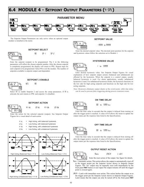
6.4 MODULE 4 - SETPOINT OUTPUT PARAMETERS (4-SPt)<br />
PARAMETER MENU<br />
The Setpoint Output Parameters are only active when an optional output<br />
module is installed in the meter.<br />
SPSEL<br />
<br />
<br />
NO<br />
SETPOINT SELECT<br />
NO<br />
SP-1<br />
SP-2<br />
Enter the setpoint (output) to be programmed. The n in the following<br />
parameters will reflect the chosen setpoint number. After the chosen setpoint<br />
is completely programmed, the display will return to SPSEL. Repeat steps for<br />
each setpoint to be programmed. Select NO to exit the module. The number of<br />
setpoints available is setpoint output card dependent.<br />
Enb-2<br />
<br />
<br />
NO<br />
YES<br />
SETPOINT 2 ENABLE<br />
NO<br />
Select YES to enable Setpoint 2 and access the setup parameters. If NO is<br />
selected, the unit returns to SPSEL and setpoint 2 is disabled.<br />
SPt-n <br />
10000<br />
HYS-n<br />
<br />
<br />
2<br />
SETPOINT VALUE<br />
-19999 to 99999<br />
Enter the desired setpoint value. The decimal point position for the setpoint<br />
and hysteresis values follow the selection set in Module 1.<br />
HYSTERESIS VALUE<br />
1 to 59999<br />
Enter desired hysteresis value. See Setpoint Output Figures for visual<br />
explanation of how setpoint output actions (balanced and unbalanced) are<br />
affected by the hysteresis. When the setpoint is a control output, usually<br />
balanced hysteresis is used. For alarm applications, usually unbalanced<br />
hysteresis is used. For unbalanced hysteresis modes, the hysteresis functions on<br />
the low side for high acting setpoints and functions on the high side for low<br />
acting setpoints.<br />
Note: Hysteresis eliminates output chatter at the switch point, while time delay<br />
can be used to prevent false triggering during process transient events.<br />
Act-n <br />
HI-Ub<br />
SETPOINT ACTION<br />
HI-bL<br />
LO-bL<br />
HI-Ub<br />
LO-Ub<br />
Enter the action for the selected setpoint (output). See Setpoint Output<br />
Figures for a visual detail of each action.<br />
tON-n<br />
<br />
<br />
0.0<br />
ON TIME DELAY<br />
0.0 to 599.9 Sec<br />
Enter the time value in seconds that the output is delayed from turning on<br />
after the trigger point is reached. A value of 0.0 allows the meter to update the<br />
output status per the response time listed in the Specifications.<br />
HI-bL =<br />
LO-bL =<br />
HI-Ub =<br />
LO-Ub =<br />
High Acting, with balanced hysteresis<br />
Low Acting, with balanced hysteresis<br />
High Acting, with unbalanced hysteresis<br />
Low Acting, with unbalanced hysteresis<br />
tOF-n<br />
<br />
<br />
0.0<br />
OFF TIME DELAY<br />
0.0 to 599.9 Sec<br />
Enter the time value in seconds that the output is delayed from turning off<br />
after the trigger point is reached. A value of 0.0 allows the meter to update the<br />
output status per the response time listed in the Specifications.<br />
High Acting (Balanced Hys) = HI-bL<br />
High Acting (Unbalanced Hys) = HI-Ub<br />
Low Acting (Balanced Hys) = LO-bL<br />
Low Acting (Unbalanced Hys) = LO-Ub<br />
rSt-n <br />
Auto<br />
OUTPUT RESET ACTION<br />
Auto<br />
LAtCH<br />
L-dLY<br />
Enter the reset action of the output. See figure for details.<br />
Auto = Automatic action; This action allows the output to automatically reset off<br />
at the trigger points per the Setpoint Action shown in Setpoint Output<br />
Figures. The “on” output may be manually reset (off) immediately by the<br />
front panel RST button or user input.The output remains off until the trigger<br />
point is crossed again.<br />
LAtCH = Latch with immediate reset action; This action latches the output on at<br />
the trigger point per the Setpoint Action shown in Setpoint Output Figures.<br />
Latch means that the output can only be turned off by the front panel RST<br />
10