CUB5P Data Sheet/Manual PDF - Ritec
CUB5P Data Sheet/Manual PDF - Ritec
CUB5P Data Sheet/Manual PDF - Ritec

You also want an ePaper? Increase the reach of your titles
YUMPU automatically turns print PDFs into web optimized ePapers that Google loves.
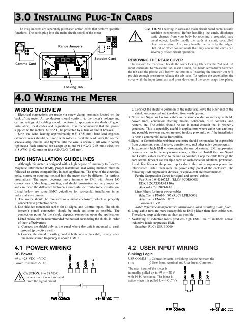
3.0 INSTALLING PLUG-IN CARDS<br />
The Plug-in cards are separately purchased option cards that perform specific<br />
functions. The cards plug into the main circuit board of the meter<br />
Comms Card<br />
Range Jumpers<br />
Setpoint Card<br />
CAUTION: The Plug-in cards and main circuit board contain static<br />
sensitive components. Before handling the cards, discharge<br />
static charges from your body by touching a grounded bare<br />
metal object. Ideally, handle the cards at a static controlled<br />
clean workstation. Also, only handle the cards by the edges.<br />
Dirt, oil or other contaminants that may contact the cards can<br />
adversely affect circuit operation.<br />
REMOVING THE REAR COVER<br />
To remove the rear cover, locate the cover locking tab below the 2nd and 3rd<br />
input terminals. To release the tab, insert a small, flat blade screwdriver between<br />
the tab and the plastic wall below the terminals. Inserting the screwdriver will<br />
provide enough pressure to release the tab locks. To replace the cover, align the<br />
cover with the input terminals and press down until the cover snaps into place.<br />
Locking Tab<br />
4.0 WIRING THE METER<br />
WIRING OVERVIEW<br />
Electrical connections are made via screw-clamp terminals located on the<br />
back of the meter. All conductors should conform to the meter’s voltage and<br />
current ratings. All cabling should conform to appropriate standards of good<br />
installation, local codes and regulations. It is recommended that the power<br />
supplied to the meter (DC or AC) be protected by a fuse or circuit breaker.<br />
Strip the wire, leaving approximately 0.3" (7.5 mm) bare lead exposed<br />
(stranded wires should be tinned with solder.) Insert the lead under the correct<br />
screw-clamp terminal and tighten until the wire is secure. (Pull wire to verify<br />
tightness.) Each terminal can accept up to one #14 AWG (2.55 mm) wire, two<br />
#18 AWG (1.02 mm), or four #20 AWG (0.61 mm).<br />
EMC INSTALLATION GUIDELINES<br />
Although this meter is designed with a high degree of immunity to Electro-<br />
Magnetic Interference (EMI), proper installation and wiring methods must be<br />
followed to ensure compatibility in each application. The type of the electrical<br />
noise, source or coupling method into the meter may be different for various<br />
installations. The meter becomes more immune to EMI with fewer I/O<br />
connections. Cable length, routing, and shield termination are very important<br />
and can mean the difference between a successful or troublesome installation.<br />
Listed below are some EMC guidelines for successful installation in an<br />
industrial environment.<br />
1. The meter should be mounted in a metal enclosure, which is properly<br />
connected to protective earth.<br />
2. Use shielded (screened) cables for all Signal and Control inputs. The shield<br />
(screen) pigtail connection should be made as short as possible. The<br />
connection point for the shield depends somewhat upon the application.<br />
Listed below are the recommended methods of connecting the shield, in order<br />
of their effectiveness.<br />
a. Connect the shield only at the panel where the unit is mounted to earth<br />
ground (protective earth).<br />
b. Connect the shield to earth ground at both ends of the cable, usually when<br />
the noise source frequency is above 1 MHz.<br />
4.1 POWER WIRING<br />
DC Power<br />
+9 to +28 VDC: +VDC<br />
Power Common: -VDC<br />
CAUTION: 9 to 28 VDC<br />
power circuit is not isolated<br />
from the signal circuit.<br />
c. Connect the shield to common of the meter and leave the other end of the<br />
shield unconnected and insulated from earth ground.<br />
3. Never run Signal or Control cables in the same conduit or raceway with AC<br />
power lines, conductors feeding motors, solenoids, SCR controls, and<br />
heaters, etc. The cables should be ran in metal conduit that is properly<br />
grounded. This is especially useful in applications where cable runs are long<br />
and portable two-way radios are used in close proximity or if the installation<br />
is near a commercial radio transmitter.<br />
4. Signal or Control cables within an enclosure should be routed as far as possible<br />
from contactors, control relays, transformers, and other noisy components.<br />
5. In extremely high EMI environments, the use of external EMI suppression<br />
devices, such as ferrite suppression cores, is effective. Install them on Signal<br />
and Control cables as close to the unit as possible. Loop the cable through the<br />
core several times or use multiple cores on each cable for additional protection.<br />
Install line filters on the power input cable to the unit to suppress power line<br />
interference. Install them near the power entry point of the enclosure. The<br />
following EMI suppression devices (or equivalent) are recommended:<br />
Ferrite Suppression Cores for signal and control cables:<br />
Fair-Rite # 0443167251 (RLC# FCOR0000)<br />
TDK # ZCAT3035-1330A<br />
Steward # 28B2029-0A0<br />
Line Filters for input power cables:<br />
Schaffner # FN610-1/07 (RLC# LFIL0000)<br />
Schaffner # FN670-1.8/07<br />
Corcom # 1 VR3<br />
Note: Reference manufacturer’s instructions when installing a line filter.<br />
6. Long cable runs are more susceptible to EMI pickup than short cable runs.<br />
Therefore, keep cable runs as short as possible.<br />
7. Switching of inductive loads produces high EMI. Use of snubbers across<br />
inductive loads suppresses EMI.<br />
Snubber: RLC# SNUB0000.<br />
4.2 USER INPUT WIRING<br />
Sinking Logic<br />
USR COMM Connect external switching device between the<br />
USR }User Input terminal and User Input Common.<br />
The user input of the meter is<br />
internally pulled up to +9 to +28 V<br />
with 10 K resistance. The input is<br />
active when it is pulled low (