Interactive 4D Overview and Detail Visualization in Augmented Reality
Interactive 4D Overview and Detail Visualization in Augmented Reality
Interactive 4D Overview and Detail Visualization in Augmented Reality

Create successful ePaper yourself
Turn your PDF publications into a flip-book with our unique Google optimized e-Paper software.
Interaction Methods<br />
Change Camera<br />
View<br />
Filter<strong>in</strong>g<br />
Select<br />
Attributes<br />
Select Time-<br />
<strong>Visualization</strong> Method<br />
Select Objects<br />
Select Po<strong>in</strong>ts on<br />
Object<br />
Select Po<strong>in</strong>ts <strong>in</strong> Time<br />
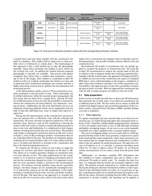
<strong>Interactive</strong> Transition Modes<br />
<strong>Overview</strong> &<br />
<strong>Detail</strong><br />
Focus &Context<br />
WIM<br />
Zoom<strong>in</strong>g<br />
2D GUI Slider<br />
2D GUI Slider<br />
2D GUI<br />
Sp<strong>in</strong>box<br />
2D GUI<br />
Sp<strong>in</strong>box<br />
2D GUI, Combobox -<br />
2D GUI, Combobox -<br />
Overlay - - - 2D GUI, Combobox<br />
Magic Lens - - - 2D GUI, Combobox<br />
Distorted View - - - 2D GUI, Combobox<br />
Mouse-Input on<br />
Scene<br />
Mouse-Input on<br />
Scene<br />
Mouse-Input on<br />
Scene<br />
Mouse-Input on<br />
Scene<br />
Mouse-Input on<br />
Scene<br />
- 2D GUI Slider<br />
- 2D GUI Slider<br />
Mouse-Input on<br />
Object<br />
Mouse-Input on<br />
Object<br />
Mouse-Input on<br />
Object<br />
Mouse-Input on Object<br />
<strong>Overview</strong>, 2D GUI Slider<br />
Mouse-Input on Object<br />
<strong>Overview</strong>, 2D GUI Slider<br />
Mouse-Input on Object<br />
<strong>Overview</strong>, 2D GUI Slider<br />
Figure 10: <strong>Overview</strong> of <strong>in</strong>teractive transition modes with their correspond<strong>in</strong>g <strong>in</strong>teraction methods.<br />
a regular basis <strong>and</strong> store them together with the construction site<br />
plans <strong>in</strong> a database. This enables staff or supervisors to relate possible<br />
errors or bottlenecks to certa<strong>in</strong> dates. The disadvantage of<br />
this approach is that a staff member has to take the photographs<br />
manually, be<strong>in</strong>g time-consum<strong>in</strong>g <strong>and</strong> lead<strong>in</strong>g to areas which are<br />
not covered very well. In addition the relation between acquired<br />
photographs is typically not available. Discussions with partner<br />
companies have shown that a complete data acquisition, consist<strong>in</strong>g<br />
of sets of 2D images, their relation to a generated as-built 3D<br />
model as well as to synthetic model plan, the relation over time <strong>and</strong><br />
<strong>in</strong> particular lucid visualization techniques are essential, <strong>and</strong> thus a<br />
highly <strong>in</strong>terest<strong>in</strong>g research area to optimize the documentation <strong>and</strong><br />
monitor<strong>in</strong>g process.<br />
A <strong>4D</strong> representation usually consist of 3D reconstructions accurately<br />
generated at relevant po<strong>in</strong>ts <strong>in</strong> time. These timestamps can<br />
be def<strong>in</strong>ed milestones with<strong>in</strong> the executed project management, but<br />
also po<strong>in</strong>ts that are taken from a regular basis. Hav<strong>in</strong>g 3D models<br />
at different po<strong>in</strong>ts <strong>in</strong> time provides the possibility to extensively<br />
observe the construction site from arbitrary, very <strong>in</strong>teractive, view<strong>in</strong>g<br />
positions. Additionally, the <strong>4D</strong> scene <strong>in</strong>formation serves as an<br />
important referenc<strong>in</strong>g platform which can be augmented with any<br />
k<strong>in</strong>d of data like <strong>in</strong>dividual laser scans or s<strong>in</strong>gle shots taken by a<br />
supervisor.<br />
Hav<strong>in</strong>g the <strong>4D</strong> representations of the constructions site process<br />
rises the question how to efficiently work with the collected <strong>and</strong><br />
related data. Of course, the data can then be explored <strong>in</strong> a VR visualization<br />
setup. However, such an VR visualization is miss<strong>in</strong>g the<br />
context of the real world, it is hard to visualize the different po<strong>in</strong>ts <strong>in</strong><br />
time <strong>in</strong> one view <strong>and</strong> furthermore it is complicated to f<strong>in</strong>d changes<br />
without switch<strong>in</strong>g between the data sets several times. The problem<br />
with simply overlay<strong>in</strong>g the construction data <strong>in</strong> an AR view is show<br />
<strong>in</strong> Figure 2, basic X-Ray techniques produce visualizations that are<br />
not comprehensible for the user. The problem of completely opaque<br />
render<strong>in</strong>g the reconstructed data is that a lot of the context <strong>in</strong>formation<br />
is occluded <strong>and</strong> therefore is miss<strong>in</strong>g <strong>in</strong> the visualization <strong>and</strong><br />
thus <strong>in</strong> the f<strong>in</strong>al documentation process.<br />
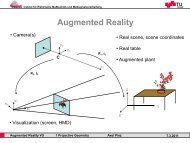
To visualize the <strong>4D</strong> data <strong>in</strong> context to real world, we apply the<br />
concept for overview <strong>and</strong> detail visualization of <strong>4D</strong> data <strong>in</strong> AR.<br />
This allows us to visualize geometric changes of construction sites<br />
over time directly on-site. The ma<strong>in</strong> requirements for the visualization<br />
is (1) to preserve context of chang<strong>in</strong>g environment <strong>and</strong> (2)<br />
see how the construction changed over time. It is important to note,<br />
that not every geometric change is relevant to the documentation<br />
process. For <strong>in</strong>stance, mov<strong>in</strong>g mach<strong>in</strong>es cause massive geometric<br />
changes, but these changes are not semantically mean<strong>in</strong>gful ones.<br />
(1) is achieved by us<strong>in</strong>g an on-site AR visualization, (2) by implement<strong>in</strong>g<br />
a visualization based on the overview <strong>and</strong> detail visualization<br />
for <strong>4D</strong> data. The ma<strong>in</strong> idea of our approach is to visualize this<br />
data <strong>in</strong> an AR view to preserve the context of the real world, which<br />
makes it for a construction site manager easier to reproduce <strong>and</strong> underst<strong>and</strong><br />
progress, <strong>and</strong> possible mistakes directly l<strong>in</strong>ked to the real<br />
construction site.<br />
Reconstructed 3D models of construction sites are already applied<br />
to visualize the progress of construction-sites. By us<strong>in</strong>g the<br />
as-built 3D reconstruction to analyze the current status of the site<br />
<strong>in</strong> relation to the as-planned model <strong>and</strong> overlay<strong>in</strong>g registered photographs<br />
with the as-built status, the approach of Golparvar-Fard et<br />
al. enables an overview of the construction site status [7]. Prepared<br />
BIM data is color-coded depend<strong>in</strong>g on the progress, completion or<br />
other values <strong>and</strong> overlaid to a distance view of the construction site.<br />
Nevertheless, this approach does not provide a possibility to <strong>in</strong>spect<br />
the data <strong>in</strong> detail over time. With our approach the construction site<br />
staff are able to <strong>in</strong>spect progress <strong>in</strong> relation to the real-world.<br />
5.1 Data preparation<br />
In this section we briefly describe how to derive the <strong>4D</strong> <strong>in</strong>formation<br />
that represents the as-built status of an observed construction site<br />
at different po<strong>in</strong>t <strong>in</strong> time. We first schow how to derive as-built <strong>4D</strong><br />
models from digital imagery <strong>and</strong> second the preparation of the synthetic<br />
models, extracted from CAD data or BIMs, <strong>and</strong> their l<strong>in</strong>kage<br />
over time is expla<strong>in</strong>ed.<br />
5.1.1 Data captur<strong>in</strong>g<br />
To capture mean<strong>in</strong>gful <strong>and</strong> time-oriented data at an observed construction<br />
site, we exploit fly<strong>in</strong>g helicopters like unmanned aerial vehicles<br />
(UAV). Typically, a def<strong>in</strong>ed flight-management has a duration<br />
of 10 to 20 m<strong>in</strong>utes <strong>and</strong> results <strong>in</strong> sets of 200-300 high-resolution<br />
<strong>and</strong> highly overlapp<strong>in</strong>g images. In our case we use a semi-manually<br />
controlled octo-copter equipped with a consumer digital camera.<br />
The set of overlapp<strong>in</strong>g images serves as ma<strong>in</strong> <strong>in</strong>put to a SfM approach<br />
[10] that results <strong>in</strong> the scene geometry composed of a sparse<br />
po<strong>in</strong>t cloud <strong>and</strong> the camera parameters. S<strong>in</strong>ce sparse geometry conta<strong>in</strong>s<br />
limited data for change detection <strong>and</strong> visualization we follow<br />
state-of-the-art methods for model densification. We apply the concept<br />
of Furukawa et al. to calculate a oriented semi-dense po<strong>in</strong>t<br />
cloud [5]. In order to obta<strong>in</strong> a dense 3D model, we use Poisson<br />
surface reconstruction [15] to create a mesh from the po<strong>in</strong>t cloud<br />
data.<br />
Additionally, we <strong>in</strong>troduce available GPS <strong>in</strong>formation <strong>in</strong>to<br />
the workflow to reduce computation time <strong>and</strong> to obta<strong>in</strong> a georeferenced<br />
3D model at metric scale. To visualize the data over<br />
time, it is important that the meshes are accurately aligned to each<br />
other. We perform accurate registration <strong>in</strong> a multi-step approach.<br />
Hav<strong>in</strong>g the <strong>in</strong>itial geo-reference <strong>in</strong>formation enables a coarse registration<br />
of the <strong>in</strong>dividual models over time. In a second step we apply<br />
a match<strong>in</strong>g procedure on accumulated feature descriptors available<br />
for the sparse 3D po<strong>in</strong>ts (result<strong>in</strong>g from the SfM). S<strong>in</strong>ce coarse<br />
registration is already available, the match<strong>in</strong>g can be applied to