Husky 10 Foam
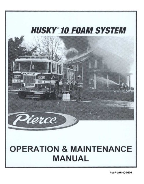
Husky 10 Foam
Husky 10 Foam
You also want an ePaper? Increase the reach of your titles
YUMPU automatically turns print PDFs into web optimized ePapers that Google loves.
PM-F-OM140-0804
QmCK REFERENCE OPERATING INSTRUCTIONS<br />
PIERCE HUSKY <strong>10</strong> I HERCULES FOAM SYSTEM<br />
TO MAKE CLASS A FOAM<br />
1. Turn foam system "ON" with control switch on Red <strong>Husky</strong> control panel.<br />
2. Open water discharge valve and begin to flow from hose line.<br />
3. Set to the desired percentage (normal default is A onboard tank@ 0.5%).<br />
4. You are now making foam solution.<br />
TO SHUT DOWN AFTER CLASS A FOAM<br />
1. Turn foam system "OFF" with control switch on Red <strong>Husky</strong> control panel.<br />
2. Open the water discharge valve on the discharge(s) that were used and begin to<br />
flow from hose line until the water from the hose runs clear.<br />
3. Disengage water pwnp and open all manifold drains and water drains to relieve<br />
any trapped pressure.<br />
4. Close all drains and valves. The system is now ready to be put back into service.<br />
TO MAKE CLASS A COMPRESSED AIR FOAM (CAF)<br />
1. Turn foam systcm "ON" with control switch on Red <strong>Husky</strong> control panel.<br />
2. Turn air compressor "ON", (under <strong>10</strong>00 engine RP .M.) on the blue Hercules<br />
control panel.<br />
3. Open water discharge valve and begin to flow from hose line.<br />
4. Set to the desired percentage (nonnal default is 0.5%).<br />
5. You are now making foam solution.<br />
6. Turn on the air injection to the corresponding discharge with the toggle switch<br />
located by the discharge valve control.<br />
7. You are now making compressed air foam.<br />
8. Adjust the "WET" / "DRY" ratio of the compressed air foam by opening or<br />
closing the water discharge valve. The more the water valve is opened the<br />
~etter" the CAP will be.<br />
TO SHUT DOWN AFTER CLASS A COMPRESSED AIR FOAM (CAF)<br />
1. Turn off all air injection switches (compressor may be turned off at this point if<br />
no longer needed).<br />
2. Turn foam system "OFF" with control switch on Red <strong>Husky</strong> control panel.<br />
3. Open the water valve to the discharge( s) that were used and begin to flow from<br />
hose line until the water from the hose nms clear.<br />
4. Shut off water valve to the discharge.<br />
5. Turn off the compressor on the blue Hercules control panel.<br />
6. Disengage water pump and open all manifold drains and water drains to relieve<br />
any trapped pressure. Close all valves/drains. System is ready to be put back into<br />
servIce.<br />
NOTE: System shut down and flushing can be started during MOP UP, this way all foam<br />
is used on the fIre.<br />
A
QUICK REFERENCE OPERATING INSTRUcnONS<br />
PIERCE HUSKY <strong>10</strong> I HERCULES FOAM SYSTEM<br />
TO MAKE CLASS B FOAM<br />
1. Turn foam system "ON" with control switch on Red <strong>Husky</strong> control panel.<br />
2. Open water discharge valve and begin to flow from hose line.<br />
3. Push "Mode" button on red <strong>Husky</strong> control panel until "CLASS B FOAM" OR<br />
"DRAFf CLASS B" comes up, hit ENTER to make selection. An automatic<br />
flush will occur for 15 seconds. Put pickup tube in pail if using off board foam<br />
(You must open the foam inlet valve ifusing draft option).<br />
4. You are now making foam solution.<br />
5. Turn on the air injection to the corresponding discharge with the toggle switch<br />
located by the discharge valve control.<br />
6. You are now making compressed air foam.<br />
7. Adjust the "WET" / "DRY" ratio of the compressed air foam by opening or<br />
closing the water discharge valve. The more the water valve is opened the<br />
"wetter" the CAF will be.<br />
TO SHUT DOWN AFTER CLASS B FOAM OR DRAFrlNG A DIFFERENT<br />
BRAND OF CLASS A FOAM<br />
1. Continue flowing water through discharges used.<br />
. If the off board foam inlet was used, open the offboard pick up valve and<br />
draft clear water through this line for 1 to 2 minutes. Turn up % to draft more<br />
flush water though the system.<br />
2. Turn the "CAUFLUSH - INJECT" (valve generally mounted behind the d/s<br />
pump panel) to cal/flush. Mode is indicated when verbiage is horizontal.<br />
. On display go to Flush Mode push Enter and release push Enter a second<br />
time and hold.<br />
. Return Call Flush valve to inject when raw foam is no longer visible.<br />
Continue flowing though discharges until they too are clear. Release Enter<br />
button. Drop down to a single discharge line.<br />
3. On red <strong>Husky</strong> panel press MODE button until "CLASS A FOAM" appears, press<br />
ENTER (15 second flush will occur automatically).<br />
4. Open the water discharge valve on a foam discharge. Flow water through this<br />
discharge until class A foam appears. Shut off <strong>Husky</strong> <strong>10</strong>. Continue flowing<br />
though discharge until it again is clear of foam.<br />
5. Disengage water pump and open all manifold drains and water drains to relieve<br />
any trapped pressure.<br />
6. Top off foam tanks.<br />
7. System is ready to be put back in service.<br />
TANK FILL OPTION<br />
I. Open II.. turn valve on panel to open, close when done.<br />
2. Fill A tank only though "foam inlet valve".<br />
3. Fill B tank though "B foam inlet" (this is the only time this inlet is used).<br />
B
kciuQ Reference Operating Instructions<br />
elbaT of Contents<br />
ytefaS Information<br />
TABLE OF CONTENTS<br />
.Inside Front Cover<br />
TC-l to TC-3:<br />
i<br />
SCHEMATICS<br />
Fig 1-<br />
<strong>Husky</strong> <strong>10</strong> <strong>Foam</strong> System Schematic<br />
..11<br />
CHAPTER I-INTRODUCTION<br />
1-1<br />
1-2<br />
1-3<br />
1-4<br />
General Description 1-1<br />
System Capacity 1-1<br />
JFo~ Concentrate CoDlpati1Jility 1-~<br />
JFo~ SysteDl CoDlponents and JFunctions 1-~<br />
A. Hydraulic Drive SysteDl 1-~<br />
1. Hydraulic GearPUDlp 1-~<br />
2. Hydraulic JFilter 1-3<br />
3. Hydraulic Tank 1-3<br />
4. Hydraulic Cooler ; 1-4<br />
5. Hydraulic Manifold Block 1-4<br />
a. Hydraulic ~oportional 'lalve 1-4<br />
B. JFo~ Supply System 1-5<br />
1.. JFo~ Concentrate Tank 1-5<br />
2. JFo~ Tank Drain 'lalve 1-5<br />
3. JFo~ Tank ShutofI'lalve 1-5<br />
4. Auxiliary JFo~ Inlet 1-5<br />
5. Inline JFo~ Strainer 1-6<br />
6. JFo~ Concentrate Pump 1-6<br />
7. Ca1i1Jrate-JFlush /Fo~ Inject 'lalve. 1-6<br />
8. JFo~ Check 'lalve 1-7<br />
9. JFo~ Injection Manifold 1-7<br />
C. Water Supply SysteDl 1-7<br />
1. Inline Water Check 'lalve 1-'1<br />
2. Water JFlow Meter 1-7<br />
a. JFOaln Meter Installation Tee... ... 1-7<br />
D. JFo~ System Controls 1-8<br />
1. JFo~ System Controller 1-8<br />
2. JFo~ System Control Head 1-8<br />
TC-l
.AgnisecA Set Up Mode Screns<br />
.A Calibrate FlowmeterMode<br />
.B Calibrate <strong>Foam</strong> Pump Transducer.J<br />
.D.C Calibrate Clas A <strong>Foam</strong> Mode<br />
.E Calibrate Clas B <strong>Foam</strong> Mode<br />
teS Up, Calibration Procedures.<br />
Set Up Mode<br />
Set Default <strong>Foam</strong> Source<br />
CHAPTER 2 - INITIAL FOAM FILL AND SYSTEM CHARGING<br />
2-1<br />
2-2<br />
2-5<br />
CHAPTER 3 - OPERATING PROCEDURES<br />
3-1<br />
3-2<br />
3-4<br />
<strong>Husky</strong> <strong>10</strong> Stand-By Mode ... 3-1<br />
OperatingProcedures 3-1<br />
A. <strong>Husky</strong> <strong>10</strong> <strong>Foam</strong> System Activation 3-1<br />
B. Changing <strong>Foam</strong> Source 3-2<br />
C. Stopping <strong>Foam</strong> Solution Flow (Maintaining Water Flow).. 3-2<br />
D. Priming <strong>Foam</strong> System (Manual) 3-2<br />
E. Flushing <strong>Foam</strong> System (Manual) 3-3<br />
Flowmeter Manual Override 3-3<br />
A. Manual Mode Operation 3-3<br />
B. Flowmeter Mode Operation 3-4<br />
Using Auxiliary Pickup Connection As <strong>Foam</strong> Source 3-4<br />
A. Description 3-4<br />
B. Using Auxiliary Pickup Connection As <strong>Foam</strong> Source 3-5<br />
CHAPTER 4 - DISPLAY MODE<br />
Display Mode<br />
4-1<br />
CHAPTER 5 - SET UP & CALIBRA nON PROCEDURES<br />
5-1<br />
5-2<br />
F. Set Class A Concentrate Default Percentage...<br />
G. Set Class B Concentrate Default Percentage...<br />
5-1<br />
5-1<br />
5-1<br />
5-1<br />
, 5-2<br />
5-2<br />
5-4<br />
5-5<br />
5-5<br />
5-6<br />
TC-2
H.<br />
I.<br />
J.<br />
K.<br />
L.<br />
M.<br />
N.<br />
O.<br />
Set Default System Units 5-6<br />
Set Automatic Flush Time 5-6<br />
Reset <strong>Foam</strong> Strainer Maintenance Reminder 5-7<br />
Reset Water Strainer Maintenance Reminder 5-7<br />
Reset Hydraulic Fluid Maintenance Reminder 5-7<br />
Select Single or Dual <strong>Foam</strong> Tank System 5-8<br />
Select Optional Tank Fill Settings... 5-8<br />
Check Current Software Revision 5-8<br />
CHAPTER 6 - INSPECTION. MAINTENANCE AND REPAIR<br />
6-1<br />
6-2<br />
6-3<br />
6-4<br />
6-7<br />
Inspection And Maintenance 6-1<br />
Testing After System Maintenance 6-1<br />
Periodic Operation 6-1<br />
Recommended Hydraulic Oil For <strong>Husky</strong> <strong>10</strong> Proportioning System. 6-2<br />
A. Characteristics 6-2<br />
B. Recommendations 6-2<br />
Hydraulic Filter Cleaning and Replacement 6-2<br />
A. FilterReplacement 6-2<br />
In-Line Y -Strainer Maintenance 6-2<br />
A. <strong>Foam</strong> Feed Line Y-Strainer 6-2<br />
B. Flush/Cooling Water Y-Strainer .'.." 6-3<br />
Maintenance After Every Use 6-3<br />
CHAPTER7-TROUBLESHOOTING<br />
- -- -- --<br />
7-1<br />
1-2<br />
lareneG Troubleshooting Information Matrix. .. ... ...<br />
7-1<br />
, 7-1<br />
TC-3
SAFETY INFORMATION<br />
Warning<br />
This manual has been prepared as an aid and guide for personnel involved in<br />
the start-up, operation and maintenance of the Pierce <strong>Husky</strong> <strong>10</strong> <strong>Foam</strong><br />
Proportioning System. All instructions must be read and understood<br />
thoroughly before attempting any start-up, operation or maintenance to this<br />
system and its related equipment. Failure to follow any instructions could<br />
result in personal injury and/or damage to this equipment.
~<br />
~~<br />
T.b)IK UN[<br />
r-O-
PUW'MM
THIS PAGE INTENTIONALLY LEFT BLANK
INTRODUCTION<br />
GENERAL<br />
.<br />
DESCRIPTION<br />
The <strong>Husky</strong> <strong>10</strong> <strong>Foam</strong> System operates as an On-Demand system by measuring water flow<br />
and injecting the required foam based on an operator defined percentage. <strong>Foam</strong> is drawn<br />
from either an on-board foam tank or through a draft hose from an alternate foam source,<br />
such as a curbside container.<br />
The foam concentrate is injected into a manifold, which distributes the foam/water<br />
solution to all designated discharges. Check valves in both the water line and foam line<br />
prevent contamination of the water and foam supplies.<br />
Options are available to use the foam system to fill the on-board foam tank(s) through the<br />
draft hose, eliminating the need to hoist buckets of foam to the top of the truck for<br />
pouring into the tank(s).<br />
The system is designed to supply foam concentrate at a maximum of <strong>10</strong> GPM and 400<br />
PSI operating pressure. The display will provide a message when the setpoint exceeds<br />
the maximum <strong>10</strong> GPM. <strong>Foam</strong>/water mixture can be delivered from any combination of<br />
discharge outlets with the same proportion being delivered to each one.<br />
Maximum <strong>Foam</strong> Solution Flow<br />
<strong>Foam</strong> Concentrate Water Flow<br />
(0.01-<strong>10</strong> GPM)<br />
6% 166 GPM<br />
3% 333 GPM<br />
2% 500 GPM<br />
1%<br />
0.5%<br />
1,000 GPM.<br />
2,000 GPM .<br />
- Maximum water flow will depend on plumbing restrictions
INTRODUCTION<br />
The <strong>Husky</strong> <strong>10</strong> <strong>Foam</strong> System is designed to be compatible with most known Class A and<br />
Class B foam concentrates at the date of printing of this manual. The <strong>Husky</strong> <strong>10</strong> can<br />
proportion foam concentrates across a wide range of viscosities, from low viscosities<br />
such as Class A or Class B AFFF, through high viscosities such as Class B AR-AFFF.<br />
NOTE:<br />
To understand the relationship of the various components and their functions,<br />
please refer to the <strong>Husky</strong> <strong>10</strong> Schematic, Figure 1-1. The following<br />
information is intended to identify the various components and describe their<br />
function within the system.<br />
A. Hydraulic Drive System: The trucks engine and transmission are the power source<br />
for <strong>Husky</strong> <strong>10</strong> hydraulic drive system. The foam pump is driven by pressurized<br />
hydraulic fluid supplied by a hydraulic gear pump directly coupled to the water pump<br />
drive or power take-off driven off the truck transmission. The hydraulic system<br />
pressure and flow is regulated by a hydraulic manifold block that contains relief<br />
valves to protect the system from being over pressurized, and a proportional valve<br />
that controls direction and flow volume of the hydraulic fluid.<br />
1 The Hydraulic Gear Pump is a shaft driven gear pump mounted either directly<br />
to the water pump drive unit or PTO driven off the truck transmission. The<br />
hydraulic system is operational anytime the water pump drive is engaged.<br />
1-2
INTRODUcnON<br />
2. The Hydraulic Filter is a pressure bypass element-type filter manufactured by<br />
Hydac. The filter element is replaceable. The unit is installed inside the<br />
pumphouse and is used to filter the pressurized hydraulic loop. See Figure 1-1 for<br />
process location in the system. The part number for the replacement filter<br />
element is Hydac PN 0055DOIOBN3HC.<br />
3. The Hydraulic Tank (approximately 4 gallons) provides a reservoir for the<br />
hydraulic drive system. The tank is sufficient size to minimize foaming of the<br />
hydraulic fluid and is located to facilitate checking level and adding oil. Refer to<br />
Sect. 6-4 for Recommended Hydraulic Oil for the <strong>Husky</strong> <strong>10</strong> system.<br />
1-3
INTRODUCTION<br />
4 The Hydraulic Cooler is an oil-to-water type heat exchanger. It takes water<br />
directly from the water pump to cool the closed loop hydraulic system. The<br />
cooling water is then returned to the water pump suction while the cooled<br />
hydraulic oil is returned to the hydraulic tank. The hydraulic cooler allows for<br />
continual operation of the <strong>Husky</strong> <strong>10</strong> hydraulic system.<br />
s The Hydraulic Manifold Block assembly is a manifold block that controls the<br />
direction of the hydraulic oil flow in the system. The manifold block consists of<br />
the machined block, a hydraulic compensating valve. an internal hydraulic shuttle<br />
valve, a hydraulic relief valve, hydraulic pressure test port and the hydraulic<br />
proportional valve.<br />
a. The Hydraulic Proportional Valve controls the direction and volwne of<br />
hydraulic fluid to the hydraulic end of the foam pump. This controls the rate<br />
of displacement of foam from the foam pump.<br />
1-4
INTRODUcnON<br />
B. <strong>Foam</strong> Snooty System: The foam supply system stores, pumps and distributes the<br />
foam concentrate to the foam/water discharges by use of a foam concentrate tank,<br />
foam tank shut-otIvalve, auxiliary foam inlet, inline foam strainer, foam pump, check<br />
valve and foam injection manifold.<br />
1. The <strong>Foam</strong> Concentrate Tank is designed to provide on-board storage of foam<br />
concentrate. Design features shall include: construction compatible with foam<br />
concentrates, foam tank drain valve, expansion dome with locking fill hatch and<br />
pressure vacuum vent. The expansion dome allows for changes in foam<br />
concentrate volume due to variations in temperature. <strong>Foam</strong> concentrate level<br />
shall be maintained at the one-third full mark in the expansion dome at a<br />
minimum to reduce the air to foam concentrate interface. The pressure vacuum<br />
vent automatically balances internal foam tank pressure under both suction and<br />
filling operations. It is recommended that a cleanable foam concentrate level unit<br />
be installed in the storage tank.<br />
2. The <strong>Foam</strong> Tank Drain Valve is a manually operated gate valve. It is located<br />
behind the passenger side pump panel.<br />
3 The <strong>Foam</strong> Tank Sbut-off Valve is an electrically actuated, non-gateable ball<br />
valve. Its position is controlled by the <strong>Husky</strong> <strong>10</strong> foam control system.<br />
4 The Auxiliary <strong>Foam</strong> Inlet is located on the pump operator's panel and consists<br />
of a foam pick-up hose, a panel-mounted connection, a manually operated shutoff<br />
valve and a check-valve. This 1" diameter inlet allows for foam to be drafted<br />
from an off-board source such as a foam pail, canister, tote, etc. This allows for<br />
use of a different type or class of foam than what is currently stored in the foam<br />
tank, or for continued use of the foam system after the foam tank is empty.<br />
1-5
INTRODUCfION<br />
s.<br />
The Inline <strong>Foam</strong> Strainer is located before the inlet to the foam pump and<br />
screens all foam and flush water before it enters the foam pump. The strainer<br />
contains a removable 20-mesh screen basket.<br />
6. The <strong>Foam</strong> Concentrate Pump assembly is a brass/steel constructed, doubleacting<br />
cylinder pump. The hydraulic end of the pump is painted steel and controls<br />
the speed and direction of both cylinders. The hydraulic piston is connected to<br />
the foam piston by a single, straight shaft. The foam end of the pump is brass<br />
construction and contains 4 cartridge type check valves to prevent foam from<br />
flowing the wrong direction in the pump. The foam pump also has a pressure<br />
relief valve that recirculates the foam from the discharge side to the inlet side in<br />
the case of an obstruction or oveIpressure situation. The foam pump is speed and<br />
operation are monitored by a foam pump transducer located in the hydraulic end<br />
of the pump assembly.<br />
7.<br />
The Calibrate-Flush/<strong>Foam</strong> Inject Valve is a 3- way, quarter-turn ball valve that<br />
directs the foam either to a ground discharge or to the foam injection manifold.<br />
The valve is located immediately after the discharge of the <strong>Foam</strong> Concentrate<br />
Pump behind the driver side pump operator's panel.<br />
1-6
INTRODUCnON<br />
8.<br />
The <strong>Foam</strong> Check Valve located in the foam supply line prevents water from<br />
flowing backwards through the foam system and contaminating the foanl supply.<br />
9.<br />
The <strong>Foam</strong> Injection Manifold is the location where the foam is injected into the<br />
water supply and mixed for distribution to the foam/water discharges.<br />
C. Water Supply System: The water supply system supplies water to the foam injection<br />
manifold for foam to be added and distributed to the foam/water discharges. This<br />
system consists of an inline water check valve, water flow meter and flow meter<br />
installation tee. The size of the check valve and the flow meter installation tee are<br />
dependent on the number of foam/water discharges in the system.<br />
1<br />
The lnline Water Check Valve prevents foam from entering the water pump and<br />
the remainder of the water system. It is installed in the water piping, before the<br />
. . . the water flow meter.<br />
2.<br />
The Water Flow Meter measures the flow of water supplied to the foam/water<br />
discharges before foam is injected. This controls the amount of foam that is<br />
injected when the <strong>Husky</strong> <strong>10</strong> foam system is turned on.<br />
a.<br />
The Flow Meter Installation Tee is a stainless steel tee with standard<br />
grooved ends and a female NPT fitting for installing the water flow meter.<br />
1_'7
INTRODUcnON<br />
D. <strong>Foam</strong> System Controls: The foam system is controlled by a foam system controller<br />
module that contains the programming to actuate the appropriate valves, direct the<br />
hydraulic fluid, and control the injection rate of the foam. The user interfaces with<br />
the controller through the foam system control head.<br />
1 The <strong>Foam</strong> System Controller is an aluminum-enclosed unit that contains the<br />
electronic hardware and programming to control the various parts of the foam<br />
system.<br />
2. The <strong>Foam</strong> System Control Head is the operator interface with the foam system.<br />
It is located on the main pump panel. It has 6 operating buttons: System On/Off,<br />
Mode, Display, Enter, Arrow Up, Arrow Down. The display is a 2-line, 32<br />
character, LCD screen. System power is indicated by a red LED, and the foam<br />
pump operating is indicated by a green LED.<br />
1-8
INITIAL FOAM FILL AND SYSTEM CHARGING<br />
CAUTION: Do not mix different types or manufacturers brands of foam<br />
concentrate in the foam cells or piping. Mixing of different foam<br />
concentrates (either type or manufacturer) may cause deterioration of<br />
the foam concentrate, improper proportioning and poor performance in<br />
a fire situation. Mixing of Class A and Class B foam concentrates may<br />
result in a chemical reaction that can create globules, which can clog<br />
orifices and cause system failure.<br />
NOTE:<br />
Refer to the <strong>Husky</strong> <strong>10</strong> <strong>Foam</strong> System Schematic, Figure 1-1. For the<br />
purposes of this manual, it is assumed that Class A foam is the most<br />
commonly used agent and the system will be stored wet with Class A foam<br />
concentrate. If Class A foam is not the primary agent, adjust procedures to<br />
accommodate the primary foam concentrate.<br />
CAUTION: Do not mix different types or manufacturers brands of foam<br />
concentrate in the foam cells or piping. Mixing of different foam<br />
concentrates (either type or manufacturer) may cause deterioration of<br />
the foam concentrate, improper proportioning and poor performance in<br />
a fire situation. Mixing of Class A and Class B foam concentrates may<br />
result in a chemical reaction that can create globules, which can clog<br />
orifices and cause system failure.<br />
NOTE:<br />
Locate and close all foam tank and manifold drains. They may be found on<br />
and behind both the driver and passenger side pump panels.<br />
When filling the foam concentrate during a non-fire situation, the following procedure is<br />
recommended:<br />
The vehicle should be parked on a level surface or with the expansion dome of the<br />
tank slightly inclined.<br />
2.<br />
If filling from a pressurized source through the expansion dome hatch, the hose<br />
should be extended to the bottom of the tank to minimize frothing of the foam<br />
concentrate.<br />
2-1
INITIAL FOAM FILL AND SYSTEM CHARGING<br />
3. If foam concentrate must be added by pouring through the expansion dome hatch,<br />
it must be done slowly to prevent aeration. If aeration occurs inside the tank, stop<br />
pouring until the foam concentrate bubbles dissolve. Take care not to allow dirt<br />
or debris to enter the tank. Pour the foam concentrate down the center of the<br />
round tube when filling the tank. This tube goes into the tank and allows the<br />
foam concentrate to enter Wlder the surface of foam currently in the tank to reduce<br />
aeration of the foam per NFP A.<br />
2-3. CLASS A FOAM CONCENTRATE TANK FILLING INSTRUcrlONS<br />
(OPTIONAL FOAM TANK FILL)<br />
NOTE:<br />
Locate and close all foam tank and manifold drains. They may be found<br />
on and behind both the driver and passenger side pump panels.<br />
Connect water supply to water pump and fill the water pump in accordance with<br />
the apparatus manufacturer's recommended procedure.<br />
NOTE:<br />
The <strong>Husky</strong> <strong>10</strong> hydraulic drive system is driven by the water pump drive<br />
mechanism, and the water from the water pump system is used to cool the<br />
hydraulic fluid. The water pump must be re-circulating to prevent damage<br />
to pump components.<br />
CAUTION: Recirculating water through the water tank and water pump may<br />
not provide enough cooling over long running periods as the heat may<br />
not dissipate the heat adequately. Be careful to not overheat<br />
hydraulic system by using warm water for cooling the hydraulic fluid.<br />
2 Connect the draft hose to the <strong>Foam</strong> Inlet connection on the driver<br />
side pump panel and open the <strong>Foam</strong> Inlet valve.<br />
3.<br />
Verify that the Tank Fill/<strong>Foam</strong> Inject valve is in the TANK FILL<br />
position. This valve should be located behind the small door on<br />
the lower rear portion of the driver side pump panel. (Words in<br />
the horizontal position indicate the position of the valve. The<br />
valves shown in the photo below are in the TANK FILUFOAM<br />
INJECT position.)<br />
2-2
~<br />
INITIAL FOAM FILL AND SYSTEM CHARGING<br />
4.<br />
Turn the foam system on by pressing the<br />
SYSTEM ON/OFF button on the<br />
display. The display should read:<br />
5,<br />
Press the MODE button until the display<br />
reads:<br />
6. Press ENTER. The display should read:<br />
TANKA<br />
FILL<br />
7. Once the tank level has reached the upper level float switch, the display should<br />
read:<br />
TANKA<br />
FULL<br />
and automatically shut off the foam pump.<br />
8. The display should return to the main water flow screen and read:<br />
NOTE:<br />
WATER FLOW<br />
0000 GPM<br />
To reduce the entrance of air into the system when filling the tank, the<br />
operator should be prepared to transfer the pick-up tube from one pail to<br />
the next before the pail is completely empty.<br />
9.<br />
Turn the valve back to the FOAM INJECT position.<br />
2-3
INITIAL FOAM FILL AND SYSTEM CHARGING<br />
2-4. CLASS B FOAM CONCENTRATE TANK FILLING INSTRUCfIONS<br />
(OPrIONAL FOAM TANK FILL)<br />
NOTE:<br />
Locate and close all foam tank and manifold drains. They may be found<br />
on and behind both the driver and passenger side pump panels.<br />
1<br />
Connect the draft hose to the foam tank refill connection on either the driver side<br />
or passenger side pump panel and open the foam tank refill valve.<br />
2. Turn the foam system on by pressing the SYSTEM ON/OFF button on the<br />
display. The display should read:<br />
WATER FLOW<br />
0000 GPM<br />
3. Press the MODE button until the display reads:<br />
TANKB<br />
FILL<br />
4. Press ENTER. The display should read:<br />
TANKB<br />
FILLING<br />
5. Once the tank level has reached the upper level float switch, the display should<br />
read:<br />
TANKB<br />
FULL<br />
and automatically shut off the Class B foam fill pump.<br />
6.<br />
The display should return to the main water flow screen and read:<br />
WATER FLOW<br />
0000 GPM<br />
NOTE:<br />
Locate and close all foam tank and manifold drains. They may be found on<br />
and behind both the driver and passenger side pump panels.<br />
Class A <strong>Foam</strong> Concentrate is considered the primary agent. Fill <strong>Foam</strong> Cell A with Class<br />
A foam concentrate. The foam cell should be filled partway into the expansion dome to<br />
minimi7.e the surface area of foam concentrate subject to evaporation. If the automatic<br />
tank fill option was not selected with the system, pour foam concentrate down the center<br />
of the round tube when filling the tank. This tube goes into the tank and allows the foam<br />
concentrate to enter under the surface of foam currently in the tank. This is done to<br />
reduce the aeration of the foam concentrate per NFP A.<br />
2-4
INITIAL FOAM FILL AND SYSTEM CHARGING<br />
1<br />
Connect water supply to water pump and fill the water pump in accordance with<br />
the apparatus manufacturer's recommended procedure.<br />
NOTE:<br />
The <strong>Husky</strong> <strong>10</strong> hydraulic drive system is driven by the water pump drive<br />
mechanism, and the water from the water pump system is used to cool the<br />
hydraulic fluid. The water pump must be re-circulating to prevent damage<br />
to pump components.<br />
CAUTION: Recirculating water through the water tank and water pump may<br />
not provide enough cooling over long running periods as the heat may<br />
not dissipate the heat adequately. Be careful to not overheat hydraulic<br />
system by using warm water for cooling the hydraulic fluid.<br />
2.<br />
3.<br />
Press ENTER to select foam source, press the up or down arrow button to change<br />
the foam injection percentage, press ENTER to accept selection and return to<br />
original water flow screen. (This step can be skipped in the future if default foam<br />
source is verified to be Class A <strong>Foam</strong> at the appropriate percentage.)<br />
4.<br />
Verify that the Calibrate-Flush/<strong>Foam</strong> Inject valve is in the Calibrate-Flush<br />
position. This valve should be located behind the small door on the lower rear<br />
portion of the driver side pump panel. (If the automatic Tank Fill option is<br />
installed, the Tank Fill valve also needs to be in the <strong>Foam</strong> Inject position. This<br />
valve is also located behind the small door on the lower rear portion of the driver<br />
side panel.)<br />
2-5
INITIAL FOAM FILL AND SYSTEM CHARGING<br />
NOTE: Valve position is indicated by the horizontal positioning of the words.<br />
5. Press the MODE button until the<br />
display reads:<br />
Press ENTER to select the PRIME MODE. Press and hold the ENTER button<br />
until foam is coming out of the Calibrate-Flush line under truck. Then turn the<br />
valve to the <strong>Foam</strong> Inject position and hold ENTER button for 3 to 5 seconds.<br />
(Once the systeDl is completely primed, failure to release the ENTER button will<br />
cause the foam pump pressure relief valve to open. Pressure can be relieved by<br />
opening the manifold drain valve.)<br />
6. Press the SYSTEM ON/OFF button to turn the foam system off.<br />
7. Shutdown the water pump and the vehicle engine in accordance with the<br />
apparatus manufacturer's recommended procedure.<br />
NOTE: The foam concentrate system is now charged and is in stand-by.<br />
2-6
OPERATING PROCEDURES<br />
A. The foam system is in Stand-By Mode when:<br />
1. All valves are in their nonnal stand-by position.<br />
2.<br />
Water pump is primed and ready.<br />
3. No water is flowing out any foam/water discharge except to cool the water pump.<br />
4. <strong>Foam</strong> operation is anticipated from one or more discharge connections.<br />
s.<br />
6.<br />
The <strong>Husky</strong> <strong>10</strong> system is turned on and the SYSTEM ON light is lit.<br />
The appropriate foam source is selected (by default or by operator) and the foam<br />
system is charged.<br />
CAUTION:<br />
Before operating the <strong>Husky</strong> <strong>10</strong> System, operating personnel ~<br />
familiarize themselves with all procedures and instructions regarding<br />
the water pump, aerial device(s), discharge devices and foam making<br />
devices. Failure to understand and follow any instructions could<br />
result in personal injury and/or damage to this equipment.<br />
A. <strong>Husky</strong> <strong>10</strong> <strong>Foam</strong> System Activation<br />
1<br />
2.<br />
Engage the water pump in accordance with the pump manufacturer's instructions.<br />
Turn foam system on by pressing the SYSTEM ON/OFF button on the display.<br />
3. Place the Calibrate-Flush/<strong>Foam</strong> Inject valve in the <strong>Foam</strong> Inject position.<br />
NOTE:<br />
If tank fill option is installed, verify that Tank Fil1/<strong>Foam</strong> Inject valve is<br />
in the <strong>Foam</strong> Inject position.<br />
4.<br />
Begin water flow to the desired discharge(s) by opening the appropriate valve.<br />
5. Increase engine speed until desired discharge pressure is obtained.<br />
NOTE:<br />
If system was not charg~ operator can prime system as described in step<br />
5 of Section 2-5, SYSTEM CHARGING FROM THE ON-BOARD<br />
FOAM CONCENTRATE STORAGE CELL. This step can be completed<br />
at any time during normal operation. System will prime from whichever<br />
foam source is selected at that time.<br />
3-1
OPERATING PROCEDURES<br />
B. Changing <strong>Foam</strong> Source<br />
1. With foam system turned o~ press<br />
MODE button until desired foam<br />
source appears on display screen.<br />
2. Press ENTER to select new foam<br />
source.<br />
3. Press AITOw Up or Arrow Down to select desired foam injection percentage,<br />
4. Press ENTER to accept new foam source and injection percentage selection.<br />
NOTE:<br />
When changing from any Class A foam source to any Class B foam<br />
source, or reverse, the system will automatically flush the system with<br />
water from the water pump for 15 seconds. Operator needs to verify<br />
proper valves are opened/closedepending on where flush water is to be<br />
discharged. Recommendedischarge location for flush water would be<br />
the desired water discharge or handline(s).<br />
CAUTION: Do not mix different types or manufacturers brands of foam<br />
concentrate in the foam cells or piping. Mixing of different foam<br />
concentrates (either type or manufacturer) may cause deterioration of<br />
the foam concentrate, improper proportioning and poor performance<br />
in a fire situation. Mixing of Class A and Class B foam concentrates<br />
may result in a chemical reaction that can create globules, which can<br />
clog orifices and cause system failure.<br />
C. Stopping <strong>Foam</strong> Solution Flow (Maintaining Water Flow)<br />
1. Turn foam system off by pressing the SYSTEM ON/OFF button on the display.<br />
2. Allow water to flush line(s) before closing water discharge valve(s).<br />
NOTE: Water will not flush foam pump unless Flush Mode is run through the foam<br />
control system.<br />
D. Priming <strong>Foam</strong> System (Manual)<br />
With water pump nlmling and foam<br />
system turned on, press MODE button<br />
until display reads:<br />
2. Press ENTER to accept Prime Mode.<br />
3-2
OPERATING PROCEDURES<br />
3,<br />
Verify proper valves are open/closed to prime to desired location. Calibrate-<br />
Flush/<strong>Foam</strong> Inject valve should be in CalibratelFlush position to prime through<br />
foam concentrate pump and discharge to ground.<br />
NOTE: If priming into the foam discharge manifold, the manifold drain valve<br />
should be opened to prevent pressure build up in the system.<br />
4.<br />
Press and hold ENTER for desired length of priming time.<br />
E. Flushing <strong>Foam</strong> System (Manual)<br />
1. With water pump running and foam<br />
system turned on, press MODE button<br />
until display reads:<br />
2. Press ENTER to accept Flush Mode.<br />
3. Verify proper valves are open/closed<br />
to flush to desired location. Calibrate-Flush/<strong>Foam</strong> Inject valve should be in <strong>Foam</strong><br />
Inject position to flush through foam/water discharge; or in Calibrate/Flush<br />
position to flush to ground.<br />
4. Press and hold ENTER for as desired length of flush time.<br />
NOTE: A sign that an adequate flush has been perfonned is when the white-soapy<br />
water from the handline becomes clear with no slippery feel.<br />
NOTE: If auxiliary foam pick-up was used, draft fresh water, in place of foam,<br />
through the pick-up tube while discharging for approximately 1-2 minutes<br />
before doing the flush procedure.<br />
5. After the system has been flushed, re-charge the system with the primary agent as<br />
described in Chapter 2 of this manual.<br />
A. Manual Mode Operation<br />
1.<br />
With water pump running and foam<br />
system turned on, press MODE button<br />
until display reads:<br />
2.<br />
Press ENTER to accept Manual Mode.<br />
3-3
OPERATING PROCEDURES<br />
3. Using the Arrow Up and Down buttons, set the desired water flow.<br />
4. Press ENTER to accept the water flow setting.<br />
s. The system will return to the main display screen and turn the foam pump on at<br />
the desired foam injection set point.<br />
6. Verify proper valves are open/closed to pump concentrate to desired location.<br />
NOTE:<br />
Verify that water is being discharged through appropriate foam/water<br />
discharge( s) before engaging manual mode to prevent pressure build up in<br />
the foam system.<br />
B. Flowmeter Mode Operation<br />
NOTE: System will automatically return to flowmeter mode when truck power is<br />
turned off.<br />
1.<br />
With water pump nmning and foam<br />
system turned on, press MODE button<br />
until display reads:<br />
NOTE: USE FLOWMETER message is<br />
only available when in Manual<br />
Operation.<br />
2. Press ENTER to accept flowmeter mode.<br />
~j:, The system will return to the main display screen and turn the foam pump on<br />
when the flowmeter reads a minimum 5 GPM of water flow.<br />
4. Verify proper valves are o~n/closed to pump concentrate to desired location.<br />
3-4.<br />
USING AUXILIARY PICKUP CONNECnON AS FOAM SOURCE<br />
A. Description<br />
1 The <strong>Husky</strong> <strong>10</strong> System allows for use of foam concentrates from a source other<br />
than the on-board tank(s) while fighting fires. When fighting a large fire, the<br />
foam concentrate tank capacity may be insufficient. A reserve supply of<br />
concentrate may be used without interrupting proportioning. This reserve supply<br />
may be from another truck, tanker or trailer, or from foam concentrate pails or<br />
drums.<br />
3-4
OPERAnNGPROCEDURES<br />
2 The auxiliary foam pickup also allows trucks carrying only one class of<br />
concentrate to fight fires using alternative foams without changing foam stored in<br />
the on-board tank.<br />
3.<br />
<strong>Foam</strong> concentrate supplied from an external source does not have to be<br />
compatible with the foam concentrate stored in the on-board tank(s).<br />
NOTE: Be certain to flush the foam system, including the au:xiliary foam pickup,<br />
after utilizing any concentrate other than the primary foam concentrate.<br />
Flushing procedure is described in section 3-2, E of this manual.<br />
B. Using Auxiliary <strong>Foam</strong> Pickup As <strong>Foam</strong> Source<br />
1. Attach draft hose to <strong>Foam</strong> Inlet connection on driver side pump panel.<br />
2.<br />
Open <strong>Foam</strong> Inlet valve on driver side pump panel.<br />
NOTE:<br />
When fIrst beginning to draft at low injection rates, it is recommended that<br />
operator prime the system as described in Section 3-2.D of this manual, or<br />
turn the percent rate up until foam fills the pick-up hose.<br />
3-5
OPERATING PROCEDURES<br />
THIS PAGE INTENTIONALLY LEFT BLANK<br />
3-6
DISPLAY MODE<br />
4-1. DISPLAY MODE<br />
A. By pressing the DISPLAY button during normal operation, the operator can scroll<br />
through the following infonnation:<br />
1 Current water flow through flowmeter:<br />
2. Cunent foam flow:<br />
3. Total water flowed during that incident:<br />
4. Total Class A foam used during that<br />
incident:<br />
Total Class B foam used during that<br />
incident:<br />
4-1
DISPLAY MODE<br />
THIS PAGE INTENTIONALLY LEFT BLANK<br />
4-2
SET UP & CALIBRATION PROCEDURES<br />
A. Set Up Mode<br />
1. Press MODE button until display reads:<br />
2. Press ENTER & Arrow Up and Arrow<br />
Down at the same time to enter the Set<br />
Up Mode screens.<br />
3. Press MODE to scroll through the Set Up Mode screens.<br />
A. Calibrate Flowmeter Mode<br />
1 While in the Set Up Mode screens, press<br />
MODE button until display reads:<br />
2. Press ENTER to accept. Display should read:<br />
CAL FLOWMETER<br />
<strong>10</strong>0 GPM<br />
3. Attach the appropriate hose(s) and nozzle(s) to 1 or more foam/water discharge to<br />
obtain a known value of water flow of approximately <strong>10</strong>0 GPM and open the<br />
discharge valve(s).<br />
4.<br />
Press the Arrow Up or Arrow down button until the screen displays the correct<br />
water flow value. Press ENTER to begin calibration.<br />
5 When calibration is complete, display should read:<br />
CAL FLOWMETER<br />
500 GPM<br />
Attach the appropriate hose(s) and nozzle(s) to I or more foam/water discharge to<br />
6.<br />
obtain a known value of water flow of approximately 500 GPM and open the<br />
"<br />
discharge valve(s).<br />
Press the Arrow Up or Arrow down button until the screen displays the correct<br />
water flow value. Press ENTER to begin calibration.<br />
8.<br />
When calibration is complete, display should read:<br />
CALmRA TE<br />
FLOWMETER MODE<br />
5-1
SET UP & CALffiRA TION PROCEDURES<br />
B. Calibrate <strong>Foam</strong> Pump Transducer<br />
NOTE:<br />
The foam pump transducer must be calibrated before performing any foam<br />
system calibration procedures.<br />
1. While in the Set Up Mode screens, press<br />
MODE button until display reads:<br />
2. Press ENTER to begin calibration.<br />
While calibration is nmning, display will<br />
read:<br />
RUNNING<br />
CALmRA nON<br />
3. When calibration is complete, display will read:<br />
CALmRATE FOAM<br />
PUMP TRANSDUCER<br />
C. Calibrate Class A <strong>Foam</strong> Mode<br />
NOTE:<br />
NOTE:<br />
Verify that draft hose is hooked up, <strong>Foam</strong> Inlet valve is open, foam pump<br />
is primed and foam source is set to Draft Class A or Draft Class B before<br />
beginning foam calibration.<br />
The most accurate calibration can be obtained using the actual foam<br />
concentrate intended for use at fire incident.<br />
CAUTION: Do not mix different types or manufacturers brands of foam<br />
concentrate in the foam cells or piping. Mixing of different foam<br />
concentrates (either type or manufacturer) may cause deterioration of<br />
the foam concentrate, improper proportioning and poor performance<br />
in a fire situation. Mixing of Class A and Class B foam concentrates<br />
may result in a chemical reaction that can create globules, which can<br />
clog orifices and cause system failure.<br />
1<br />
While in the Set Up Mode screens, press<br />
MODE button until display reads:<br />
2.<br />
Press ENTER to accept. Display should read:<br />
CALIBRATE FOAM A<br />
1.00 GPM<br />
5-2
SET UP & CALIBRATION PROCEDURES<br />
NOTE:<br />
Verify proper valves are open/closed to calibrate to desired location.<br />
Calibrate-Flush/<strong>Foam</strong> Inject valve should be in CalibratelFlush position to<br />
discharge to ground or to recapture discharge in a bucket.<br />
3, Press ENTER to begin foam calibration at 1.00 GPM. <strong>Foam</strong> pump will nm for<br />
five minutes.<br />
4. Measure actual flow by either measuring the foam/water pick-up through draft<br />
hose or by measuring the discharge from the Calibrate-Flush/<strong>Foam</strong> Inject valve.<br />
5 When green <strong>Foam</strong> Pump On light turns off, enter the actual value of concentrate<br />
flowed using the Arrow Up or Arrow Down buttons.<br />
6. Press ENTER to accept value.<br />
7. Display should read<br />
CALffiRA TE FOAM A<br />
4.00 GPM<br />
8. Press ENTER to begin foam calibration at 4.00 GPM. <strong>Foam</strong> pump will nm for<br />
five minutes.<br />
9. Measure actual flow by either measuring the foam/water pick-up through draft<br />
hose or by measuring the discharge from the Calibrate-Flush/<strong>Foam</strong> Inject valve<br />
lO. When green <strong>Foam</strong> Pump On light turns off, enter the actual value of concentrate<br />
flowed using the Arrow Up or Arrow Down buttons.<br />
11. Press ENTER to accept value.<br />
12. Display should read:<br />
CALIBRATE MODE<br />
CLASS A FOAM<br />
5-3
SET UP & CALmRA TION PROCEDURES<br />
D. Calibrate Class B <strong>Foam</strong> Mode<br />
NOTE:<br />
NOTE:<br />
Verify that draft hose is hooked up, <strong>Foam</strong> Inlet valve is open, foam pump<br />
is primed and foam source is set to Draft Cws A or Draft Class B before<br />
beginning foam calibration.<br />
The most accurate calibration can be obtained using the actual foam<br />
concentrate intended for use at fire incident.<br />
CAUTION: Do not mix different types or manufacturers brands of foam<br />
concentrate in the foam cells or piping. Mixing of different foam<br />
concentrates (either type or manufacturer) may cause deterioration of<br />
the foam concentrate, improper proportioning and poor performance<br />
in a fire situation. Mixing of Class A and Class 8 foam concentrates<br />
may result in a chemical reaction that can create globules, which can<br />
clog orifices and cause system failure.<br />
1. While in the Set Up Mode screens, press<br />
MODE button until display reads:<br />
2. Press ENTER to accept Display should read:<br />
NOTE:<br />
CALIBRATE FOAM B<br />
1.00 GPM<br />
Verify proper valves are open/closed to calibrate to desired location.<br />
Calibrate-Flush/<strong>Foam</strong> Inject valve should be in CalibratelFlush position to<br />
discharge to ground or to recapture discharge in a bucket<br />
3. Press ENTER to begin foam calibration at 1.00 GPM. <strong>Foam</strong> pump will nm for<br />
five minutes.<br />
4, Measure actual flow by either measuring the foam/water pick-up through draft<br />
hose or by measuring the discharge from the Calibrate-Flush/<strong>Foam</strong> Inject valve.<br />
5 When green <strong>Foam</strong> Pump On light turns off, enter the actual value of concentrate<br />
flowed using the Arrow Up or Arrow Down buttons.<br />
6<br />
Press ENTER to accept value<br />
7, Display should read:<br />
CALIBRATE FOAM B<br />
4.00 GPM<br />
5-4
SET UP & CALmRATION PROCEDURES<br />
8.<br />
Press ENTER to begin foam calibration at 4.00 GPM. <strong>Foam</strong> pump will run for<br />
five minutes.<br />
9. Measure actual flow by either measuring the foam/water pick-up through draft<br />
hose or by measuring the discharge from the Calibrate-Flush/<strong>Foam</strong> Inject valve.<br />
<strong>10</strong>. When green <strong>Foam</strong> Pump On light turns off, enter the actual value of concentrate<br />
flowed using the Arrow Up or Arrow Down buttons.<br />
1. Press ENTER to accept value.<br />
12. Display should read:<br />
CALIBRATE MODE<br />
CLASS B FOAM<br />
E. Set Default <strong>Foam</strong> Source<br />
1.<br />
While in the Set Up Mode screens, press<br />
MODE button until display reads:<br />
2. Press ENTER to accept.<br />
3. Press Arrow Up or Arrow Down to<br />
select either Tank A or Tank B as default.<br />
4.<br />
Press ENTER to accept selection.<br />
F. Set Class A Concentrate Default Percentage<br />
1.<br />
While in the Set Up Mode screens, press<br />
MODE button until display reads:<br />
2. Press ENTER to accept.<br />
3. Press Arrow Up or Arrow Down to<br />
adjust default to desired setpoint.<br />
4.<br />
Press ENTER to accept new setpoint.<br />
5-5
SET UP &, CALffiRA nON PROCEDURES<br />
G. Set aass B Concentrate Default Percentage<br />
1. While in the Set Up Mode screens, press<br />
MODE button until display reads:<br />
2. Press ENTER to accept.<br />
3 Press Arrow Up or Arrow Down to<br />
adjust default to desired setpoint.<br />
4. Press ENTER to accept new setpoint.<br />
H. Set Default System Units<br />
1. While in the Set Up Mode screens, press<br />
MODE button until display reads:<br />
2. Press ENTER to accept.<br />
3. Press Arrow Up or Arrow Down to<br />
select either English or Metric units.<br />
4. Press ENTER to accept new selection.<br />
I. Set Automatic Flush Time<br />
NOTE:<br />
Automatic flush occurs whenever foam source is switched from a Class A<br />
concentrate source to a Class B concentrate source or reverse.<br />
1<br />
While in the Set Up Mode screens, press<br />
MODE button until display reads:<br />
2. Press ENTER to accept.<br />
3. Press Arrow Up or Arrow Down to<br />
change setpoint.<br />
4. Press ENTER to accept new setpoint.<br />
5-6
SET UP & CALIBRATION PROCEDURES<br />
J. Reset <strong>Foam</strong> Strainer Maintenance Reminder<br />
1 While in the Set Up Mode screens, press<br />
MODE button until display reads:<br />
2. Press ENTER to reset counter. When counter has been reset, display will read:<br />
SERVICE COUNTER<br />
RESET<br />
K. Reset Water Strainer Maintenance Reminder<br />
1. While in the Set Up Mode screens, press<br />
MODE button until display reads:<br />
2.<br />
Press ENTER to reset counter. When counter has been reset, display will read:<br />
SERVICE COUNTER<br />
RESET<br />
L. Reset Hydraulic Fluid Maintenance Reminder<br />
1, While in the Set Up Mode screens, press<br />
MODE button until display reads:<br />
2. Press ENTER to reset counter. When counter has been reset, display will read:<br />
SERVICE COUNTER<br />
RESET<br />
5-7
SET UP & CALffiRAnON<br />
PROCEDURES<br />
M. Select Single or Dual <strong>Foam</strong> Tank System<br />
1. While in the Set Up Mode screens, press<br />
MODE button until display reads:<br />
2. Press ENTER to accept.<br />
3. Press Arrow Up or Arrow Down to<br />
select Single <strong>Foam</strong> Tank System or Dual<br />
<strong>Foam</strong> Tank System.<br />
4. Press ENTER button to accept selection.<br />
N. Select Optional Tank Fill Settings<br />
1.<br />
While in the Set Up Mode screens,<br />
press MODE button until display<br />
reads:<br />
2. Press ENTER to accept.<br />
3. Press Arrow Up or Arrow Down to select Tank Fill Enabled or Tank Fill<br />
Disabled.<br />
4. Press ENTER button to accept selection.<br />
O. Check Current Software Revision<br />
1,<br />
While in the Set Up Mode screens,<br />
press MODE button until display<br />
reads:<br />
5-8
INSPECTION, MAINTENANCE AND REPAIR<br />
The procedures and recommended intervals in this chapter are based on normal operating<br />
conditions and may have to be modified to meet the existing conditions. Some<br />
environmental concerns may dictate that inspection and maintenance be performed at<br />
more frequent intervals.<br />
For various proportioning system components (water pump, discharge devices, valves,<br />
actuators, etc.) refer to that particular component's Operating and Maintenance Manual<br />
or Instruction Sheet.<br />
CAUTION:<br />
If, for any reason, the hydraulic reservoir shutoff valve is ever in the<br />
closed position, the hydraulic pump should be de-coupled from the<br />
water pump or the truck must be taken out of service. Failure to do<br />
so will result in severe damage to the hydraulic pump.<br />
6-2.<br />
TESTING AFTER SYSTEM MAINTENANCE<br />
If during the course of normal system maintenance, it becomes necessary to replace,<br />
repair, or modify system components, components parts, operating devices or equipment,<br />
the system must be tested to ensure proper operation before being placed back into<br />
service.<br />
NOTE:<br />
The services of a qualified field engineer to inspect the system and run the<br />
tests for start-up and the annual inspection can be provided. Additional<br />
details can be obtained by contacting Pierce Mfg.<br />
The foam system should be operated periodically to insure that the foam system is<br />
operational, and also to circulate the foam concentrate through the pump. This can be<br />
achieved two ways. The flfSt and preferred is periodic operation of the system in a<br />
nonnal discharge condition as described in Section 3-2 of this manual.<br />
The second method is to flow concentrate through the pump with the Calibrate-<br />
Flush/<strong>Foam</strong> Inject valve, catching the discharge and returning it to the on-board storage<br />
tank by one of the methods described in Chapter 2 of this manual.<br />
6-1
INSPECflON, MAINTENANCE AND REPAIR<br />
A. Characteristics:<br />
The system is delivered, charged with ISO 68 hydraulic oil. It is recommended that<br />
same or similar oil be used to maintain optimum efficiency and component life. If the<br />
vehicle has been subjected to extreme cold temperatures for extended periods of time,<br />
engaging the water pump will allow the hydraulic oil to WanD up before initiating<br />
operation of the <strong>Husky</strong> <strong>10</strong> system.<br />
B. Recommendations:<br />
U.S. Oil Multi-Vis 68R, Mobil DTEl6M ISO 68 or equivalent.<br />
WARNING:<br />
The hydraulic fluid used for cold weather applications may not<br />
function properly at higher temperatures, and must be changed<br />
to an appropriate recommended type for proper operation of<br />
unit.<br />
The hydraulic oil in the <strong>Husky</strong> <strong>10</strong> system is filtered through a replaceable filter<br />
typically located on the passenger side of the pumphouse area.<br />
CAUTION: Do not clean the inside of the filter canister with a rag or<br />
anything that might leave any type of particles on the filter.<br />
A. Filter Replacement. (Hydac PN 0055DOI0BN3HC or equivalent)<br />
Clean the area around the hydraulic filter canister with solvent cleaner and a rag.<br />
2 Remove the bottom of the filter canister using an open-end wrench.<br />
3 Insta1l the new filter element and tighten filter canister nut.<br />
6-6. IN -LINE Y -STRAINER MAINTENANCE<br />
The <strong>Husky</strong> <strong>10</strong> system is equipped with two strainers whose baskets should be<br />
inspected and cleaned on a bi-monthly basis.<br />
A. <strong>Foam</strong> Feed Line Y -Strainer<br />
There is a 1" Y -strainer located in the foam concentrate plumbing immediately<br />
before the inlet to the foam pump. The strainer is titted with a 20-mesh wire filter<br />
basket.<br />
6-2
INSPECfION,<br />
MAINTENANCE AND REPAIR<br />
2. This strainer is to prevent any debris from entering the foam pump and interfering<br />
with the work of the internal foam pump check valves.<br />
3 To clean this basket, unscrew the large nut located on the drop leg of the "Y".<br />
Remove the basket and inspect for foreign debris. If any is found, clean the<br />
basket with water and reinstall. Be certain that any gaskets are still in place<br />
before reinstalling basket and nut.<br />
B. Flush/Cooling Water Y -Strainer<br />
There is a 0.5" Y -Strainer located in the water line supplying water from the<br />
water pump to the hydraulic fluid cooler. This water is also used for flushing the<br />
foam concentrate pump and associated plumbing. The strainer is titted with a 40-<br />
mesh wire filter basket.<br />
2 This strainer is to prevent any debris from entering the hydraulic oil cooler and<br />
the foam pump and interfering with the work of the internal foam pump check<br />
valves.<br />
3, To clean this basket, unscrew the large nut located on the drop leg of the "Y".<br />
Remove the basket and inspect for foreign debris. If any is found, clean the<br />
basket with water and reinstall. Be certain that any gaskets are still in place<br />
before reinstalling basket and nut.<br />
A. After every use of the system, the following components and systems should be<br />
inspected and repaired/replaced as necessary:<br />
Hydraulic oil level and quality<br />
2 Hydraulic tubing/hoses for leaks, loose fittings, damage, etc<br />
3. <strong>Foam</strong> system plumbing leaks, loose fittings, hose damage, etc.<br />
6-3
INSPECfION, MAINTENANCE AND UP AIR<br />
THIS PAGE INTENnONALL Y LEFT BLANK<br />
6-4
~<br />
I<br />
TROUBLESHOOTING<br />
A. The <strong>Husky</strong> <strong>10</strong> foam system is calibrated for both class A and B foam concentrates at<br />
Pierce Manufacturing, using the information supplied by the dealer at time of<br />
purchase.<br />
B. The water flowmeter and foam pump transducer are also calibrated at Pierce<br />
Manufacturing prior to delivery of the fIfe apparatus to the end user.<br />
7-2. TROUBLESHOOTING MATRIX<br />
1. No display messages or<br />
lights on <strong>Foam</strong> System<br />
Control Head<br />
No power to Control Head<br />
Turn on Truck Battery<br />
Verify wiring harness and<br />
plugs are pinned correctly<br />
2. Control Head has power<br />
but no display messages<br />
No communication with<br />
<strong>Foam</strong> System Controller<br />
Verify Control Head is<br />
plugged in<br />
Verify wiring harness and<br />
plugs are pinned correctly<br />
I<br />
I Verify Control Head is<br />
3. <strong>Foam</strong> pump won't<br />
operate<br />
4. <strong>Foam</strong> pump won't<br />
prime<br />
Hydraulics not working<br />
-- -<br />
Tank valves not switching<br />
oro1;)e!,ly<br />
<strong>Foam</strong> pump transducer<br />
(L VDT) not ca1ibrat~<br />
<strong>Foam</strong> pump transducer<br />
(L VDT) not sending signal<br />
Draft mode - Auxiliary<br />
<strong>Foam</strong> Inlet valve not ODeD<br />
Proportional valve not<br />
operating correctly<br />
.~<br />
<strong>Foam</strong> pump transducer<br />
(L VDT) not calibrated<br />
<strong>Foam</strong> pump transducer<br />
(k VDT) not sending signal<br />
lu ed in<br />
Check hydraulic pump is<br />
. with water urn<br />
Verify oil in tank and that<br />
shutoff valve is wired<br />
-open<br />
Verify tank valve positions<br />
and wiring<br />
Run transducer calibration<br />
throUg;h Set Up Mode<br />
Verify wiring connections<br />
and voltage/ resistance<br />
readiniZs-<br />
Open Auxiliary <strong>Foam</strong> Inlet<br />
valve - -<br />
Venfy proportional valve<br />
control plugs wired and<br />
installed correctly<br />
Run transducer calibration<br />
throu~ Set Up Mode<br />
. - .--<br />
Verify wiring connections<br />
and vol~e/ resistance<br />
7-1
TROUBLESHOOTING<br />
5. Hydraulic relief opening<br />
on hydraulic manifold block<br />
6. Tank fill won't operate<br />
(shuts off immediately)<br />
7. Low foam pressure,<br />
system running lean<br />
8. <strong>Foam</strong> in water tank<br />
9. <strong>Foam</strong> system hydraulics<br />
overheating<br />
Proportional valve not<br />
operating correctly<br />
Hydraulic system plugged<br />
High level float switch<br />
stuck in closed position<br />
<strong>Foam</strong> Y -strainer clogged<br />
<strong>Foam</strong> cell leaking internally<br />
<strong>Foam</strong> injection manifold<br />
check valve defective<br />
Flush circuit and check<br />
valve defective<br />
<strong>Foam</strong> system hydraulics<br />
cooling system not working<br />
- no c~ling water<br />
-readings<br />
Verlfy proportional valve<br />
control plugs wired and<br />
installed correctly<br />
Check hydraulic filter for<br />
debris<br />
Check manifold block<br />
COnlDonents for obstructions<br />
Verify switch is closed<br />
when tank is full, open<br />
when less than full<br />
Remove and clean Y-<br />
strainer<br />
Contact UPF for tank repair<br />
/ replacement --<br />
Verify-Repair/replace check<br />
valve<br />
Verify flush circuit and<br />
check valve function<br />
Verify water supply from<br />
water pump to hydraulic<br />
cooler is open and ~win~<br />
Hydraulic cooler is plugged Repair / replace hydraulic<br />
cooler heat exchanger<br />
<strong>10</strong>. Fluid coming out of<br />
weep hole on foam pump<br />
Bad seal in foam pump Repair foam pump<br />
II.Reset F oam/W ater Maintenance reminder Perfonn required<br />
strainer, Hydraulic fluid<br />
maintenance and reset<br />
counter comes on disDlav<br />
counter as described on 5-7<br />
12. Water in hydraulic fluid Defective oil cooler Unhook and bypass oil<br />
connection to cooler,<br />
pressurize water pump and<br />
check cooler for leaks<br />
Excessive pressure washing<br />
near filler vent cap<br />
Clean hydraulic system, use<br />
caution when pressure<br />
was~g around filler cap-<br />
7-2


