I-7550 PROFIBUS to RS-232/422/485 Converter User's Manual
I-7550 PROFIBUS to RS-232/422/485 Converter User's Manual
I-7550 PROFIBUS to RS-232/422/485 Converter User's Manual

Create successful ePaper yourself
Turn your PDF publications into a flip-book with our unique Google optimized e-Paper software.
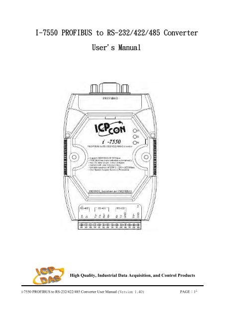
I-<strong>7550</strong> <strong>PROFIBUS</strong> <strong>to</strong> <strong>RS</strong>-<strong>232</strong>/<strong>422</strong>/<strong>485</strong> <strong>Converter</strong><br />
<strong>User's</strong> <strong>Manual</strong><br />
High Quality, Industrial Data Acquisition, and Control Products<br />
i-<strong>7550</strong> <strong>PROFIBUS</strong> <strong>to</strong> <strong>RS</strong>-<strong>232</strong>/<strong>422</strong>/<strong>485</strong> <strong>Converter</strong> User <strong>Manual</strong> (Version 1.40) PAGE:1
Warranty<br />
All products manufactured by ICP DAS are under warranty regarding<br />
defective materials for a period of one year from the date of delivery <strong>to</strong> the<br />
original purchaser.<br />
Warning<br />
ICP DAS assumes no liability for damages resulting from the use of<br />
this product. ICP DAS reserves the right <strong>to</strong> change this manual at any time<br />
without notice. The information furnished by ICP DAS is believed <strong>to</strong> be<br />
accurate and reliable. However, no responsibility is assumed by ICP DAS<br />
for its use, or for any infringements of patents or other right of third parties<br />
resulting from its use.<br />
Copyright<br />
Copyright by ICP DAS. All rights are reserved.<br />
Trademark<br />
The names used for identification only may be registered trademarks<br />
of their respective companies.<br />
List of Revision<br />
Date Author Version Revision<br />
2010/01/22 Raiden 1.40 Release<br />
i-<strong>7550</strong> <strong>PROFIBUS</strong> <strong>to</strong> <strong>RS</strong>-<strong>232</strong>/<strong>422</strong>/<strong>485</strong> <strong>Converter</strong> User <strong>Manual</strong> (Version 1.40) PAGE:2
Table of Contents<br />
1. Introduction…………………………………………………………... 4<br />
1.1 Features…………………………………………………………. 4<br />
1.2 Specification…………………………………………………….. 5<br />
2. Hardware……………………………………………………………... 6<br />
2.1 Block Diagram of the I-<strong>7550</strong>…………………………………… 6<br />
2.2 Pin Assignment…………………………………………………. 6<br />
2.3 Wiring and Jumper Setting Instructions………………………… 8<br />
2.4 Setting the <strong>PROFIBUS</strong> Address……………………………... 14<br />
2.5 LED status indica<strong>to</strong>r…………………………………………… 15<br />
3. Communication……………………………………………………... 17<br />
3.1 Field of application……………………………………………. 17<br />
3.2 Communication Sequence…………………………………….. 18<br />
3.3 I-<strong>7550</strong> in a <strong>RS</strong><strong>232</strong>/<strong>422</strong>/<strong>485</strong> network…………………………... 21<br />
3.4 <strong>PROFIBUS</strong> I/O Data Area…………………………………… 22<br />
3.5 Communication parameters…………………………………… 28<br />
3.6 Diagnostic messages……………………………………………37<br />
3.7 Establishing Connection with the I-<strong>7550</strong>……………………… 38<br />
4. Data Exchange Example……………………………………………. 41<br />
4.1 Configuration………………………………………………….. 41<br />
4.2 Communication Testing………………………………………. 45<br />
5. Troubleshooting…………………………………………………….. 53<br />
6. Dimensions…………………………………………………………. 54<br />
i-<strong>7550</strong> <strong>PROFIBUS</strong> <strong>to</strong> <strong>RS</strong>-<strong>232</strong>/<strong>422</strong>/<strong>485</strong> <strong>Converter</strong> User <strong>Manual</strong> (Version 1.40) PAGE:3
1. Introduction<br />
<strong>PROFIBUS</strong> is a field bus communication system with a wide range of applications,<br />
particularly in the fields of fac<strong>to</strong>ry and process au<strong>to</strong>mation. The I-<strong>7550</strong> integrates<br />
devices with serial <strong>RS</strong>-<strong>232</strong>, <strong>RS</strong>-<strong>485</strong> or <strong>RS</strong>-<strong>422</strong> interfaces in<strong>to</strong> a <strong>PROFIBUS</strong> DP<br />
network. Serial I/O devices, electronic scales, opera<strong>to</strong>r terminals, barcode readers and<br />
other au<strong>to</strong>mation devices can easily be connected <strong>to</strong> an existing <strong>PROFIBUS</strong> network.<br />
Figure 1 shows an application example for the I-<strong>7550</strong> module.<br />
Figure 1: Application architecture of the I-<strong>7550</strong> modules<br />
1.1 Features<br />
● 16-Bit Microprocessor inside with 80MHz<br />
● Siemens SPC3 <strong>PROFIBUS</strong> controller<br />
● Supports <strong>PROFIBUS</strong> DP-V0 slave<br />
● <strong>PROFIBUS</strong> transmission rate detect au<strong>to</strong>matically<br />
● Max transmission speed up <strong>to</strong> 12M bps for <strong>PROFIBUS</strong> and 115.2K bps for<br />
COM Port<br />
● COM Port driver has 100 KB QUEUE input buffer & 100 KB QUEUE output<br />
i-<strong>7550</strong> <strong>PROFIBUS</strong> <strong>to</strong> <strong>RS</strong>-<strong>232</strong>/<strong>422</strong>/<strong>485</strong> <strong>Converter</strong> User <strong>Manual</strong> (Version 1.40) PAGE:4
uffer<br />
● Max length of in/output data is 128 Bytes<br />
● Built-in self-tuner ASIC controller on <strong>RS</strong>-<strong>422</strong>/<strong>485</strong> port<br />
● 2500Vrms High Speed iCoupler Isolation Protection for <strong>PROFIBUS</strong> network<br />
● 3000VDC Isolation Protection on the <strong>PROFIBUS</strong> side<br />
● Provide LED indica<strong>to</strong>rs<br />
● Built-in Watchdog<br />
● Mountable on DIN Rail<br />
1.2 Specification<br />
COM Port specs:<br />
● Serial port - <strong>RS</strong>-<strong>232</strong>/<strong>RS</strong>-<strong>422</strong>/<strong>RS</strong>-<strong>485</strong><br />
● Serial port interface: 14-pin screw terminal block<br />
● Baud Rate:1200/2400/4800/9600/19200/38400/57600/115200 bps<br />
● Data Format: 7/8 data bits, None/Odd/Even parity bit, 1 s<strong>to</strong>p bit<br />
<strong>PROFIBUS</strong> specs:<br />
● <strong>PROFIBUS</strong> interface connec<strong>to</strong>r: D-sub 9-pin female<br />
● Baud Rate: 9.6K/19.2K/45.45K/93.75K/187.5K/500K/1.5M/3M/6M/ 12Mbps<br />
● Address Setting: 0~126 (set by DIP switch or EEPROM)<br />
Power requirement:<br />
● Unregulated +10V ~ +30V DC<br />
● Power reverse protection, Over-Voltage brown-out protection<br />
● Power consumption 2.5W<br />
Module specs:<br />
● Dimensions: 119mm X 72mm X 33mm<br />
● Operating temperature: -25 ~ 75 ºC<br />
● S<strong>to</strong>rage temperature: -30 ~ 85 ºC<br />
● Humidity:5 ~ 95%, non-condensing<br />
● LED Status Indica<strong>to</strong>rs (Table 1)<br />
Table 1: LED status indica<strong>to</strong>r<br />
− Shows the power state<br />
PWR LED<br />
− COM Port state: transmit or receive data<br />
ERR LED − Show error state<br />
RUN LED − Show communication state of <strong>PROFIBUS</strong><br />
i-<strong>7550</strong> <strong>PROFIBUS</strong> <strong>to</strong> <strong>RS</strong>-<strong>232</strong>/<strong>422</strong>/<strong>485</strong> <strong>Converter</strong> User <strong>Manual</strong> (Version 1.40) PAGE:5
2. Hardware<br />
2.1 Block Diagram of the I-<strong>7550</strong><br />
<strong>RS</strong>-<strong>485</strong><br />
DRIVE<br />
Figure 2: Block diagram of the I-<strong>7550</strong><br />
2.2 Pin Assignment<br />
Figure 3: Pin assignment of the I-<strong>7550</strong><br />
i-<strong>7550</strong> <strong>PROFIBUS</strong> <strong>to</strong> <strong>RS</strong>-<strong>232</strong>/<strong>422</strong>/<strong>485</strong> <strong>Converter</strong> User <strong>Manual</strong> (Version 1.40) PAGE:6
Table 2: 14-pin screw terminal block<br />
Pin Name Description<br />
1 D+ Data+ of <strong>RS</strong>-<strong>485</strong><br />
2 D- Data- of <strong>RS</strong>-<strong>485</strong><br />
3 - N/A<br />
4 TX+ Transmit Data+ of <strong>RS</strong>-<strong>422</strong><br />
5 TX- Transmit Data- of <strong>RS</strong>-<strong>422</strong><br />
6 RX+ Receive Data+ of <strong>RS</strong>-<strong>422</strong><br />
7 RX- Receive Data- of <strong>RS</strong>-<strong>422</strong><br />
8 - N/A<br />
9 RX Receive Data of <strong>RS</strong>-<strong>232</strong><br />
10 TX Transmit Data of <strong>RS</strong>-<strong>232</strong><br />
11 GND GND of <strong>RS</strong>-<strong>232</strong><br />
12 - N/A<br />
13 +VS V+ of Power Supply(+10 <strong>to</strong> +30VDC)<br />
14 GND GND of Power Supply<br />
Table 3: <strong>PROFIBUS</strong> DB9 Female Connec<strong>to</strong>r<br />
Pin Name Description<br />
1 - N/A<br />
2 - N/A<br />
3 B Non-inverting Bus Line<br />
4 ISODE Isolated DE output for use in <strong>PROFIBUS</strong><br />
applications where the state of the isolated drive<br />
enable node needs <strong>to</strong> be moni<strong>to</strong>red.<br />
5 GND Power supply ground for the first node and the last<br />
node<br />
6 VP +5V Power Supply for the first node and the last<br />
node<br />
7 - N/A<br />
8 A Inverting Bus Line<br />
9 - N/A<br />
i-<strong>7550</strong> <strong>PROFIBUS</strong> <strong>to</strong> <strong>RS</strong>-<strong>232</strong>/<strong>422</strong>/<strong>485</strong> <strong>Converter</strong> User <strong>Manual</strong> (Version 1.40) PAGE:7
2.3 Wiring and Jumper Setting Instructions<br />
The I-<strong>7550</strong> module supports <strong>PROFIBUS</strong> <strong>to</strong> Serial Port communication. It is<br />
recommended <strong>to</strong> use only one serial port (<strong>RS</strong><strong>232</strong>, <strong>RS</strong><strong>485</strong> or <strong>RS</strong><strong>422</strong>) of the converter<br />
at the same time. The following section describes the necessary steps <strong>to</strong> be taken <strong>to</strong><br />
connect one of the three COM port types <strong>to</strong> a serial device or serial network.<br />
2.3.1 <strong>RS</strong>-<strong>232</strong> Connection<br />
The <strong>RS</strong>-<strong>232</strong> port of the I-<strong>7550</strong> has got three pins. The wiring of the <strong>RS</strong>-<strong>232</strong><br />
device with the <strong>RS</strong><strong>232</strong> port of the I-<strong>7550</strong> is shown in Figure 4.<br />
i-<strong>7550</strong><br />
<strong>RS</strong>-<strong>232</strong> COM port<br />
<strong>RS</strong>-<strong>232</strong> device<br />
Figure 4: <strong>RS</strong>-<strong>232</strong> wiring diagram<br />
2.3.2 <strong>RS</strong>-<strong>422</strong> Connection<br />
The <strong>RS</strong>-<strong>422</strong> wiring connection is shown in Figure 5.<br />
The I-<strong>7550</strong> converter is always a <strong>PROFIBUS</strong> slave but it can in a local <strong>RS</strong>-<strong>422</strong><br />
network either take the position of a master or that of a slave. Depending on<br />
whether the converter acts as a local master or as a slave and on the number of<br />
devices connected <strong>to</strong> the <strong>RS</strong>-<strong>422</strong> network device the four jumpers provided by<br />
the module has <strong>to</strong> be set according <strong>to</strong> Table 4. The jumpers set the pull high and<br />
pull down resis<strong>to</strong>rs for the <strong>RS</strong>-<strong>422</strong> port (Figure 6, Figure 7).<br />
i-<strong>7550</strong> <strong>PROFIBUS</strong> <strong>to</strong> <strong>RS</strong>-<strong>232</strong>/<strong>422</strong>/<strong>485</strong> <strong>Converter</strong> User <strong>Manual</strong> (Version 1.40) PAGE:8
i-<strong>7550</strong><br />
<strong>RS</strong>-<strong>422</strong> port<br />
<strong>RS</strong>-<strong>422</strong> device<br />
Figure 5: <strong>RS</strong>-<strong>422</strong> connection<br />
Table 4: Jumper position for the <strong>RS</strong>-<strong>422</strong> port<br />
Pull high/low resis<strong>to</strong>r<br />
Enabled<br />
(default)<br />
Condition<br />
− The I-<strong>7550</strong> is the master in <strong>RS</strong>-<strong>422</strong><br />
bus or<br />
− the number of devices connected <strong>to</strong><br />
the <strong>RS</strong>-<strong>422</strong> bus is less than 10<br />
Disabled<br />
− The I-<strong>7550</strong> is a slave in <strong>RS</strong>-<strong>422</strong> bus<br />
or<br />
− the number of devices connected <strong>to</strong><br />
the <strong>RS</strong>-<strong>422</strong> bus exceeds 10<br />
i-<strong>7550</strong> <strong>PROFIBUS</strong> <strong>to</strong> <strong>RS</strong>-<strong>232</strong>/<strong>422</strong>/<strong>485</strong> <strong>Converter</strong> User <strong>Manual</strong> (Version 1.40) PAGE:9
Figure 6: Configuration of pull high/low resis<strong>to</strong>r for the <strong>RS</strong>-<strong>422</strong> port<br />
Figure 7: The positions of pull high/low resis<strong>to</strong>rs in I-<strong>7550</strong> module<br />
2.3.3 <strong>RS</strong>-<strong>485</strong> Connection<br />
The <strong>RS</strong>-<strong>485</strong> wiring diagram is shown in Figure 8.<br />
The I-<strong>7550</strong> converter can only act in the <strong>PROFIBUS</strong> network as a slave. In a <strong>RS</strong>-<br />
i-<strong>7550</strong> <strong>PROFIBUS</strong> <strong>to</strong> <strong>RS</strong>-<strong>232</strong>/<strong>422</strong>/<strong>485</strong> <strong>Converter</strong> User <strong>Manual</strong> (Version 1.40) PAGE:10
<strong>485</strong> network however it can either be a local master or slave. Before the module<br />
is connected <strong>to</strong> a <strong>RS</strong>-<strong>485</strong> network it is important <strong>to</strong> know whether the module<br />
takes the place of a slave or master and how many devices are active on the <strong>RS</strong>-<br />
<strong>485</strong> bus. The two jumpers (JP1 and JP2) have <strong>to</strong> be set according the bus<br />
configuration (Table 5).<br />
The jumpers set the pull high and pull down resis<strong>to</strong>rs for the <strong>RS</strong>-<strong>485</strong> port (Figure 9).<br />
i-<strong>7550</strong><br />
<strong>RS</strong>-<strong>485</strong> Port<br />
<strong>RS</strong>-<strong>485</strong> Device(s)<br />
Figure 8: <strong>RS</strong>-<strong>485</strong> connection<br />
Table 5: Jumper position for the <strong>RS</strong>-<strong>485</strong> port<br />
Pull high/low resis<strong>to</strong>r<br />
Enabled<br />
(default)<br />
Condition<br />
− The I-<strong>7550</strong> is the master in <strong>RS</strong>-<strong>485</strong><br />
bus or<br />
− the number of devices connected<br />
<strong>to</strong> the <strong>RS</strong>-<strong>485</strong> bus is less than 10<br />
Disabled<br />
− The I-<strong>7550</strong> is a slave in <strong>RS</strong>-<strong>485</strong><br />
bus or<br />
− the number of devices connected<br />
<strong>to</strong> the <strong>RS</strong>-<strong>485</strong> bus exceeds 10<br />
i-<strong>7550</strong> <strong>PROFIBUS</strong> <strong>to</strong> <strong>RS</strong>-<strong>232</strong>/<strong>422</strong>/<strong>485</strong> <strong>Converter</strong> User <strong>Manual</strong> (Version 1.40) PAGE:11
Figure 9: Configuration of pull high/low resis<strong>to</strong>r for the <strong>RS</strong>-<strong>485</strong> port<br />
2.3.4 <strong>PROFIBUS</strong> Connection<br />
The <strong>PROFIBUS</strong> interface of the I-<strong>7550</strong> is a DB9 female connec<strong>to</strong>r. The<br />
connec<strong>to</strong>r uses the standard <strong>PROFIBUS</strong> 9 pin assignment. It is recommended <strong>to</strong><br />
use a standard <strong>PROFIBUS</strong> cable and connec<strong>to</strong>r (DB9 male). As with every serial<br />
bus the rate of safe data transmission in a <strong>PROFIBUS</strong> network decreases with<br />
increasing distance between master and slave. Table 6 shows the transmission<br />
rate and range for a cable with the following properties:<br />
1. Impedance :135~165Ω<br />
2. Capacity : lower than 30 pF/m<br />
3. Loop resistance : lower than 110Ω/Km<br />
4. Wire diameter : greater than 0.65mm<br />
5. Core cross-section : greater than 0.34mm 2<br />
Table 6: Transmission rate decreasing with increasing transmission distance<br />
Transmission Rate(Kbps) Transmission Distance per Segment (meter)<br />
9.6; 19.2; 93.75 1200<br />
187.5 1000<br />
500 400<br />
1500 200<br />
3000; 6000; 12000 100<br />
i-<strong>7550</strong> <strong>PROFIBUS</strong> <strong>to</strong> <strong>RS</strong>-<strong>232</strong>/<strong>422</strong>/<strong>485</strong> <strong>Converter</strong> User <strong>Manual</strong> (Version 1.40) PAGE:12
In order <strong>to</strong> minimize the reflection effect of signal transmission, both ends (first<br />
node and last node) of a <strong>PROFIBUS</strong> segment needs <strong>to</strong> be equipped with an<br />
active terminal resis<strong>to</strong>r as shown in Figure 10. A standard <strong>PROFIBUS</strong> connec<strong>to</strong>r<br />
is usually already equipped with a terminal resis<strong>to</strong>r. The user therefore only has<br />
<strong>to</strong> switch on the resis<strong>to</strong>r of the devices stationed at the ends of a segment as<br />
shown in Figure 11.<br />
Figure 10: <strong>PROFIBUS</strong> connection<br />
Termina<strong>to</strong>r ON<br />
Termina<strong>to</strong>r OFF<br />
Termina<strong>to</strong>r Switch<br />
Figure 11: <strong>PROFIBUS</strong> connec<strong>to</strong>r<br />
i-<strong>7550</strong> <strong>PROFIBUS</strong> <strong>to</strong> <strong>RS</strong>-<strong>232</strong>/<strong>422</strong>/<strong>485</strong> <strong>Converter</strong> User <strong>Manual</strong> (Version 1.40) PAGE:13
The number of stations in a <strong>PROFIBUS</strong> network is restricted <strong>to</strong> 126. According<br />
<strong>to</strong> the <strong>PROFIBUS</strong> specification up <strong>to</strong> 32 stations are allowed per segment. A<br />
repeater has <strong>to</strong> be used <strong>to</strong> link the bus segments.<br />
2.4 Setting the <strong>PROFIBUS</strong> Address<br />
The station address of I-<strong>7550</strong> can be set by using either the dip switch or by<br />
writing it directly <strong>to</strong> the EEPROM. The dip switch covers a range from 0 <strong>to</strong> 255.<br />
The valid address range of a <strong>PROFIBUS</strong> station spans from 0 <strong>to</strong> 126. Table 7<br />
shows three examples of setting the station address by using the dip switch. The<br />
dip switches are accessed by opening the modules housing, Figure 12. Table 8<br />
explains which address will be used by the module after power on, if the dip<br />
switch address setting differs from the address s<strong>to</strong>red in the EEPROM.<br />
Table 7: Dip switch setting example<br />
Station address<br />
DIP SWITCH(SW1)<br />
1 2 3 4 5 6 7 8<br />
1 1 0 0 0 0 0 0 0<br />
10 0 1 0 1 0 0 0 0<br />
126 0 1 1 1 1 1 1 0<br />
Table 8: The Address setting of the I-<strong>7550</strong><br />
Dip Switch Setting<br />
0~125<br />
126-254<br />
Description<br />
1. The address setting of the EEPROM is<br />
ignored.<br />
2. The address can not be set by the <strong>PROFIBUS</strong><br />
configuration <strong>to</strong>ol.<br />
1. The address setting of the dip switch is<br />
ignored.<br />
2. If the address in the EEPROM is 126, the<br />
<strong>PROFIBUS</strong> configuration <strong>to</strong>ol can set a new<br />
address and save it <strong>to</strong> the EEPROM.<br />
255 1. Slave address in the EEPROM is set <strong>to</strong> 126.<br />
i-<strong>7550</strong> <strong>PROFIBUS</strong> <strong>to</strong> <strong>RS</strong>-<strong>232</strong>/<strong>422</strong>/<strong>485</strong> <strong>Converter</strong> User <strong>Manual</strong> (Version 1.40) PAGE:14
Figure 12: DIP switch<br />
Each slave must have a unique valid address (1 <strong>to</strong> 125) in order <strong>to</strong> be able <strong>to</strong><br />
communicate with the master. To change the address by using the configuration<br />
<strong>to</strong>ol it is necessary <strong>to</strong> first set the address s<strong>to</strong>red in the EEPROM <strong>to</strong> 126. This is<br />
done by setting the dip switch <strong>to</strong> 255 in the power off state. Switching the<br />
module on is forcing the module <strong>to</strong> change its address in the EEROM <strong>to</strong> 126. In<br />
the next step switch the module off and change the dip switch setting <strong>to</strong> any<br />
value from 126 <strong>to</strong> 254. This step is necessary in order <strong>to</strong> prevent the module <strong>to</strong><br />
change its address in the EEPROM <strong>to</strong> 126 every time it is powered on. The<br />
configuration <strong>to</strong>ol can now assign the slave a new address.<br />
2.5 LED status indica<strong>to</strong>r<br />
The I-<strong>7550</strong> provides three LEDs <strong>to</strong> indicate the statuses of the I-<strong>7550</strong> module.<br />
The position of LEDs and descriptions are shown in Table 9 and Figure 13.<br />
Table 9: LED status description<br />
LED Name Status Description<br />
PWR<br />
flash<br />
on<br />
off<br />
Power supply is ok.<br />
COM Port is transmitting or receiving data.<br />
Power supply is ok.<br />
The firmware has loaded.<br />
Power supply has failed.<br />
i-<strong>7550</strong> <strong>PROFIBUS</strong> <strong>to</strong> <strong>RS</strong>-<strong>232</strong>/<strong>422</strong>/<strong>485</strong> <strong>Converter</strong> User <strong>Manual</strong> (Version 1.40) PAGE:15
LED Name Status Description<br />
ERR<br />
RUN<br />
flash<br />
on<br />
off<br />
on<br />
off<br />
Error! I-<strong>7550</strong> has diagnostic message.<br />
− Connection error between <strong>PROFIBUS</strong> master and<br />
slave or<br />
− <strong>PROFIBUS</strong> system has not been configured<br />
correctly.<br />
Normal operation<br />
<strong>PROFIBUS</strong> system has been configured correctly<br />
Data exchange mode<br />
Normal operation.<br />
I-<strong>7550</strong> module is not in a data exchange mode.<br />
Figure 13: LED position<br />
i-<strong>7550</strong> <strong>PROFIBUS</strong> <strong>to</strong> <strong>RS</strong>-<strong>232</strong>/<strong>422</strong>/<strong>485</strong> <strong>Converter</strong> User <strong>Manual</strong> (Version 1.40) PAGE:16
3. Communication<br />
3.1 Field of application<br />
A master station can be a PLC, PC or any other smart device. The system can be<br />
a mono-master system (Figure 14) or a multi-master system (Figure 15). The I-<br />
<strong>7550</strong> enables the integration of single serial devices such as I/O devices,<br />
electronic scales, opera<strong>to</strong>r terminals, barcode readers and other au<strong>to</strong>mation<br />
devices which has a <strong>RS</strong>-<strong>232</strong>/<strong>RS</strong>-<strong>485</strong>/<strong>RS</strong>-<strong>422</strong> interface in<strong>to</strong> a <strong>PROFIBUS</strong> DP<br />
network.<br />
Figure 14: Mono-master system<br />
i-<strong>7550</strong> <strong>PROFIBUS</strong> <strong>to</strong> <strong>RS</strong>-<strong>232</strong>/<strong>422</strong>/<strong>485</strong> <strong>Converter</strong> User <strong>Manual</strong> (Version 1.40) PAGE:17
Figure 15: Multi-master system<br />
3.2 Communication Sequence<br />
To fully understand the I-<strong>7550</strong> field of applications, its strength and limitation it<br />
is important <strong>to</strong> understand the way in which data is processed by the converter.<br />
Basically the converter has got four buffers (Figure 16):<br />
− <strong>PROFIBUS</strong> slave input buffer<br />
− <strong>PROFIBUS</strong> slave output buffer<br />
− COM port input buffer<br />
− COM port output buffer<br />
The <strong>PROFIBUS</strong> master has basically got two buffers (Figure 17):<br />
− <strong>PROFIBUS</strong> master input buffer<br />
− <strong>PROFIBUS</strong> master output buffer<br />
During each message cycle the master writes the content of its output buffer <strong>to</strong><br />
the slaves input buffer and reads the content of the slave output buffer <strong>to</strong> its input<br />
buffer. This data exchange cycle is taken place in a regular time interval and<br />
i-<strong>7550</strong> <strong>PROFIBUS</strong> <strong>to</strong> <strong>RS</strong>-<strong>232</strong>/<strong>422</strong>/<strong>485</strong> <strong>Converter</strong> User <strong>Manual</strong> (Version 1.40) PAGE:18
irrespective of the converters COM port communication. This data exchange<br />
cycle in a fixed time interval is a distinctive feature of a <strong>PROFIBUS</strong> network.<br />
The exchange cycle is taking place even though the content of the master and<br />
slave output buffer has not changed.<br />
The way data is transferred from the COM port input buffer <strong>to</strong> the <strong>PROFIBUS</strong><br />
slave output buffer and from the <strong>PROFIBUS</strong> slave input buffer <strong>to</strong> COM port<br />
output buffer has <strong>to</strong> be configured by the <strong>PROFIBUS</strong> configuration program.<br />
i-<strong>7550</strong> <strong>PROFIBUS</strong> <strong>to</strong> Serial <strong>Converter</strong>:<br />
<strong>PROFIBUS</strong> Network<br />
<strong>PROFIBUS</strong><br />
:<br />
Output<br />
Buffer<br />
Input<br />
Buffer<br />
Micro<br />
processor<br />
Serial:<br />
Input<br />
Buffer<br />
Output<br />
Buffer<br />
Serial Network<br />
Figure 16: Data flow in the converter<br />
Before a cyclic communication between a <strong>PROFIBUS</strong> master and the converter<br />
can be established it is required <strong>to</strong> specify the number of input and output bytes<br />
that are <strong>to</strong> be exchanged in each telegram cycle with the <strong>PROFIBUS</strong><br />
configuration program. Once the slave is an active station in the <strong>PROFIBUS</strong><br />
network the configured input and output length can not be changed. A new<br />
configuration of the slave is only possible when it is in an off-line mode.<br />
If for example the converter receives from a <strong>RS</strong><strong>232</strong> device a greater data package<br />
than the configured output length it will only transfer the configured data length<br />
<strong>to</strong> the <strong>PROFIBUS</strong> master. The remaining data packet will not be sent. That<br />
means irrelevant of the amount of data received by the I-<strong>7550</strong> converter the data<br />
length transmitted <strong>to</strong> the <strong>PROFIBUS</strong> master is always limited by configured<br />
length.<br />
i-<strong>7550</strong> <strong>PROFIBUS</strong> <strong>to</strong> <strong>RS</strong>-<strong>232</strong>/<strong>422</strong>/<strong>485</strong> <strong>Converter</strong> User <strong>Manual</strong> (Version 1.40) PAGE:19
3.2.1 Data Flow<br />
3.2.1.1 <strong>PROFIBUS</strong> master send output <strong>to</strong> the serial COM port<br />
The master sends in a fixed time interval data from its master output buffer<br />
<strong>to</strong> the slave input buffer (Figure 17). The master does not care whether the<br />
data has already been send or not. It only reads data from its output buffer<br />
and does not remove the data from the output buffer after it has been send.<br />
If data in the masters input buffer does not change between two message<br />
cycles the master will send the same data, which has been transferred in the<br />
previously cycle, again <strong>to</strong> the slave.<br />
Therefore an information string is attached by the master application<br />
program at the front of each message which enables the I-<strong>7550</strong> converter <strong>to</strong><br />
check whether it has already been dispatched <strong>to</strong> the COM port or not. In<br />
case of new data it is immediately sent via the serial output buffer <strong>to</strong> the<br />
COM port.<br />
3.2.1.2 <strong>PROFIBUS</strong> master reads input data arriving at the serial<br />
COM port<br />
The master sends and reads data in one telegram cycle (Figure 17). The<br />
telegram cycle starts at a configured time interval regardless whether new<br />
data has arrived or not. That means the master reads data from the I-<strong>7550</strong><br />
<strong>PROFIBUS</strong> output buffer not knowing whether it has already been read in<br />
the previous cycle. It therefore necessary <strong>to</strong> reserve part of the master input<br />
string for the message status information.<br />
Data arriving at the COM port enters the serial input buffer (Figure 16).<br />
This data is transferred <strong>to</strong> the <strong>PROFIBUS</strong> output buffer according <strong>to</strong> the<br />
setting done by the configuration program. Status information of this data<br />
package is added <strong>to</strong> the front of the string. Once data arrives at the I-<strong>7550</strong><br />
<strong>PROFIBUS</strong> output buffer the master can access this data in the next polling<br />
cycle. The master application program (Figure 17) recognizes a new data<br />
packet by interpreting the status information of each individual data packet.<br />
It is important <strong>to</strong> remember that the communication procedure between<br />
application program and master is independent of the telegram cycle<br />
between master and slave.<br />
i-<strong>7550</strong> <strong>PROFIBUS</strong> <strong>to</strong> <strong>RS</strong>-<strong>232</strong>/<strong>422</strong>/<strong>485</strong> <strong>Converter</strong> User <strong>Manual</strong> (Version 1.40) PAGE:20
Master Application<br />
Programm:<br />
Data is<br />
transferred on a<br />
program call<br />
Program sends<br />
data <strong>to</strong> the<br />
Master<br />
<strong>PROFIBUS</strong> Master:<br />
Input<br />
Buffer<br />
Output<br />
Buffer<br />
<strong>PROFIBUS</strong> Network<br />
Read<br />
Write<br />
i-<strong>7550</strong> <strong>PROFIBUS</strong><br />
Part:<br />
<strong>PROFIBUS</strong><br />
:<br />
Output<br />
Buffer<br />
Input<br />
Buffer<br />
Figure 17: Data flow between application program and converter<br />
3.3 I-<strong>7550</strong> in a <strong>RS</strong><strong>232</strong>/<strong>422</strong>/<strong>485</strong> network<br />
Chapter 0 mentions that the converter can either take the position of a local<br />
master or that of a slave in the serial network (Figure 18) it is connected <strong>to</strong>. In<br />
the <strong>PROFIBUS</strong> network the I-<strong>7550</strong> always remains a slave <strong>PROFIBUS</strong> slave and<br />
can not be used as a <strong>PROFIBUS</strong> master.<br />
3.3.1 Local Serial Master<br />
A master in a serial network is the only device which can initiate a request. The<br />
slaves are passive and are only allowed <strong>to</strong> response <strong>to</strong> a request. If the<br />
converter acts as a master in the serial network it has the right <strong>to</strong> send a request<br />
<strong>to</strong> a slave. The original request has been send by the <strong>PROFIBUS</strong> master<br />
application program and the converter just passes it on. The <strong>PROFIBUS</strong> master<br />
application program therefore acts as a master <strong>to</strong> the local serial network. The<br />
response from the slave is transferred <strong>to</strong> the <strong>PROFIBUS</strong> output buffer of the<br />
converter. In the following polling cycle the <strong>PROFIBUS</strong> master reads the<br />
response data.<br />
3.3.2 Local Serial Slave<br />
In this case the converter is the passive device in the serial network and is only<br />
allowed <strong>to</strong> send data when a request has been specifically addressed <strong>to</strong> it. As<br />
this converter can not be assigned an address, every message transferred in the<br />
i-<strong>7550</strong> <strong>PROFIBUS</strong> <strong>to</strong> <strong>RS</strong>-<strong>232</strong>/<strong>422</strong>/<strong>485</strong> <strong>Converter</strong> User <strong>Manual</strong> (Version 1.40) PAGE:21
local serial network will be read by the converter and forwarded <strong>to</strong> the<br />
<strong>PROFIBUS</strong> master. It is the master application program which has <strong>to</strong> process<br />
the data and take the place of a serial slave. The master application program<br />
acting as a slave therefore should only response <strong>to</strong> telegram addressed <strong>to</strong> it.<br />
Notice:<br />
All the data transfer in the serial network is recorded by the module and<br />
consequently read by the <strong>PROFIBUS</strong> master.<br />
PLC<br />
<strong>PROFIBUS</strong> DP<br />
i-<strong>7550</strong><br />
<strong>PROFIBUS</strong><br />
slave<br />
<strong>RS</strong><strong>422</strong> or <strong>RS</strong><strong>485</strong> network<br />
Figure 18: Integrating a serial network <strong>to</strong> a <strong>PROFIBUS</strong> network<br />
3.4 <strong>PROFIBUS</strong> I/O Data Area<br />
The <strong>PROFIBUS</strong> master sends and receives data in one telegram cycle. That is,<br />
the master sends output data <strong>to</strong> the slave (I-<strong>7550</strong> module) and receives input data<br />
from the slave in a single cycle. The maximum length for each input and output<br />
data is 128 bytes.<br />
i-<strong>7550</strong> <strong>PROFIBUS</strong> <strong>to</strong> <strong>RS</strong>-<strong>232</strong>/<strong>422</strong>/<strong>485</strong> <strong>Converter</strong> User <strong>Manual</strong> (Version 1.40) PAGE:22
3.4.1 Input Data Area<br />
The first four bytes of the received input data are reserved for the<br />
communication status.<br />
The first byte indicates the transmission status. The second byte shows the<br />
error state. The third byte shows the length of the data transferred from the<br />
COM port input buffer <strong>to</strong> the <strong>PROFIBUS</strong> output buffer of the converter. The<br />
fourth byte represents a transmission counter.<br />
The remaining data in the input data area represents the data packet received<br />
from the serial network. The fifth byte therefore shows the first byte of the<br />
received serial data.<br />
Table 10: Input data area<br />
Byte Data Description<br />
0x00<br />
I-<strong>7550</strong> is currently not transmitting I/O data<br />
Message<br />
property<br />
1<br />
2<br />
0x01<br />
0x02<br />
Error<br />
State<br />
I-<strong>7550</strong> is transmitting data <strong>to</strong> the COM Port<br />
I-<strong>7550</strong> is receiving data :<br />
Data received by the COM Port input buffer is<br />
transferred <strong>to</strong> the <strong>PROFIBUS</strong> output buffer<br />
Bit 1: Output FIFO overflow<br />
Bit 2 : Input FIFO overflow<br />
Bit 3 : Output data loss<br />
Bit 4 : Input data loss<br />
3 Length Received data length<br />
4 Counter Received data count<br />
Input<br />
Data<br />
5~128 Data Receive data from COM Port<br />
Data Length (3. byte):<br />
It is important <strong>to</strong> notice that this value does not show the length of the data<br />
package read by the <strong>PROFIBUS</strong> master but the length of the data package<br />
transferred from the COM port input buffer <strong>to</strong> the <strong>PROFIBUS</strong> output buffer of<br />
the converter. If the image of the input data (<strong>PROFIBUS</strong> master input length)<br />
set by the configuration <strong>to</strong>ol is equal or greater than the transferred length then<br />
the length of both data packages are identical. In case the image of the input<br />
data is smaller than the length of the data package transferred from the COM<br />
port input buffer then the <strong>PROFIBUS</strong> master will only read the number of<br />
bytes set by the configuration <strong>to</strong>ol. The master therefore does not receive all<br />
i-<strong>7550</strong> <strong>PROFIBUS</strong> <strong>to</strong> <strong>RS</strong>-<strong>232</strong>/<strong>422</strong>/<strong>485</strong> <strong>Converter</strong> User <strong>Manual</strong> (Version 1.40) PAGE:23
the data sent by the serial network. It lies in the responsibility of the system<br />
administra<strong>to</strong>r <strong>to</strong> make sure that the input image is set <strong>to</strong> the maximum possible<br />
number of bytes the serial network is going <strong>to</strong> respond.<br />
Transmission Counter (4. byte):<br />
For every data string transferred from the COM port input buffer <strong>to</strong> the<br />
<strong>PROFIBUS</strong> output buffer the counter is incremented by one.<br />
After the master has read the data from the I-<strong>7550</strong> <strong>PROFIBUS</strong> output buffer<br />
(Figure 19) the content of this buffer remains unchanged until a new data<br />
packet is copied from the COM port input buffer. Therefore if no new data<br />
arrives at the COM input buffer the <strong>PROFIBUS</strong> master will always read the<br />
same data package. The master application program has <strong>to</strong> check the Counter<br />
(Byte 3) <strong>to</strong> ensure that the data read is new.<br />
In case for example the connection between the converter and the serial<br />
network breaks or the connected serial device has a break down then no new<br />
data arrives at the converter. The Master will still continue reading the data<br />
package sent before the technical failure occurred. To prevent a<br />
misinterpretation of the data it is necessary <strong>to</strong> check the counter.<br />
i-<strong>7550</strong> <strong>PROFIBUS</strong> <strong>to</strong> Serial <strong>Converter</strong>:<br />
<strong>PROFIBUS</strong> Network<br />
<strong>PROFIBUS</strong><br />
:<br />
Output<br />
Buffer<br />
Micro<br />
processor<br />
Serial/COM:<br />
Input<br />
Buffer<br />
Serial Network<br />
Figure 19: Data flow from the serial bus <strong>to</strong> the <strong>PROFIBUS</strong> network<br />
i-<strong>7550</strong> <strong>PROFIBUS</strong> <strong>to</strong> <strong>RS</strong>-<strong>232</strong>/<strong>422</strong>/<strong>485</strong> <strong>Converter</strong> User <strong>Manual</strong> (Version 1.40) PAGE:24
3.4.2 Output Data Area<br />
The maximum length of output data is 128 bytes. The first six bytes are needed<br />
<strong>to</strong> set the communication behavior of the converter.<br />
Table 11: Output data area<br />
Byte<br />
1<br />
Bit Position<br />
7 6 5 4 3 2 1 0<br />
Description<br />
Data output command<br />
(Required for every output command)<br />
2 - - - - - - CC DC Control bit<br />
COM port<br />
sending<br />
behavior<br />
3<br />
4<br />
Output data length<br />
(Default value is zero.<br />
Necessary for every output command)<br />
Interval time between the two<br />
batches of the data (Default value<br />
is zero.)<br />
COM port<br />
receiving<br />
behavior<br />
Output<br />
Data<br />
5 Timeout value<br />
6 Fixed data length<br />
7~128 Output data <strong>to</strong> COM Port<br />
Data output command (1. Byte):<br />
The <strong>PROFIBUS</strong> master is cyclically polling the I-<strong>7550</strong> module. In a cycle the<br />
master sends data from its output buffer <strong>to</strong> the input buffer of the converter and<br />
in the same cycle reads data from the output buffer of the converter. If no new<br />
data is put on the master output buffer the master sends in each polling cycle<br />
the same data. It is therefore necessary for the converter <strong>to</strong> detect whether the<br />
data arriving at its <strong>PROFIBUS</strong> input buffer has already been sent before or is<br />
new. The converter recognizes a new data packet when the value of the first<br />
byte differs from the previous data packet. A change of the first byte results in<br />
an immediate output of the newly arrived data (at the <strong>PROFIBUS</strong> input buffer)<br />
<strong>to</strong> the serial COM port. When the user wants <strong>to</strong> send a new data packet <strong>to</strong> the<br />
converter, the user should increase progressively the first byte (ex: 0->1, 1->2,<br />
2->3, …, 255->0) and the converter will send the new data packet <strong>to</strong> the serial<br />
COM port. If the user changes the first byte but doesn’t increase progressively<br />
i-<strong>7550</strong> <strong>PROFIBUS</strong> <strong>to</strong> <strong>RS</strong>-<strong>232</strong>/<strong>422</strong>/<strong>485</strong> <strong>Converter</strong> User <strong>Manual</strong> (Version 1.40) PAGE:25
it (ex: 0->2, 1->3, 2->5), the converter will send a diagnostic message <strong>to</strong> show<br />
“Output data loss” <strong>to</strong> <strong>PROFIBUS</strong> Master. The user can know the <strong>PROFIBUS</strong><br />
data may be loss by this message.<br />
Note:<br />
The converter will send no data <strong>to</strong> the connected serial devices if the content of<br />
the first byte of two consecutive <strong>PROFIBUS</strong> messages is identical. Even if the<br />
remaining bytes differ, no message will be forwarded <strong>to</strong> the COM port. The<br />
converter detects a new data packet only by checking the first byte.<br />
Control bit (2. byte)<br />
− DC: When this bit is set (DC=1), diagnostic messages send by the I-<strong>7550</strong><br />
module will all be cleared.<br />
− CC: When this bit is set (CC=1) the I-<strong>7550</strong> module sets the “Receive data<br />
count” (fourth byte of the input data area, Table 10) <strong>to</strong> zero.<br />
− Bit 2~7: The remaining bits have <strong>to</strong> be set <strong>to</strong> zero.<br />
Output data length (3. byte)<br />
The output data length default value is zero. It has <strong>to</strong> be set for every single<br />
output command otherwise no data will be send <strong>to</strong> the COM port.<br />
This byte determines the number of bytes copied from the I-<strong>7550</strong> <strong>PROFIBUS</strong><br />
input buffer <strong>to</strong> the COM output buffer. That means independent of the data<br />
length send by the master only the number of bytes specified in the third byte<br />
will be forwarded <strong>to</strong> the COM port.<br />
There is a restriction <strong>to</strong> this: With the <strong>PROFIBUS</strong> configuration program the<br />
number of input and output bytes that are <strong>to</strong> be exchanged in each telegram<br />
cycle with the slave is specified. These numbers of input and output bytes are<br />
fixed and can not be altered when the master is active. In each telegram cycle<br />
these set number of input and output bytes are exchanged independently of the<br />
length entered in the “Output data length” (3. byte).<br />
Imagine the data output and input length as output and input containers. The<br />
<strong>PROFIBUS</strong> configuration program allows you <strong>to</strong> set the size in bytes of the<br />
output and input container. During each poll cycle the output container is send<br />
<strong>to</strong> the converter irrelevant whether the container has been filled or only partly<br />
filled with new data. The same procedure applies <strong>to</strong> input container which is<br />
send off by the converter.<br />
Case1: Normal operation<br />
“Output data length” is smaller than or equal <strong>to</strong> the size of the output container:<br />
i-<strong>7550</strong> <strong>PROFIBUS</strong> <strong>to</strong> <strong>RS</strong>-<strong>232</strong>/<strong>422</strong>/<strong>485</strong> <strong>Converter</strong> User <strong>Manual</strong> (Version 1.40) PAGE:26
Only the data string specified by the “Output data length” is send <strong>to</strong> the serial<br />
network.<br />
Case 2:<br />
“Output data length” is greater than the output container size:<br />
The data package dispatched by the COM port equals <strong>to</strong> the data inside the<br />
output container.<br />
Case 3:<br />
The <strong>PROFIBUS</strong> master application program sends less data <strong>to</strong> the output<br />
container than it can hold. This means that only part of the data in the output<br />
container is overwritten by new data but the container still holds data from<br />
previous message which has not been overwritten. The container with the new<br />
and old data is being sent off <strong>to</strong> the I-<strong>7550</strong> module. If the “Output data length”<br />
is greater than the new data then new data <strong>to</strong>gether with old invalid data will be<br />
dispatched at the COM port.<br />
Interval time (4. byte)<br />
This byte can increase the interval time between the two batches of the data<br />
packet, It means the converter can delay the data output from <strong>PROFIBUS</strong> <strong>to</strong><br />
Series COM port.<br />
Figure 20: Interval time application<br />
i-<strong>7550</strong> <strong>PROFIBUS</strong> <strong>to</strong> <strong>RS</strong>-<strong>232</strong>/<strong>422</strong>/<strong>485</strong> <strong>Converter</strong> User <strong>Manual</strong> (Version 1.40) PAGE:27
Timeout value (5. byte)<br />
The timeout is only relevant for the communication between the I-<strong>7550</strong><br />
converter and the serial network. The converter receives the response of a<br />
device in the serial network at the COM port as a continuous data stream. A<br />
silent interval in the data stream exceeding the timeout value signals the<br />
converter the end of the message and forwards this message <strong>to</strong> its <strong>PROFIBUS</strong><br />
output buffer.<br />
Valid values for the timeout: 0 <strong>to</strong> 255<br />
A “0” represents the minimum value which equals the transmission time of one<br />
byte [(start bit+data bit+parity bit+s<strong>to</strong>p bit)/Baudrate]. A “1” assigns a timeout<br />
value of either 1 or 10 milliseconds depending on the chosen unit (1 or 10ms).<br />
The maximum value “255” represents either 255 milliseconds (time unit: 1ms)<br />
or 2550 milliseconds (time unit:10 ms).<br />
With this byte each output telegram send by the <strong>PROFIBUS</strong> master specifies<br />
the timeout for the data stream of the serial response. If for every request send<br />
by the converter multiply responses are expected, then the timeout applies <strong>to</strong><br />
all these messages.<br />
The timeout value is saved in a nonvolatile memory. After switching the<br />
converter on the timeout value from the last telegram send before it was<br />
switched off will be used for the COM port receive mode.<br />
Fixed data length (6.byte)<br />
This byte determines the length of the serial response data string. The<br />
converter waits until the data arriving at the COM port buffer has reached the<br />
specified length before it is copied <strong>to</strong> its <strong>PROFIBUS</strong> output buffer. In the next<br />
polling cycle of the <strong>PROFIBUS</strong> master this data is filled in<strong>to</strong> the input<br />
container and sent <strong>to</strong> the master.<br />
Notice:<br />
To use this feature the “Data length” mode has <strong>to</strong> be enabled by the<br />
<strong>PROFIBUS</strong> configuration <strong>to</strong>ol, otherwise this byte value will be ignored.<br />
3.5 Communication parameters<br />
In order for the converter <strong>to</strong> exchange data between a <strong>PROFIBUS</strong> network and a<br />
serial device or serial network, the<br />
− <strong>PROFIBUS</strong> communication parameters and<br />
− serial bus communication parameters<br />
have <strong>to</strong> be set by a <strong>PROFIBUS</strong> configuration program.<br />
i-<strong>7550</strong> <strong>PROFIBUS</strong> <strong>to</strong> <strong>RS</strong>-<strong>232</strong>/<strong>422</strong>/<strong>485</strong> <strong>Converter</strong> User <strong>Manual</strong> (Version 1.40) PAGE:28
PROFIB<br />
US<br />
Network<br />
PROFIB<br />
US<br />
I-<strong>7550</strong><br />
Serial bus<br />
<strong>RS</strong><strong>232</strong>/<strong>485</strong>/<strong>422</strong><br />
Serial<br />
Network<br />
Figure 21: The converter links the serial network <strong>to</strong> the <strong>PROFIBUS</strong> network<br />
3.5.1 <strong>PROFIBUS</strong> Communication Parameters<br />
Before communication can be establish a process image for the output and<br />
input data has <strong>to</strong> be set by the <strong>PROFIBUS</strong> configuration <strong>to</strong>ol. That is, the<br />
numbers of bytes send and received during a single data exchange cycle by the<br />
<strong>PROFIBUS</strong> master. Figuratively speaking the <strong>PROFIBUS</strong> master<br />
communicates with the slave by sending it a fixed size container filled with<br />
output data and receiving a fixed size container filled with input data. This<br />
configuration can not be changed during the bus operation. That means the size<br />
of the output and input container can not be changed while the converter is<br />
active on the bus. Modification of the setting is only possible when the<br />
communication between master and slave has s<strong>to</strong>pped.<br />
Steps <strong>to</strong> set the output and input data length:<br />
Step 1: Load the following GSD file and BMP file of the I-<strong>7550</strong> module in<strong>to</strong><br />
the <strong>PROFIBUS</strong> configuration <strong>to</strong>ol:<br />
IPDS0B0D.gsd<br />
ICP_<strong>7550</strong>.bmp<br />
i-<strong>7550</strong>.bmp<br />
(PATH-->CD: \<strong>PROFIBUS</strong>\ <strong>Converter</strong>\i-<strong>7550</strong>\GSD\)<br />
Step 2: Add the I-<strong>7550</strong> module as a slave <strong>to</strong> the configuration <strong>to</strong>ol<br />
Step 3: Assign the converter a unique station address<br />
Slave configuration:<br />
Step 4: Select “System setting” (Figure 22).<br />
i-<strong>7550</strong> <strong>PROFIBUS</strong> <strong>to</strong> <strong>RS</strong>-<strong>232</strong>/<strong>422</strong>/<strong>485</strong> <strong>Converter</strong> User <strong>Manual</strong> (Version 1.40) PAGE:29
Figure 22: “System setting” is right at the <strong>to</strong>p of the module list<br />
Step 5: Select the input length or in other words the size of the input container:<br />
Please make sure not <strong>to</strong> exceed the maximum input length of 128<br />
bytes.<br />
For example: “4 Byte In” represent a input length of four bytes.<br />
Step 6: Select the output length (size of the output container):<br />
The maximum output length is limited <strong>to</strong> 128 bytes.<br />
For example: “11 Byte Out”<br />
3.5.2 Serial Communication Parameters<br />
The converter can only establish a communication with the serial network, if<br />
the following parameters are identical for both the serial network and the I-<br />
<strong>7550</strong> COM port:<br />
− COM Port baud rate<br />
− COM Port parity<br />
− COM Port data length<br />
Table 12 shows the supported configuration setting.<br />
Table 12: COM port settings<br />
Description<br />
Parameter<br />
1200<br />
2400<br />
4800<br />
9600<br />
COM Port baud rate<br />
19200<br />
38400<br />
57600<br />
115200<br />
None<br />
COM Port parity Even<br />
Odd<br />
7 data bit<br />
COM Port data length<br />
8 data bit<br />
i-<strong>7550</strong> <strong>PROFIBUS</strong> <strong>to</strong> <strong>RS</strong>-<strong>232</strong>/<strong>422</strong>/<strong>485</strong> <strong>Converter</strong> User <strong>Manual</strong> (Version 1.40) PAGE:30
In addition for the converter <strong>to</strong> correctly read the end of the data string arriving<br />
from the serial network and make that data accessible <strong>to</strong> the <strong>PROFIBUS</strong><br />
network one of the following parameters (options) have <strong>to</strong> be set:<br />
− the end character or<br />
− the byte array length or<br />
− max time period between the arrival of the first byte and the last byte<br />
(time out)<br />
Table 13:<br />
Description<br />
End Character (s):<br />
(The end character of the<br />
receiving serial data)<br />
Data Length [Bytes]:<br />
(The length [in bytes] of<br />
the receiving serial data)<br />
Time Unit:<br />
(The unit for the Time Out<br />
value)<br />
Diagnosis of time out<br />
about input data<br />
Parameter<br />
None<br />
CR (Carriage Return)<br />
LF (line Feed)<br />
CR+LF<br />
LF+CR<br />
Disable<br />
Enable<br />
1ms<br />
10ms<br />
None<br />
Master Slave mode<br />
Cyclic input data mode<br />
The following description will only look at the data flow from the COM port <strong>to</strong><br />
the <strong>PROFIBUS</strong> port of the I-<strong>7550</strong> module (Figure 23):<br />
End Character (s)<br />
The “End Character (s)” can be set directly by the <strong>PROFIBUS</strong> configuration<br />
program. As soon as the converter detects the end characters of the incoming<br />
serial data stream it removes the data from the serial receive buffer and<br />
transfers it <strong>to</strong> the <strong>PROFIBUS</strong> output buffer of the converter. The <strong>PROFIBUS</strong><br />
master will read the new data string from the I-<strong>7550</strong> output buffer during the<br />
next send and request telegram.<br />
i-<strong>7550</strong> <strong>PROFIBUS</strong> <strong>to</strong> <strong>RS</strong>-<strong>232</strong>/<strong>422</strong>/<strong>485</strong> <strong>Converter</strong> User <strong>Manual</strong> (Version 1.40) PAGE:31
i-<strong>7550</strong> <strong>PROFIBUS</strong> <strong>to</strong> Serial <strong>Converter</strong>:<br />
<strong>PROFIBUS</strong> Network<br />
<strong>PROFIBUS</strong><br />
:<br />
Output<br />
Buffer<br />
Micro<br />
processor<br />
Serial/COM:<br />
Input<br />
Buffer<br />
Serial Network<br />
Figure 23: Data flow from the serial bus <strong>to</strong> the <strong>PROFIBUS</strong> network<br />
Example 1:<br />
The end character is set <strong>to</strong> CR (0x0D); see Figure 24<br />
Figure 24: The carriage return is set <strong>to</strong> determine the end of a data packet<br />
Stream arriving at the COM port:<br />
01 02 03 04 05 0D 06 07 08 09 0A 0D 0B 0C 0D<br />
Values are hex number<br />
Single data strings transferred from the serial input buffer <strong>to</strong> the <strong>PROFIBUS</strong><br />
output buffer:<br />
1. String:<br />
01 02 03 04 05<br />
2. String<br />
06 07 08 09 0A<br />
3. String<br />
0B 0C<br />
If the <strong>PROFIBUS</strong> network is configured in such a way that the time interval<br />
i-<strong>7550</strong> <strong>PROFIBUS</strong> <strong>to</strong> <strong>RS</strong>-<strong>232</strong>/<strong>422</strong>/<strong>485</strong> <strong>Converter</strong> User <strong>Manual</strong> (Version 1.40) PAGE:32
etween the cyclic sent and request Telegrams is larger than the time interval<br />
of data being send from the serial input buffer <strong>to</strong> the <strong>PROFIBUS</strong> output buffer<br />
than the data in the <strong>PROFIBUS</strong> output buffer will be overwritten by the next<br />
incoming data. In other words if the <strong>PROFIBUS</strong> master reads the data in the<br />
<strong>PROFIBUS</strong> output buffer at a slower speed than data is written <strong>to</strong> the buffer<br />
then data will get lost. Each new data string arriving from the serial input<br />
buffer will overwrite the previous data string in the <strong>PROFIBUS</strong> output buffer.<br />
Example 2:<br />
If the time interval between two consecutive bytes is longer than the time<br />
needed <strong>to</strong> transmit three bytes then the module treat this situation as an end of<br />
a string although the end character has not been send and sends the data <strong>to</strong> the<br />
<strong>PROFIBUS</strong> output buffer<br />
The end character is set <strong>to</strong> CR (0x0D)<br />
01 02 03 04 05 0D 01 02 03 04 05 0D<br />
Single data strings transferred <strong>to</strong> the serial input buffer <strong>to</strong> the<br />
output buffer:<br />
1. String:<br />
01 02 03<br />
2. String<br />
04 05<br />
3. String<br />
01 02 03 04 05<br />
<strong>PROFIBUS</strong><br />
Data Length [Bytes]:<br />
The converter counts the number of bytes arriving at the COM port. If the<br />
specified number of data length has entered the serial input buffer the content<br />
is removed from the input buffer and transferred <strong>to</strong> the <strong>PROFIBUS</strong> output<br />
buffer.<br />
Figure 25: Activating the data length mask<br />
The <strong>PROFIBUS</strong> configuration <strong>to</strong>ol allows you only <strong>to</strong> activate the counter<br />
i-<strong>7550</strong> <strong>PROFIBUS</strong> <strong>to</strong> <strong>RS</strong>-<strong>232</strong>/<strong>422</strong>/<strong>485</strong> <strong>Converter</strong> User <strong>Manual</strong> (Version 1.40) PAGE:33
(Figure 25) but not <strong>to</strong> enter the input data length. The data length has <strong>to</strong> be<br />
defined in the sixth byte of the output data send by the <strong>PROFIBUS</strong> Master. For<br />
each output data you can define the length of the response data. It is therefore<br />
possible <strong>to</strong> define in each request the length of the respective response. If the<br />
length for the response telegram has not been defined by the request telegram<br />
the length specified by the preceding telegram cycle will be used. Once the<br />
response data length has been specified the I-<strong>7550</strong> module will wait for the<br />
requested number of bytes <strong>to</strong> arrive at the COM port input buffer before the<br />
data string will be transferred <strong>to</strong> the <strong>PROFIBUS</strong> output buffer. In certain<br />
situation it may happen that the requested number of bytes are not received (e.g.<br />
due <strong>to</strong> data loss). To prevent the module <strong>to</strong> wait indefinitely for the remaining<br />
data the module au<strong>to</strong>matically recognize the end of a data stream after a time<br />
needed <strong>to</strong> transmit three bytes has elapsed. This time is dependent of the baud<br />
rate: the greater the baud rate the shorter is the transmitting time.<br />
Example 1:<br />
In the request telegram send by the <strong>PROFIBUS</strong> master the response length is<br />
set <strong>to</strong> 5 bytes.<br />
The Stream arriving at the COM port:<br />
01 02 03 04 05 06 07 08 09 0A 0B 0C<br />
Values are hex number<br />
Data strings transferred from the serial input buffer <strong>to</strong> the <strong>PROFIBUS</strong> output<br />
buffer:<br />
1. String:<br />
01 02 03 04 05<br />
2. String:<br />
06 07 08 09 0A<br />
3. String:<br />
0B 0C<br />
The <strong>PROFIBUS</strong> master receives the following data from the converter:<br />
1. String:<br />
00 05 01 01 02 03 04 05<br />
2. String:<br />
00 05 02 06 07 08 09 0A<br />
3. String:<br />
00 02 03 0B 0C<br />
According <strong>to</strong> Table 10 the first byte indicates the transmission state; the second<br />
byte shows the length of the incoming data; the third byte displays the value of<br />
the receiving counter of the incoming data package. The value of the third byte<br />
i-<strong>7550</strong> <strong>PROFIBUS</strong> <strong>to</strong> <strong>RS</strong>-<strong>232</strong>/<strong>422</strong>/<strong>485</strong> <strong>Converter</strong> User <strong>Manual</strong> (Version 1.40) PAGE:34
will increment by one with each data package transfer from the COM buffer <strong>to</strong><br />
the <strong>PROFIBUS</strong> output buffer of the converter.<br />
The third string will only be send after a transmit time of three bytes has<br />
elapsed. The module is waiting for 5 bytes but has only received two bytes.<br />
In this example the data string arrives most probably faster at <strong>PROFIBUS</strong><br />
output buffer of the converter than the master will be able <strong>to</strong> poll the data.<br />
Depending on the Baudrate and polling cycle the <strong>PROFIBUS</strong> master will<br />
receive in the worst case only the last string:<br />
3. String:<br />
00 02 03 0B 0C<br />
The master therefore has <strong>to</strong> check the counter byte (3.byte) whether any strings<br />
have been lost due <strong>to</strong> an unsynchronized <strong>PROFIBUS</strong> and serial network.<br />
Timeout [ms]:<br />
The “Timeout” property is switched on by setting the “End Character(s)” <strong>to</strong><br />
“None” and the “Data Length” <strong>to</strong> “Disable” (Figure 26):<br />
Figure 26: Activating the timeout property<br />
The timeout is used by the I-<strong>7550</strong> module <strong>to</strong> determine the end of a serial data<br />
string arriving at the COM port. If the time between two consecutive bytes<br />
exceeds the timeout value, the module transfers the data from the COM port<br />
input buffer <strong>to</strong> the <strong>PROFIBUS</strong> output buffer and thereby enables the<br />
<strong>PROFIBUS</strong> master <strong>to</strong> read this data. The default timeout value is set <strong>to</strong> the<br />
duration needed <strong>to</strong> send one data byte. That means if after a time period of one<br />
byte no additional data arrives then the data already in the COM port input<br />
buffer will be regarded as the <strong>to</strong>tal response telegram and is therefore being<br />
sent <strong>to</strong> the <strong>PROFIBUS</strong> output buffer.<br />
Similar <strong>to</strong> the “Data Length” option the time out value can not be set by the<br />
<strong>PROFIBUS</strong> configuration <strong>to</strong>ol. The setting has <strong>to</strong> be sent by the <strong>PROFIBUS</strong><br />
master in the request telegram. The fifth data byte of the request telegram<br />
(Table 11) is reserved for the timeout setting. For each request a different time<br />
i-<strong>7550</strong> <strong>PROFIBUS</strong> <strong>to</strong> <strong>RS</strong>-<strong>232</strong>/<strong>422</strong>/<strong>485</strong> <strong>Converter</strong> User <strong>Manual</strong> (Version 1.40) PAGE:35
out value can be entered. A missing time out value results that the value of the<br />
preceding transaction will be used.<br />
The unit for the timeout is set by the configuration <strong>to</strong>ol (Table 12):<br />
Table 12: Time unit<br />
Time Unit:<br />
(The unit for the Time Out<br />
value)<br />
1ms<br />
10ms<br />
Attention: The timeout value should not surmount the interval time of the<br />
arriving serial messages. If this is the case data continuously streams in<strong>to</strong> the<br />
COM input buffer but is not transferred <strong>to</strong> the <strong>PROFIBUS</strong> input buffer because<br />
the I-<strong>7550</strong> module waits indefinitely for the message <strong>to</strong> end.<br />
Using the timeout option it is recommended that the interval time between<br />
every message arriving at the COM port should be greater than the<br />
transmission time of two bytes.<br />
COM Port Timeout Diagnostic:<br />
The following timeout diagnostic are available for the serial COM port (Table<br />
13):<br />
Table 13: Timeout diagnostic setting options<br />
None<br />
Diagnosis of time out<br />
Master Slave mode<br />
about input data<br />
Cyclic input data mode<br />
This setting has <strong>to</strong> be done by the <strong>PROFIBUS</strong> configuration <strong>to</strong>ol.<br />
Note:<br />
In case of a timeout no diagnostic message is available at the <strong>PROFIBUS</strong><br />
master.<br />
Master Slave Mode<br />
In this mode, the converter acts as a local serial master, sends a request <strong>to</strong> the<br />
slaves of the serial network and expects an immediate response (Figure 27).<br />
i-<strong>7550</strong> <strong>PROFIBUS</strong> <strong>to</strong> <strong>RS</strong>-<strong>232</strong>/<strong>422</strong>/<strong>485</strong> <strong>Converter</strong> User <strong>Manual</strong> (Version 1.40) PAGE:36
i-<strong>7550</strong><br />
Serial<br />
Network<br />
Figure 27: <strong>Converter</strong> sends a request and waits for a response<br />
If the time between the request send and the response received exceeds three<br />
seconds then the <strong>PROFIBUS</strong> master will show an extended diagnostic with the<br />
following reading: “Input Data Error! Not received message in time”<br />
Cyclic Input Data Mode<br />
In this mode, the converter is continuously receiving telegrams from the serial<br />
network without sending any request telegrams (Figure 28). If the time interval<br />
between two arriving telegrams is greater than three seconds the following<br />
extended diagnostic will be displayed at the <strong>PROFIBUS</strong> master: “Input Data<br />
Error! Not received message in time”<br />
i-<strong>7550</strong><br />
Serial<br />
Network<br />
Figure 28: <strong>Converter</strong> is in a receiving mode<br />
3.6 Diagnostic messages<br />
The I-<strong>7550</strong> module has two types of diagnostic message. They are “System<br />
Setting Module Error” and “Input Data Error” (Table 14).<br />
Table 14: diagnostic messages<br />
Messages<br />
System setting module Error<br />
Output Data Error<br />
Description<br />
Not find system setting module.<br />
Position is not correct<br />
FIFO overflow<br />
Data loss<br />
i-<strong>7550</strong> <strong>PROFIBUS</strong> <strong>to</strong> <strong>RS</strong>-<strong>232</strong>/<strong>422</strong>/<strong>485</strong> <strong>Converter</strong> User <strong>Manual</strong> (Version 1.40) PAGE:37
Input Data Error<br />
FIFO overflow<br />
Data loss<br />
Output Data Error:<br />
a. When the speed of <strong>PROFIBUS</strong> network is bigger than serial network and the<br />
<strong>PROFIBUS</strong> Master transmit continuously data <strong>to</strong> the I-<strong>7550</strong> module, the output<br />
buffer of the I-<strong>7550</strong> will overflow and I-<strong>7550</strong> will send the diagnostic message<br />
“Output Data Error – FIFO overflow ” <strong>to</strong> <strong>PROFIBUS</strong> Master.<br />
b. When the I-<strong>7550</strong> module receives the data output command (first byte of the<br />
output data area, Table 11) from <strong>PROFIBUS</strong> Master and the command is not<br />
increase continuously, the I-<strong>7550</strong> will send the diagnostic message “Output<br />
Data Error – Data loss ” <strong>to</strong> <strong>PROFIBUS</strong> Master, please refer section 3.4.2<br />
“Output Data Area”.<br />
Input Data Error:<br />
a. When the speed of serial network is bigger than <strong>PROFIBUS</strong> network and the<br />
serial device transmit continuously data <strong>to</strong> the I-<strong>7550</strong> module, the input buffer<br />
of the I-<strong>7550</strong> will overflow and I-<strong>7550</strong> will send the diagnostic message “Input<br />
Data Error – FIFO overflow ” <strong>to</strong> <strong>PROFIBUS</strong> Master.<br />
b. When the I-<strong>7550</strong> module can’t receive data in time from COM port, it will<br />
send the diagnostic message “Input Data Error – Data loss ” <strong>to</strong> <strong>PROFIBUS</strong><br />
Master, please refer section 3.5.2 “COM Port Timeout Diagnostic”.<br />
3.7 Establishing Connection with the I-<strong>7550</strong><br />
Before establishing a connection between the DP-Master and the I-<strong>7550</strong>, user<br />
should execute the following steps first.<br />
i-<strong>7550</strong> <strong>PROFIBUS</strong> <strong>to</strong> <strong>RS</strong>-<strong>232</strong>/<strong>422</strong>/<strong>485</strong> <strong>Converter</strong> User <strong>Manual</strong> (Version 1.40) PAGE:38
Figure 29: Procedure for activating the converter on a <strong>PROFIBUS</strong><br />
First configure the master with the help of the <strong>PROFIBUS</strong> configuration program<br />
and the GSD file (electronic device description file) of the I-<strong>7550</strong> as explained in<br />
the previous chapter. Then change the <strong>PROFIBUS</strong> DP-master from the offline<br />
state <strong>to</strong> the operate state.<br />
While the DP-master is changing <strong>to</strong> the operating mode, the I-<strong>7550</strong> is first<br />
parameterized then configured and finally it goes in<strong>to</strong> the data exchange mode<br />
(Figure 29). When the module is parameterized the <strong>PROFIBUS</strong> own<br />
communication parameters like response, moni<strong>to</strong>ring and watchdog time is set.<br />
After parameterization, the slave awaits the configuration telegram. This<br />
telegram sets the number of input and output bytes specified by the configuration<br />
program (chapter 3.5.1) that are <strong>to</strong> be exchanged in each telegram cycle with the<br />
slave.<br />
i-<strong>7550</strong> <strong>PROFIBUS</strong> <strong>to</strong> <strong>RS</strong>-<strong>232</strong>/<strong>422</strong>/<strong>485</strong> <strong>Converter</strong> User <strong>Manual</strong> (Version 1.40) PAGE:39
After parameterization and configuration have been accomplished, the master<br />
can start exchanging cyclical input and output data with the converter. An error<br />
occurring during the parameterization or configuration process will be displayed<br />
by the LEDs of the converter. An error causes the slave <strong>to</strong> return <strong>to</strong> the wait<br />
parameter (Wait Prm) state and forces the master <strong>to</strong> repeat the parameterization<br />
and configuration procedure.<br />
i-<strong>7550</strong> <strong>PROFIBUS</strong> <strong>to</strong> <strong>RS</strong>-<strong>232</strong>/<strong>422</strong>/<strong>485</strong> <strong>Converter</strong> User <strong>Manual</strong> (Version 1.40) PAGE:40
4. Data Exchange Example<br />
In this example a serial device simulated by a PC program sends data <strong>to</strong> and receives<br />
data from a <strong>PROFIBUS</strong> master via the I-<strong>7550</strong> converter.<br />
4.1 Configuration<br />
Each <strong>PROFIBUS</strong> master card manufacturer provides a <strong>PROFIBUS</strong> configuration<br />
<strong>to</strong>ol <strong>to</strong> configure the <strong>PROFIBUS</strong> network. The design, display of the <strong>PROFIBUS</strong><br />
network and the number of supported functions may differ, but all support the<br />
basic functions necessary <strong>to</strong> implement a <strong>PROFIBUS</strong> network. In the following<br />
examples the CIF50-PB <strong>PROFIBUS</strong> master card from Hilscher is used. The<br />
configuration and communication is done by the program “SyCon” provided by<br />
Hilscher.<br />
Step 1: Copy the GSD file (IPDS0B0D.gsd) and the Bitmap file (ICP_<strong>7550</strong>.bmp,<br />
i-<strong>7550</strong>.bmp) from the CD of the I-<strong>7550</strong> module in<strong>to</strong> the configuration<br />
utility SyCon.<br />
File->CopyGSD<br />
(Direc<strong>to</strong>ry: -->CD: \<strong>PROFIBUS</strong>\ <strong>Converter</strong>\i-<strong>7550</strong>\GSD\)<br />
Step 2: Insert the I-<strong>7550</strong> module as a new slave <strong>to</strong> the network:<br />
Insert -> Slave…<br />
Click on any area in the graphic window where the slave should be<br />
displayed.<br />
Select “I-<strong>7550</strong>” and assign the slave a valid station address (Figure 30).<br />
Figure 30: Adding a slave <strong>to</strong> a <strong>PROFIBUS</strong> network<br />
i-<strong>7550</strong> <strong>PROFIBUS</strong> <strong>to</strong> <strong>RS</strong>-<strong>232</strong>/<strong>422</strong>/<strong>485</strong> <strong>Converter</strong> User <strong>Manual</strong> (Version 1.40) PAGE:41
Step 3: Open the “Slave Configuration” window by double clicking the modules<br />
icon (Figure 31)<br />
Figure 31: Graphic window<br />
Set the <strong>PROFIBUS</strong> and serial bus (<strong>RS</strong><strong>232</strong>/<strong>422</strong>/<strong>485</strong>) parameters:<br />
Step 4: Set the modules <strong>PROFIBUS</strong> parameter:<br />
− Select “System setting” (Figure 32). “System setting” always has <strong>to</strong><br />
be selected otherwise no communication can be established between<br />
the converter and the serial network.<br />
− Select the input length: In this example a length of 9 bytes is<br />
selected (Figure 33)<br />
− Select the output length: Here the length is set <strong>to</strong> 8 bytes (Figure 34)<br />
i-<strong>7550</strong> <strong>PROFIBUS</strong> <strong>to</strong> <strong>RS</strong>-<strong>232</strong>/<strong>422</strong>/<strong>485</strong> <strong>Converter</strong> User <strong>Manual</strong> (Version 1.40) PAGE:42
Figure 32: Select “System setting”<br />
Figure 33: Select an input length of 9 bytes<br />
i-<strong>7550</strong> <strong>PROFIBUS</strong> <strong>to</strong> <strong>RS</strong>-<strong>232</strong>/<strong>422</strong>/<strong>485</strong> <strong>Converter</strong> User <strong>Manual</strong> (Version 1.40) PAGE:43
Figure 34: Select an output length of 8 bytes<br />
Step 5: Set the serial bus (<strong>RS</strong><strong>232</strong>/<strong>422</strong>/<strong>485</strong>) parameters<br />
Open the “Parameter Data” window by first clicking “Parameter<br />
Data…” in the “Slave Configuration” window and then “Common”<br />
A parameter can be assigned a new value by double clicking it.<br />
For this example the default setting is being used.<br />
Figure 35: Window for setting the parameters for the serial bus<br />
i-<strong>7550</strong> <strong>PROFIBUS</strong> <strong>to</strong> <strong>RS</strong>-<strong>232</strong>/<strong>422</strong>/<strong>485</strong> <strong>Converter</strong> User <strong>Manual</strong> (Version 1.40) PAGE:44
Step 6: Close both the “Parameter Data” and the “Slave Configuration” window<br />
by confirming the setting by clicking the “OK” but<strong>to</strong>n.<br />
Step 7: Now the setting done by the configuration <strong>to</strong>ol has <strong>to</strong> be downloaded <strong>to</strong><br />
the <strong>PROFIBUS</strong> master.<br />
Click on the master area in the graphic window then<br />
Online -> Download…<br />
If the download process was successful the master now cyclically sends and<br />
reads data from the converter.<br />
4.2 Communication Testing<br />
4.2.1 Receiving Data from a Serial (<strong>RS</strong><strong>232</strong>) Device<br />
Figure 36: System setup<br />
− Connect the <strong>RS</strong><strong>232</strong> port of the I-<strong>7550</strong> module <strong>to</strong> a COM port of the PC<br />
and the <strong>PROFIBUS</strong> port <strong>to</strong> a <strong>PROFIBUS</strong> master (Figure 36).<br />
− Start the test utility “Send<strong>232</strong>” (Figure 37).<br />
This utility simulates a serial device and is on the CD in the following<br />
direc<strong>to</strong>ry: CD: \<strong>PROFIBUS</strong>\<strong>Converter</strong>\i-<strong>7550</strong>\utilities\ send<strong>232</strong><br />
i-<strong>7550</strong> <strong>PROFIBUS</strong> <strong>to</strong> <strong>RS</strong>-<strong>232</strong>/<strong>422</strong>/<strong>485</strong> <strong>Converter</strong> User <strong>Manual</strong> (Version 1.40) PAGE:45
1) Set the COM port number <strong>to</strong> the COM port of the PC the<br />
converter is connected <strong>to</strong><br />
2) Set the Baud rate <strong>to</strong> 115200<br />
3) Open the connection<br />
4) Select carriage return (CR) for the end character<br />
Figure 37: Send<strong>232</strong> Utility with the required COM port settings<br />
5) Type “<strong>PROFIBUS</strong>” in the text field above the “Send” but<strong>to</strong>n<br />
(Figure 38).<br />
6) Click “Send” but<strong>to</strong>n. After the string has been successfully sent, it<br />
will appear in the “Send” textbox.<br />
i-<strong>7550</strong> <strong>PROFIBUS</strong> <strong>to</strong> <strong>RS</strong>-<strong>232</strong>/<strong>422</strong>/<strong>485</strong> <strong>Converter</strong> User <strong>Manual</strong> (Version 1.40) PAGE:46
Figure 38: Sending a string <strong>to</strong> the converter<br />
Displaying data read by the master from the converter:<br />
In the configuration program SyCon<br />
− click View -> Logical Network View<br />
− Pull “SubModule001” and “Module2” <strong>to</strong> the IOWatch window<br />
(Figure 39)<br />
Figure 39: Creating a input watch window<br />
− Right click the “IOWatch” window and click “Start” in the popup<br />
window (Figure 40) <strong>to</strong> display the data input area (Figure 41)<br />
i-<strong>7550</strong> <strong>PROFIBUS</strong> <strong>to</strong> <strong>RS</strong>-<strong>232</strong>/<strong>422</strong>/<strong>485</strong> <strong>Converter</strong> User <strong>Manual</strong> (Version 1.40) PAGE:47
Figure 40: Open the IOWatch window<br />
Figure 41:Display of the input data area<br />
As described in Table 10 the third byte in the input data area indicates the<br />
length of the data received. The third byte is the data packet identifier. It<br />
increments with each new data packet by one until the number 255 is<br />
reached then it starts from one again. Data in the fourth byte and above is<br />
the actual string sent by the Send<strong>232</strong> utility.<br />
Table 15 shows the received data in the input data area in more detail<br />
Table 15: Received data in the input area<br />
Module Byte Data type Representation Value Representation Value<br />
1 Input 0 Byte Hex 0x00 Hex 0x00<br />
1 Input 1 Byte Hex 0x00 Hex 0x00<br />
1 Input 2 Byte Hex 0x09 Hex 0x09<br />
1 Input 3 Byte Hex 0x01 Hex 0x01<br />
i-<strong>7550</strong> <strong>PROFIBUS</strong> <strong>to</strong> <strong>RS</strong>-<strong>232</strong>/<strong>422</strong>/<strong>485</strong> <strong>Converter</strong> User <strong>Manual</strong> (Version 1.40) PAGE:48
Module Byte Data type Representation Value Representation Value<br />
2 Input 4 Byte Hex 0x70 Char p<br />
2 Input 5 Byte Hex 0x72 Char r<br />
2 Input 6 Byte Hex 0x6F Char o<br />
2 Input 7 Byte Hex 0x66 Char f<br />
2 Input 8 Byte Hex 0x69 Char i<br />
2 Input 9 Byte Hex 0x62 Char b<br />
2 Input 10 Byte Hex 0x75 Char u<br />
2 Input 11 Byte Hex 0x73 Char s<br />
2 Input 12 Byte Hex 0x0D Hex 0x0D<br />
4.2.2 <strong>Converter</strong> is Receiving Data from a <strong>PROFIBUS</strong> Master<br />
Displaying the output data area<br />
− Delete the tree in the “IOWatch” window (Figure 42)<br />
− Pull “SubModule002” and “Module3” <strong>to</strong> the IOWatch window<br />
(Figure 43)<br />
− Right click the “IOWatch” window and click “Start” in the popup<br />
window <strong>to</strong> display the data output area<br />
− Enter the string “<strong>PROFIBUS</strong>” in the data output area as shown in<br />
Figure 44<br />
− Enter 8 for the data length (Figure 44)<br />
− Change the first byte <strong>to</strong> any other value<br />
Figure 42: Clearing the tree view<br />
i-<strong>7550</strong> <strong>PROFIBUS</strong> <strong>to</strong> <strong>RS</strong>-<strong>232</strong>/<strong>422</strong>/<strong>485</strong> <strong>Converter</strong> User <strong>Manual</strong> (Version 1.40) PAGE:49
Figure 43: Adding the output modules <strong>to</strong> IOWatch<br />
Figure 44: Data output area<br />
Table 11 describes the setup of the data output area. The first byte tells the<br />
converter whether a received <strong>PROFIBUS</strong> message should be dispatched <strong>to</strong><br />
the <strong>RS</strong> <strong>232</strong> COM port. As soon as the first byte changes its value the data<br />
string will be transferred <strong>to</strong> <strong>RS</strong><strong>232</strong> device. Remember that the master is<br />
constantly sending data <strong>to</strong> and reading data from the slave independently<br />
whether the data has already been sent or read. An indica<strong>to</strong>r is therefore<br />
necessary <strong>to</strong> inform the converter whenever new data has arrived. A change<br />
in byte is an indication <strong>to</strong> the converter that a new <strong>PROFIBUS</strong> data packet<br />
has arrived.<br />
The third byte describes the length of data the converter has <strong>to</strong> send <strong>to</strong> the<br />
<strong>RS</strong><strong>232</strong> device. The actual data send by the converter <strong>to</strong> the <strong>RS</strong><strong>232</strong> device<br />
starts at byte number 6.<br />
i-<strong>7550</strong> <strong>PROFIBUS</strong> <strong>to</strong> <strong>RS</strong>-<strong>232</strong>/<strong>422</strong>/<strong>485</strong> <strong>Converter</strong> User <strong>Manual</strong> (Version 1.40) PAGE:50
Figure 45: First byte value change<br />
After the value of the first byte has been replaced by another value the<br />
Send<strong>232</strong> utility receives the string send by the <strong>PROFIBUS</strong> master (Figure<br />
46).<br />
Table 16 displays the output data area send by the <strong>PROFIBUS</strong> master.<br />
Table 16: Output data area send by the <strong>PROFIBUS</strong> master<br />
Module Byte Data type Representation Value Representation Value<br />
1 Output 0 Byte Hex 0x00->0x01 Hex 0x00->0x01<br />
1 Output 1 Byte Hex 0x00 Hex 0x00<br />
1 Output 2 Byte Hex 0x08 Hex 0x08<br />
1 Output 3 Byte Hex 0x00 Hex 0x00<br />
1 Output 4 Byte Hex 0x00 Hex 0x00<br />
1 Output 5 Byte Hex 0x00 Hex 0x00<br />
3 Output 6 Byte Hex 0x70 Char p<br />
3 Output 7 Byte Hex 0x72 Char r<br />
3 Output 8 Byte Hex 0x6F Char o<br />
3 Output 9 Byte Hex 0x66 Char f<br />
3 Output 10 Byte Hex 0x69 Char i<br />
3 Output 11 Byte Hex 0x62 Char b<br />
3 Output 12 Byte Hex 0x75 Char u<br />
3 Output 13 Byte Hex 0x73 Char s<br />
i-<strong>7550</strong> <strong>PROFIBUS</strong> <strong>to</strong> <strong>RS</strong>-<strong>232</strong>/<strong>422</strong>/<strong>485</strong> <strong>Converter</strong> User <strong>Manual</strong> (Version 1.40) PAGE:51
Figure 46: Data received from the master<br />
i-<strong>7550</strong> <strong>PROFIBUS</strong> <strong>to</strong> <strong>RS</strong>-<strong>232</strong>/<strong>422</strong>/<strong>485</strong> <strong>Converter</strong> User <strong>Manual</strong> (Version 1.40) PAGE:52
5. Troubleshooting<br />
The troubleshooting list can help users <strong>to</strong> resolve the problems when using the I-<strong>7550</strong>.<br />
If the problem still can't be solved, please contact with technical staff of ICP DAS.<br />
Table 17 Errors and solutions<br />
Item Trouble state<br />
1<br />
2<br />
3<br />
4<br />
5<br />
6<br />
7<br />
'PWR' LED indication of I-<strong>7550</strong><br />
is always turned off<br />
'ERR' LED indication of I-<strong>7550</strong><br />
is always turned on<br />
'ERR' LED indication of I-<strong>7550</strong><br />
is always flash<br />
Input/Output data can not be<br />
transmitted<br />
The data receive is ok, but<br />
transmit is error.<br />
The number of bytes sent by the<br />
serial device is less than<br />
indicated by the second byte in<br />
the input data area (Table 10)<br />
The number of data packages<br />
received by the <strong>PROFIBUS</strong><br />
master is less than the number of<br />
data packages sent by the serial<br />
device (Table 10)<br />
Solution<br />
The power supply of I-<strong>7550</strong> is incorrect. Please check the<br />
wire connection of the power and make sure the voltage is<br />
between 10~30VDC.<br />
The I-<strong>7550</strong> is not connected <strong>to</strong> the <strong>PROFIBUS</strong> master station.<br />
− check the wire connection<br />
− make sure that the configuration and address of I-<strong>7550</strong><br />
s<strong>to</strong>red in the <strong>PROFIBUS</strong> master are correct.<br />
The I-<strong>7550</strong> has some diagnostic messages (Chapter 3.6).<br />
Please check I-<strong>7550</strong>’s configuration,<br />
Make sure<br />
- the system setting module is exit and add in the first<br />
module<br />
- “COM Port Timeout Diagnostic” function of Serial<br />
Communication Parameters(Chapter 3.5.2) is be set <strong>to</strong><br />
“None”<br />
Make sure that the converter is configured according <strong>to</strong> the<br />
serial device it is connected <strong>to</strong>.<br />
Please check the output data area (Table 11),<br />
Make sure<br />
− the data length<br />
− timeout value<br />
− fixed data length<br />
are correct<br />
The silent interval between two consecutive strings arriving at<br />
the COM port is lower than the set timeout value (Table 11,<br />
5.byte).<br />
− decrease the timeout value (Chapter 3.4.2) or<br />
− use the “input fixed length data” option (chapter 3.5.2) or<br />
− use the “end char of input data” option (chapter 3.5.2)<br />
The <strong>PROFIBUS</strong> polling interval is larger than the sending<br />
interval of the serial device<br />
− decrease the polling interval<br />
i-<strong>7550</strong> <strong>PROFIBUS</strong> <strong>to</strong> <strong>RS</strong>-<strong>232</strong>/<strong>422</strong>/<strong>485</strong> <strong>Converter</strong> User <strong>Manual</strong> (Version 1.40) PAGE:53
6. Dimensions<br />
29.50<br />
O4.5X4<br />
35.30<br />
56.00<br />
88.50<br />
2-SCREW<br />
M3<br />
8<br />
7.30<br />
25.00<br />
40.50<br />
Back View<br />
33.00<br />
72.00<br />
Side View<br />
Top View<br />
111<br />
10.5<br />
33.00<br />
25.00<br />
56.00<br />
58.50<br />
72.00<br />
From View<br />
i-<strong>7550</strong> <strong>PROFIBUS</strong> <strong>to</strong> <strong>RS</strong>-<strong>232</strong>/<strong>422</strong>/<strong>485</strong> <strong>Converter</strong> User <strong>Manual</strong> (Version 1.40) PAGE:54
i-<strong>7550</strong> <strong>PROFIBUS</strong> <strong>to</strong> <strong>RS</strong>-<strong>232</strong>/<strong>422</strong>/<strong>485</strong> <strong>Converter</strong> User <strong>Manual</strong> (Version 1.40) PAGE:55