Large Format Geiger-mode Avalanche Photodiode ... - Spectrolab
Large Format Geiger-mode Avalanche Photodiode ... - Spectrolab
Large Format Geiger-mode Avalanche Photodiode ... - Spectrolab

Create successful ePaper yourself
Turn your PDF publications into a flip-book with our unique Google optimized e-Paper software.
<strong>Large</strong> <strong>Format</strong> <strong>Geiger</strong>-<strong>mode</strong> <strong>Avalanche</strong> <strong>Photodiode</strong> LADAR<br />
Camera<br />
Ping Yuan * , Rengarajan Sudharsanan, Xiaogang Bai, and Eduardo Labios<br />
<strong>Spectrolab</strong> Inc., a Boeing Company, 12500 Gladstone Ave., Sylmar, CA, USA 91342<br />
Bryan Morris, John P Nicholson, Gary M Stuart, and Harrison Danny<br />
Boeing DES, 4411 The 25 Way NE # 350, Albuquerque, NM 87109<br />
ABSTRACT<br />
Recently <strong>Spectrolab</strong> has successfully demonstrated a compact 32x32 Laser Detection and Range (LADAR)<br />
camera with single photo-level sensitivity with small size, weight, and power (SWAP) budget for threedimensional<br />
(3D) topographic imaging at 1064 nm on various platforms. With 20-kHz frame rate and 500-<br />
ps timing uncertainty, this LADAR system provides coverage down to inch-level fidelity and allows for<br />
effective wide-area terrain mapping. At a 10 mph forward speed and 1000 feet above ground level (AGL),<br />
it covers 0.5 square-mile per hour with a resolution of 25 in 2 /pixel after data averaging. In order to increase<br />
the forward speed to fit for more platforms and survey a large area more effectively, <strong>Spectrolab</strong> is<br />
developing 32x128 <strong>Geiger</strong>-<strong>mode</strong> LADAR camera with 43 frame rate. With the increase in both frame rate<br />
and array size, the data collection rate is improved by 10 times. With a programmable bin size from 0.3 ps<br />
to 0.5 ns and 14-bit timing dynamic range, LADAR developers will have more freedom in system<br />
integration for various applications. Most of the special features of <strong>Spectrolab</strong> 32x32 LADAR camera, such<br />
as non-uniform bias correction, variable range gate width, windowing for smaller arrays, and short pixel<br />
protection, are implemented in this camera.<br />
1. INTRODUCTION AND BACKGROUND<br />
SWIR 3D imaging provides one more important dimension in military and civilian imaging and aerial<br />
mapping applications. Because the laser and its service system takes most of a LADAR system SWAP, it is<br />
essential to maximize the camera sensitivity to reduce the laser power in order to enhance the ranging<br />
distance and reduce the SWAP of the whole system. By reaching the optical detection quantum limit, InPbased<br />
single-photon counting <strong>Geiger</strong>-<strong>mode</strong> avalanche photodiodes (GM-APD) fit perfectly to this<br />
requirement. SWIR GM-APD focal plane arrays (GM-FPAs) have been reported by both MIT Lincoln<br />
Laboratory 1 and Boeing <strong>Spectrolab</strong> 2 . In order to cover a large area quickly and efficiently with high<br />
resolution at high altitude, it is critical to develop large-format single-photon sensitive <strong>Geiger</strong>-<strong>mode</strong><br />
LADAR cameras.<br />
<strong>Large</strong>-format LADAR cameras imposes serious challenges to both APD array and ROIC designs. As the<br />
imaging array size grows, the pitch of the pixels has to be reduced in order to restrict the size and weight of<br />
the optical system. The optical crosstalk has to be carefully controlled as the distance between pixels is<br />
reduced, while they have to maintain low dark count rate (DCR) and high photon detection efficiency<br />
(PDE). Coupled with higher frame rate, which is preferred for operation with fiber lasers, a larger arrays<br />
size will generate a much larger amount data. From <strong>Spectrolab</strong> 32x32 20kHz LADAR camera to <strong>Spectrolab</strong><br />
32x128 43 kHz camera, the data throughput increased by about 7x to 2.8 Gb/s. So, data downloading and<br />
processing need to be carefully considered in both ROIC and camera designs for larger-format cameras. At<br />
the same time, because the higher pixel density and higher frame rate can greatly increase the ROIC<br />
thermal density, the power consumption of each ROIC pixel and heat dissipation in the camera have to be<br />
strictly controlled.<br />
* Email: ping.yuan@boeing.com; Tel: 818 898 7578; Fax : 818 838 7474.
We have been improving the performance of both the avalanche photodiode detector and ROIC arrays that<br />
together comprise an FPA. The enhanced capabilities of the newly designed 32x32 ROIC include nonuniform<br />
bias (NUB) correction and shorted pixel protection. Instead of biasing the whole array with a<br />
single voltage in most focal plane arrays (FPA), NUB can tune the bias individually to pixels with 4-bit<br />
resolution and in a 2.5 V range. High voltage is applied to pixels to operate in <strong>Geiger</strong> <strong>mode</strong>. A single pixel<br />
shorting out of the thousands of pixels can reduce the array APD bias, overheat the local area, and cause an<br />
FPA failure. The short-related failure may occur in the array fabrication, FPA assembly, and later usage. In<br />
order to improve the FPA yield, uniformity, and reliability, the pixel input circuit was modified and<br />
effectively removed high dark current (shorted) APD pixels from the array to reduce the overall current<br />
draw of an APD array. <strong>Spectrolab</strong> has also introduced a feature to the APD detector array that reduces the<br />
optical crosstalk between pixels to
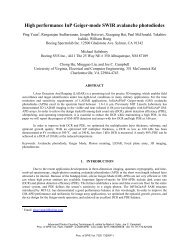
Figure 2 The electric field profile during operation <strong>Geiger</strong>-<strong>mode</strong> operation of an APD.<br />
The right panel shows PDE as function of DCR of three typical <strong>Spectrolab</strong> 25-µm diameter<br />
<strong>Geiger</strong>-<strong>mode</strong> APD pixels of a 32x128 array. The data are measured at various overbias points and<br />
at 243 K.<br />
In order to minimize the dark current generation in the narrow band absorber and maximize gain in the<br />
multiplier, the InGaAsP/InP GM-APD separate absorption and gain and multiplication (SAGM) device<br />
structure is tuned for 1.06 µm operation and the electric field profile is shown in<br />
Figure 2. Because both DCR and PDE increase with the overbias, for a better signal-to-noise ratio, the<br />
device operation point has to be carefully selected for the trade-off between PDE and DCR. The right panel<br />
plots the PDE against DCR of three 25-m array pixels on a 32x128 GM APD array under different<br />
overbiases and at 243K. Grown on p-type InP substrates, the devices can achieve 40% PDE with 3~4 kHz<br />
DCR at the operation temperature. The device growth, process and characterization details have been<br />
reported previously 2,3 .<br />
Figure 3 The two propagation paths for the secondary emission to a neighbor. The red<br />
line shows the surface emission reflected by the bottom. The blue line shows the lateral emission<br />
likely deflected to the high index substrate.
In each avalanche event, due to photon detection or dark count, a large amount of free carriers will be<br />
generated through the impact ionization process. The highest density of both carriers appears in the<br />
multiplication layer, and the probability of radiative recombination is non-negligible. Because all pixels in<br />
a GM APD array are biased beyond the breakdown voltage and they are extremely sensitive to single<br />
photon level in the detection gate, any secondary emission from a neighbor pixel can trigger false<br />
detections. If this crosstalk probability is not well controlled, the chain reaction can turn on the whole array<br />
with a single input photon and severely degrade the LADAR image quality. As the pixel pitch reduced<br />
from 100 µm of the previously reported 32x32 GM APD arrays to 50 µm, the crosstalk is an even greater<br />
concern.<br />
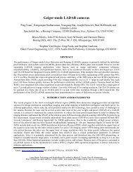
Figure 4 The crosstalk probability as a function of the distance to the initiating pixel of a<br />
50 um-pitch 32x128 <strong>Geiger</strong>-<strong>mode</strong> APD array under 4-V overbias. The pixel to pixel crosstalk is<br />
less than 60 ppm.<br />
In general, the secondary emission has two paths to propagate to the neighbors: surface emission and lateral<br />
emission. Due to the top metal contact, the surface emission can only go through the InP substrate. Because<br />
the secondary emission is primarily at the wavelength of the multiplier bandgap, the absorption in the N-<br />
filter layer in Figure 1 makes the first barrier for the crosstalk. The bottom of the array is covered by the<br />
AR coated incident window and metalized contact. The leftover secondary photons will either go through<br />
the AR coating with little reflection or get absorbed by another absorption layer deposited with the metal<br />
contact. For large pitch arrays, the solid angle of the cross section of the neighbor pixels is very small and<br />
the lateral emission is often of less concern. Compared to planar APD structures, the low index passivation<br />
layer gives mesa devices another layer of protection. Because of the high index contrast between the InP<br />
substrate and passivation material, the passivation layer between pixels makes a very lossy waveguide such<br />
that even less secondary photons can make the way to the neighbors. Figure 4 shows the pixel to pixel<br />
crosstalk of a 50 um-pitch 32x128 <strong>Geiger</strong>-<strong>mode</strong> APD array under 4-V overbias. The distance is in the unit<br />
of pixel pitch, and the crosstalk is less than 60 ppm, or 0.006% for all the distances.
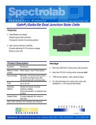
Figure 5<br />
<strong>Spectrolab</strong> 32x32 <strong>Geiger</strong>-<strong>mode</strong> LADAR camera and its internal configuration.<br />
Parameter Unit SPL SCA<br />
<strong>Format</strong><br />
32x32<br />
Pitch um 100<br />
Max frame rate kHz 20<br />
Bin size ns 0.5<br />
Jitter ns 0.43<br />
Output<br />
Basic CL<br />
Volume In 4x4x4<br />
Power W 25<br />
Table 1<br />
The specifications of <strong>Spectrolab</strong> 32x32 <strong>Geiger</strong>-<strong>mode</strong> APD LADAR camera.<br />
3. SPECTROLAB GEN-II 32X32 LADAR CAMERA<br />
With capacities in MOVPE epitaxy, wafer process, and module packaging, <strong>Spectrolab</strong> vertically integrated<br />
the LADAR camera manufacturing in house. After the detector array fabrication, Indium bumps were<br />
evaporated on to the array pixels. The detector array was integrated with a ROIC of the same format by<br />
flip-chip bonding. A GaP microlens array was attached to the focal plane array for a better fill factor<br />
afterward. The FPA and the interposer were mounted on to a TE cooler and the assembly was soldered in a<br />
69-pin grid array package. Later, the package was hermetically sealed with an AR-coated sapphire window.<br />
Under the support of DARPA, a 32x32 readout-integrated circuit (ROIC was designed in 180-nm CMOS<br />
technology. Many improvements were incorporated in this design based on our experience with the<br />
previous versions. They include: short pixel protection, 4-bit APD array NUB correction, 6.7 s gate width<br />
with 0.5 ns resolution (or 1000 m range with 7.5 cm resolution), 435-ps whole system jitter, negligible<br />
chirp and pulse skew, and 300 mW power consumption. Figure 5 shows the picture of this camera and its<br />
internal configuration. Table 1 lists the basic specifications of the <strong>Spectrolab</strong> 32x32 <strong>Geiger</strong>-<strong>mode</strong> APD<br />
LADAR camera.
Figure 6 The timing and operation sequence of a detection cycle of <strong>Spectrolab</strong> 32x32<br />
<strong>Geiger</strong>-<strong>mode</strong> APD LADAR camera.<br />
Figure 6 illustrates the timing and operation sequence of a detection cycle of this LADAR camera. The<br />
trigger can be generated internally or externally. Before the delivery, the trigger format will be selected<br />
between LVDS or LVTTL. The synchronization with the laser is realized with the isolated BNC trigger<br />
input and output ports on the back of the camera. After the camera is triggered, the sensor array will be<br />
armed and ready for detection. The delay between the trigger and gate-on is a combination of the circuit<br />
internal delay, which is about 80-100 ns, and the user specified gate delay. If the camera is used as a trigger<br />
master, a laser delay relative to the camera trigger can also be inserted. As a result, there will be a delay<br />
between the laser pulse out and sensor gate on, which defines the nearest range of this configuration while<br />
the sensor gate width determines the sensitive range from this point. By changing this delay, the camera<br />
sensitive range can be shifted from 0 m to the maximum range allowed by the sensor sensitivity, the laser<br />
power, and optics. If there is optical return in the sensitive range or sensor gate, the imaging pixels will be<br />
fired and the timing bins of these pixels will be latched in registers till the end of the gate. So, the fired<br />
pixels will remain blind in the rest of the gate period. With a bin size of 0.5 ns, the <strong>Spectrolab</strong> camera has a<br />
ranging resolution of 7.5 cm without interpolation. The 14-bit timing dynamic range enables a usable gate<br />
up to 6.7 us, or 1 km. At the end of the gate, the unfired pixels are forced to fire such that all the registers<br />
have ranging information. Then, the ranging information is scanned and downloaded, and the circuit is<br />
reset.<br />
Figure 7 Uniformity of a 32x32 array. The left panel shows the breakdown voltage map<br />
of a 32x32 APD array. Each color represents a 0.25 V voltage range. The breakdown voltage<br />
increases from the lower left corner to the upper right corner. The right panel shows the firing<br />
probability map of the same array under a uniform bias and uniform illumination.<br />
Uniformity is a critical array and camera performance. As shown in Figure 7, APD arrays have natural<br />
variations in breakdown voltage, which results in a performance variation across the array if it is biased<br />
under a uniform bias. As the breakdown voltage increases from the lower left corner to the upper right
corner, the sensitivity decreases in the same pattern in a camera assembled with this array under a uniform<br />
bias and uniform illumination.<br />
Bad pixel due to high dark current<br />
Figure 8 The firing probability map of the same 32x32 array after NUB correction and its<br />
array dark current map.<br />
By introducing a 4-bit 2.5V in-pixel programmable NUB adjustment, the <strong>Spectrolab</strong> 32x32 LADAR<br />
camera can program the bias of each individual pixels and improve the array sensitivity uniformity. Figure<br />
8 shows the firing probability map of the same 32x32 array after this NUB correction, and the standard<br />
deviation of the firing probability decreases from 1.99% to 1.20%. Obviously, the sensitivity uniformity of<br />
the camera is greatly improved.<br />
Figure 9 The Firing probability map of the same 32x32 array after NUB programming to<br />
enhance the sensitivity of four 4x4 regions.<br />
This function also allows array windowing: increased or decreased sensitivity within a specified region.<br />
Figure 9 demonstrated four 4x4 regions with enhanced sensitivity near the array center. Working like a<br />
digital optical aperture, this windowing function can avoid the interference and cross talk from other pixels<br />
out of the target area.<br />
Short pixel protection is another important feature implemented in this ROIC. With the immunity to<br />
sparse shorted detectors normally in APD arrays, this protection in the front end circuit greatly improves<br />
manufacturability and stability of FPAs.
The ROIC power consumption is reduced to 300 mW, about 50% of the previous version. Because the FPA<br />
is at the top of several stages of TECs, which consume most of the power in a LADAR camera, the nearly<br />
halved ROIC power consumption dramatically reduced the camera power load and heatsink weight.<br />
x 10 4 x 6755 y 35689 t 127207 12.5 2.17<br />
4<br />
3.5<br />
3<br />
2.5<br />
2<br />
1.5<br />
1<br />
0.5<br />
0<br />
6745 6747 6749 6751 6753 6755 6757 6759 6761 6763 6765<br />
4<br />
x 10 4 x 6755 y 35689 t 127207 12.5 2.17<br />
3.5<br />
3<br />
2.5<br />
2<br />
1.5<br />
1<br />
0.5<br />
0<br />
6745 6747 6749 6751 6753 6755 6757 6759 6761 6763 6765<br />
Figure 10<br />
demonstrated.<br />
Possitive and negative pulse skew of a 2ns laser pulse. 100 ps pulse resolution is<br />
With data accumulated from multiple frames and/or large objects, the pulse amplitude information can be<br />
extracted from the timing histogram. By interpolating the pulse magnitude, the pulse timing resolution can<br />
be improved beyond the limit of the timing bin size. A 2 ns laser pulse was moved by 100 ps in delay each<br />
time as shown in Figure 10. In both directions, the camera can easily distinguish the delay difference in the<br />
histogram with a resolution no less than 100 ps, though the pulse width is 2 ns and the bin size is 500 ps.
Figure 11<br />
The top graph shows the temporal histogram of a single laser pulse<br />
detected by a <strong>Spectrolab</strong> 32x32 LADAR camera. The overall system RMS jitter is about 418 ps.<br />
The bottom panel shows a series of signals detected from laser pulses delayed by 500 ns from each<br />
other. The data of all the delays is attached.<br />
The ranging accuary of a LADAR camera is determined by its overall jitter and chirp performance. The<br />
temporal histogram of our Gen-II 32x32 camera to a synchronized 90 ps laser pulse is shown in the top<br />
panel of Figure 11. The bin size is 500 ps, and the laser pulse width is included in this measurement. By<br />
calculating the standard deviation of this temporal distribution, we can get the overall system RMS jitter of<br />
418 ps, which includes the laser pulse width and jitters in the trigger loop, APDs, ROIC, and readout<br />
boards and is shorter than the 500ps bin size. With a new clock design, the chirp in this camera is<br />
negligible. As shown in the bottom panel of Figure 11, by increasing the delay of a laser pulse 500 ns each<br />
time, we have got a series of evenly spaced signals in the detection gate. The error of the pulse spaces is<br />
controlled within 0.1 ps, which matches well with the ranging resolution demonstrate above.<br />
4. SPECTROLAB 32X128 LADAR CAMERA<br />
For higher aerial mapping and 3D imaging efficiency, <strong>Spectrolab</strong> developed a 32x128 GM-APD SCA as<br />
reported previously 3 . Based on this effort and the experience in our 32x32 SCAs, the commercial 32x128<br />
SCA has incorporated many new features, including full Cameralink control and output, 50 kHz frame rate<br />
at all gate width, programmable 0.3 ~ 0.5 ns bins, 14-bit timing resolution, short pixel protection, and 4-bit<br />
NUB correction. Although the size is four times of that of the 32x32 SCAs, the power consumption is kept<br />
at 600 mW. Compared to <strong>Spectrolab</strong> 32x32 20kHz LADAR camera, the higher frame rate and larger<br />
format increase the data throughput by about 7x to 2.8 Gb/s. Full CameraLink and Coaxpress control and<br />
output ports will be implemented in this camera.
1…<br />
1…<br />
Vbr (V)<br />
115<br />
1…<br />
1…<br />
97<br />
91<br />
85<br />
79<br />
73<br />
Vbr Distribution<br />
Row<br />
67<br />
61<br />
55<br />
Figure 12. The breakdown voltage map of a 32x128 APD array at room temperature. Each<br />
color represents a 0.25 V range.<br />
The 32x128 APD arrays were fabricated with improved dark current uniformity and crosstalk performance.<br />
The breakdown voltage map is shown in Figure 12, and its range is well within the NUB capacity.<br />
The FPA is located in the center of the SCA. Similar to the 32x32 SCAs, the final assembly will be<br />
hermetically sealed in a 160-pin PGA package with the same size and footprint. Based on this SCA<br />
development, the next generation GmAPD 32x128 LADAR camera will be demonstrated soon.<br />
5. SUMMARY<br />
For large format SWIR LADAR cameras, <strong>Spectrolab</strong> developed the technologies for uniform small pitch<br />
array fabrication, small-pitch array crosstalk suppression, large data stream handling, and low power ROIC<br />
operation. With these technologies, <strong>Spectrolab</strong> demonstrated <strong>Geiger</strong>-<strong>mode</strong> APD arrays with 3-4 kHz DCR<br />
with 40% PDE, 60 ppm pixel-pixel crosstalk probability with 50 um pitch, and 0.16-V breakdown voltage<br />
standard deviation. Assembled with the arrays and newly developed ROIC, the <strong>Spectrolab</strong> 32x32 LADAR<br />
camera can open the gate up to 1 km with 0.5 ns bin size. The pulse skew tests show the measurement<br />
resolution can be improved to 100 ps with little chirp across the whole gate. The NUB function greatly<br />
improved the camera sensitivity uniformity. The 32x128 LADAR camera, currently under development,<br />
inherits all the features from the 32x32 version with large format and 43 kHz frame rate.<br />
ACKNOWLEDGEMENTS<br />
We would like to acknowledge the invaluable assistance provided by MIT Lincoln Laboratory and early<br />
stage funding from DARPA (Contract HR0011-08-C-0020) over the last several years.<br />
49<br />
REFERENCES<br />
1 K. A. McIntosh, et al., “Arrays of III-V semiconductor <strong>Geiger</strong>-<strong>mode</strong> avalanche photodiodes,” Lasers and<br />
Electro-Optics Society, 2003. LEOS 2003. The 16th Annual Meeting of the IEEE. Volume 2, 686 (2003).<br />
2 R. Sudharsanan, et al., “Single photon counting <strong>Geiger</strong> Mode InGaAs(P)/InP avalanche photodiode<br />
arrays for 3D imaging,” Proc. SPIE 6950, 69500N (2008).<br />
3 P. Yuan, et al., “<strong>Geiger</strong>-<strong>mode</strong> LADAR cameras,” Proc. SPIE 8037, 803712 (2011).<br />
43<br />
37<br />
31<br />
25<br />
19<br />
13<br />
86.5 86.8 87.0 87.3 87.5 87.8 88.0 85.0 85.3 85.5 85.8 86.0 86.3<br />
7<br />
Column<br />
1<br />
87.8-88.0<br />
87.5-87.8<br />
87.3-87.5<br />
87.0-87.3<br />
86.8-87.0<br />
86.5-86.8<br />
86.3-86.5<br />
86.0-86.3<br />
85.8-86.0<br />
85.5-85.8<br />
85.3-85.5