High performance InP Geiger-mode SWIR avalanche ... - Spectrolab
High performance InP Geiger-mode SWIR avalanche ... - Spectrolab
High performance InP Geiger-mode SWIR avalanche ... - Spectrolab

You also want an ePaper? Increase the reach of your titles
YUMPU automatically turns print PDFs into web optimized ePapers that Google loves.
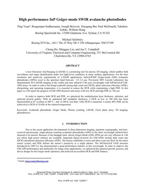
<strong>High</strong> <strong>performance</strong> <strong>InP</strong> <strong>Geiger</strong>-<strong>mode</strong> <strong>SWIR</strong> <strong>avalanche</strong> photodiodes<br />
Ping Yuan 1 , Rengarajan Sudharsanan, Joseph Boisvert, Xiaogang Bai, Paul McDonald, Takahiro<br />
Isshiki, William Hong<br />
Boeing <strong>Spectrolab</strong> Inc. 12500 Gladstone Ave. Sylmar, CA 91342<br />
Michael Salisbury<br />
Boeing SVS Inc., 4411 The 25 Way NE # 350 Albuquerque, NM 87109<br />
Chong Hu, Mingguo Liu, and Joe C. Campbell<br />
University of Virginia, Electrical and Computer Engineering, 351 McCormick Rd<br />
Charlottesville, VA 22904-4743<br />
ABSTRACT<br />
LAser Detection And Ranging (LADAR) is a promising tool for precise 3D-imaging, which enables field<br />
surveillance and target identification under low-light-level conditions in many military applications. For the time<br />
resolution and sensitivity requirements of LADAR applications, InGaAsP/<strong>InP</strong> <strong>Geiger</strong>-<strong>mode</strong> (GM) <strong>avalanche</strong><br />
photodiodes (APDs) excel in the spectrum band between 1.0~1.6 µm. Previously MIT Lincoln Laboratory has<br />
demonstrated 3D LADAR imaging in the visible and near infrared (1.06 µm) wavelengths with <strong>InP</strong>/InGaAsP GM-<br />
APD arrays. In order to relieve the design tradeoffs among dark count rate (DCR), photo detection efficiency (PDE),<br />
afterpulsing, and operating temperature, it is essential to reduce the DCR while maintaining a high PDE. In this<br />
paper we will report the progress of GM-APD detectors and arrays with low DCR and high PDE at 1.06 µm.<br />
In order to improve both DCR and PDE, we optimized the multiplication layer thickness, substrate, and<br />
epitaxial growth quality. With an optimized <strong>InP</strong> multiplier thickness, a DCR as low as 100 kHz has been<br />
demonstrated at 4V overbias at 300 o C. and at 240 K, less than 1 kHz DCR is measured. A nearly 40% PDE can be<br />
achieved at a DCR of 10 kHz at the reduced temperature.<br />
Keywords: Avalanche photodiode, <strong>Geiger</strong> Mode, Photon counting, LIDAR, Focal plane array, 3D imaging,<br />
photodetector.<br />
1. INTRODUCTION<br />
Due to the recent application developments in three-dimension imaging, quantum cryptography, and timeresolved<br />
spectroscopy, single-photon counting <strong>avalanche</strong> photodiodes (APD) in the short wavelength infrared have<br />
attracted a lot interest. Because of the bandgap limit, silicon <strong>Geiger</strong>-Mode (GM) APDs are not very efficient at 1.06<br />
µm where high power emitters are available. Important figure-of-merits for GM-APDs include dark count rate<br />
(DCR) and photon detection efficiency (PDE). The former establishes a noise and false event rate floor for the entire<br />
sensor system, and PDE defines the sensor’s sensitivity to a single photon. The <strong>InP</strong>/InGaAsP SAM structure<br />
introduced by MIT-LL has demonstrated a good <strong>performance</strong> balance at this wavelength. In order to improve the<br />
GM-APD <strong>performance</strong> and uniformity for image array applications, we optimized the epitaxial growth, process, and<br />
device design for the <strong>Geiger</strong>-<strong>mode</strong> operation, and achieved an excellent DCR and PDE balance.<br />
1 Email: ping.yuan@Boeing.com<br />
Advanced Photon Counting Techniques III, edited by Mark A. Itzler, Joe C. Campbell,<br />
Proc. of SPIE Vol. 7320, 73200P · © 2009 SPIE · CCC code: 0277-786X/09/$18 · doi: 10.1117/12.821284<br />
Proc. of SPIE Vol. 7320 73200P-1
2. DEVICE STRUCTURE<br />
The device structure follows the traditional separate absorption and charge multiplication (SACM) design:<br />
using InGaAsP as the absorber for 1.06 µm and <strong>InP</strong> as the multiplication layer. A low electric field is applied<br />
throughout this low band-gap absorber layer to minimize the tunneling and <strong>avalanche</strong> multiplication while keep<br />
carriers drift in the proper direction. The multiplication layer has to be exposed to a high internal field in order to<br />
promote the impact ionization of photo-carriers. A precisely controlled charge layer is inserted between these two<br />
layers.<br />
n-InGaAs<br />
n-<strong>InP</strong><br />
E<br />
InGaAs i-InGaAs<br />
or InGaAsP<br />
InGaAsP Graded layer<br />
N-<strong>InP</strong> Charge layer<br />
h<br />
e<br />
P side<br />
i-<strong>InP</strong> Multiplier<br />
P-<strong>InP</strong> Buffer 2<br />
P-<strong>InP</strong> Buffer 1<br />
Absorber<br />
<strong>InP</strong> Multiplier<br />
Figure 1 The cross section of the <strong>InP</strong>/InGaAsP <strong>Geiger</strong>-Mode APD epitaxial stack and its typical<br />
electric field profile at operation. For the following analysis, the origin is at the <strong>InP</strong> charge and<br />
multiplier interface.<br />
The <strong>InP</strong>/InGaAsP APD structure cross section is shown in Figure 1, and the right figure shows the resultant<br />
electric field profile at the operating bias. The thin heavily doped InGaAs capping layer was grown for good ohmic<br />
contacts. Under this layer is an N-doped <strong>InP</strong> window layer, followed by an InGaAsP absorber layer. The material<br />
quality and doping level of this narrow band material were closely monitored to minimize the thermal generation<br />
and avoid excess electric field and carrier traps. The thickness and doping of the n-type charge layer were carefully<br />
controlled. At the bottom is a heavily doped p-type <strong>InP</strong> layer, followed by an <strong>InP</strong> buffer layer, also heavily doped.<br />
3. GEIGER-MODE OPERATION<br />
Figure 2 shows a typical current-voltage characteristics of an <strong>InP</strong>/InGaAsP APD. As the bias voltage<br />
reaches the breakdown voltage, the device currents, dark or photo, approach infinity, or the current compliance in<br />
practice because of the carrier <strong>avalanche</strong> ionization. So, it is impossible to bias an APD beyond the breakdown<br />
voltage for a long time. However, since it takes some time for the injection to take place and for the <strong>avalanche</strong><br />
process to build up, it is possible to bias the device for a short period and quench the current once it reaches a certain<br />
threshold. The resultant short current pulse will be amplified in the following circuit and registered as an event. If<br />
the photon generated injection dominates the carrier injection into the multiplier, the APD can serve as a good single<br />
photon detector.<br />
Proc. of SPIE Vol. 7320 73200P-2
1.E-04<br />
1.E-05<br />
1.E-06<br />
9764-11 40 µm<br />
100<br />
Current<br />
1.E-07<br />
1.E-08<br />
10<br />
Gain<br />
1.E-09<br />
1.E-10<br />
1.E-11<br />
40.0 50.0 60.0 70.0 80.0<br />
Figure 2 The current-voltage and gain characteristics of a 40 µm <strong>Spectrolab</strong> <strong>InP</strong>/InGaAsP 1.06 µm<br />
GM APD.<br />
V<br />
1<br />
Photon detection efficiency, which is the ratio of the resultant pulses to the incident photons, describes the<br />
APD photon sensitivity at the single photon level. Following the photo carrier generation and multiplication process,<br />
we can identify the four factors influencing PDE. They are the absorber’s absorption efficiency η abs =(1-exp -aWa ),<br />
which is a function of the absorption coefficient a and absorber thickness W a , the transportation efficiency η tran , the<br />
injection efficiency η inj , and <strong>avalanche</strong> probability P(0) for a hole injection at the absorber and multiplier interface as<br />
shown in Figure 1. So,<br />
PDE = η η η P(0) . (1)<br />
abs<br />
tran<br />
inj<br />
In the SAM APD structure, there is a low electric field in the absorber and the <strong>InP</strong>/InGaAsP interface such<br />
that the transportation efficiency η tran and the injection efficiency η inj are close to 1. The absorption efficiency η abs is<br />
mainly determined by the absorber thickness, and it is normally controlled to be greater than 70%. So, PDE is<br />
primarily determined by P(0) in a SAM structure.<br />
In the following analysis, we will employ the McIntyre APD theory because most of the <strong>Geiger</strong>-<strong>mode</strong><br />
APDs are based on a thick multiplier, where the local ionization <strong>mode</strong>l is fairly accurate 1 . In the end, we see the<br />
advantage of thick multipliers, which explains its popularity in this application. Based on McIntyre’s analysis, P(0)<br />
is a function of the electron ionization coefficient α, the hole ionization coefficient β, and the multiplier thickness<br />
W m . However, even in a constant electric field, it has to be numerically solved. In practice, P(0) has to be controlled<br />
to nearly 50% for an PDE in the range of 30~40%.<br />
In the absence of incident photon, there is still a probability for the GM-APD to break down, or dark count<br />
rate (DCR), due to the carrier injections from the thermal generation and tunneling in the absorber region, carrier<br />
detrapping at the absorber and multiplier interface, and tunneling in the multiplier. With a careful bandgap and<br />
electric field design, the dark generation in the absorber and detrapping at the interface can be well controlled at<br />
Proc. of SPIE Vol. 7320 73200P-3
educed temperatures. In practice, the carrier tunneling in the multiplier dominates the dark count generation at the<br />
operation condition in a 1.06 µm GM device.<br />
The multipliers of most SAM APD structures are unintentionally doped and the electric field is nearly<br />
constant. Based on McIntyre’s theory 1 , the <strong>avalanche</strong> probability of an e-h pair injection at x in a constant field E is<br />
1<br />
P(<br />
x)<br />
=<br />
1−<br />
P(0)<br />
1+<br />
e<br />
P(0)<br />
( β −α<br />
) x<br />
1<br />
=<br />
1−<br />
P(0)<br />
1+<br />
e<br />
P(0)<br />
x / Lαβ<br />
(2)<br />
where L αβ =1/(β-α) and characterizes the decay of P(x) in the multiplier. Because P(0), α and β are functions of E,<br />
P(x) is eventually determined by E and x. The band-to-band tunneling generation through a parabolic barrier is<br />
described by 2,3 3 / 2<br />
BE<br />
2<br />
g<br />
Gmul<br />
( x)<br />
= AE exp( − )<br />
E<br />
2 2mr<br />
e<br />
(3)<br />
eEg<br />
π mr<br />
/ 2 2mcmlh<br />
A = , B = , mr<br />
=<br />
3 2<br />
4π<br />
h 2eh<br />
mc<br />
+ mlh<br />
where m c is the conductance band effective mass and m lh is the light hole effective mass. Then, the DCR due to<br />
tunneling in the multiplier with a constant field is<br />
∫<br />
Wm<br />
0<br />
dxG<br />
mul<br />
( x)<br />
P(<br />
x)<br />
= G<br />
1−<br />
P(0)<br />
K = ≈ 1<br />
P(0)<br />
mul<br />
( x)<br />
W<br />
m<br />
⎡ L<br />
⎢1<br />
−<br />
⎣ W<br />
m<br />
1+<br />
Ke<br />
ln<br />
1+<br />
K<br />
W / Lαβ<br />
⎤<br />
⎥ = G<br />
⎦<br />
( x)<br />
W<br />
Combining the above dark count generation mechanisms, we can get the total DCR of a device with an area of S in a<br />
constant field<br />
DCR = S<br />
[ G ( E)<br />
W R + G w P(0)<br />
G P(0)<br />
]<br />
The ratio of Eq. 5 and 1 gives the DCR equivalent flux (DEF) in the gate period, which is an important figure of<br />
merit of photon-counting devices. Based on the equation below,<br />
αβ<br />
mul m abs abs<br />
+<br />
m<br />
trap<br />
mul<br />
m<br />
R<br />
(4)<br />
(5)<br />
DEF<br />
DCR S ⎛ WmR<br />
= = ⎜Gmul<br />
( E)<br />
+ Gabswabs<br />
+ Gtrap<br />
PDE η<br />
abs ⎝ P(0)<br />
⎞<br />
⎟<br />
⎠<br />
(6)<br />
a higher quantum efficiency η abs is always preferable, but the background doping in the actual growth limits the<br />
absorber thickness to 1-2 µm for a better electric field control. For an efficient optical coupling, there is also a limit<br />
in reducing the device area S. It is important to pursue the best crystal quality to reduce all the generations, G mul ,<br />
G abs , and G trap , but the product of GWR indicates another avenue to improve the device <strong>performance</strong> while the<br />
multiplier thickness is subject to optimization. As the thickness of the multiplier W m increases, the electric field<br />
decreases, as does the tunneling generate rate G mul . Based on the reported α and β of <strong>InP</strong> at room temperature 4 , the<br />
breakdown electric field and breakdown voltage were plotted as a function of the thickness in the left panel of<br />
Figure 3. In the same thickness range, the tunneling injection efficiency R shown in Equation 4 and the product of<br />
GWR were illuminated in the right panel. As the electric field decreases, the tunneling injection efficiency R<br />
Proc. of SPIE Vol. 7320 73200P-4
changes little and maintains a value around 0.40 to 0.42 for <strong>InP</strong>, and the decrease of the tunneling generation<br />
dominates the trend over the increase of thickness W m . A very similar R value and the same trend with the multiplier<br />
thickness were obtained with another set of reported α and β of <strong>InP</strong> 5 , though there is considerable difference in the<br />
absolute values between the two ionization data sets. So, based on the above analysis, a thicker multiplier with a<br />
lower breakdown electric field is preferable to achieve a lower DEF <strong>performance</strong> at room temperature. Due to the<br />
difficulty in obtaining the low-temperature ionization coefficient data 3 , the above analysis was not carried to lower<br />
temperatures. However, based on observation that the dark count rate of all <strong>InP</strong> GM APDs decreases with about the<br />
same rate over temperature, the room-temperature <strong>performance</strong> can serve as a good guidance in the device<br />
optimization.<br />
4. GROWTH AND PROCESS<br />
The APD structures were grown on two-inch <strong>InP</strong> substrates in a multi-wafer MOVPE production reactor.<br />
Trimethylindium (TMIn), trimethylgallium (TMGa), arsine (AsH3) and phosphine (PH3) were used as sources for<br />
In, Ga, As, and P, respectively. Silicon and zinc were used as n- and p- type dopants, respectively. The growth<br />
parameters, such as growth temperature, V/III ratio, and dopant concentration, were optimized for the latticematched<br />
<strong>InP</strong> and InGaAsP layers with the designed thicknesses and doping concentrations. X-ray diffraction,<br />
Dektak, electrochemical-capacitance–voltage (ECV), photoluminescence, and SIMS techniques were employed to<br />
characterize the as-grown wafers.<br />
A Bromine/Methanol solution was used to etch the device mesa. Polyimide and SiNx layers were deposited<br />
onto the sidewalls to cap and seal the devices. The typical Ti/Pt/Au and Au/Ge/Ni/Au metal stacks were deposited<br />
for p and n contacts, respectively. Backside processing was standard for making n type contacts. For the front-side<br />
illuminated devices, a more complex process sequence was needed for the front contact. Anti-reflection (AR) layers<br />
were typically single quarter wave stacks tuned to the desired wavelength.<br />
E (1e5 V/cm)<br />
E, Vbr-W<br />
6.0<br />
100<br />
90<br />
5.5<br />
80<br />
5.0<br />
70<br />
60<br />
4.5<br />
50<br />
40<br />
4.0<br />
30<br />
3.5<br />
20<br />
10<br />
3.0<br />
0<br />
0.5 1.0 1.5 2.0<br />
M Thickness (um)<br />
Vbr (V)<br />
GWR (a.u.)<br />
GWR, R-W<br />
2.5E-05<br />
1.0<br />
0.9<br />
2.0E-05<br />
0.8<br />
0.7<br />
1.5E-05<br />
0.6<br />
0.5<br />
1.0E-05<br />
0.4<br />
0.3<br />
5.0E-06<br />
0.2<br />
0.1<br />
0.0E+00<br />
0.0<br />
0.5 1.0 1.5 2.0<br />
M Thickness (um)<br />
R<br />
Figure 3 The breakdown electric field and voltage are plotted as a function of the undoped <strong>InP</strong><br />
multiplier thickness at room temperature. Appreciable decrease in the electric field is observed. Based<br />
on the reported ionization coefficients, the tunneling carrier injection efficiency R and the product of<br />
GWR are calculated as a function of the multiplier thickness. In the thickness range of interest, the<br />
decrease of G mul dominates the trend over the increase of W m while R keeps nearly constant.<br />
Proc. of SPIE Vol. 7320 73200P-5
Vbr (V)<br />
100.0<br />
90.0<br />
80.0<br />
70.0<br />
60.0<br />
50.0<br />
40.0<br />
30.0<br />
20.0<br />
10.0<br />
0.0<br />
Vbr-W<br />
0.5 1.0 1.5 2.0<br />
M Thickness (um)<br />
Figure 4 The curve shows the calculated breakdown voltage as function of the undoped <strong>InP</strong><br />
multiplier thickness at room temperature based on the ionization coefficients reported in Ref. 4. This<br />
is the same curve shown in the left panel of Figure 3. The measured Vbr and multiplier thickness of<br />
the fabricated devices were illuminated with crosses in the Vbr-M space, and show a good agreement<br />
5. RESULTS AND DISCUSSIONS<br />
In the device structure optimization, a series of <strong>InP</strong>/InGaAsP GM APD with various multiplier thicknesses<br />
were grown and processed. The dark current and photo response of the GM APDs were characterized with a<br />
computer-controlled Keithley 238 source meter. For simplicity and accuracy, the 1.06 µm laser beam in a single<br />
<strong>mode</strong> fiber was coupled through a lens and the AR coated surface of the front illuminated devices. Figure 2<br />
illustrated the I-V curves of a 40-µm-diameter device measured at room temperature. The dark current stays below<br />
100 pA before breakdown, which is essential for a low DCR. A punch-though can be observed in the photo response<br />
at about 63V, and above this bias the absorber is fully depleted, but it also provides a low field across the absorber<br />
even beyond breakdown. An appreciable gain was measured before breakdown, and it implies a good PDE when the<br />
device is biased in the <strong>Geiger</strong> <strong>mode</strong>. In order to overcome some unintended doping in the absorber and keep a good<br />
PDE at low temperature, a reasonable separation before the punchthrough and breakdown has to be maintained. The<br />
CV characteristics were measured with an Agilent E4980A and a Keithley 590. The <strong>InP</strong> multiplier and InGaAsP<br />
absorber thicknesses can be determined by the CV results. In order to compare with the thickness-vs-breakdown<br />
voltage curve shown in Figure 3, the voltage drop across the absorber has to be subtracted from the total device<br />
breakdown voltage. The voltage applied to the multiplier at breakdown can be deduced with the two thicknesses, the<br />
punchthrough and breakdown voltages. In Figure 4 experimentally determined breakdown voltage and layer<br />
thickness were plotted against the calculated curved based on the ionization data from Ref. 4. A good agreement was<br />
achieved, and it also helps to verify the accuracy of the ionization coefficient data used in the above analysis, at least<br />
in the electric field range of interest.<br />
In <strong>Geiger</strong>-<strong>mode</strong> DCR and PDE measurements operation, the APD is biased to just below the breakdown<br />
voltage, and an overbias pulse of a few volts is applied in a gate time of a few nanoseconds. The room-temperature<br />
DCR <strong>performance</strong> of the 1.06 µm APDs fabricated at <strong>Spectrolab</strong> is shown in Figure 5. For the convenience of<br />
comparison, all the devices have a diameter of 30 µm. In a series of effort, the thickness of the multiplier ranges<br />
Proc. of SPIE Vol. 7320 73200P-6
from about 1.0 µm to 1.6 µm. Coupled with the improvements in growth and substrates, the DCR of the 30 µm<br />
APDs improved from nearly 1 MHz at 4V overbias to 100 kHz at room temperature.<br />
10.00<br />
1.00<br />
8702-11C3<br />
9569-9 D30-4<br />
9590-11 D30-4<br />
9690-10 D30<br />
9764-11 D30<br />
DCR Data-Room Temp<br />
DCR (MHz)<br />
9970-10 D30<br />
0.10<br />
0.01<br />
0 1 2 3 4 5 6<br />
Overbias (V)<br />
Figure 5 The DCR at room temperature versus overbias characteristics taken on a series of of InGaAsP-<strong>InP</strong><br />
GM-APDs. The thickness of the multipliers ranges from 1.0 µm to 1.6 µm. With other improvements in<br />
growth and substrates, the DCR is reduced by a decade to about 100 kHz at 4 V overbias at room<br />
temperature.<br />
The temperature variation of DCR of three typical devices was measured at MIT-LL. As shown in Figure 6,<br />
starting from about the same DCR difference at room temperature, the DCR of all the devices decreases with about<br />
the same ratio over the temperature. For comparison, all the data shown in Figure 6 were measured at 4V overbias<br />
on 30 µm devices. At 240 K, the DCR of <strong>Spectrolab</strong> 9764 is reduced to less than 1 kHz at 4 V overbias. Compared<br />
with our earlier effort with 8702 and 9569, the improvement in DCR is greater than a decade at the reduced<br />
temperature.<br />
As is well known 6 , both DCR and PDE decrease with overbias and temperature. For the best trade-off of<br />
the operation conditions for the GM-APDs, the photon detection efficiency (PDE) were measured as a function of<br />
overbias and plotted versus DCR as shown in Figure 7. The PDE data were measured with 1.06 µm laser pulses<br />
shorter than 1 nanosecond, and the overbias gate pulses were carefully synchronized with these laser pulses. 9764<br />
series 1.06 µm GM-APDs demonstrated an efficiency nearly 40% with a DCR of about 10 kHz at 250 o C.<br />
Proc. of SPIE Vol. 7320 73200P-7
DCR (Hz)<br />
1.E+06<br />
1.E+05<br />
1.E+04<br />
n+ Sumi, SL9569,<br />
30um<br />
n+ Sumi, SL9690,<br />
30um<br />
p+ Sumi, SL9764,<br />
30um<br />
1.E+03<br />
1.E+02<br />
200 220 240 260 280 300<br />
Temp (K)<br />
Figure 6 The temperature variation of DCR of three typical InGaAsP-<strong>InP</strong> GM APDs. As the<br />
thickness of the multiplier increases from nearly 1.0 µm to 1.6 µm, the DCR decreased<br />
dramatically, and the improvement at lower temperature is even greater than a decade. The DCR<br />
data was taken at 4V overbias on 30 µm devices at MIT-LL.<br />
1.E+05<br />
SpectroLab 9764-10, 250K, 30 micron<br />
1.E+04<br />
DCR (Hz)<br />
1.E+03<br />
1.E+02<br />
0.0 10.0 20.0 30.0 40.0 50.0<br />
PDE (%)<br />
Figure 7 The DCR-vs-PDE chart of a 30-µm device of 9764 at 250 K. Nearly 40% PDE at 1.06<br />
µm can be achieved with a DCR of 10 kHz.<br />
Proc. of SPIE Vol. 7320 73200P-8
6. CONCLUSIONS<br />
In order to improve the overall <strong>performance</strong> of the InGaAsP-<strong>InP</strong> <strong>Geiger</strong>-<strong>mode</strong> APD for the 1.06 µm<br />
applications, the SAM structure was carefully analyzed and a figure of merit, DEF, was proposed. As shown in the<br />
analysis, as well as proven in experiment, a thicker <strong>InP</strong> multiplier is essential to reduce the DCR from room<br />
temperature to about 200 K. With other improvements in epitaxial growth quality and substrate, a DCR as low as 1<br />
kHz has been demonstrated at 4V overbias at 240 o C. A nearly 40% PDE was achieved at a DCR of 10 kHz at the<br />
reduced temperature.<br />
7. REFERENCE<br />
1 R. J. McIntyre, “On the Avalanche Initiation Probability of Avalanche Diodes Above the Breakdown Voltage,” IEEE<br />
Transactions on Electron Devices, vol. 20, no. 7, July, 1973.<br />
2 S. M. Sze, Physics of Semiconductor Devices, New York: Wiley, 1981, pp. 520-527.<br />
3 J.P. Donnelly, E. K. Duerr, A. McIntosh,E. A. Dauler, D.C. Oakley, S. H. Groves, C.J. Vineis, L.J. Mahoney, K.M.<br />
Molvar, P.I. Hopman, K.E. Jensen, G.M. Smith, S. Verghese, D.C. Shaver, “Design Considerations for 1.06-mm<br />
InGaAsP-<strong>InP</strong> <strong>Geiger</strong>-Mode Avalanche Photodiodes,” IEEE Journal of Quantum Electronics, vol, 42, no. 8, August,<br />
2006.<br />
4 Cook, L. W.; Bulman, G. E.; Stillman, G. E., “Electron and hole impact ionization coefficients in <strong>InP</strong> determined by<br />
photomultiplication measurements,” Appl. Phys. Lett., vol. 40, no. 7, pp.589-591, April, 1982.<br />
5 C. A. Amiento and S. H. Groves, “Impact ionization in (100)-, (110)-,and (111)-oriented <strong>InP</strong> <strong>avalanche</strong> photodiodes,”<br />
Appl. Phys. Lett., vol. 43, no. 2, pp. 333–335, July 1983.<br />
6 S. Verghese, J.P. Donnelly, E.K. Duerr, A. McIntosh, D.C. Chapman, C.J. Vineis, G.M. Smith, J.E. Funk, K.E. Jensen,<br />
P.I. Hopman, D.C. Shaver, B.F. Aull, J.C. Aversa, J.P. Frechette, J.B. Glettler, Z.L. Liau, J.M. Mahan, L.J. Mahoney,<br />
K.M. Molvar, F.J. O’Donnell, D.C. Oakley, E.J. Ouellette, M.J. Renzi, and B. M. Tyrrell, “Arrays of <strong>InP</strong>-based<br />
Avalanche Photodiodes for Photon Counting,” IEEE J. of Selected Topics in Quantum Electronics, vol. 13, no. 4,<br />
July/August, 2007.<br />
Proc. of SPIE Vol. 7320 73200P-9