SBP30 Sealed Balanced Pressure Thermostatic ... - Spirax Sarco
SBP30 Sealed Balanced Pressure Thermostatic ... - Spirax Sarco
SBP30 Sealed Balanced Pressure Thermostatic ... - Spirax Sarco

You also want an ePaper? Increase the reach of your titles
YUMPU automatically turns print PDFs into web optimized ePapers that Google loves.
TI-P120-01<br />
ST Issue 6<br />
Cert. No. LRQ 0963008<br />
ISO 9001<br />
<strong>SBP30</strong><br />
<strong>Sealed</strong> <strong>Balanced</strong> <strong>Pressure</strong> <strong>Thermostatic</strong> Steam Trap<br />
<strong>SBP30</strong><br />
1<br />
2<br />
4<br />
3<br />
5<br />
check valve<br />
<strong>SBP30</strong>LCV<br />
<strong>SBP30</strong>HCV<br />
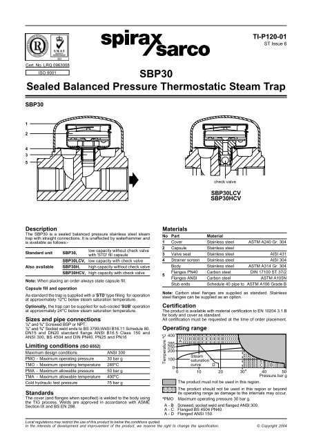
Description<br />
The <strong>SBP30</strong> is a sealed balanced pressure stainless steel steam<br />
trap with straight connections. It is unaffected by waterhammer and<br />
is available as follows:-<br />
low capacity without check valve<br />
Standard unit <strong>SBP30</strong>,<br />
with 'STD' fill capsule<br />
<strong>SBP30</strong>LCV, low capacity with check valve<br />
Also available <strong>SBP30</strong>H, high capacity without check valve<br />
<strong>SBP30</strong>HCV, high capacity with check valve<br />
Note: When placing an order always state capsule fill.<br />
Capsule fill and operation<br />
As standard the trap is supplied with a 'STD' type filling for operation<br />
at approximately 12°C below steam saturation temperature.<br />
Optionally, the trap can be supplied for sub-cooled 'SUB' operation<br />
at approximately 24°C below steam saturation temperature.<br />
Sizes and pipe connections<br />
½" and ¾" Screwed BSP or NPT.<br />
½" and ¾" Socket weld ends to BS 3799/ANSI B16.11 Schedule 80.<br />
DN15 and DN20 standard flange ANSI B16.5 Class 150 and<br />
ANSI 300, BS 4504 and DIN PN40, PN25 and PN16<br />
Limiting conditions (ISO 6552)<br />
Maximum design conditions ANSI 300<br />
PMO - Maximum operating pressure 30 bar g<br />
TMO - Maximum operating temperature 285°C<br />
PMA - Maximum allowable pressure 50 bar g<br />
TMA - Maximum allowable temperature 400°C<br />
Cold hydraulic test pressure<br />
75 bar g<br />
Standards<br />
The cover (and flanges when specified) is welded to the body using<br />
the TIG process. Welds are approved in accordance with ASME<br />
Section IX and BS EN 288.<br />
Materials<br />
No Part Material<br />
1 Cover Stainless steel ASTM A240 Gr. 304<br />
2 Capsule Stainless steel<br />
3 Valve seat Stainless steel AISI 431<br />
4 Strainer screen Stainless steel AISI 304<br />
Body Stainless steel ASTM A314 Gr. 304<br />
5<br />
Flanges PN40 Carbon steel DIN 17100 ST 37/2<br />
Flanges ANSI Carbon steel ASTM A105N<br />
Stub ends Schedule 40 pipe to ASTM A106 Grade B<br />
Note: Carbon steel flanges are supplied as standard. Stainless<br />
steel flanges can be supplied as an option.<br />
Certification<br />
The product is available with material certification to EN 10204 3.1.B<br />
for body and cover as standard.<br />
All certification must be requested at the time of order placement.<br />
Operating range<br />
Temperature °C<br />
400<br />
A<br />
285<br />
250<br />
200<br />
Steam<br />
100 saturation<br />
curve D<br />
C B<br />
0<br />
0 10 20 30 * 40 50<br />
<strong>Pressure</strong> bar g<br />
The product must not be used in this region.<br />
The product should not be used in this region or beyond<br />
its operating range as damage to the internals may occur.<br />
*PMO Maximum operating pressure 30 bar g.<br />
A - B Screwed, socket weld and flanged ANSI 300.<br />
A - C Flanged BS 4504 PN40.<br />
A - D Flanged ANSI 150.<br />
Local regulations may restrict the use of this product to below the conditions quoted.<br />
In the interests of development and improvement of the product, we reserve the right to change the specification. © Copyright 2004
Capacities<br />
3000<br />
2000<br />
Dimensions / weights (approximate) in mm and kg<br />
Weight<br />
Size A A1 B C D Scr /SW FIg<br />
½" - DN15 80 150 63 56 19 1.0 2.4<br />
¾" - DN20 80 150 63 56 19 1.0 2.4<br />
Condensate kg/h<br />
1000<br />
500<br />
400<br />
300<br />
200<br />
<strong>SBP30</strong>H<br />
<strong>SBP30</strong>H<br />
<strong>SBP30</strong>HCV<br />
<strong>SBP30</strong>HCV<br />
<strong>SBP30</strong> and <strong>SBP30</strong>LCV<br />
<strong>SBP30</strong> and <strong>SBP30</strong>LCV<br />
C<br />
D<br />
B<br />
100<br />
1 2 3 4 5 10 20 30<br />
Differential pressure bar (x 100 = kPa)<br />
Hot water capacity<br />
Cold water capacity<br />
Safety information<br />
<strong>Pressure</strong><br />
Before attempting any maintenance of the steam trap, consider<br />
what is or may have been in the pipeline. Ensure that any pressure<br />
is isolated and safely vented to atmospheric pressure before<br />
attempting to maintain the steam trap. This is easily achieved by<br />
fitting <strong>Spirax</strong> <strong>Sarco</strong> depressurisation valves type DV (see separate<br />
literature for details). Do not assume that the system is depressurised<br />
even when a pressure gauge indicates zero.<br />
Temperature<br />
Allow time for temperature to normalise after isolation to avoid the<br />
danger of burns and consider whether protective clothing (including<br />
safety glasses) is required.<br />
Installation<br />
The trap is designed for installation with the capsule in a horizontal<br />
plane and the cover at the top, preferably with a drop leg immediately<br />
preceding the trap. When welding the trap into the pipeline, there is<br />
no need to remove the capsule, providing the welding is done by the<br />
electric arc method. Suitable isolation valves must be installed to<br />
allow for safe maintenance and trap replacement. Remove all<br />
protective caps prior to installation. Open isolation valves slowly<br />
until normal operating conditions are achieved. Check for leaks and<br />
correct operation.<br />
Maintenance<br />
Maintenance can be initiated once the safety procedures have been<br />
observed. It is important to renew the complete assembly as there<br />
are no servicable parts. When maintenance is complete, open<br />
isolation valves slowly and check for leaks.<br />
Disposal<br />
This product is recyclable. No ecological hazard is anticipated with<br />
the disposal of this product, providing due care is taken.<br />
How to order<br />
Example: 1 off ½" <strong>Spirax</strong> <strong>Sarco</strong> <strong>SBP30</strong> sealed balanced pressure<br />
steam trap. Screwed BSP with 'STD' fill capsule for operation at<br />
approximately 12°C below steam saturation temperature.<br />
A<br />
A1<br />
<strong>SBP30</strong> <strong>Sealed</strong> <strong>Balanced</strong> <strong>Pressure</strong> <strong>Thermostatic</strong> Steam Trap TI-P120-01 ST Issue 6