590+ Series DC Digital Converter - ssdservice.pl
590+ Series DC Digital Converter - ssdservice.pl
590+ Series DC Digital Converter - ssdservice.pl

You also want an ePaper? Increase the reach of your titles
YUMPU automatically turns print PDFs into web optimized ePapers that Google loves.
6047##,QVWDOOLQJ#WKH#&RQYHUWHU<br />
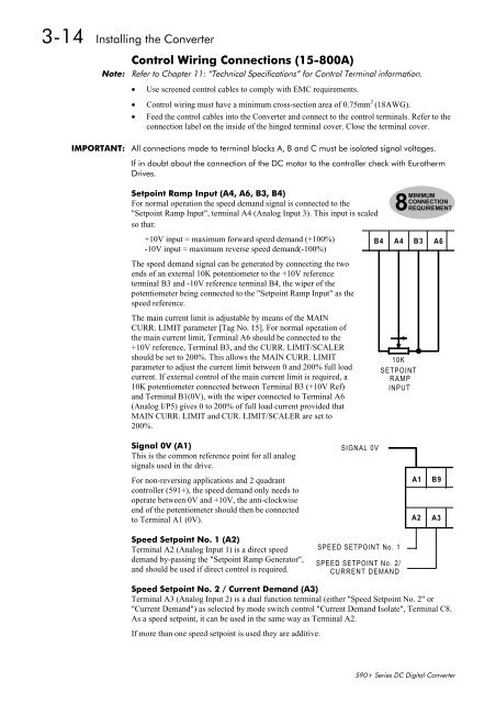
&RQWURO#:LULQJ#&RQQHFWLRQV#+480;33$,<br />
1RWH=# 5HIHU#WR#&KDSWHU#44=#´7HFKQLFDO#6SHFLILFDWLRQVµ#IRU#&RQWURO#7HUPLQDO#LQIRUPDWLRQ1<br />
• Use screened control cables to com<strong>pl</strong>y with EMC requirements.<br />
• Control wiring must have a minimum cross-section area of 0.75mm 2 (18AWG).<br />
• Feed the control cables into the <strong>Converter</strong> and connect to the control terminals. Refer to the<br />
connection label on the inside of the hinged terminal cover. Close the terminal cover.<br />
,03257$17=# $OO#FRQQHFWLRQV#PDGH#WR#WHUPLQDO#EORFNV#$/#%#DQG#&#PXVW#EH#LVRODWHG#VLJQDO#YROWDJHV1<br />
,I#LQ#GRXEW#DERXW#WKH#FRQQHFWLRQ#RI#WKH#'&#PRWRU#WR#WKH#FRQWUROOHU#FKHFN#ZLWK#(XURWKHUP<br />
'ULYHV1<br />
6HWSRLQW#5DPS#,QSXW#+$7/#$9/#%6/#%7,<br />
For normal operation the speed demand signal is connected to the<br />
"Setpoint Ramp Input", terminal A4 (Analog Input 3). This input is scaled<br />
so that:<br />
+10V input = maximum forward speed demand (+100%)<br />
B4<br />
-10V input = maximum reverse speed demand(-100%)<br />
The speed demand signal can be generated by connecting the two<br />
ends of an external 10K potentiometer to the +10V reference<br />
terminal B3 and -10V reference terminal B4, the wiper of the<br />
potentiometer being connected to the "Setpoint Ramp Input" as the<br />
speed reference.<br />
The main current limit is adjustable by means of the MAIN<br />
CURR. LIMIT parameter [Tag No. 15]. For normal operation of<br />
the main current limit, Terminal A6 should be connected to the<br />
+10V reference, Terminal B3, and the CURR. LIMIT/SCALER<br />
should be set to 200%. This allows the MAIN CURR. LIMIT<br />
parameter to adjust the current limit between 0 and 200% full load<br />
current. If external control of the main current limit is required, a<br />
10K potentiometer connected between Terminal B3 (+10V Ref)<br />
and Terminal B1(0V), with the wiper connected to Terminal A6<br />
(Analog I/P5) gives 0 to 200% of full load current provided that<br />
MAIN CURR. LIMIT and CUR. LIMIT/SCALER are set to<br />
200%.<br />
MINIMUM<br />
CONNECTION<br />
8REQUIREMENT<br />
A4<br />
10K<br />
SETPOINT<br />
RAMP<br />
INPUT<br />
B3<br />
A6<br />
6LJQDO#39#+$4,<br />
This is the common reference point for all analog<br />
signals used in the drive.<br />
For non-reversing ap<strong>pl</strong>ications and 2 quadrant<br />
controller (591+), the speed demand only needs to<br />
operate between 0V and +10V, the anti-clockwise<br />
end of the potentiometer should then be connected<br />
to Terminal A1 (0V).<br />
6SHHG#6HWSRLQW#1R1#4#+$5,<br />
Terminal A2 (Analog Input 1) is a direct speed<br />
demand by-passing the "Setpoint Ramp Generator",<br />
and should be used if direct control is required.<br />
SIGNAL 0V<br />
SPEED SETPOINT No. 1<br />
SPEED SETPOINT No. 2/<br />
CURRENT DEMAND<br />
A1<br />
A2<br />
B9<br />
A3<br />
6SHHG#6HWSRLQW#1R1#5#2#&XUUHQW#'HPDQG#+$6,<br />
Terminal A3 (Analog Input 2) is a dual function terminal (either "Speed Setpoint No. 2" or<br />
"Current Demand") as selected by mode switch control "Current Demand Isolate", Terminal C8.<br />
As a speed setpoint, it can be used in the same way as Terminal A2.<br />
If more than one speed setpoint is used they are additive.<br />
8