Beosound 3000 Type 2671-2680 .pdf - abo - center
Beosound 3000 Type 2671-2680 .pdf - abo - center
Beosound 3000 Type 2671-2680 .pdf - abo - center

Create successful ePaper yourself
Turn your PDF publications into a flip-book with our unique Google optimized e-Paper software.
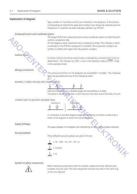
2.1 Explanation of diagram<br />
Explanation of diagram<br />
<strong>Type</strong> numbers of transistors and ICs are indicated on the diagrams. If the position<br />
is followed by an asterisk the spare part number must always be used because the<br />
component in question has been specially selected, e.g. TR102*.<br />
ABO-CENTER v/HENRIKSENS ELEKTRONIK<br />
Component print and coordinate system<br />
The largest PCBs have component prints and a coordinate system on both the print<br />
and the component side.<br />
On the diagrams every component has a coordinate number. This indicates in which<br />
coordinate on the PCB the component is situated. The coordinate numbers are<br />
written in smaller print types than the position numbers.<br />
Control circuit<br />
In certain control circuits the active mode is indicated by a function term or by an<br />
abbreviation. This may be e.g. ST.BY. = low in the stand-by mode or ST.BY. = high<br />
in the stand-by mode.<br />
Wiring connections<br />
The wiring connections on the diagrams are assembled in ‘bundles’. The individual<br />
wires are provided with one of the following codes:<br />
INTERNAL CONNECTION ON ONE DIAGRAM PAGE<br />
12 20 20 12<br />
Internal connections on a diagram page are indicated by a number.<br />
The bend of the wire indicates in wich direction the other end of the wire is found.<br />
CONNECTION TO ANOTHER DIAGRAM PAGE<br />
DIAGRAM A<br />
DIAGRAM C<br />
C3 C32 A32 A3<br />
A connection to another diagram page is indicated by a number as well as by a<br />
letter of the diagram to which the connection leads.<br />
Supply Voltages<br />
All supply voltages in the diagrams are indicated by an arrow and a voltage indication.<br />
Ground symbols<br />
Three different ground symbols are used in the set.<br />
= RF - OSC - SH - IF1 - IF2 - A<br />
= Chassis<br />
= D<br />
Symbol of safety components<br />
When replacing components with this symbol, components with identical part<br />
numbers must be used. The new component must be mounted in the same way<br />
as the one replaced.