DJLab.3 - Stanton
DJLab.3 - Stanton
DJLab.3 - Stanton

Create successful ePaper yourself
Turn your PDF publications into a flip-book with our unique Google optimized e-Paper software.
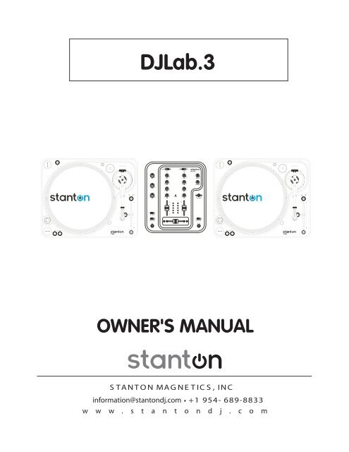
<strong>DJLab.3</strong><br />
OWNER'S MANUAL<br />
S TA N T O N MA G N E T IC S , IN C<br />
information@stantondj.com +1 954- 689-8833<br />
w w w . s t a n t o n d j . c o m
IMPORTANT TO SAFETY<br />
1. Read these Instructions<br />
2. Keep these Instructions<br />
3. Heed all Warnings<br />
4. Follow all Instructions<br />
5. Do not use this apparatus near water<br />
6. Clean only with dry cloth<br />
7. Do not block any ventilation openings. Install in<br />
accordance with the manufacturer’s instructions.<br />
8. Do not install near any heat sources such as radiators,<br />
hear registers, stoves, or other apparatus (including<br />
amplifiers) that produce heat.<br />
9. Do not defeat the safety purpose of the polarized or<br />
grounding-type plug. A polarized plug has two blades with<br />
one wider than the other. A grounding type plug has two<br />
blades and a third grounding prong. The wide blade or the<br />
third prong are provided for your safety. If the provided plug<br />
does not fit into your outlet, consult an electrician for<br />
replacement of the obsolete outlet.<br />
10. Protect the power cord from being walked on or pinched<br />
particularly at plugs, convenience receptacles, and the<br />
point where they exit from the apparatus.<br />
11. Only use attachments/accessories specified by the<br />
manufacturer.<br />
12.<br />
Use only with the cart, stand, tripod,<br />
bracket, or table specified by the<br />
manufacturer, or sold with the apparatus.<br />
When a cart is used, use caution when<br />
moving the cart/apparatus combination to<br />
avoid injury from tip-over.<br />
13. Unplug this apparatus during lightning storms or when<br />
unused for long periods of time.<br />
14. Refer all servicing to qualified <strong>Stanton</strong> service center.<br />
Servicing is required when the apparatus has been<br />
damaged in any way, such as power-supply cord or plug<br />
is damaged, liquid has been spilled or objects have<br />
fallen into the apparatus, the apparatus has been<br />
exposed to rain or moisture, does not operate normally,<br />
or has been dropped.<br />
15. This appliance shall not be exposed to dripping or<br />
splashing water and that no object filled with liquids<br />
such as vases shall be placed on apparatus.<br />
IMPORTANT SAFETY INSTRUCTIONS<br />
CAUTION<br />
CAUTION: To reduce the risk of electric shock, do not remove<br />
the cover (or back). No user-serviceable parts inside. Refer<br />
servicing to qualified service personnel.<br />
The lightning flash with arrowhead symbol within an equilateral triangle is intended to alert the use to<br />
the presence of un-insulated “dangerous voltage” within the product’s enclosure that may be of<br />
sufficient magnitude to constitute a risk of electric shock to persons.<br />
The exclamation point within the equilateral triangle is intended to alert the user to the presence of<br />
important operating and maintenance (servicing) instructions in the literature accompanying the<br />
appliance.<br />
CAUTION<br />
To prevent electric shock, do not use this polarized plug with an extension cord, receptacle or other outlet unless<br />
the blades can be fully inserted to prevent blade exposure.
LINE VOLTAGE SELECTION<br />
115V<br />
230V<br />
1) The desired voltage of your turntable may be set with the VOLTAGE SELECTOR switch on the<br />
rear panel of the main unit, using a screwdriver.<br />
2) Do not twist the VOLTAGE SELECTOR switch with excessive force as this may cause damage.<br />
3) If the VOLTAGE SELECTOR switch does not move smoothly contact a qualified serviceman.<br />
• 3 band EQ w/ input GAIN control per channel.<br />
• Power on/off muting.<br />
• Long-lasting crossfader.<br />
• Crossfader Start Function<br />
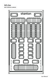
M.202 FEATURES<br />
M.202 CONTENTS
M.202 CONTENTS<br />
When used with a compatible CD player, you can use<br />
the crossfader to start and stop the CD player with the<br />
slide of the fader. The fader start switch activates the<br />
fader start feature. When in the ON position, the fader<br />
start allows the fader to return automatically to preset<br />
digital CUE POINTS on your compatible STANTON DJ<br />
CD Player.<br />
14) Mic EQ – The mic channel include a two-band EQ with a<br />
range of +10dB to –10dB.<br />
<br />
<br />
<br />
<br />
<br />
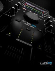
1) Input fader - Controls individual source levels/volume<br />
(channels) in the mix.<br />
2) Input toggle switch - Selects which source will be active<br />
based on what you have connected to the rear panel<br />
input section (phono/line).<br />
3) Channel EQ - Adjusts the high, mid and low<br />
frequency levels of the input channels for good<br />
sound.<br />
4) Channel Gain – Adjusts the pre-fader volume for<br />
cleaner sound.<br />
5) Replaceable Crossfader - Achieves clean fades<br />
between the two input channels. "Hard left" selects<br />
Channel 1. "Hard right" selects Channel 2. With the<br />
crossfader centered, both channels are live. Use<br />
the crossfader for fast and seamless fades from<br />
one channel to the other.<br />
6) Mic Input Gain – Adjusts microphone input level.<br />
7) Mic Input – Insert your Microphone with ¼” plug here.<br />
8) Headphone Output – Insert in the ¼” plug for your<br />
headphones here.<br />
9) Channel Cue / Cue Pan - Used to preview channel<br />
audio to your headphones. Listen here before bringing<br />
up channel faders or moving the crossfader.<br />
10) Headphone Level – Adjusts cue volume.<br />
11) Master Level - Controls the overall output level.<br />
12) Crossfader Curve – The CUT setting allows the use of the<br />
crossfader for quick cut in and out when scratching and<br />
mixing. The FADE setting is used for longer segues,<br />
typically when mixing between two beat-matched<br />
sources.<br />
15) Level Indicators – The dual LED indicators are used to<br />
indicate the master output level of channels Right and<br />
Left.<br />
16) Grounding post - for turntable connection. Always use<br />
this connection when using standard turntables with<br />
ground cable. (Some turntables like the T.80 / T.120 do<br />
not require grounding wire)<br />
17) Phono Inputs – Plug your turntables in here. When these<br />
connectors are used, your signal is fed directly to the<br />
high-quality RIAA phono pre-amplifiers. Use this position<br />
only for turntables. Line level sources will overload the<br />
sensitive phono pre-amps and will cause distortion.<br />
18) Line Inputs - Unbalanced RCA jacks for connecting<br />
stereo audio from line level sources such as CD players,<br />
HiFi VCRs, cassette decks, DAT machines, laser discs,<br />
tuners, even synthesizers or other mixing consoles.<br />
NOTE: Plug mono audio sources into both Left and<br />
Right inputs using a "Y" cable connector.<br />
19) Master Output - Unbalanced RCA connectors controlled<br />
by the Master level.<br />
20) Fader Start – This function works in conjunction with a<br />
compatible fader start CD player. When used with a<br />
compatible CD player, you can use the crossfader to<br />
start and stop the CD player with the slide of the fader.<br />
The fader start switch activates the fader start feature.<br />
When in the ON position, the fader start allows the fader<br />
to return automatically to preset digital CUE POINTS on<br />
your compatible STANTON DJ CD Player.<br />
21) Power Connector - Plug in the included power supply<br />
here.<br />
22) Power Switch – turns unit off and on. Note*** Remember<br />
to turn ALL volume levels down when turning the unit<br />
on/off.<br />
13) Fader start – This function works in conjunction with a<br />
compatible fader start CD player.
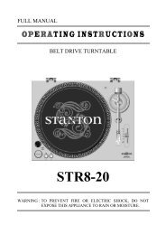
QUICK SETUP DIAGRAM<br />
Study this setup diagram. Make sure all faders are at "zero" and all devices are off. First, connect all input sources. Next,<br />
connect your microphone and monitor headphones. Finally, connect the stereo outputs to the power amplifier(s) and/or audio<br />
receivers such as tape decks. Plug your mixer into AC power. Now you are ready to switch everything on. IMPORTANT:<br />
Always switch on your audio input sources such as turntables or CD players first, then your mixer, and finally any amplifiers.<br />
When turning off, always reverse this operation by turning off amplifiers, then your mixer, and then input devices.
SPECIFICATIONS<br />
M.202<br />
INPUT / OUTPUT IMPEDANCE & SENSITIVITY:<br />
LINE -14dB/10K OHM ±2dB<br />
PHONO -50dB /47K OHM ±2dB<br />
MIC -60dB /2.2K OHM ±2dB<br />
MASTER 1K OHM<br />
PHONES 0dB/33 OHM ±2dB (LOAD=32 OHM)<br />
MAX. OUTPUT (THD=1%)<br />
MASTER MORE THAN +14dBV<br />
PHONES MORE THAN +21dBV<br />
CHANNEL BALANCE<br />
WITHIN 3dB<br />
FREQUENCY RESPONSE:<br />
LINE 20-20KHz ±2dB<br />
PHONO 20-20KHz +2, -3dB (RIAA)<br />
MIC 20-20KHz +2/-3dB<br />
OUTPUT NOISE (IEC-A WEIGHTED)<br />
LINE LESS THAN -90dBV<br />
PHONO LESS THAN -80dBV<br />
MIC LESS THAN -50dBV<br />
THD + N: (MASTER 0dBV OUTPUT, MAXIMUM GAIN, w/ 20kHz LPF)<br />
LINE LESS THAN 0.05% 20 - 20KHz<br />
PHONO LESS THAN 0.1% 20 - 20KHz (IEC-A WTD)<br />
MIC LESS THAN 0.2% 20 - 20KHz (IEC-A WTD)<br />
PHONES LESS THAN 0.1% 20 - 20KHz (FROM LINE INPUT)<br />
CROSSTALK<br />
LESS THAN -80dB AT 1KHz BETWEEN CHANNELS.<br />
(TERMINATED UNUSED INPUTS)<br />
MIC EQ<br />
HI<br />
LOW<br />
±10 +/- 2dB AT 10KHz<br />
±10 +/- 2dB AT 100Hz<br />
CHANNEL EQ<br />
HI 9 +/- 2dB AT 13KHz<br />
-15 +/- 3dB AT 13KHz<br />
MID 9 +/- 2dB AT 1KHz<br />
LESS THAN -23dB AT 1KHz<br />
LOW 9 +/- 2dB AT 70Hz<br />
-26 +/- 3dB AT 70Hz<br />
POWER SOURCE<br />
DIMENSIONS<br />
WEIGHT<br />
AC 9V,1000mA<br />
230 (W) X 267 (D) X 111 (H) mm<br />
1.65Kgs
CONNECTIONS<br />
1) Connect the power cord to an AC outlet.<br />
2) Connect the RCA cable to the PHONO input of your mixer. You can also use a line input by setting the<br />
phono/line switch at the rear of the turntable to Line.<br />
Note: This turntable has separate analog and digital circuits. If you are looking for a purely analog signal, use the<br />
Phono output. For access to the Key Lock feature use the Line output or S/P DIF output.<br />
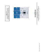
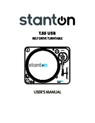
T.80 TURNTABLE CONTENTS
T.80 TURNTABLE CONTENTS<br />
1) Start/Stop<br />
2) Strobe Dots<br />
3) Slipmat<br />
4) Center Spindle<br />
5) Motor ON/OFF Switch<br />
6) Platter Revolution Speeds (RPM)<br />
7) Target Light Base<br />
8) Key Lock<br />
9) Pitch Lock<br />
10) Pitch Slider<br />
11) Headshell Locking Nut<br />
12) Tonearm<br />
13) Pitch Select<br />
14) Tone Arm Base<br />
15) Counterweight<br />
16) 45-rpm Adaptor Holder<br />
17) Extra Stylus Holder<br />
18) Reverse<br />
19) Phono/Line Output<br />
20) Phono/Line Switch<br />
21) Digital Output<br />
22) Power Cord Connector/Power Switch<br />
TONE ARM AND CARTRIDGE SETTINGS<br />
The major cause of problems in sound and skipping on the vinyl is the lack of proper set up of the needle and turntable<br />
adjustments. The needle is designed to operate at a specific angle to the vinyl. The T.80 has several adjustments to correctly<br />
position the needle to the vinyl.<br />
The first adjustment is the correct installation of the cartridge.<br />
Your cartridge is to be mounted into the headshell as pre the mounting instructions included with the cartridge. The <strong>Stanton</strong><br />
500,680 and 890 series of cartridges require the use of the two screws mounting into the headshell. For your convenience,<br />
some of these products can be purchased already mounted and pre-adjusted from your local <strong>Stanton</strong> dealer. If you are using<br />
these 1/2” mounted products with a headshell in a mobile application or you are doing heavy scratching, May want to use an<br />
extra shell weight. The Master series of products (Trackmaster, Groovemaster, etc.) are designed with their own mounting that<br />
eliminates the need for a separate headshell and the wiring to the cartridge.<br />
The body of the cartridge should be parallel with the centerline of the headshell-tone arm, when viewed from the front to the<br />
back.<br />
The second adjustment is at the installation of the cartridge-head-shell assembly into the tone arm tube lock. Holding<br />
the tone arm tube in one hand, insert the cartridge-headshell into the tube lock with the other hand. Turn the lock ring<br />
clockwise (when viewed from the rear) until the headshell is locked tightly into the tone arm. Remove the needle protector from<br />
the cartridge and place the needle on record. View the needle from the front and insure that the needle is perpendicular to the<br />
record surface. If some adjustment is needed, simply loosen the lock ring and rotate the cartridge-headshell until the needle is<br />
perpendicular to the record surface. Then re-tighten the lock ring.<br />
The third adjustment is the needle (or stylus) pressure. Start with the cartridge-headshell assembly mounted into the tone<br />
arm. Remove any needle protectors provided. With tone arm free, adjust the tone arm counterweight by rotating the rear<br />
section until the tone arm floats in a balanced condition above the record or mat. Do not allow the needle to drop onto the mat<br />
or the turntable platter during this adjustment. You might damage the needle tip. Now, carefully hold the tone arm in one hand<br />
while rotating the numbered ring on the front of the counter-weight with the other hand to the “0” setting. Next, without touching<br />
the numbered ring, Rotate the rear counterweight until the desired needle pressure reading is next to the line on top of the tone<br />
arm tube, see the instructions. Included with your cartridge for proper settings.<br />
ASSEMBLY<br />
Remove all the parts from the box. Please check to make<br />
sure the following items are included with the main unit in the<br />
carton:<br />
(1) Platter<br />
(2) Slip mat<br />
(3) Counterweight<br />
(4) 45-rpm adapter<br />
(5) 500B Cartridge and Headshell<br />
(6) AC cord<br />
(7) RCA cable<br />
(8) Target light<br />
(9) Operating instructions<br />
(10) Cloth dust cover
SPECIFICATIONS<br />
T.80<br />
POWER SOURCE<br />
AC 100V, 50/60Hz (For Japan)<br />
AC 110V, 60Hz (For Taiwan)<br />
AC 120V, 60Hz (For U.S.A.,Canada,Mexico)<br />
AC 220V, 50Hz (For United Arab Emirates,Chile,Argentina)<br />
AC 220V, 60Hz (For Philippines)<br />
AC 230V, 50Hz (For Europe,New Zealand,South Africa,Singapore,Israel)<br />
AC 240V, 50Hz (For Australia,U.K.)<br />
POWER CONSUMPTION 10 Watts<br />
DIMENSIONS<br />
WEIGHT<br />
452 (W) x 370 (D) x 86 (H) mm<br />
8.6 Kgs
<strong>Stanton</strong> Magnetics, Inc. – Warranty Provision – Returns for Repairs or Replacement<br />
WARRANTY<br />
Through <strong>Stanton</strong>’s authorized dealers around the World, <strong>Stanton</strong>, or one of <strong>Stanton</strong>’s authorized distributors outside the<br />
U.S., will, without charge, repair or replace, at the sole discretion of the entity responsible for making the repair or<br />
providing the replacement, any <strong>Stanton</strong> merchandise proved defective in material or workmanship for a period of one (1)<br />
year following the date of original purchase. Exceptions to this warranty are as noted below:<br />
The warranty for mechanical parts which are subject to wear and tear are limited to the earlier to occur of thirty (30) days<br />
following the date of original purchase or the following number of cycles: Faders - 15,000; Rotary potentiometers - 10,000;<br />
and Switches - 10,000.<br />
<strong>Stanton</strong> will warrant all replacement parts and repairs for ninety (90) days from the date of original shipment. Repairs<br />
made necessary by reason of misuse, alteration, normal wear, or accident are not covered under this warranty.<br />
RETURNS<br />
Authorized <strong>Stanton</strong> dealers are only authorized to sell and distribute merchandise within a specific country. All goods<br />
requiring warranty repair or replacement must be returned (freight prepaid if not hand-delivered) to the authorized <strong>Stanton</strong><br />
dealer from whom the merchandise was purchased and in the same country where the merchandise was purchased. For<br />
purposes of purchases made via the Internet, the merchandise must be returned to the authorized <strong>Stanton</strong> dealer in the<br />
country where the authorized <strong>Stanton</strong> dealer which sold the merchandise to purchaser is located and not the authorized<br />
<strong>Stanton</strong> dealer in the country where the purchaser is located or the country in which the merchandise was received. Any<br />
returns to a non-authorized dealer or to an authorized <strong>Stanton</strong> dealer not in the same country as the merchandise was<br />
intended to be sold or as set forth above will void this warranty.<br />
To initiate a warranty repair, you must contact the authorized <strong>Stanton</strong> dealer from whom you purchased the merchandise,<br />
and follow such authorized <strong>Stanton</strong> dealer’s return policy.<br />
<strong>Stanton</strong> assumes no risk and shall be subject to no liability for damages or loss resulting from the specific use or<br />
application made of the merchandise. <strong>Stanton</strong>'s liability for any claim, whether based on breach of contract, negligence,<br />
infringement of any rights of any party, or product liability, and relating to the merchandise shall not exceed the price<br />
received by <strong>Stanton</strong> from your purchase of such merchandise. In no event will <strong>Stanton</strong> be liable for any special, incidental<br />
or consequential damages (including loss of use, loss of profit and claims of third parties) however caused, whether by the<br />
negligence of <strong>Stanton</strong> or otherwise. To the extent permitted by law and except as otherwise provided above, <strong>Stanton</strong><br />
disclaims any express or implied warranties of merchantability or fitness for a particular purpose.<br />
The above warranty provides you with specific legal rights. You may also have additional rights, which are subject to<br />
variation from state to state and country to country.<br />
If there is a dispute regarding the warranty of merchandise that does not fall under the warranty conditions stated above,<br />
please include a written explanation with the merchandise when returned pursuant to the terms and conditions set forth<br />
herein.<br />
Please register your product online at www.stantondj.com or mail your completed warranty card to:<br />
<strong>Stanton</strong> Magnetics, Inc, 3000 SW 42 St. Hollywood, Florida 33312.
STANTON WARRANTY REGISTRATION CARD<br />
If you have internet access, please register your product at<br />
www.stantondj.com. Otherwise, return this card completely filled<br />
out in order to validate your warranty.<br />
PERSONAL INFO<br />
Name<br />
Address<br />
City State Zip<br />
Country<br />
Telephone<br />
PRODUCT INFO<br />
Model Number<br />
Serial Number<br />
Date of Purchase<br />
Where did you buy this product?<br />
cut along dotted line
<strong>Stanton</strong> Magnetics, Inc.<br />
3000 SW 42nd Street<br />
Hollywood, FL 33312<br />
U.S.A.<br />
PLACE<br />
STAMP<br />
HERE