11280A HercuLine Series Actuator Specification
11280A HercuLine Series Actuator Specification
11280A HercuLine Series Actuator Specification

You also want an ePaper? Increase the reach of your titles
YUMPU automatically turns print PDFs into web optimized ePapers that Google loves.
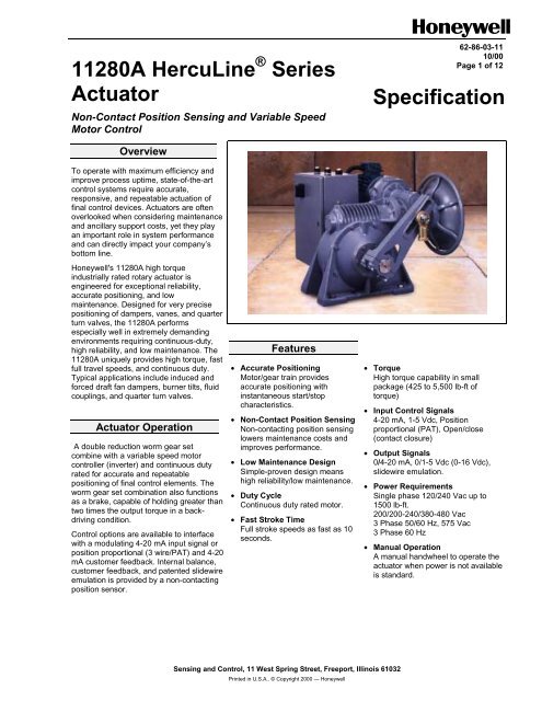
<strong>11280A</strong> <strong>HercuLine</strong> ® <strong>Series</strong><br />
<strong>Actuator</strong><br />
Non-Contact Position Sensing and Variable Speed<br />
Motor Control<br />
62-86-03-11<br />
10/00<br />
Page 1 of 12<br />
<strong>Specification</strong><br />
Overview<br />
To operate with maximum efficiency and<br />
improve process uptime, state-of-the-art<br />
control systems require accurate,<br />
responsive, and repeatable actuation of<br />
final control devices. <strong>Actuator</strong>s are often<br />
overlooked when considering maintenance<br />
and ancillary support costs, yet they play<br />
an important role in system performance<br />
and can directly impact your company’s<br />
bottom line.<br />
Honeywell's <strong>11280A</strong> high torque<br />
industrially rated rotary actuator is<br />
engineered for exceptional reliability,<br />
accurate positioning, and low<br />
maintenance. Designed for very precise<br />
positioning of dampers, vanes, and quarter<br />
turn valves, the <strong>11280A</strong> performs<br />
especially well in extremely demanding<br />
environments requiring continuous-duty,<br />
high reliability, and low maintenance. The<br />
<strong>11280A</strong> uniquely provides high torque, fast<br />
full travel speeds, and continuous duty.<br />
Typical applications include induced and<br />
forced draft fan dampers, burner tilts, fluid<br />
couplings, and quarter turn valves.<br />
<strong>Actuator</strong> Operation<br />
A double reduction worm gear set<br />
combine with a variable speed motor<br />
controller (inverter) and continuous duty<br />
rated for accurate and repeatable<br />
positioning of final control elements. The<br />
worm gear set combination also functions<br />
as a brake, capable of holding greater than<br />
two times the output torque in a backdriving<br />
condition.<br />
Control options are available to interface<br />
with a modulating 4-20 mA input signal or<br />
position proportional (3 wire/PAT) and 4-20<br />
mA customer feedback. Internal balance,<br />
customer feedback, and patented slidewire<br />
emulation is provided by a non-contacting<br />
position sensor.<br />
Features<br />
• Accurate Positioning<br />
Motor/gear train provides<br />
accurate positioning with<br />
instantaneous start/stop<br />
characteristics.<br />
• Non-Contact Position Sensing<br />
Non-contacting position sensing<br />
lowers maintenance costs and<br />
improves performance.<br />
• Low Maintenance Design<br />
Simple-proven design means<br />
high reliability/low maintenance.<br />
• Duty Cycle<br />
Continuous duty rated motor.<br />
• Fast Stroke Time<br />
Full stroke speeds as fast as 10<br />
seconds.<br />
• Torque<br />
High torque capability in small<br />
package (425 to 5,500 lb-ft of<br />
torque)<br />
• Input Control Signals<br />
4-20 mA, 1-5 Vdc, Position<br />
proportional (PAT), Open/close<br />
(contact closure)<br />
• Output Signals<br />
0/4-20 mA, 0/1-5 Vdc (0-16 Vdc),<br />
slidewire emulation.<br />
• Power Requirements<br />
Single phase 120/240 Vac up to<br />
1500 lb-ft.<br />
200/200-240/380-480 Vac<br />
3 Phase 50/60 Hz, 575 Vac<br />
3 Phase 60 Hz<br />
• Manual Operation<br />
A manual handwheel to operate the<br />
actuator when power is not available<br />
is standard.<br />
Sensing and Control, 11 West Spring Street, Freeport, Illinois 61032<br />
Printed in U.S.A.. © Copyright 2000 — Honeywell
62-86-03-11<br />
Page 2<br />
Features (continued)<br />
• Auto-Manual electric handswitch with<br />
auxiliary contacts indicating an "Out-of-<br />
Auto" position for local electric control is<br />
standard.<br />
• Output Shaft Hardware<br />
<strong>11280A</strong> series actuators are available<br />
with an adjustable radius (8”-14)/<br />
position crank arm and linkage kits<br />
• Limit Switches<br />
All 11280 series actuators are<br />
supplied with two end of travel<br />
limit switches and two auxiliary<br />
switches (SPDT).<br />
• Enclosure<br />
Rugged, weatherproof, industrial<br />
grade.<br />
• Full Travel Speed<br />
Full stroke travel speeds 10, 30 or<br />
60 seconds/90° travel, 120° travel<br />
speed is longer.<br />
• Warranty<br />
Exceptional warranty – 30 months<br />
from shipment or 24 months from<br />
date of installation.<br />
<strong>Actuator</strong> shaft<br />
extension<br />
Non-Contact Sensor Spoiler<br />
Shown in zero position for<br />
Counter Clockwise operation<br />
of the drive. (Clockwose rotation<br />
of Spoiler).<br />
Non-Contact<br />
Sensor<br />
Sensing PWA<br />
Allen Screw<br />
Output<br />
Board<br />
W11<br />
PIN #2<br />
"+"<br />
W11<br />
W11<br />
PIN #1<br />
"-"<br />
NCS Assembly
62-86-03-11<br />
Page 3<br />
Physical<br />
Weight<br />
Enclosure<br />
Gear train<br />
Mechanical stops<br />
Operating Temperature<br />
<strong>Specification</strong> - General<br />
56 kg to 224 kg (150-600 lb.) (see table below for specifics for each model)<br />
Precision machined ductile iron with corrosion resistant paint<br />
Precision machined, double reduction worm gear<br />
To prevent over-travel<br />
–30 °C to +65 °C (–20 °F to +150 °F)<br />
expect Model 11287A which has a range of: –20 °C to +65 °C (–4 °F to +150 °F)<br />
Storage Temperature –40 °C to +93 °C (–40 °F to +200 °F)<br />
Relative Humidity<br />
Crank Arm<br />
Adjustable radii (8” to 14”) crank arm is standard.<br />
Rotation<br />
90-120 degrees. Factory set at 90 degrees.<br />
Direction of Rotation<br />
Manual Handwheel<br />
Lubrication<br />
Fuses Bussmann GDB1.6: 1.6 Amp Fast<br />
Littlefuse 312001: 1.0 Amp Fast<br />
25 Am Fast<br />
Catalog # Torque Output Shaft Shaft Key Output Shaft<br />
lb-ft (N-M) Size<br />
Size Length<br />
11284A 425 (575) 2"<br />
(51 mm)<br />
11285A 850 (1150) 2"<br />
(51 mm)<br />
11286A 1500 (2025) 2"<br />
(51 mm)<br />
11288A 2500 (3400) 2-1/2"<br />
(64 mm)<br />
11289A 4000 (5425) 2-1/2"<br />
(64 mm)<br />
11287A 5500 (7450) 2-1/2"<br />
(64 mm)<br />
Electrical<br />
Power Input<br />
Motor<br />
Loss of Power<br />
Local Auto/Manual Switch<br />
Limit Switches<br />
Auxiliary Switches<br />
Fully operable over the range of 0-99 % R.H. non-condensing<br />
Field selectable via switch and jumper. Default = CCW (determined looking into the shaft)<br />
Provides a means of positioning the actuator in the event of a power failure or on set-up.<br />
Mobil Synthetic bearing and gear lubricant SHC 634 (ISO 460) or equivalent<br />
1/2"<br />
(13 mm)<br />
1/2"<br />
(13 mm)<br />
1/2"<br />
(13 mm)<br />
5/8"<br />
(16 mm)<br />
5/8"<br />
(16 mm)<br />
5/8"<br />
(16 mm)<br />
5"<br />
(127 mm)<br />
5"<br />
(127 mm)<br />
5"<br />
(127 mm)<br />
6"<br />
(152 mm)<br />
6"<br />
(152 mm)<br />
6"<br />
(152 mm)<br />
115/220 Vac, single phase 50/60 Hz up to 1500 lb-ft<br />
208/200 – 240/380 – 480/575, 30, 50/60 Hz<br />
Maximum<br />
Overhang<br />
Load<br />
3700 lb.<br />
(1380 kg)<br />
3700 lb.<br />
(1380 kg)<br />
3700 lb.<br />
(1380 kg)<br />
7500 lb.<br />
(2798 kg)<br />
7500 lb.<br />
(23798 kg)<br />
7500 lb.<br />
(23798 kg)<br />
Inverter rated, 3 phase, continuous duty, C face mounting<br />
Stays in Place<br />
Torque Settings of Crank Arm Bolts<br />
Clamp Bolts<br />
Rod End Bolt<br />
Slider Bolt<br />
Jam Nuts<br />
Handwheel<br />
Diameter<br />
10"<br />
(254 mm)<br />
10"<br />
(254 mm)<br />
18"<br />
(457 mm)<br />
18"<br />
(457 mm)<br />
18"<br />
(457 mm)<br />
18"<br />
(457 mm)<br />
Optional – Provides local electrical operation with “Out of Auto” contact for annunciation<br />
Standard – Two SPDT end of travel limits rated (10 A at 125 Vac, 5 A at 250 Vac).<br />
Two additional SPDT switches are optional (10 A at 125 Vac, 5 A at 250 Vac)<br />
220 lb.-ft<br />
30-35 lb./ft<br />
220 lb.-ft<br />
100 lb.-ft<br />
Net<br />
Weight<br />
150 lb.<br />
(56 kg)<br />
225 lb.<br />
(84 kg)<br />
300 lb.<br />
(112 kg)<br />
550 lb.<br />
(205 kg)<br />
600 lb.<br />
(224 kg)<br />
600 lb.<br />
(224 kg)
62-86-03-11<br />
Page 4<br />
<strong>Specification</strong> - <strong>Actuator</strong> Motor Positioner Board<br />
Electrical<br />
Input Signals<br />
Input: 4-20 mA<br />
1 Vdc to 5 Vdc with appropriate shunt resistor for current range<br />
(Resistor: 250 ohms ± 0.1 % Part No.: 070756)<br />
Input Impedance<br />
Input<br />
4-20 mA<br />
1-5 V with fail-safe Jumper W2<br />
1-5 V without fail-safe Jumper W2<br />
Input Impedance<br />
250 ohms<br />
10 K ohms<br />
10 M ohms<br />
Sensitivity<br />
Hysteresis<br />
Linearity<br />
Repeatability<br />
Voltage/ Supply Stability<br />
0.20 % to 5 % span adjustable. Shipped at 0.75 % span.<br />
Less than 0.4 % of full scale<br />
± 0.25 % of span (typical)<br />
0.20 % span<br />
0.25 % of span with +10/–15 % voltage change<br />
Temperature Coefficient 0.030 % of span per degree C for 0 to 50 °C<br />
0.05 % of span per degree C for –30 to 65 °C<br />
Zero Suppression<br />
Input Filter<br />
Maximum Input Voltage<br />
Output<br />
Fail-safe operation<br />
Isolation<br />
100 % of span<br />
Adjustable to smooth input signal<br />
5 Vdc<br />
Two opto-couplers for raise-or lower motor operation<br />
If input signal falls below 2% of span, there are four choices selected by a movable jumper;<br />
stop, go full upscale, go full downscale, or go to a selected (adjustable) position.<br />
Input is isolated from power.<br />
<strong>Specification</strong> - <strong>Actuator</strong> with Outputs<br />
Electrical<br />
Output Signals<br />
0-20 mA<br />
4-20 mA<br />
1-5 Vdc with 250 ohm resistor<br />
0-16 Vdc with 800 ohm resistor<br />
Slidewire Emulation Provides output voltage ratiometric to shaft position and potentiometric to supply voltage (1-20<br />
Vdc) without a slidewire. Emulates a 100 to 1000 ohm slidewire.<br />
Isolation<br />
Load Requirement<br />
Output is isolated from power and input signal by 240 Vac<br />
Current Out — 0-1000 ohms
62-86-03-11<br />
Page 5<br />
Pipe Linkage Kits (Table V, Option E)<br />
This kit is used for linkage lengths from 24 inches to 240 inches (61 cm to 610 cm). Pipe linkage kit includes<br />
the mechanical pipe couplings, load rod end (left-hand thread), connecting rods and locking nuts. The<br />
Customer must supply a length of schedule 40 pipe 2-1/2 * (both ends with right-hand NP threads) and a nut<br />
and bolt to connect the rod end to the load. The actuator rod end (right-hand thread), nut and bolt are<br />
supplied with the actuator. This kit can be ordered with the <strong>Actuator</strong>, or separately using Honeywell kit part<br />
number 51204875-001. Kit includes: (1) Rod end, (2) threaded rods, (4) nuts, (2) pipe adaptors.<br />
Linkage Minimum = 24" (61 cm)<br />
Linkage M aximum = 240" (610 cm)<br />
+<br />
+<br />
Pipe Length*<br />
This rod end<br />
supplied on <strong>Actuator</strong><br />
with cra nk arm<br />
Pipe Linkage Kit<br />
*Pipe length = Overall linkage length minus (–) 20 inches (51 cm).
62-86-03-11<br />
Page 6<br />
<strong>Actuator</strong> Crank Arms<br />
The <strong>11280A</strong> <strong>Series</strong> <strong>Actuator</strong> comes standard with an 8 to 14” adjustable radius crank arm.<br />
The <strong>11280A</strong> <strong>Series</strong> <strong>Actuator</strong> crank arm uses a standard right-hand thread 1” rod end to compliment the pipe<br />
linkage kit.<br />
The crank arm for the 11284A, 11285A and 11286A has a 2” shaft hole, while the crank arm from the<br />
11287A, 11288A and 11289A has a 2-1/2” shaft hole.<br />
<strong>11280A</strong> Crank Arm<br />
Recommended Bolt Torque<br />
The following table lists the type of bolts to be used and the recommended torque for each bolt.<br />
Bolt Type<br />
Clamp bolts<br />
Slider bolt<br />
Jam nuts<br />
Torque<br />
220 lb.-ft<br />
220 lb.-ft<br />
100 lb.-ft
62-86-03-11<br />
Page 7<br />
External Transformers<br />
120 Vac (Single Phase)<br />
For the customer applications requiring 120/240 Vac single phase operation, a step-up transformer is<br />
mounted in a separate box (Model Selection Guide Table I, option 1). The figure below is the dimension<br />
drawing for the transformer box.<br />
575 Vac (3 Phase)<br />
For the customer applications requiring 575/460 Vac 3 phase operation, a step-down transformer is<br />
mounted in a separate box (Model Selection Guide Table I, option 6). The figure below is the dimension<br />
drawing for the transformer box.<br />
355.6<br />
14.000<br />
PEM Stud p/n FH-1/4-20-8 or equivalent<br />
4 places pressed from far side.<br />
304.8<br />
12.000<br />
254<br />
10.000<br />
Hinged<br />
Side<br />
406.4<br />
16.000<br />
171.45<br />
6.750<br />
425.45<br />
16.750<br />
115.57<br />
4.550<br />
165.1<br />
6.500<br />
93.35<br />
3.675<br />
Notes: 1. Enclosure is shown without door.<br />
Dimension Drawing for External Transformer Box
62-86-03-11<br />
Page 8<br />
Reference 62-86-16-18<br />
Model Selection Guide<br />
Instructions<br />
Select the desired key number. The arrow to the right marks the selection available.<br />
Make the desired selections from Tables I thru VII using the column below the arrow.<br />
A dot ( ) denotes unrestricted availability.<br />
Key Number I II III IV V VI VII VIII<br />
_ _ _ _ _ _ _ - _ - _ - _ _ - _ - _ _ - _ - _ _ _ _ _ _ - _ _<br />
KEY NUMBER - Electronics Selection Availability<br />
Output Torque<br />
lb. - ft. (N - M)<br />
425 (575) (Note 1) 011284A<br />
850 (1150) (Note 1) 011285A<br />
1500 (2025) 011286A<br />
2500 (3400) 011288A<br />
4000 (5425) 011289A<br />
5500 (7450) 011287A<br />
TABLE I - POWER SUPPLY<br />
Single Phase 100 - 120 Vac; 50/60Hz 1 a<br />
200 - 240 Vac; 50/60Hz 2 a<br />
Three Phase 200 - 240 Vac; 50/60Hz 4<br />
380 - 480 Vac; 50/60Hz 5<br />
575 Vac, 60 Hz 6<br />
TABLE II - STROKE SPEED<br />
Stroke Speed @ 60 Hz 10 sec/90 degrees 1<br />
30 sec/90 degrees 2<br />
60 sec/90 degrees 3<br />
TABLE III - MOTOR ORIENTATION (See specification 62-86-03-09 for diagrams)<br />
Motor Orientation Right-hand floor configuration, H.W. Shaft Horizontal (121F) 01<br />
Left-hand floor configuration, H.W. Shaft Horizontal (124F) 03<br />
TABLE IV - CONTROL SIGNAL INPUTS<br />
Up/Dn Drive Up/Dn 3-wire input 0<br />
4-20mAdc/1-5Vdc 4-20mAdc or 1-5Vdc (w/resistor change) 1<br />
TABLE V - CUSTOMER POSITION OUTPUTS<br />
None No position outputs provided 00<br />
SEC (Note 2) One slidewire emulation output 01<br />
Analog Output 4-20mAdc, 0-20mAdc, 0-5Vdc, 1-5Vdc or 0-1.25Vdc 03
62-86-03-11<br />
Page 9<br />
01128_ _<br />
4A<br />
5A<br />
6A<br />
8A<br />
TABLE VI - CONTACT OUTPUTS Selection 9A 7A<br />
Limit Switches 1 CW & 1 CCW Limit Switch 0<br />
Limit/Auxiliary Switches 1 CW, 1CCW, & 2 Auxiliary SPDT Switches 2<br />
Limit/Auto-Manual 1 CW, 1CCW, Auto/Man Switch 5<br />
Limit/Auto/Auxiliary 1 CW, 1CCW, Auto/Man Switch & 2 Aux 7<br />
TABLE VII - OPTIONS<br />
A Crank Arm Adjustable 8" to 14" Radii - Standard 0XXXXX<br />
None<br />
1XXXXX<br />
B Linkage Kit None X0XXXX<br />
Up to 20 ft. length - customer supplies schedule 40 pipe X1XXXX<br />
C Future Option<br />
XX0XXX<br />
D Future Option<br />
XXX0XX<br />
E Tagging None XXXX0X<br />
Linen (Note 3) XXXX1X<br />
Stainless Steel (Note 3) XXXX2X<br />
F Future Option Consult Product Manager XXXXX0<br />
TABLE VIII - FACTORY OPTIONS<br />
None (Note 4) 00<br />
Motor Orientation Other motor mounting orientations available upon XX<br />
(Note 4) request - reference figure in product specification<br />
RESTRICTIONS<br />
Restriction Available Only With Not Available With<br />
Letter Table Selection Table Selection<br />
a I 11284A, 11285A, 11286A I 11287A, 11288A, 11289A<br />
Note 1:<br />
Note 2:<br />
Note 3:<br />
Note 4:<br />
Requires (2) adapters PN 51204694-501 for retrofit of existing Leeds & Northrup 011284 and 011285 actuators.<br />
Slidewire emulation is a solid state circuit providing a ratiometric voltage output proportional to shaft position.<br />
Customer must supply tagging information: Up to 3 lines (22 characters for each line)<br />
Consult Marketing Manager regarding factory specials.
Mounting and Outline Dimensions for 11284A, 11285A, 11286A, 11288A, and 11289A Weather-Proofed Motor <strong>Actuator</strong>s - Right Hand Floor<br />
Mounting, Handwheel Shaft Horizontal (D-MTG-616-100)
Mounting and Outline Dimensions for 11284A, 11285A, 11286A, 11288A, and 11289A Weather-Proofed Motor <strong>Actuator</strong>s - Left Hand Floor<br />
Mounting, Handwheel Shaft Horizontal (D-MTG-616-110)
62-86-03-11<br />
Page 12<br />
WARRANTY/REMEDY<br />
Honeywell warrants goods of its manufacture as being free of defective materials and faulty workmanship.<br />
Contact your local sales office for warranty information. If warranted goods are returned to Honeywell during<br />
the period of coverage, Honeywell will repair or replace without charge those items it finds defective. The<br />
foregoing is Buyer’s sole remedy and is in lieu of all other warranties, expressed or implied, including<br />
those of merchantability and fitness for a particular purpose. <strong>Specification</strong>s may change without<br />
notice. The information we supply is believed to be accurate and reliable as of this printing. However, we<br />
assume no responsibility for its use.<br />
While we provide application assistance personally, through our literature and the Honeywell web site, it is<br />
up to the customer to determine the suitability of the product in the application.<br />
For more information, contact Honeywell sales at (800) 343-0228.<br />
Distributor :<br />
Sensing and Control<br />
Honeywell<br />
11 West Spring Street<br />
Freeport, IL 61032<br />
62-86-03-11 1000 Printed in USA www.honeywell.com/sensing