Untitled
Untitled
Untitled

You also want an ePaper? Increase the reach of your titles
YUMPU automatically turns print PDFs into web optimized ePapers that Google loves.
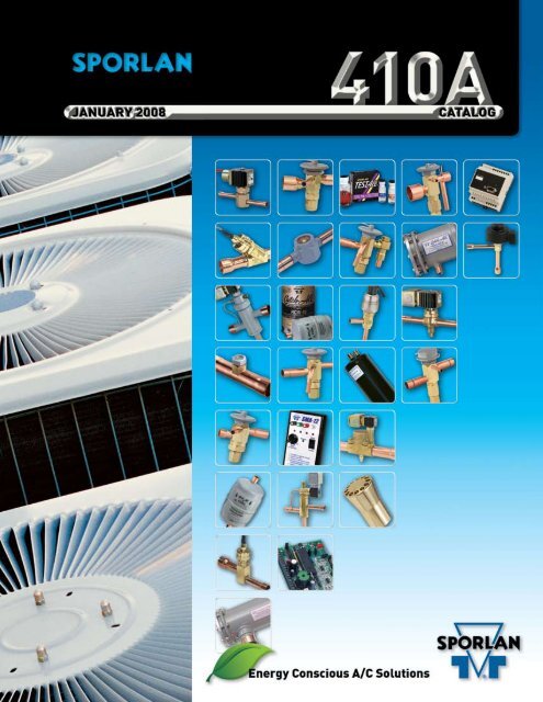
CATALOG 410A — Page 1<br />
Condensed Catalog 410A January 2008<br />
This condensed catalog contains product specifically for R-410A<br />
applications. By including a minimum of engineering information<br />
we are able to provide a concise reference to pertinent data<br />
and specifications on Sporlan R-410A products. For additional<br />
engineering information, a complete Sporlan Catalog or CD, please<br />
contact your nearest Sporlan Sales Office, Authorized Sporlan Wholesaler<br />
or log on to www.sporlan.com.<br />
CONTENTS<br />
Page<br />
*For complete product information<br />
see Bulletin number listed below.<br />
Accumulators ............................................................ 29 40-10-7<br />
Acid Test Kits ............................................................. 32 40-10<br />
Auxiliary Side Connectors.................................................. 11 20-10<br />
Catch-All ® Filter-Driers Liquid & Suction Line ................................. 22 40-10<br />
Discharge Bypass Valves ................................................. 36 90-40<br />
Electronic Temperature Control Systems.................................... 40 100-9, 100-20, 100-20-1,<br />
........................................................................... 100-20-2, 100-40, 100-50-1<br />
........................................................................... 100-50-2, 100-50-3 &<br />
........................................................................... 100-60<br />
Head Pressure Control Valves ............................................. 33 90-30<br />
Pressure-Temperature Chart .............................................. 45 Form 10-135<br />
Refrigerant Distributors ................................................... 9 20-10<br />
Reversible Heat Pump Filter-Driers ......................................... 28 40-10<br />
See•All ® Moisture & Liquid Indicators ...................................... 31 70-10<br />
Solenoid Valves.......................................................... 12 30-10<br />
Suction Filters ........................................................... 32 80-10<br />
Thermostatic Expansion Valves ............................................. 2 10-9 & 10-10<br />
Three Way Heat Reclaim Valves ............................................ 19 30-20<br />
*To request individual Sporlan Product Bulletins, contact your nearest Sporlan Sales Office or Wholesaler, write Parker Hannifin, Sporlan Division, Washington,<br />
Missouri or visit our website at www.sporlan.com.<br />
Copyright 2008 by Parker Hannifin Corporation, Sporlan Division, Washington, Missouri<br />
FOR USE ON REFRIGERATION and/or AIR CONDITIONING SYSTEMS ONLY
Page 2 — CATALOG 410A<br />
Thermostatic Expansion Valves<br />
410A<br />
Sporlan offers thermostatic expansion valves in R-410A nominal<br />
capacities between 1/3 and 60 tons (1.17 and 210 kW). The models<br />
offered are externally equalized, have straight through or angle configuration,<br />
and ODF connections.<br />
The Sporlan refrigerant code for R-410A is the letter “Z”, which is<br />
found in valve nomenclature.<br />
The RZE models have the advantage of a balanced port construction,<br />
which makes them ideally suited for systems with a wide range of<br />
operating conditions.<br />
The RCZE model is similar to the RZE but has an internal check<br />
valve to allow refrigerant flow to bypass the expansion valve port in<br />
the reverse flow direction in heat pump systems. The integral check<br />
valve means fewer connections, easier installation, and increased<br />
reliability.<br />
The Sporlan TEVs designed for R-410A have replaceable thermostatic<br />
elements designed for the higher pressures associated with R-410A.<br />
Replaceable thermostatic elements are designated by:<br />
KT – 45 – ZGA<br />
Kit Element Size Charge<br />
ZGA – Has similar performance to the VGA charge used in R-22 or<br />
NGA charge used in R-407C systems. The constituents and heavy<br />
thermal ballasts in the charge provide excellent anti-hunt characteristics<br />
by dampening the valve in the opening direction. The maximum<br />
operating pressure or MOP of this charge is not as defined as the<br />
ZCP200 charge, an alternate charge for R-410A air conditioning and<br />
heat pump applications.<br />
ZCP200 – Has similar performance to the VCP100 charge used in<br />
R-22 systems or the NCP100 charge used in R-407C systems. The<br />
maximum operating pressure or MOP of this charge takes effect<br />
around 66°F (19°C) evaporator temperature. The ZCP200 charge has a<br />
mild thermal ballast that dampens the valve in the opening direction.<br />
Contact the nearest Sporlan sales office if you have an application that<br />
requires a valve or charge that is not listed.<br />
VALVE TYPE<br />
CONNECTIONS - Inches<br />
Inlet<br />
Outlet<br />
EXTERNAL<br />
EQUALIZER<br />
VALVE DESCRIPTION AND APPLICATION<br />
RZE<br />
RCZE<br />
3/8 ODF<br />
1/2 ODF<br />
5/8 ODF<br />
7/8 ODF<br />
3/8 ODF<br />
1/2 ODF<br />
Chatleff<br />
3/8 ODF<br />
1/2 ODF<br />
5/8 ODF<br />
7/8 ODF<br />
1-1/8 ODF<br />
1-3/8 ODF<br />
3/8 ODF<br />
1/2 ODF<br />
5/8 ODF<br />
Chatleff<br />
1/4” ODF<br />
or<br />
1/8” ODF<br />
Capillary<br />
Tube Lengths<br />
Available<br />
With<br />
OR Without<br />
1/4” SAE<br />
Flare Nut<br />
Small brass body valve available with either angle<br />
style or straight through connection pattern. RZE<br />
valves are available both externally adjustable and<br />
non-adjustable. The RZE has a balanced port construction,<br />
which makes it ideal for applications with a<br />
wide range of operating conditions. May be applied in<br />
bi-directional applications.<br />
In addition to the features described above for the<br />
RZE valve, the RCZE has a built-in check valve to<br />
allow bypass flow in the reverse direction. This feature<br />
makes this valve type ideally suited for heat pump<br />
applications. RCZE valves are available both externally<br />
adjustable and non-adjustable.<br />
O<br />
7/8 ODF<br />
1-1/8 ODF<br />
1-1/8 ODF<br />
1-3/8 ODF<br />
1-5/8 ODF<br />
1/4” ODF<br />
Brass bar body, externally adjustable valve. Inlet has<br />
a permanent 12 mesh strainer. This valve features a<br />
balanced port construction, and it is suitable for both<br />
air conditioning and refrigeration applications.<br />
SBQE<br />
3/8 ODF<br />
90° Angle Inlet<br />
1/2 ODF<br />
1/4” ODF<br />
Pointed<br />
Toward<br />
Bottom Cap<br />
Features ODF solder connections and a forged brass<br />
inlet fitting with a removable 100 mesh strainer which<br />
can be cleaned and/or replaced without removing the<br />
valve from the line. May be applied in bi-directional<br />
applications.<br />
EBQE<br />
3/8 ODF<br />
1/2 ODF<br />
Straight Through<br />
1/2 ODF<br />
5/8 ODF<br />
7/8 ODF<br />
Features extended ODF connections. A 100 mesh insert<br />
strainer is provided with the valve. May be applied in<br />
bi-directional applications.<br />
Note: Not all fitting combinations are available.
Thermostatic Expansion Valves<br />
CATALOG 410A — Page 3<br />
410A<br />
Type RZE<br />
Knife Edge Joint<br />
Standard Cap Tube Length 30 in. (76 cm)<br />
1.94”<br />
49 mm<br />
Cap Tube<br />
30”<br />
76 cm<br />
The RZE valve is an externally adjustable<br />
balance ported TEV designed for R-410A air<br />
conditioning applications. This makes the RZE<br />
valve an excellent replacement for all OEM BI<br />
and BBI valves as well as other applications<br />
Type<br />
RZE<br />
requiring a R-410A expansion valve such as I and RI valves. The RZE<br />
valve utilizes the KT-45 element design for the higher pressures of<br />
R-410A. This valve may also be applied in bi-directional applications.<br />
3.53”<br />
90 mm<br />
2.17”<br />
55 mm<br />
1.83”<br />
46 mm<br />
D<br />
Dimensions<br />
Connections<br />
VALVE<br />
TYPE<br />
RZE-<br />
1, 1-1/2 & 2*<br />
RZE-<br />
3, 4, 5, 6 & 8<br />
FITTING SIZE<br />
Inches<br />
Inches<br />
mm<br />
A B A B<br />
3/8 ODF 1.69 1.35 42.9 34.3<br />
1/2 ODF 1.75* 1.35 44.5 34.3<br />
5/8 ODF – 1.43 – 36.3<br />
3/8 ODF 1.69 – 42.9 34.3<br />
1/2 ODF 1.75 1.35 44.5 34.3<br />
5/8 ODF 1.33 1.43 33.8 36.3<br />
7/8 ODF – 2.01 – 51.1<br />
RZE-8 7/8 ODF Ext. – 2.41 – 61.2<br />
5/8 ODF 1.50 – 38.1 –<br />
7/8 ODF 2.08 – 52.8 –<br />
RZE- 5/8 ODF Ext. – 2.16 62.2 54.9<br />
12-1/2 & 15 7/8 ODF Ext. – 2.51 – 63.8<br />
1-1/8 ODF Ext. – 2.51 – 63.8<br />
1-3/8 ODF Ext. – 3.02 – 76.7<br />
*1/2 ODF inlet available on 2 ton valves only.<br />
Bulb Sizes<br />
Top View<br />
A<br />
1/4” ODF<br />
1.83”<br />
46 mm<br />
THERMOSTATIC Inches mm<br />
CHARGE C D C D<br />
ZCP200 0.50 3.00 13 76<br />
ZGA 0.75 2.00 19 51<br />
B<br />
30°<br />
C<br />
Capacities<br />
Tons n psi n °F kW n bar n °C<br />
VALVE<br />
TYPE<br />
NOMINAL<br />
CAPACITY<br />
(Tons)<br />
EVAPORATOR TEMPERATURE °F<br />
40 20 0<br />
PRESSURE DROP ACROSS VALVE (psi)<br />
160 200 200<br />
RZE-1-GA 1 1.2 1.3 1.2<br />
RZE-1-1/2-GA 1-1/2 2.1 2.3 2.0<br />
RZE-2-GA 2 2.7 3.0 2.7<br />
RZE-3-GA 3 3.8 4.1 3.7<br />
RZE-4-GA 4 5.0 5.4 4.9<br />
RZE-5-GA 5 5.9 6.5 5.8<br />
RZE-6-GA 6 7.1 7.8 6.3<br />
RZE-8-GA 8 9.5 10.4 9.3<br />
RZE-12-1/2-GA 12-1/2 12.3 13.5 12.1<br />
RZE-15-GA 15 14.3 15.7 14.0<br />
LIQUID TEMPERATURE ENTERING TEV °F<br />
40 50 60 70 80 90 100 110 120 130 140<br />
CORRECTION FACTOR, CF LIQUID TEMPERATURE<br />
1.39 1.31 1.23 1.17 1.12 1.06 1.00 0.94 0.88 0.82 0.76<br />
VALVE<br />
TYPE<br />
NOMINAL<br />
CAPACITY<br />
(kW)<br />
EVAPORATOR TEMPERATURE °C<br />
5 -5 -15<br />
PRESSURE DROP ACROSS VALVE (bar)<br />
11 14 14<br />
RZE-1-GA 4.20 4.20 4.64 4.25<br />
RZE-1-1/2-GA 7.35 7.35 8.11 7.44<br />
RZE-2-GA 9.66 9.66 10.7 9.77<br />
RZE-3-GA 13.4 13.4 14.8 13.6<br />
RZE-4-GA 17.6 17.6 19.5 17.8<br />
RZE-5-GA 21.0 21.0 23.2 21.2<br />
RZE-6-GA 25.2 25.2 27.8 23.7<br />
RZE-8-GA 33.6 33.6 37.1 34.0<br />
RZE-12-1/2-GA 43.8 43.8 48.4 44.3<br />
RZE-15-GA 50.8 50.8 56.1 51.4<br />
LIQUID TEMPERATURE ENTERING TEV °C<br />
5 10 15 20 25 30 35 40 45 50 55 60<br />
CORRECTION FACTOR, CF LIQUID TEMPERATURE<br />
1.46 1.39 1.32 1.25 1.18 1.11 1.04 0.97 0.89 0.81 0.72 0.62<br />
EVAPORATOR<br />
TEMPERATURE<br />
°F<br />
PRESSURE DROP ACROSS TEV (psi)<br />
80 120 160 200 240 280 320 360<br />
CORRECTION FACTOR, CF PRESSURE DROP<br />
0° 0.71 0.87 1.00 1.12 1.22 1.32 1.41 1.50<br />
20° 0.63 0.77 0.89 1.00 1.10 1.18 1.26 1.34<br />
40° 0.63 0.77 0.89 1.00 1.10 1.18 1.26 1.34<br />
EVAPORATOR<br />
TEMPERATURE<br />
°C<br />
PRESSURE DROP ACROSS TEV (bar)<br />
8 10 11 12 13 14 16 18 20<br />
CORRECTION FACTOR, CF PRESSURE DROP<br />
5° 0.85 0.95 1.00 1.04 1.09 1.13 1.21 1.28 1.35<br />
-5° 0.76 0.85 0.89 0.93 0.96 1.00 1.07 1.13 1.20<br />
-15° 0.76 0.85 0.89 0.93 0.96 1.00 1.07 1.13 1.20
Page 4 — CATALOG 410A<br />
Thermostatic Expansion Valves<br />
410A<br />
Type RCZE<br />
Knife Edge Joint<br />
Standard Cap Tube Length 30 in. (76 cm)<br />
1.94”<br />
49 mm<br />
Cap Tube<br />
30”<br />
76 cm<br />
The RCZE valve is an externally adjustable<br />
balance ported TEV with an internal<br />
check valve for heat pump applications. This<br />
makes the RCZE valve an excellent replacement<br />
for all OEM CBI and CBBI valves as<br />
Type<br />
RCZE<br />
well as other applications requiring a R-410A expansion valve on heat<br />
pumps. The RCZE valve may also be used on air conditioning (cooling<br />
only) applications. This allows you to reduce inventory to also<br />
replace the I, RI, BI and BBI valves. The RCZE valves utilize the<br />
KT-45 element design for the higher pressures of R-410A systems.<br />
3.66”<br />
93 mm<br />
2.30”<br />
58 mm<br />
1.81”<br />
46 mm<br />
D<br />
Dimensions<br />
Connections<br />
VALVE<br />
TYPE<br />
RCZE-<br />
1, 1-1/2 & 2<br />
RCZE-<br />
3, 4, 5 & 6<br />
FITTING SIZE<br />
Inches<br />
Inches<br />
mm<br />
A B A B<br />
3/8 ODF 1.92 1.45 48.8 36.8<br />
1/2 ODF 1.98* 1.45 50.3 36.8<br />
5/8 ODF – 1.53 – 38.9<br />
3/8 ODF 1.92 1.45 48.8 36.8<br />
1/2 ODF 1.98 1.45 50.3 36.8<br />
5/8 ODF – 1.53 – 38.9<br />
RCZE Chatleff Fitting 1.89 1.71 48.0 43.4<br />
*1/2 ODF inlet available on 2 ton valves only.<br />
Chatleff<br />
Fitting Option<br />
A<br />
B<br />
Top View<br />
1/4” ODF<br />
1.90”<br />
48 mm<br />
C<br />
30°<br />
Bulb Sizes<br />
THERMOSTATIC Inches mm<br />
CHARGE C D C D<br />
ZCP200 0.50 3.00 13 76<br />
ZGA 0.75 2.00 19 51<br />
Capacities<br />
Tons n psi n °F kW n bar n °C<br />
VALVE<br />
TYPE<br />
NOMINAL<br />
CAPACITY<br />
(Tons)<br />
EVAPORATOR TEMPERATURE °F<br />
40 20 0<br />
PRESSURE DROP ACROSS VALVE (psi)<br />
160 200 200<br />
RCZE-1-GA 1 1.2 1.3 1.2<br />
RCZE-1-1/2-GA 1-1/2 2.1 2.3 2.0<br />
RCZE-2-GA 2 2.7 3.0 2.7<br />
RCZE-3-GA 3 3.8 4.1 3.7<br />
RCZE-4-GA 4 5.0 5.4 4.9<br />
RCZE-5-GA 5 5.9 6.5 5.8<br />
RCZE-6-GA 6 7.1 7.8 6.3<br />
VALVE<br />
TYPE<br />
NOMINAL<br />
CAPACITY<br />
(kW)<br />
EVAPORATOR TEMPERATURE °C<br />
5 -5 -15<br />
PRESSURE DROP ACROSS VALVE (bar)<br />
11 14 14<br />
RCZE-1-GA 4.20 4.20 4.64 4.25<br />
RCZE-1-1/2-GA 7.35 7.35 8.11 7.44<br />
RCZE-2-GA 9.66 9.66 10.7 9.77<br />
RCZE-3-GA 13.4 13.4 14.8 13.6<br />
RCZE-4-GA 17.6 17.6 19.5 17.8<br />
RCZE-5-GA 21.0 21.0 23.2 21.2<br />
RCZE-6-GA 25.2 25.2 27.8 23.7<br />
LIQUID TEMPERATURE ENTERING TEV °F<br />
40 50 60 70 80 90 100 110 120 130 140<br />
CORRECTION FACTOR, CF LIQUID TEMPERATURE<br />
1.39 1.31 1.23 1.17 1.12 1.06 1.00 0.94 0.88 0.82 0.76<br />
EVAPORATOR<br />
TEMPERATURE<br />
°F<br />
PRESSURE DROP ACROSS TEV (psi)<br />
80 120 160 200 240 280 320 360<br />
CORRECTION FACTOR, CF PRESSURE DROP<br />
0° 0.71 0.87 1.00 1.12 1.22 1.32 1.41 1.50<br />
20° 0.63 0.77 0.89 1.00 1.10 1.18 1.26 1.34<br />
40° 0.63 0.77 0.89 1.00 1.10 1.18 1.26 1.34<br />
LIQUID TEMPERATURE ENTERING TEV °C<br />
5 10 15 20 25 30 35 40 45 50 55 60<br />
CORRECTION FACTOR, CF LIQUID TEMPERATURE<br />
1.46 1.39 1.32 1.25 1.18 1.11 1.04 0.97 0.89 0.81 0.72 0.62<br />
EVAPORATOR<br />
TEMPERATURE<br />
°C<br />
PRESSURE DROP ACROSS TEV (bar)<br />
8 10 11 12 13 14 16 18 20<br />
CORRECTION FACTOR, CF PRESSURE DROP<br />
5° 0.85 0.95 1.00 1.04 1.09 1.13 1.21 1.28 1.35<br />
-5° 0.76 0.85 0.89 0.93 0.96 1.00 1.07 1.13 1.20<br />
-15° 0.76 0.85 0.89 0.93 0.96 1.00 1.07 1.13 1.20
Thermostatic Expansion Valves<br />
CATALOG 410A — Page 5<br />
410A<br />
Type O<br />
Knife Edge Joint<br />
Standard Cap Tube Length 5 Feet (1.5 m)<br />
Sporlan Type O Valve is a brass bar body,<br />
externally adjustable valve with ODF solder<br />
connections. The thermostatic element is Type O<br />
replaceable, and the inlet connection has a<br />
permanent 12 mesh strainer. This valve type features a balanced<br />
port construction, and it is designed for both air conditioning and<br />
refrigeration applications. A synthetic seating surface provides tight<br />
shut-off during sytem off periods.<br />
Dimensions<br />
Type O with Number 85 Element<br />
For use on 20 thru 35 Ton Valves<br />
This valve type has two body styles: a small body which provides<br />
capacities up to 35 tons (120 kW) R-410A, and a large body which<br />
extends capacities up to 60 tons (210 kW) R-410A.<br />
Refrigerant distributors that will mate directly to this valve are listed<br />
below. Refer to Sporlan Bulletin 20-10 for additional application<br />
information on this subject.<br />
Outlet Connections Distributors<br />
1-1/8” ODF 1115, 1116, 1655R<br />
1-3/8” ODF 1117, 1126, 1128, 1657R<br />
1-5/8” ODF 1125, 1127, 1143, 1659R<br />
Type O with Number 85-3 Element<br />
For use on 50 and 60 Ton Valves<br />
2.31”<br />
59 mm<br />
Cap Tube<br />
5’<br />
1.5 m<br />
2.31”<br />
59 mm<br />
Cap Tube<br />
5’<br />
1.5 m<br />
1.70”<br />
43 mm<br />
2.43”<br />
62 mm<br />
1.93”<br />
49 mm<br />
2.90”<br />
74 mm<br />
C<br />
4.14”<br />
105 mm<br />
C<br />
C<br />
D<br />
E<br />
5.52”<br />
140 mm<br />
C<br />
D<br />
E<br />
A<br />
B<br />
A<br />
B<br />
1/4” ODF External<br />
Equalizer<br />
Connection<br />
1.40”<br />
36 mm<br />
1/4“ ODF<br />
1/4” ODF External<br />
Equalizer<br />
Connection<br />
1.59”<br />
40 mm<br />
1/4“ ODF<br />
Top View<br />
Top View<br />
Connections<br />
STRAIGHT THRU<br />
ODF SOLDER<br />
Bulb Sizes<br />
THERMOSTATIC<br />
CHARGE<br />
Inches<br />
mm<br />
A B C A B C<br />
7/8 2.09 – 0.75 53 – 19<br />
1-1/8 2.21 2.23 0.91 56 57 23<br />
1-3/8 – 2.39 0.97 – 61 25<br />
Inches mm<br />
D E D E<br />
ZGA 0.75 2.00 19 51<br />
Connections<br />
STRAIGHT THRU<br />
ODF SOLDER<br />
Bulb Sizes<br />
THERMOSTATIC<br />
CHARGE<br />
Inches<br />
mm<br />
A B C A B C<br />
1-1/8 2.69 – 0.91 68 – 23<br />
1-3/8 – 2.84 0.97 – 72 25<br />
1-5/8 – 3.12 1.09 – 79 28<br />
Inches mm<br />
D E D E<br />
ZGA 0.75 2.00 19 51
Page 6 — CATALOG 410A<br />
Thermostatic Expansion Valves<br />
410A<br />
Capacities<br />
Tons n psi n °F kW n bar n °C<br />
VALVE<br />
TYPE<br />
NOMINAL<br />
CAPACITY<br />
(Tons)<br />
EVAPORATOR TEMPERATURE °F<br />
40 20 0<br />
PRESSURE DROP ACROSS VALVE (psi)<br />
160 200 200<br />
OZE-20 20 19.7 21.6 20.4<br />
OZE-25 25 23.7 25.9 24.5<br />
OZE-35 35 32.6 35.6 33.6<br />
OZE-50 50 49.3 54.0 51.0<br />
OZE-60 60 59.2 64.8 61.2<br />
VALVE<br />
TYPE<br />
NOMINAL<br />
CAPACITY<br />
(kW)<br />
EVAPORATOR TEMPERATURE °C<br />
5 -5 -15<br />
PRESSURE DROP ACROSS VALVE (bar)<br />
11 14 14<br />
OZE-20 70 70.1 77.4 73.7<br />
OZE-25 84 84.1 92.8 88.5<br />
OZE-35 116 116.0 128.0 122.0<br />
OZE-50 175 175.0 193.0 184.0<br />
OZE-60 210 210.0 232.0 221.0<br />
LIQUID TEMPERATURE ENTERING TEV °F<br />
40 50 60 70 80 90 100 110 120 130 140<br />
CORRECTION FACTOR, CF LIQUID TEMPERATURE<br />
1.39 1.31 1.23 1.17 1.12 1.06 1.00 0.94 0.88 0.82 0.76<br />
EVAPORATOR<br />
TEMPERATURE<br />
°F<br />
PRESSURE DROP ACROSS TEV (psi)<br />
80 120 160 200 240 280 320 360<br />
CORRECTION FACTOR, CF PRESSURE DROP<br />
0° 0.71 0.87 1.00 1.12 1.22 1.32 1.41 1.50<br />
20° 0.63 0.77 0.89 1.00 1.10 1.18 1.26 1.34<br />
40° 0.63 0.77 0.89 1.00 1.10 1.18 1.26 1.34<br />
LIQUID TEMPERATURE ENTERING TEV °C<br />
5 10 15 20 25 30 35 40 45 50 55 60<br />
CORRECTION FACTOR, CF LIQUID TEMPERATURE<br />
1.46 1.39 1.32 1.25 1.18 1.11 1.04 0.97 0.89 0.81 0.72 0.62<br />
EVAPORATOR<br />
TEMPERATURE<br />
°C<br />
PRESSURE DROP ACROSS TEV (bar)<br />
8 10 11 12 13 14 16 18 20<br />
CORRECTION FACTOR, CF PRESSURE DROP<br />
5° 0.85 0.95 1.00 1.04 1.09 1.13 1.21 1.28 1.35<br />
-5° 0.76 0.85 0.89 0.93 0.96 1.00 1.07 1.13 1.20<br />
-15° 0.76 0.85 0.89 0.93 0.96 1.00 1.07 1.13 1.20
Thermostatic Expansion Valves<br />
CATALOG 410A — Page 7<br />
410A<br />
Type EBQE & SBQE<br />
Balanced Port Replaceable Cartridge Style<br />
Knife Edge Joint<br />
Standard Cap Tube Length 5 Feet (1.5 m)<br />
Sporlan Types SBQE & EBQE are small brass bar body valves<br />
with extended ODF solder connections and the same balanced port<br />
construction as the Type BF valve. Both valves have replaceable<br />
thermostatic elements. The Type EBQE has a 100 mesh insert strainer.<br />
The Type SBQE has a 100 mesh removable strainer that can be cleaned<br />
and/or replaced while the valve is still soldered to the system tubing.<br />
Type EBQE<br />
Type SBQE<br />
The balanced port construction makes these valves ideally suited for<br />
R-410A applications with varying pressure drop across the valve. The<br />
EBQE and SBQE may also be applied in bi-directional applications.<br />
Dimensions<br />
Type EBQE with Number 45 Element<br />
1.94”<br />
49 mm<br />
Cap Tube<br />
5’<br />
1.5 m<br />
Type SBQE with Number 45 Element<br />
Removable<br />
Strainer<br />
P/N 3427-000<br />
1.94”<br />
49 mm<br />
Cap Tube<br />
5’<br />
1.5 m<br />
3.93”<br />
100 mm<br />
3.93”<br />
100 mm<br />
2.53”<br />
64 mm<br />
3/8 ODF<br />
Insert Strainer<br />
P/N 877-003<br />
1/2 ODF<br />
Insert Strainer<br />
P/N 877-004<br />
2.02”<br />
51 mm<br />
D<br />
2.53”<br />
64 mm<br />
.84”<br />
21mm<br />
2.02”<br />
51 mm<br />
D<br />
A<br />
B<br />
C<br />
1.39”<br />
35 mm<br />
2.48”<br />
63 mm<br />
C<br />
60°<br />
60°<br />
Top View<br />
1.87”<br />
47 mm<br />
Top View<br />
1.87”<br />
47 mm<br />
Connections<br />
FITTING SIZE<br />
Inches<br />
Bulb Sizes<br />
Inches<br />
mm<br />
A B A B<br />
3/8 2.50 – 64 –<br />
1/2 2.42 2.48 61 63<br />
5/8 – 2.48 – 63<br />
7/8 – 2.39 – 61<br />
THERMOSTATIC<br />
CHARGE<br />
Inches mm<br />
C D C D<br />
ZCP200 0.50 3.00 13 76<br />
ZGA 0.75 2.00 19 51<br />
Connections<br />
Only available with 3/8” ODF Inlet and 1/2” ODF Outlet.<br />
Bulb Sizes<br />
THERMOSTATIC<br />
CHARGE<br />
Inches mm<br />
C D C D<br />
ZCP200 0.50 3.00 13 76<br />
ZGA 0.75 2.00 19 51
Page 8 — CATALOG 410A<br />
Thermostatic Expansion Valves<br />
410A<br />
Specifications<br />
TYPE EBQE<br />
EXTENDED<br />
ODF SOLDER<br />
TYPE SBQE<br />
EXTENDED<br />
ODF SOLDER<br />
(with replaceable<br />
strainer)<br />
CARTRIDGE<br />
CODE<br />
(Port Size)<br />
NOMINAL<br />
CAPACITY<br />
RANGE<br />
CONNECTIONS - Inches<br />
BOLD figures are standard<br />
and will be furnished<br />
unless otherwise specified.<br />
EXTERNAL EQUALIZER TONS kW INLET X OUTLET EXTERNAL EQUALIZER<br />
EBQE-AAA<br />
EBQE-AA<br />
EBQE-A<br />
SBQE-AAA<br />
SBQE-AA<br />
SBQE-A<br />
AAA<br />
AA<br />
A<br />
1/4 – 1/3<br />
1/2 – 3/4<br />
1 – 1-3/4<br />
0.88 – 1.17<br />
1.76 – 2.64<br />
3.52 – 6.15<br />
EBQE<br />
3/8 x 1/2 ODF<br />
1/2 x 5/8 ODF<br />
1/2 x 7/8 ODF<br />
Straight Thru<br />
EBQE-B SBQE-B B 2 – 3-1/2 7.03 – 12.3<br />
EBQE-C SBQE-C C 4 – 6 14.1 – 21.1<br />
SBQE<br />
3/8 x 1/2 ODF<br />
90° Angle Inlet<br />
1/4” ODF<br />
Pointed Toward<br />
Bottom Cap<br />
Capacities<br />
Tons n psi n °F kW n bar n °C<br />
CARTRIDGE<br />
TYPE<br />
NOMINAL<br />
CAPACITY<br />
(Tons)<br />
EVAPORATOR TEMPERATURE °F<br />
40 20 0<br />
PRESSURE DROP ACROSS VALVE (psi)<br />
160 200 200<br />
AAA 1/3 0.419 0.458 0.4<br />
AA 2/3 0.899 0.981 0.857<br />
A 1-1/2 1.92 2.09 1.83<br />
B 3 3.36 3.66 3.20<br />
C 5-1/2 6.23 6.80 5.94<br />
CARTRIDGE<br />
TYPE<br />
NOMINAL<br />
CAPACITY<br />
(kW)<br />
EVAPORATOR TEMPERATURE °C<br />
5 -5 -15<br />
PRESSURE DROP ACROSS VALVE (bar)<br />
11 14 14<br />
AAA 1.47 1.47 1.62 1.46<br />
AA 3.15 3.15 3.48 3.14<br />
A 6.72 6.72 7.42 6.69<br />
B 11.8 11.8 13.0 11.7<br />
C 21.8 21.8 24.1 21.7<br />
LIQUID TEMPERATURE ENTERING TEV °F<br />
40 50 60 70 80 90 100 110 120 130 140<br />
CORRECTION FACTOR, CF LIQUID TEMPERATURE<br />
1.39 1.31 1.23 1.17 1.12 1.06 1.00 0.94 0.88 0.82 0.76<br />
EVAPORATOR<br />
TEMPERATURE<br />
°F<br />
PRESSURE DROP ACROSS TEV (psi)<br />
80 120 160 200 240 280 320 360<br />
CORRECTION FACTOR, CF PRESSURE DROP<br />
0° 0.71 0.87 1.00 1.12 1.22 1.32 1.41 1.50<br />
20° 0.63 0.77 0.89 1.00 1.10 1.18 1.26 1.34<br />
40° 0.63 0.77 0.89 1.00 1.10 1.18 1.26 1.34<br />
LIQUID TEMPERATURE ENTERING TEV °C<br />
5 10 15 20 25 30 35 40 45 50 55 60<br />
CORRECTION FACTOR, CF LIQUID TEMPERATURE<br />
1.46 1.39 1.32 1.25 1.18 1.11 1.04 0.97 0.89 0.81 0.72 0.62<br />
EVAPORATOR<br />
TEMPERATURE<br />
°C<br />
PRESSURE DROP ACROSS TEV (bar)<br />
8 10 11 12 13 14 16 18 20<br />
CORRECTION FACTOR, CF PRESSURE DROP<br />
5° 0.85 0.95 1.00 1.04 1.09 1.13 1.21 1.28 1.35<br />
-5° 0.76 0.85 0.89 0.93 0.96 1.00 1.07 1.13 1.20<br />
-15° 0.76 0.85 0.89 0.93 0.96 1.00 1.07 1.13 1.20
Distributors and Auxiliary Side Connectors<br />
CATALOG 410A — Page 9<br />
410A<br />
All Sporlan distributors are ready for service with R-410A. The following<br />
tables are provided for making selections based on procedure<br />
explained in Bulletin 20-10.<br />
Quick Reference<br />
CONNECTION SIZE<br />
Inches<br />
1/2 ODM<br />
5/8 ODM<br />
7/8 ODM<br />
TYPICAL TEV<br />
TYPES Q, W<br />
BI, BBI, CBI, CBBI,<br />
EBQ, R, RC, SBQ<br />
BI, BBI, CBI, CBBI,<br />
EBQ, R, RC<br />
BI, BBI, CBI, CBBI,<br />
EBQ, O, R<br />
1-1/8 ODM O, R<br />
1-3/8 ODM O, R<br />
1-5/8 ODM O<br />
Dimensions<br />
D<br />
A<br />
DISTRIBUTOR<br />
TYPE<br />
Q TEV models in italics are OEM type thermostatic expansion valves.<br />
W Thermostatic expansion valves used with refrigerant distributor must be externally equalized.<br />
1126<br />
MAXIMUM NUMBER OF CIRCUITS NOZZLE<br />
3/16 1/4 5/16 3/8 TYPE<br />
1613 6 4 – – PERM. –<br />
1616 8 6 4 – PERM. –<br />
D260 6 4 – – L –<br />
D262 9 6 4 – L –<br />
1651 ASC<br />
SIDE<br />
CONNECTION<br />
1620 6 4 – – J –<br />
1622 9 7 4 – J –<br />
1651(R) 7 5 – – J (R) 3/8 or 1/2 ODF<br />
1112 7 6 4 2 G –<br />
1113 12 8 6 4 G –<br />
1653(R) 12 9 6 4 G (R) 3/8 or 1/2 ODF<br />
1115 15 10 9 6 E –<br />
1116 20 15 – – E –<br />
1655 (R) 20 12 10 7 E (R) 1/2 or 5/8 ODF<br />
MATERIAL<br />
#360 BRASS<br />
1117 18 15 9 7 C –<br />
1126 24 18 15 12 C –<br />
1128 28 25 21 16 C –<br />
#377 BRASS<br />
1657(R) 26 18 14 11 C (R) 5/8 or 7/8 ODF #360 BRASS<br />
1125 28 24 20 16 A – #377 BRASS<br />
1127 37 30 26 20 A –<br />
1143 40 36 30 24 A – #360 BRASS<br />
1659(R) 32 24 18 14 A (R) 7/8 or 1-1/8 ODF<br />
A<br />
C<br />
B<br />
C<br />
B<br />
Specifications<br />
D<br />
NUMBER OF<br />
CIRCUITS &<br />
TUBING SIZES<br />
AVAILABLE<br />
NOZZLE<br />
ORIFICE<br />
NUMBERS<br />
AVAILABLE<br />
NOZZLE &<br />
RETAINER<br />
RING SIZE<br />
INLET<br />
CONNECTION<br />
Inches<br />
DISTRIBUTOR<br />
DIMENSIONS<br />
Inches<br />
mm<br />
A B C D A B C D<br />
Type D260 Net Weight - Approximately 2 oz. (60 g)<br />
2 to 6 3/16”<br />
1/9 thru 8 L<br />
2 to 4 1/4”<br />
1/2 ODM<br />
Solder<br />
1.96 0.81<br />
.497<br />
.503<br />
0.82 49.8 21<br />
12.6<br />
12.8<br />
21<br />
Type D262 Net Weight - Approximately 3 oz. (80 g)<br />
7 to 9 3/16”<br />
5 to 6 1/4” 1/9 thru 8 L<br />
2 to 4 5/16”<br />
1/2 ODM<br />
Solder<br />
2.44 1.00<br />
.497<br />
.503<br />
0.81 62.0 25.4<br />
12.6<br />
12.8<br />
21<br />
Type 1613 Net Weight - Approximately - Approximately 2 oz. (60 g)<br />
2 to 7 5/32”<br />
1/2 ODM<br />
2 to 6 3/16” 1/2 thru 5 PERM.<br />
Solder<br />
2 to 4 1/4”<br />
1.17 0.81<br />
.498<br />
.500<br />
0.50 29.7 21<br />
12.6<br />
12.7<br />
13<br />
Type 1616 Net Weight - Approximately - Approximately 3 oz. (80 g)<br />
8 to 10 5/32”<br />
7 to 8 3/16”<br />
1/2 ODM<br />
1/2 thru 5 PERM.<br />
5 to 6 1/4”<br />
Solder<br />
2 to 4 5/16”<br />
1.55 1.00<br />
.498<br />
.500<br />
0.50 39.4 25.4<br />
12.6<br />
12.7<br />
13<br />
Type 1620 Net Weight - Approximately 2 oz. (60 g)<br />
2 to 6 3/16”<br />
2 to 4 1/4”<br />
1/9 thru 8 J<br />
5/8 ODM<br />
Solder<br />
1.14 0.81<br />
.623<br />
.625<br />
0.69 29.0 21<br />
15.8<br />
15.9<br />
18
Page 10 — CATALOG 410A<br />
Distributors and Auxiliary Side Connectors<br />
410A<br />
Specifications<br />
NUMBER OF<br />
CIRCUITS &<br />
TUBING SIZES<br />
AVAILABLE<br />
NOZZLE<br />
ORIFICE<br />
NUMBERS<br />
AVAILABLE<br />
NOZZLE &<br />
RETAINER<br />
RING SIZE<br />
INLET<br />
CONNECTION<br />
Inches<br />
DISTRIBUTOR<br />
DIMENSIONS<br />
Inches<br />
mm<br />
A B C D A B C D<br />
Type 1622 Net Weight - Approximately 3 oz. (80 g)<br />
7 to 9 3/16”<br />
5 to 7 1/4” 1/9 thru 8 J<br />
2 to 4 5/16”<br />
5/8 ODM<br />
Solder<br />
1.63 1.00<br />
.623<br />
.625<br />
0.63 41.4 25.4<br />
15.8<br />
15.9<br />
16<br />
Type 1112 Net Weight - Approximately 4 oz. (110 g)<br />
5 to 7 3/16”<br />
4 to 6 1/4”<br />
1/6 thru 20 G<br />
2 to 4 5/16”<br />
2 3/8”<br />
7/8 ODM<br />
Solder<br />
1.72 0.91<br />
.873<br />
.875<br />
1.00 43.7 23<br />
22.2<br />
+/–<br />
0.03<br />
25.4<br />
Type 1113 Net Weight - Approximately 5 oz. (140 g)<br />
8 to 12 3/16”<br />
7 to 8 1/4”<br />
1/6 thru 20 G<br />
5 to 6 5/16”<br />
3 to 4 3/8”<br />
7/8 ODM<br />
Solder<br />
1.78 1.16<br />
.873<br />
.875<br />
0.88 45.2 29.5<br />
22.2<br />
+/–<br />
0.03<br />
22<br />
Type 1115 Net Weight - Approximately 9 oz. (250 g)<br />
11 to 15 3/16”<br />
9 to 10 1/4”<br />
2 thru 30 E<br />
7 to 9 5/16”<br />
5 to 6 3/8”<br />
1-1/8 ODM<br />
Solder<br />
2.44 1.50<br />
1.123<br />
1.125<br />
1.12 62.0 38.1<br />
28.52<br />
28.58<br />
28.4<br />
Type 1116 Net Weight - Approximately 9 oz. (250 g)<br />
16 to 20 3/16”<br />
11 to 15 1/4”<br />
2 thru 30 E<br />
1-1/8 ODM<br />
Solder<br />
2.44 1.75<br />
1.123<br />
1.125<br />
1.12 62.0 44.4<br />
28.52<br />
28.58<br />
28.4<br />
Type 1117 Net Weight - Approximately 1 lb. (450 g)<br />
16 to 18 3/16”<br />
11 to 15 1/4”<br />
3 thru 50 C<br />
9 5/16”<br />
7 3/8”<br />
1-3/8 ODM<br />
Solder<br />
2.56 1.75<br />
1.373<br />
1.375<br />
1.31 65.0 44.4<br />
34.87<br />
34.92<br />
33.3<br />
Type 1126 Net Weight - Approximately 1 lb., 6 oz. (620 g)<br />
19 to 24 3/16”<br />
15 to 18 1/4”<br />
1-3/8 ODM<br />
3 thru 50 C<br />
10 to 15 5/16”<br />
Solder<br />
8 to 12 3/8”<br />
2.81 2.38<br />
1.373<br />
1.375<br />
1.12 71.4 60.5<br />
34.87<br />
34.92<br />
28.4<br />
Type 1128 Net Weight - Approximately 1 lb., 10 oz. (740 g)<br />
25 to 28 3/16”<br />
19 to 25 1/4”<br />
1-3/8 ODM<br />
3 thru 50 C<br />
16 to 21 5/16”<br />
Solder<br />
13 to 16 3/8”<br />
3.12 3.00<br />
1.373<br />
1.375<br />
1.38 79.2 76.2<br />
34.87<br />
34.92<br />
35.1<br />
Type 1125 Net Weight - Approximately 1 lb., 14 oz. (850 g)<br />
25 to 28 3/16”<br />
19 to 24 1/4”<br />
1-5/8 ODM<br />
10 thru 50 A<br />
16 to 20 5/16”<br />
Solder<br />
13 to 16 3/8”<br />
3.12 3.00<br />
1.623<br />
1.625<br />
1.30 79.2 76.2<br />
41.22<br />
41.28<br />
33.0<br />
Type 1127 Net Weight - Approximately 2 lb., 4 oz. (1.0 kg)<br />
29 to 37 3/16”<br />
25 to 30 1/4”<br />
1-5/8 ODM<br />
10 thru 50 A<br />
21 to 26 5/16”<br />
Solder<br />
17 to 20 3/8”<br />
3.31 3.50<br />
1.623<br />
1.625<br />
1.28 84.1 88.9<br />
41.22<br />
41.28<br />
32.5<br />
Type 1143 Net Weight - Approximately 3 lb. (1.4 kg)<br />
29 to 40 3/16”<br />
31 to 36 1/4”<br />
10 thru 50 A<br />
27 to 30 5/16”<br />
21 to 24 3/8”<br />
1-5/8 ODM<br />
Solder<br />
3.69 4.00<br />
1.623<br />
1.625<br />
1.44 93.7 102<br />
41.22<br />
41.28<br />
36.6
Distributors and Auxiliary Side Connectors<br />
CATALOG 410A — Page 11<br />
410A<br />
Capacities Tons n psi n °F kW n bar n °C<br />
DISTRIBUTOR NOZZLE CAPACITIES<br />
NOZZLE<br />
EVAPORATOR TEMPERATURE °F<br />
NUMBER<br />
40 20 0 -20 -40<br />
1/9 0.16 0.13 0.10 0.08 0.07<br />
1/6 0.25 0.20 0.16 0.13 0.11<br />
1/4 0.40 0.31 0.25 0.21 0.17<br />
1/3 0.53 0.41 0.33 0.27 0.23<br />
1/2 0.73 0.57 0.46 0.37 0.31<br />
3/4 1.10 0.86 0.69 0.57 0.47<br />
1 1.47 1.15 0.92 0.76 0.64<br />
1-1/2 2.14 1.67 1.34 1.10 0.92<br />
2 2.93 2.30 1.84 1.51 1.27<br />
2-1/2 3.66 2.86 2.30 1.88 1.58<br />
3 4.39 3.44 2.76 2.26 1.90<br />
4 5.88 4.60 3.69 3.02 2.54<br />
5 7.25 5.67 4.55 3.73 3.13<br />
6 8.69 6.80 5.45 4.47 3.76<br />
8 10.5 8.19 6.57 5.39 4.53<br />
10 11.7 9.18 7.36 6.04 5.07<br />
12 14.5 11.3 9.09 7.46 6.26<br />
15 18.0 14.1 11.3 9.25 7.77<br />
17 20.1 15.7 12.6 10.3 8.69<br />
20 24.2 19.0 15.2 12.5 10.5<br />
25 30.5 23.8 19.1 15.7 13.2<br />
30 34.8 27.2 21.8 17.9 15.0<br />
35 41.9 32.8 26.3 21.5 18.1<br />
40 47.0 36.8 29.5 24.2 20.3<br />
50 60.9 47.7 38.2 31.3 26.3<br />
TUBE<br />
DIAMETER<br />
Inches<br />
DISTRIBUTOR CAPACITY PER TUBE (Tons)<br />
EVAPORATOR TEMPERATURE °F<br />
40 20 0 -20 -40<br />
3/16 0.41 0.31 0.23 0.18 0.14<br />
1/4 1.19 0.89 0.68 0.52 0.40<br />
5/16 2.41 1.82 1.38 1.06 0.82<br />
3/8 4.33 3.28 2.50 1.92 1.48<br />
LIQUID TEMPERATURE CORRECTION FOR NOZZLE AND TUBES °F<br />
50 60 70 80 90 100 110 120 130 140<br />
CORRECTION FACTOR, CF LIQUID TEMPERATURE<br />
2.10 1.83 1.59 1.37 1.17 1.00 0.85 0.72 0.61 0.52<br />
TUBE LENGTH CORRECTION FACTOR (Inches)<br />
12 18 24 30 36 42 48 54 60 66 72<br />
CORRECTION FACTOR, CF PRESSURE DROP<br />
1.36 1.16 1.07 1.00 0.95 0.90 0.86 0.82 0.79 0.76 0.73<br />
DISTRIBUTOR NOZZLE CAPACITIES<br />
NOZZLE<br />
EVAPORATOR TEMPERATURE °C<br />
NUMBER<br />
5 -5 -15 -30 -40<br />
1/9 0.57 0.46 0.37 0.29 0.24<br />
1/6 0.88 0.71 0.58 0.44 0.38<br />
1/4 1.42 1.14 0.93 0.71 0.61<br />
1/3 1.86 1.49 1.22 0.93 0.80<br />
1/2 2.57 2.06 1.68 1.29 1.10<br />
3/4 3.88 3.11 2.54 1.94 1.66<br />
1 5.20 4.16 3.40 2.60 2.22<br />
1-1/2 7.56 6.06 4.95 3.78 3.23<br />
2 10.4 8.31 6.79 5.18 4.44<br />
2-1/2 12.9 10.4 8.47 6.46 5.53<br />
3 15.5 12.4 10.2 7.76 6.64<br />
4 20.8 16.7 13.6 10.4 8.89<br />
5 25.7 20.5 16.8 12.8 11.0<br />
6 30.8 24.6 20.1 15.4 13.1<br />
8 37.1 29.7 24.2 18.5 15.8<br />
10 41.5 33.3 27.2 20.7 17.7<br />
12 51.3 41.1 33.5 25.6 21.9<br />
15 63.6 50.9 41.6 31.8 27.2<br />
17 71.1 57.0 46.5 35.5 30.4<br />
20 85.7 68.6 56.1 42.8 36.6<br />
25 108 86.3 70.5 53.8 46.1<br />
30 123 98.6 80.6 61.5 52.6<br />
35 148 119 96.9 74.0 63.3<br />
40 166 133 109 83.0 71.0<br />
50 216 173 141 108 92.1<br />
TUBE<br />
DIAMETER<br />
Inches<br />
DISTRIBUTOR CAPACITY PER TUBE (kW)<br />
EVAPORATOR TEMPERATURE °C<br />
5 -5 -15 -30 -40<br />
3/16 1.47 1.13 0.88 0.61 0.48<br />
1/4 4.28 3.28 2.55 1.77 1.40<br />
5/16 8.72 6.69 5.20 3.60 2.85<br />
3/8 15.8 12.1 9.40 6.51 5.15<br />
LIQUID TEMPERATURE CORRECTION FOR NOZZLE AND TUBES °C<br />
10 15 20 25 30 35 38 40 45 50 55 60<br />
CORRECTION FACTOR, CF LIQUID TEMPERATURE<br />
2.10 1.86 1.64 1.44 1.25 1.09 1.00 0.94 0.81 0.70 0.60 0.52<br />
TUBE LENGTH CORRECTION FACTOR (cm)<br />
30 45 60 75 90 105 120 135 150 165 180<br />
CORRECTION FACTOR, CF PRESSURE DROP<br />
1.36 1.16 1.07 1.00 0.95 0.90 0.86 0.82 0.79 0.76 0.73<br />
Auxiliary Side Connectors<br />
ASC-4-3, ASC-5-4, ASC-7-4, ASC-9-5, ASC-11-7, and ASC-13-9<br />
For proper distributor type, order by complete Sporlan type listed<br />
below. E.g., an 1126 distributor requires an ASC-11-7 Auxiliary<br />
Side Connector. Do not use an ASC that is smaller or larger than<br />
recommended. Bushing up or down at the outlet defeats the<br />
purpose of the internal nozzle tube extension. Do not use an ASC<br />
on distributors with permanent nozzles.<br />
A<br />
Inlet<br />
E<br />
D<br />
C<br />
F<br />
B<br />
Outlet<br />
Auxiliary<br />
Connection<br />
TYPE<br />
CONNECTION SIZES - Inches<br />
INLET<br />
ODM<br />
SOLDER<br />
OUTLET<br />
ODF<br />
SOLDER<br />
AUXILIARY<br />
ODF<br />
SOLDER<br />
USED WITH<br />
DISTRIBUTOR<br />
TYPE<br />
NOZZLE<br />
SIZE<br />
A<br />
(ODM)<br />
B<br />
(ODF)<br />
Inches<br />
C D E<br />
DIMENSIONS<br />
F<br />
(ODF)<br />
A<br />
(ODM)<br />
B<br />
(ODF)<br />
mm<br />
C D E<br />
ASC-4-3 1/2 1/2 3/8 D260, D262 L 1/2 1/2 1.75 0.85 1.04 3/8 12.7 12.7 44.4 22 26.4 9.52<br />
ASC-5-4 5/8 5/8 1/2 1620, 1622 J 5/8 5/8 1.88 0.95 1.25 1/2 15.9 15.9 47.8 24 31.8 12.7<br />
ASC-7-4 7/8 7/8 1/2 1112, 1113 G 7/8 7/8 2.25 1.06 1.38 1/2 22.2 22.2 51.2 26.9 35.1 12.7<br />
ASC-9-5 1-1/8 1-1/8 5/8 1115, 1116 E 1-1/8 1-1/8 2.81 1.47 1.62 5/8 28.6 28.6 71.4 37.3 41.1 15.9<br />
ASC-11-7 1-3/8 1-3/8 7/8 1117, 1126, 1128 C 1-3/8 1-3/8 3.53 1.89 2.19 7/8 34.9 34.9 89.7 48.0 55.6 22.2<br />
ASC-13-9 1-5/8 1-5/8 1-1/8 1125, 1127, 1143 A 1-5/8 1-5/8 3.72 1.83 2.75 1-1/8 41.3 41.3 94.5 46.5 69.8 28.6<br />
F<br />
(ODF)
Page 12 — CATALOG 410A<br />
Solenoid Valves<br />
410A<br />
Selection - Capacity Rating<br />
n Capacity, MOPD and Electrical specifications are required.<br />
All solenoid valves are tested and rated in accordance with A.R.I. Standard No. 760-2001.<br />
Liquid Capacity Selection Table Tons n psi n °F<br />
TYPE NUMBER<br />
CONNECTIONS PORT<br />
TONS OF REFRIGERATION<br />
“E” Series Extended Connections<br />
ODF SOLDER SIZE<br />
Without Manual Lift Stem With Manual Lift Stem<br />
Inches Inches<br />
PRESSURE DROP — psi*<br />
Normally Closed Normally Closed 1 2 3 4 5<br />
E5S130-HP – 3/8 0.150 1.52 2.16 2.66 3.08 3.45<br />
E6S130-HP ME6S130-HP 3/8<br />
– ME6S140-HP 1/2<br />
3/16 2.73 3.84 4.68 5.40 6.02<br />
E9S240-HP ME9S240-HP 1/2<br />
E9S250-HP – 5/8<br />
9/32 4.44 6.27 7.66 8.83 9.86<br />
E10S240-HP – 1/2 5/16 6.08 8.59 10.5 12.1 13.6<br />
E14S250-HP ME14S250-HP 5/8 7/16 8.64 12.2 14.9 17.2 19.2<br />
E19S270-HP ME19S270-HP 7/8 19/32 13.2 18.7 22.9 26.5 29.7<br />
E25S270-HP – 7/8<br />
E25S290-HP ME25S290-HP 1-1/8<br />
25/32 22.5 31.9 39.2 45.3 50.6<br />
– ME35S190-HP 1-1/8<br />
– ME35S1110-HP 1-3/8<br />
1 36.7 53.5 66.8 78.1 88.2<br />
E42S2130-HP – 1-5/8 1-5/16 69.6 98.4 120 139 156<br />
kW n bar n °C<br />
TYPE NUMBER<br />
CONNECTIONS PORT<br />
kW OF REFRIGERATION<br />
“E” Series Extended Connections<br />
ODF SOLDER SIZE<br />
Without Manual Lift Stem With Manual Lift Stem<br />
Inches<br />
mm<br />
PRESSURE DROP — bar*<br />
Normally Closed Normally Closed 0.07 0.1 0.2 0.3 0.4<br />
E5S130-HP – 3/8 3.8 5.37 6.44 9.16 11.3 13.0<br />
E6S130-HP ME6S130-HP 3/8<br />
– ME6S140-HP 1/2<br />
4.8 9.63 11.5 16.1 19.7 22.7<br />
E9S240-HP ME9S240-HP 1/2<br />
E9S250-HP – 5/8<br />
7.1 15.7 18.7 26.4 32.3 37.2<br />
E10S240-HP – 1/2 7.9 21.5 25.6 36.2 44.3 51.2<br />
E14S250-HP ME14S250-HP 5/8 11 39.5 36.4 51.4 62.9 72.6<br />
E19S270-HP ME19S270-HP 7/8 15 46.5 55.7 79.0 97 112<br />
E25S270-HP – 7/8<br />
E25S290-HP ME25S290-HP 1-1/8<br />
20 79.6 95.2 135 165 191<br />
– ME35S190-HP 1-1/8<br />
– ME35S1110-HP 1-3/8<br />
26 129 157 230 286 335<br />
E42S2130-HP – 1-5/8 34 246 294 415 508 587<br />
* Do not use below 1 psi (0.07 bar) pressure drop.<br />
Capacities based on 100°F (38°C) liquid temperature, 40°F (5°C) evaporator temperature. For other liquid line temperatures use liquid correction factors below. Maximum Operating<br />
Pressure Differential (MOPD) for the AC coil is 450 psid (31 bar). Maximum Rated Pressure (MRP) = 700 psig (48.3 bar).<br />
LIQUID TEMPERATURE CORRECTION FACTORS °F<br />
40 50 60 70 80 90 100 110 120 130 140<br />
CORRECTION FACTOR, CF LIQUID TEMPERATURE<br />
1.45 1.38 1.30 1.23 1.15 1.08 1.00 0.92 0.83 0.74 0.64<br />
LIQUID TEMPERATURE CORRECTION FACTORS °C<br />
5 10 15 20 25 30 35 40 45 50 55 60<br />
CORRECTION FACTOR, CF LIQUID TEMPERATURE<br />
1.45 1.38 1.32 1.25 1.18 1.11 1.04 0.97 0.90 0.82 0.74 0.64<br />
These factors include corrections for liquid refrigerant density and net refrigerating effect and are based on an average evaporator temperature of 40°F (5°C). For each 10°F (10°C)<br />
reduction in evaporating temperature, capacities are reduced by approximately 1-1/2% (2.7%).<br />
Discharge Gas Capacity - Tons n psi n °F kW n bar n °C<br />
VALVE<br />
SERIES<br />
DISCHARGE GAS CAPACITIES – Tons<br />
PRESSURE DROP ACROSS VALVE – psi<br />
2 5 10 25 50 100<br />
VALVE<br />
SERIES<br />
DISCHARGE GAS CAPACITIES – kW<br />
PRESSURE DROP ACROSS VALVE – bar<br />
0.15 0.3 0.7 1.5 4 7<br />
E5 0.54 0.86 1.22 2.26 3.02 3.75 E5 1.97 2.81 4.32 7.47 11.2 13.2<br />
B6 & E6 1.00 1.57 2.20 3.86 5.06 6.04 B6 & E6 3.66 5.14 7.80 12.8 18.7 21.3<br />
B9 & E9 1.61 2.54 3.58 5.67 7.72 10.1 B9 & E9 5.92 8.34 12.7 18.7 28.9 35.7<br />
B10 & E10 2.19 3.46 4.89 8.7 11.7 14.6 B10 & E10 8.04 11.4 17.3 28.7 43.3 51.7<br />
B14 & E14 3.13 4.93 6.96 11.9 16.1 20.7 B14 & E14 11.5 16.2 24.7 39.3 60.1 73.1<br />
B19 & E19 4.71 7.47 10.6 17.6 23.9 31.0 B19 & E19 17.3 24.5 37.5 58.1 89.4 109<br />
B25 & E25 8.07 12.8 18.1 28.1 38.2 49.5 B25 & E25 29.6 41.9 64.2 92.8 143 175<br />
E35 12.0 19.8 28.9 49.3 67.3 88.5 E35 44.3 64.6 103 162 252 313<br />
E42 25.1 39.6 56.0 82.1 111 144 E42 91.9 130 198 271 416 510<br />
* Minimum operating capacity is at 1 psi (0.07 bar) pressure drop.<br />
Capacities based on 100°F (38°C) condensing temperature, isentropic compression plus 50°F (28°C), 40°F (5°C) evaporator and 65°F (18.3°C) suction gas. For capacities at other<br />
conditions, consult Sporlan Division of Parker, Washington, MO.
Solenoid Valves<br />
Type E5 Series<br />
The E5 Series are hermetic solenoid valves with pilot operated disc<br />
construction. These valves may be mounted horizontally, on their<br />
side or in a vertical line.<br />
The E5 series solenoid valves feature extended solder type connections<br />
as standard. One important benefit to the user is that all valves<br />
in the “E5” series can be installed using either low or no silver content<br />
brazing alloy.<br />
CATALOG 410A — Page 13<br />
410A<br />
Ordering Instructions<br />
When ordering complete valves,<br />
specify Valve Type, Connections,<br />
Voltage and Cycles. When ordering<br />
Body Assembly, specify Valve Type E5S130-HP<br />
Type and Connections. When ordering<br />
Coil Assembly ONLY, specify Coil Type, Voltage and Cycles.<br />
Example: MKC-1 120/50-60.<br />
The MKC-l coil is Class “F” temperature rated and is provided as<br />
standard, therefore a high temperature coil is not required for discharge<br />
service.<br />
Dimensions<br />
VALVE<br />
SERIES<br />
Inches<br />
TYPE A B C<br />
D<br />
FITTING<br />
DEPTH<br />
ODF<br />
E5 E5S130-HP 4.56 0.53 2.48 0.31 0.23<br />
E<br />
OFFSET<br />
C<br />
1.56”<br />
40 mm Coil Removal<br />
Approved<br />
2.92”<br />
74 mm<br />
mm<br />
E5 E5S130-HP 116 13 63 8 6<br />
STANDARD<br />
VOLTS/CYCLES<br />
COIL RATINGS<br />
AC<br />
WATTS<br />
DC<br />
B<br />
E<br />
E5 Series<br />
A<br />
D<br />
24/50-60<br />
120/50-60<br />
208-240/50-60<br />
120-208-240/50-60<br />
10 15<br />
Specifications - MKC-1 Coil<br />
Tons n psi n °F kW n bar n °C<br />
VALVE<br />
SERIES<br />
TYPE<br />
CONNECTIONS<br />
ODF - Inches<br />
PORT<br />
SIZE<br />
Inches<br />
MOPD<br />
psi<br />
AC<br />
DC<br />
NOMINAL LIQUID<br />
CAPACITIES<br />
TONS of<br />
REFRIGERATION<br />
PRESSURE DROP<br />
3 psi<br />
VALVE<br />
SERIES<br />
TYPE<br />
CONNECTIONS<br />
ODF - Inches<br />
PORT<br />
SIZE<br />
mm<br />
MOPD<br />
bar<br />
AC<br />
DC<br />
NOMINAL LIQUID<br />
CAPACITIES<br />
kW of<br />
REFRIGERATION<br />
PRESSURE DROP<br />
0.2 bar<br />
E5 E5S130-HP 3/8 150 450 400 2.66<br />
n Maximum rated pressure 700 psi (48.3 bar).<br />
n Capacities based on 100°F (38°C) liquid temperature, 40°F (5°C) evaporator<br />
temperature. For other liquid line temperatures use liquid correction factors below.<br />
Maximum Operating Pressure Differential (MOPD) for the AC coil is 450 psid (31<br />
bar). Maximum Rated Pressure (MRP) = 700 psig (48.3 bar).<br />
E5 E5S130-HP 3/8 3.8 31 27.6 9.16<br />
n Dual voltage 4-wire coils, 120-208-240/50-60 are available at slight additional cost.<br />
For other voltages and cycles, consult Sporlan Division of Parker, Washington, MO.<br />
n Available with conduit boss, junction box, or DIN at no extra charge.<br />
n For capacity at other pressure drops, see page 12.
Page 14 — CATALOG 410A<br />
Solenoid Valves<br />
Type E6 Series<br />
The E6 Series are compact solenoid valves with pilot operated disc<br />
construction for refrigeration and air conditioning. These valves may<br />
be mounted horizontally, on their side or in a vertical line. They<br />
are suitable for suction line service because very low pressure differential,<br />
1 psi, is required for full operation.<br />
The Type E6 series solenoid valves feature extended solder type<br />
connections as standard. One important benefit to the user is that all<br />
valves in the “E6” series can be installed without disassembly using<br />
either low or no silver content brazing alloy.<br />
410A<br />
The MKC-l coil is Class “F” temperature<br />
rated and is provided as standard,<br />
therefore a high temperature coil is<br />
not required for discharge service.<br />
Type E6S130-HP<br />
Ordering Instructions<br />
When ordering complete valves, specify Valve Type, Connections,<br />
Voltage and Cycles. When ordering Body Assembly, specify Valve<br />
Type and Connections. When ordering Coil Assembly ONLY, specify<br />
Coil Type, Voltage and Cycles. Example: MKC-1 120/50-60.<br />
Dimensions<br />
VALVE<br />
SERIES<br />
TYPE A B* C<br />
D<br />
FITTING<br />
DEPTH<br />
ODF<br />
E<br />
OFFSET<br />
1.56”<br />
40 mm Coil Removal<br />
Approved<br />
2.92”<br />
74 mm<br />
Inches<br />
E6<br />
mm<br />
E6<br />
E6S130-HP 4.63<br />
0.31<br />
0.75 2.44<br />
E6S140-HP 5.00 0.38<br />
E6S130-HP 118<br />
7.9<br />
19 62<br />
E6S140-HP 127 9.7<br />
* Add 1.12” (28 mm) for valves with Manual Lift Stem.<br />
0.31<br />
7.9<br />
C<br />
*B<br />
E<br />
E6 Series<br />
A<br />
D<br />
STANDARD<br />
VOLTS/CYCLES<br />
COIL RATINGS<br />
AC<br />
WATTS<br />
DC<br />
1.64”<br />
42 mm<br />
24/50-60<br />
120/50-60<br />
208-240/50-60<br />
120-208-240/50-60<br />
10 15<br />
Optional 1/2”<br />
Conduit Boss<br />
Specifications - MKC-1 Coil<br />
Tons n psi n °F kW n bar n °C<br />
VALVE<br />
SERIES<br />
E6<br />
TYPE<br />
CONNECTIONS<br />
ODF - Inches<br />
E6S130-HP<br />
ME6S130-HP<br />
3/8<br />
ME6S140-HP 1/2<br />
PORT<br />
SIZE<br />
Inches<br />
MOPD<br />
psi<br />
NOMINAL LIQUID<br />
CAPACITIES<br />
TONS of<br />
REFRIGERATION<br />
n Maximum rated pressure 700 psi (48.3 bar).<br />
n Capacities based on 100°F (38°C) liquid temperature, 40°F (5°C) evaporator<br />
temperature. For other liquid line temperatures use liquid correction factors below.<br />
Maximum Operating Pressure Differential (MOPD) for the AC coil is 450 psid (31<br />
bar). Maximum Rated Pressure (MRP) = 700 psig (48.3 bar).<br />
AC<br />
DC<br />
PRESSURE DROP<br />
3 psi<br />
3/16 450 400 4.68<br />
VALVE<br />
SERIES<br />
E6<br />
TYPE<br />
CONNECTIONS<br />
ODF - Inches<br />
E6S130-HP<br />
ME6S130-HP<br />
3/8<br />
ME6S140-HP 1/2<br />
PORT<br />
SIZE<br />
mm<br />
MOPD<br />
bar<br />
NOMINAL LIQUID<br />
CAPACITIES<br />
kW of<br />
REFRIGERATION<br />
n Dual voltage 4-wire coils, 120-208-240/50-60 are available at slight additional cost.<br />
For other voltages and cycles, consult Sporlan Division of Parker, Washington, MO.<br />
n Available with conduit boss, junction box, or DIN at no extra charge.<br />
n For mounting holes and/or bracket information, see Bulletin 30-11<br />
n E6 series with mounting holes are NOT standard.<br />
n For capacity at other pressure drops, see page 12.<br />
AC<br />
DC<br />
PRESSURE DROP<br />
0.2 bar<br />
4.8 31 27.6 16.1
Solenoid Valves<br />
Types E9, E10, E14, E19 and E25 Series<br />
Types E9, E10, E14, E19 and E25 Series are compact solenoid valves<br />
with pilot operated disc construction for refrigeration and air conditioning.<br />
These valves may be mounted horizontally, on their side<br />
or in a vertical line. These valves are also suitable for suction line<br />
service because very low pressure differential, 1 psi, is required for<br />
full operation.<br />
The E9, E10, E14, E19 and E25 series solenoid valves feature<br />
extended solder type connections as standard. One important benefit<br />
to the user is that all valves in the “E9, E10, E14, E19 and E25<br />
series” series can be installed without disassembly using either low<br />
or no silver content brazing alloy.<br />
The MKC-2 and OMKC-2 coils are<br />
Class “F” temperature rated and are<br />
provided as standard, therefore a<br />
high temperature coil is not required<br />
for discharge service.<br />
CATALOG 410A — Page 15<br />
410A<br />
Type E14S250-HP<br />
Ordering Instructions<br />
When ordering complete valves, specify Valve Type, Connections,<br />
Voltage and Cycles. When ordering Body Assembly, specify Valve<br />
Type and Connections. When ordering Coil Assembly ONLY, specify<br />
Coil Type, Voltage and Cycles. Example: MKC-2 120/50-60;<br />
OMKC-2 120/50-60.<br />
Dimensions<br />
VALVE<br />
SERIES<br />
Inches<br />
TYPE A *B<br />
C D E<br />
NORMALLY<br />
CLOSED<br />
FITTING<br />
DEPTH<br />
ODF<br />
E9S230-HP 4.63 0.69 2.65 0.31 0.39<br />
E9 E9S240-HP 5.00 0.75 2.70 0.38 0.33<br />
E9S250-HP 6.50 0.69 2.74 0.50 0.31<br />
E10 E10S240-HP 5.00 0.85 3.13 0.38 0.38<br />
E14 E14S250-HP 6.88 0.46 3.26 0.50 –<br />
E19 E19S270-HP 7.13 0.81 3.41 0.75 –<br />
E25<br />
E25S270-HP 7.50 0.72 3.81 0.75 –<br />
E25S290-HP 8.50 0.72 3.81 0.91 –<br />
mm<br />
E9S230-HP 118 18.0 67 7.9 9.9<br />
E9 E9S240-HP 127 9.7 69 9.7 7.9<br />
E9S250-HP 165 12.7 69 13.0 9.7<br />
E10 E10S240-HP 127 9.7 80 9.7 9.7<br />
E14 E14S250-HP 175 11.7 83 13.0 –<br />
E19 E19S270-HP 181 21.0 87 19.0 –<br />
E25<br />
E25S270-HP 191 18.0 97 19.0 –<br />
E25S290-HP 216 18.0 97 23.0 –<br />
* Add 1.12” (28 mm) for valves with Manual Lift Stem.<br />
OFFSET<br />
C<br />
*B<br />
1.75”<br />
44 mm Coil Removal<br />
E10 Series<br />
E<br />
STANDARD<br />
VOLTS/CYCLES<br />
Approved<br />
Listed<br />
COIL RATINGS<br />
24/50-60<br />
120/50-60<br />
208-240/50-60<br />
120-208-240/50-60<br />
AC<br />
WATTS<br />
DC<br />
15 18<br />
A<br />
3.17”<br />
81 mm<br />
D<br />
1.89”<br />
48 mm<br />
Optional 1/2”<br />
Conduit Boss<br />
Specifications - MKC-2 and OMKC-2 Coil<br />
Tons n psi n °F kW n bar n °C<br />
VALVE<br />
SERIES<br />
TYPE<br />
CONNECTIONS<br />
ODF - Inches<br />
PORT<br />
SIZE<br />
Inches<br />
AC<br />
MOPD<br />
psi<br />
DC<br />
NOMINAL LIQUID<br />
CAPACITIES<br />
TONS of<br />
REFRIGERATION<br />
PRESSURE DROP<br />
3 psi<br />
E9S230-HP 3/8<br />
E9 E9S240-HP 1/2 9/32<br />
7.66<br />
E9S250-HP 5/8<br />
E10 E10S240-HP 1/2 5/16 10.5<br />
450 400<br />
E14 E14S250-HP 5/8 7/16 14.9<br />
E19 E19S270-HP 7/8 19/32 22.9<br />
E25<br />
E25S270-HP 7/8<br />
E25S290-HP 1-1/8<br />
25/32 39.2<br />
n Maximum rated pressure 700 psi (48.3 bar).<br />
n Capacities based on 100°F (38°C) liquid temperature, 40°F (5°C) evaporator<br />
temperature. For other liquid line temperatures use liquid correction factors below.<br />
Maximum Operating Pressure Differential (MOPD) for the AC coil is 450 psid (31<br />
bar). Maximum Rated Pressure (MRP) = 700 psig (48.3 bar).<br />
VALVE<br />
SERIES<br />
TYPE<br />
CONNECTIONS<br />
ODF - Inches<br />
PORT<br />
SIZE<br />
mm<br />
AC<br />
MOPD<br />
bar<br />
DC<br />
NOMINAL LIQUID<br />
CAPACITIES<br />
kW of<br />
REFRIGERATION<br />
PRESSURE DROP<br />
0.2 bar<br />
E9S230-HP 3/8<br />
E9 E9S240-HP 1/2 7.1<br />
32.3<br />
E9S250-HP 5/8<br />
E10 E10S240-HP 1/2 7.9 44.3<br />
31 27.6<br />
E14 E14S250-HP 5/8 11 62.9<br />
E19 E19S270-HP 7/8 15 97.0<br />
E25<br />
E25S270-HP 7/8<br />
E25S290-HP 1-1/8<br />
20 165<br />
n Dual voltage 4-wire coils, 120-208-240/50-60 are available at slight additional cost.<br />
For other voltages and cycles, consult Sporlan Division of Parker, Washington, MO.<br />
n Available with conduit boss, junction box, or DIN at no extra charge.<br />
n For capacity at other pressure drops, see page 12.
Page 16 — CATALOG 410A<br />
Solenoid Valves<br />
Types E35 Series<br />
Types E35 Series solenoid valves are pilot operated for refrigeration<br />
and air conditioning applications. They are suitable for suction service<br />
because very low pressure differential, 1 psi, is required for full<br />
operation. The E35 Series may be mounted horizontally, on their<br />
side or in a vertical line.<br />
The Type E35 series solenoid valves feature extended solder type<br />
connections as standard. One important benefit to the user is that all<br />
valves in the “E35” series can be installed without disassembly using<br />
either low or no silver content brazing alloy.<br />
The MKC-1 and OMKC-1 coils are Class “F” temperature rated and<br />
are provided as standard, therefore a high temperature coil is not<br />
required for discharge service.<br />
Dimensions<br />
VALVE<br />
SERIES<br />
TYPE A B<br />
NORMALLY<br />
CLOSED<br />
C D *E<br />
NORMALLY<br />
OPEN<br />
FITTING<br />
DEPTH<br />
ODF<br />
OFFSET<br />
Ordering Instructions<br />
When ordering complete valves,<br />
specify Valve Type, Connections,<br />
Voltage and Cycles. When ordering<br />
Body Assembly, specify Valve Type<br />
and Connections.<br />
Approved<br />
Listed<br />
ME35 Series<br />
410A<br />
Type ME35S1110-HP<br />
Q 1-5/8” ODM Type L tubing may be slipped over 1-3/8” fitting,<br />
without the use of a coupling.<br />
When ordering Coil Assembly ONLY, specify Coil Type, Voltage and<br />
Cycles. Example: MKC-1 120/50-60; OMKC-1 120/50-60.<br />
1.56”<br />
40 mm Coil Removal<br />
C<br />
Inches<br />
E35S190-HP 10.06 5.03<br />
0.91 0.84<br />
E35<br />
4.81 5.94<br />
E35S1110-HP 11.06 5.53 0.97 0.84<br />
mm<br />
E35S190-HP 256 128<br />
23 21<br />
E35<br />
122 151<br />
E35S1110-HP 281 140 25 21<br />
* Add 1.12” (28 mm) for valves with Manual Lift Stem.<br />
D<br />
B<br />
A<br />
B<br />
E<br />
D<br />
STANDARD<br />
VOLTS/CYCLES<br />
COIL RATINGS<br />
AC<br />
WATTS<br />
DC<br />
1.64”<br />
42 mm<br />
24/50-60<br />
120/50-60<br />
208-240/50-60<br />
120-208-240/50-60<br />
10 15<br />
Optional 1/2”<br />
Conduit Boss<br />
Specifications - MKC-1 and OMKC-1 Coil<br />
Tons n psi n °F kW n bar n °C<br />
VALVE<br />
SERIES<br />
E35<br />
TYPE<br />
CONNECTIONS<br />
ODF - Inches<br />
ME35S190-HP 1-1/8<br />
ME35S1110-HP Q1-3/8<br />
PORT<br />
SIZE<br />
Inches<br />
MOPD<br />
psi<br />
AC<br />
DC<br />
NOMINAL LIQUID<br />
CAPACITIES<br />
TONS of<br />
REFRIGERATION<br />
PRESSURE DROP<br />
3 psi<br />
1 450 400 66.7<br />
n Maximum rated pressure 700 psi (48.3 bar).<br />
n Capacities based on 100°F (38°C) liquid temperature, 40°F (5°C) evaporator<br />
temperature. For other liquid line temperatures use liquid correction factors below.<br />
Maximum Operating Pressure Differential (MOPD) for the AC coil is 450 psid (31<br />
bar). Maximum Rated Pressure (MRP) = 700 psig (48.3 bar).<br />
VALVE<br />
SERIES<br />
E35<br />
TYPE<br />
CONNECTIONS<br />
ODF - Inches<br />
ME35S190-HP 1-1/8<br />
ME35S1110-HP Q1-3/8<br />
PORT<br />
SIZE<br />
mm<br />
MOPD<br />
bar<br />
NOMINAL LIQUID<br />
CAPACITIES<br />
kW of<br />
REFRIGERATION<br />
n Dual voltage 4-wire coils, 120-208-240/50-60 are available at slight additional cost.<br />
For other voltages and cycles, consult Sporlan Division of Parker, Washington, MO.<br />
n Available with conduit boss, junction box, or DIN at no extra charge.<br />
n For capacity at other pressure drops, see page 12.<br />
AC<br />
DC<br />
PRESSURE DROP<br />
0.2 bar<br />
26 31 27.6 230
Solenoid Valves<br />
CATALOG 410A — Page 17<br />
410A<br />
Type E42 Series<br />
Type E42 Series are large capacity, pilot operated solenoid valves<br />
designed for refrigeration and air conditioning applications. Suitable<br />
for suction service because very low pressure differential, 1 psi, is<br />
required for full operation.<br />
The Type E42 series may be brazed into line without disassembly<br />
as valves contain extended solder type connections. Use caution to<br />
place wet rag or chills on extensions at body to prevent excessive<br />
overheating.<br />
The E42 Series may be mounted horizontally, on their side or in<br />
a vertical line. The E42 series is a Class “F” temperature rated coil<br />
that is provided as standard, therefore a high temperature coil is not<br />
required for discharge service.<br />
The E42 series are steel body<br />
valves and therefore are not recommended<br />
for water or steam<br />
service.<br />
Ordering Instructions<br />
When ordering complete valves,<br />
specify Valve Type, Connections,<br />
Type ME42210-HP<br />
Voltage and Cycles. When ordering<br />
Body Assembly, specify Valve<br />
Type and Connections. When ordering Coil Assembly ONLY, specify<br />
Coil Type, Voltage and Cycles. Example: MKC-2 120/50-60;<br />
OMKC-2 120/50-60.<br />
Dimensions<br />
VALVE<br />
SERIES<br />
Inches<br />
E42<br />
TYPE A B<br />
NORMALLY<br />
CLOSED<br />
C<br />
NORMALLY<br />
OPEN<br />
D<br />
OFFSET<br />
ODF<br />
ME42S2130-HP<br />
1.09<br />
11.06 1.40 5.70 6.31<br />
ME42S2170-HP 1.34<br />
C<br />
1.75”<br />
44 mm Coil Removal<br />
Approved<br />
Listed<br />
E42 Series<br />
3.17”<br />
81 mm<br />
mm<br />
E42<br />
ME42S2130-HP<br />
25<br />
281 36 145 160<br />
ME42S2170-HP 28<br />
B<br />
A<br />
D<br />
STANDARD<br />
VOLTS/CYCLES<br />
COIL RATINGS<br />
AC<br />
WATTS<br />
DC<br />
1.64”<br />
42 mm<br />
24/50-60<br />
120/50-60<br />
208-240/50-60<br />
120-208-240/50-60<br />
15 18<br />
Optional 1/2”<br />
Conduit Boss<br />
Specifications - MKC-2 and OMKC-2 Coil<br />
Tons n psi n °F kW n bar n °C<br />
VALVE<br />
SERIES<br />
TYPE<br />
CONNECTIONS<br />
ODF - Inches<br />
PORT<br />
SIZE<br />
Inches<br />
MOPD<br />
psi<br />
NOMINAL LIQUID<br />
CAPACITIES<br />
TONS of<br />
REFRIGERATION<br />
n Maximum rated pressure 700 psi (48.3 bar).<br />
n Capacities based on 100°F (38°C) liquid temperature, 40°F (5°C) evaporator<br />
temperature. For other liquid line temperatures use liquid correction factors below.<br />
Maximum Operating Pressure Differential (MOPD) for the AC coil is 450 psid (31<br />
bar). Maximum Rated Pressure (MRP) = 700 psig (48.3 bar).<br />
AC<br />
DC<br />
PRESSURE DROP<br />
3 psi<br />
E42 ME42S2130-HP 1-5/8 1-5/16 450 400 120<br />
VALVE<br />
SERIES<br />
TYPE<br />
CONNECTIONS<br />
ODF - Inches<br />
PORT<br />
SIZE<br />
mm<br />
MOPD<br />
bar<br />
NOMINAL LIQUID<br />
CAPACITIES<br />
kW of<br />
REFRIGERATION<br />
n Dual voltage 4-wire coils, 120-208-240/50-60 are available at slight additional cost.<br />
For other voltages and cycles, consult Sporlan Division of Parker, Washington, MO.<br />
n Available with conduit boss, junction box, or DIN at no extra charge.<br />
n For capacity at other pressure drops, see page 12.<br />
AC<br />
DC<br />
PRESSURE DROP<br />
0.2 bar<br />
E42 ME42S2130-HP 1-5/8 34 31 27.6 415
Page 18 — CATALOG 410A<br />
Solenoid Valves<br />
410A<br />
Identification<br />
Nomenclature - E Series<br />
M E 10 S 2 5 0 S<br />
Manual<br />
Lift Stem<br />
Design<br />
Series<br />
Port Size<br />
in 1/32”<br />
Connections<br />
Solder<br />
Coil Size<br />
Q, W<br />
Connection<br />
Size in 1/8”<br />
*Connections<br />
0 - ODF X ODF<br />
1 - ODF X ODM<br />
2 - ODM X ODF<br />
3 - ODM X ODM<br />
Coil Connection<br />
S- Spade<br />
E - DIN 43650A<br />
Type “E” series is identified by an expanded nomenclature. The system<br />
of valve identity based on port size. In addition, the “E” series<br />
identifies the connection size and type. The advantage of the “E”<br />
series nomenclature system is that it allows ease in valve identification<br />
of the standard line and can provide considerable information<br />
about special valves supplied to manufacturers.<br />
For connections and other special features consult Sporlan Division<br />
of Parker, Washington, MO.<br />
Q The MKC-1, OMKC-1, MKC-2 and OMKC-2 are fungus<br />
proof and meet MIL-I-631C.<br />
W The standard MKC-1 and MKC-2 are class “F” rated.<br />
* Standard connections are ODF inlet x ODF outlet<br />
on ‘’E” Series valves. Minimum quantities may be<br />
required for other connections.<br />
Application<br />
Compressor Capacity Reduction Service<br />
Sporlan Solenoid Valves may be used in conjunction with Sporlan Discharge<br />
Bypass Valves for capacity reduction service. For capacity information<br />
and further details on the Discharge Bypass Valves see pages<br />
36 to 39 or consult Sporlan Division of Parker, Washington, MO.<br />
Filter-Driers are Essential<br />
Dirt and other system contaminants present a problem for refrigeration<br />
and air conditioning controls. Since pilot operated solenoid valves<br />
operate with rather close tolerances, system cleanliness is imperative.<br />
The Sporlan Catch-All ® Filter-Drier filters out minute particles of<br />
dirt and other foreign matter, thus protecting the valve.<br />
Sporlan recommends using a Catch-All ® Filter-Drier ahead of every<br />
solenoid valve on all refrigeration and air conditioning applications.<br />
Contact Sporlan before adding a Catch-All ® Filter-Drier in the discharge<br />
line.<br />
Transformer Selection for Low-Voltage Control Systems<br />
Many systems utilize low voltage controls, requiring the use of a<br />
transformer for voltage reduction, normally to 24 volts. The selection<br />
of a transformer is not accomplished by merely selecting one that<br />
has the proper voltage requirements. The volt-ampere (VA) rating is<br />
equally important. To determine the VA requirement for a specific<br />
solenoid valve, refer to the chart below. It should be noted, that insufficient<br />
transformer capacity will result in reduced operating power or<br />
lowering of the MOPD value.<br />
If more than one solenoid valve and/or other accessories are operated<br />
from the same transformer, then the transformer VA rating must be<br />
determined by adding the individual accessories’ VA requirements.<br />
Fusing<br />
Sporlan Solenoid Valves are not supplied with fuses. Fusing should<br />
be according to local codes. We recommend fusing the hot leg of the<br />
valve wiring with fast acting fuses and the valve should be grounded<br />
either through the fluid piping or the electrical conduit.<br />
COIL<br />
KIT<br />
MKC-1<br />
OMKC-1<br />
MKC-2<br />
OMKC-2<br />
24 VOLTS/<br />
50-60 CYCLES<br />
120 VOLTS/<br />
50-60 CYCLES<br />
240 VOLTS/<br />
50-60 CYCLES<br />
TRANSFORMER RATING<br />
VOLTS-AMPERES<br />
CURRENT-AMPERES CURRENT-AMPERES CURRENT-AMPERES FOR 100% OF RATED<br />
MOPD OF VALVE<br />
INRUSH HOLDING INRUSH HOLDING INRUSH HOLDING<br />
1.9 0.63 0.39 0.14 0.19 0.09 60<br />
3.1 1.4 0.60 0.26 0.31 0.13 100<br />
n All current values are based on 60 cycles.<br />
n Volt-ampere ratings are based on inrush currents.<br />
n Above values are based on the most severe conditions. — Consult Sporlan Division of Parker, Washington, MO for coil characteristics on specific valve types.
3-Way Heat Reclaim Valves<br />
Advantages<br />
n 3-Way Pilot eliminates costly<br />
high- to low-side leaks.<br />
n “B” Type reduces total installed<br />
cost by eliminating need for<br />
normally open solenoid valve<br />
on systems requiring reclaim<br />
condenser pump out.<br />
n High capacity at minimum<br />
pressure drop.<br />
n Tight synthetic main port seating.<br />
n Easily mounted in vertical or horizontal line to simplify<br />
piping requirements.<br />
n Proven performance backed by Sporlan service,<br />
engineering and technical support.<br />
n Standard solenoid coil available at ANY Sporlan<br />
wholesaler.<br />
n UL Listed, US and Canada<br />
File #MH4576, CE Approved<br />
Application<br />
Valves may be installed in either a horizontal or vertical position.<br />
However, it should not be mounted with the coil housing below the<br />
valve body.<br />
3-Way Heat Reclaim Valves with 3-way pilot valves are available in a<br />
variety of different sizes. These valves are available with an optional<br />
“bleed” port, see Figure 1 below. The bleed port allows the refrigerant<br />
to be removed from the heat reclaim coil or heat exchanger when<br />
it is not being used. There are two reasons why the refrigerant is<br />
Type B<br />
Reclaim Condenser Pump Out<br />
Fig ure 1<br />
Suction<br />
Connection<br />
1/4” SAE<br />
Bleed Port<br />
Type B5D<br />
Reclaim Condenser<br />
CATALOG 410A — Page 19<br />
410A<br />
removed from the heat reclaim coil. One is to maintain a proper balance<br />
of refrigerant in the system (i.e., refrigerant left in the reclaim<br />
coil could result in the remainder of the system operating short of<br />
charge). A second reason is to eliminate the potential of having<br />
condensed refrigerant in an idle coil. When an idle reclaim coil has<br />
condensed or even subcooled liquid refrigerant sitting in the tubes<br />
there is a potential for a problem. When refrigerant liquid, either<br />
saturated or subcooled, is mixed with hot gas refrigerant, the reaction<br />
of the mixing can cause severe liquid hammer. Hot gas mixed with<br />
liquid can create thousands of pounds of force and has the potential<br />
of breaking refrigerant lines and valves.<br />
An alternate method of removing the refrigerant from a heat reclaim<br />
coil is to use a separate normally open solenoid valve and an optional<br />
fixed metering device. The separate solenoid valve allows the flexibility<br />
of pumping out the reclaim heat exchanger as a liquid instead<br />
of a vapor. There are two benefits to pumping out the reclaim coil as<br />
a liquid: (1) Removal of any oil that may be present in the reclaim<br />
heat exchanger. (2) The refrigerating effect of the liquid can be used<br />
to lower the superheat of vapor entering the compressor, instead of<br />
cooling the heat reclaim heat exchanger.<br />
Sporlan recommends that recognized piping references be consulted<br />
for assistance in piping procedures. Sporlan is not responsible for<br />
system design, any damage resulting from system design, or for misapplication<br />
of its products.<br />
Operation<br />
All Sporlan’s 3-Way Heat Reclaim Valves have a pilot operated<br />
design that shifts the refrigerant flow to either the normal condenser<br />
or the reclaim condenser based on the heating requirements of the<br />
application.<br />
“B” Type<br />
Normal (Outdoor) Condenser – De-energized<br />
See Figure 2, page 20. With the pilot valve de-energized, high side<br />
pressure Q is prevented from entering the cavity above the pistonseat<br />
assembly W. At the same time the upper pilot port is opened to<br />
suction pressure E. The resulting pressure differential across the<br />
piston moves the piston-seat assembly to close the reclaim condenser<br />
port (upper main port). In this mode the system refrigerant flows to<br />
the normal condenser.<br />
The pilot valve opens the cavity above the piston W, to suction E.<br />
This allows the reclaim condenser to be pumped out through a small<br />
bleed hole in the piston. The pump out process reduces the reclaim<br />
condenser to suction pressure. Once the suction pressure is reached,<br />
the flow through the bleed hole in the piston stops. There is no<br />
remaining high to low side bleed, with continued operation in the<br />
normal condenser mode. For a more efficient pump out of the reclaim<br />
condenser, a normally open solenoid valve can be added to the lowest<br />
physical location of the heat reclaim coil to remove liquid.<br />
“C” Type<br />
Normal (Outdoor) Condenser – De-energized<br />
See Bulletin 30-20 for a description of C Type operation.<br />
“B” Type<br />
Reclaim (Reheat) Condenser – Energized<br />
See Figure 3, page 20. When the pilot valve is energized, high side<br />
pressure Q is permitted to flow through the lower pilot port. At<br />
the same time, the upper pilot port is closed to suction E. High side<br />
pressure Q, builds up on top of the piston W, moves the piston-seat<br />
assembly to close the normal condenser port, and opens the reclaim<br />
(upper) main port. With the upper pilot port closed, there is no high<br />
to low side bleed with the system in the reclaim mode.
Page 20 — CATALOG 410A<br />
3-Way Heat Reclaim Valves<br />
410A<br />
Fig ure 2<br />
Pilot Valve<br />
DE-ENERGIZED<br />
3<br />
LOWER<br />
PILOT PORT<br />
3<br />
Fig ure 3<br />
Pilot Valve<br />
ENERGIZED<br />
1<br />
1<br />
2<br />
UPPER<br />
PILOT PORT<br />
2<br />
Specifications<br />
VALVE<br />
SERIES<br />
B5D<br />
8D<br />
TYPE<br />
B5D5B<br />
B5D5C<br />
STANDARD<br />
CONNECTIONS<br />
Inches<br />
8D7B-HP<br />
8D7C-HP<br />
7/8<br />
8D9B-HP 1-1/8<br />
PORT SIZE MOPD MRP STANDARD COIL RATINGS<br />
Inches mm psi* bar* psi** bar** VOLTS/CYCLES WATTS COIL<br />
5/8 0.625 16 400 27.6 650 44.8<br />
3/4 19 400 27.6 650 44.8<br />
24/50-60<br />
120/50-60<br />
208-240/50-60<br />
120-208-240/50-60<br />
10 MKC-1<br />
* MOPD stands for Maximum Operating Pressure Differential.<br />
n Available with conduit boss, junction box, or DIN at no extra charge.<br />
** MRP stands for Maximum Rated Pressure. n Dual voltage 4-wire coils, 120-208-240/50-60 are available at slight additional cost.<br />
For other voltages and cycles, consult Sporlan Divsion of Parker, Washington, MO.<br />
Selection<br />
1. For a given refrigerant, select a valve having a port size with<br />
capacity most closely matching the evaporator maximum load<br />
requirements in tons at the design evaporator temperature. Refer<br />
to the tables below. Take into account the allowable pressure drop<br />
across the valve port.<br />
2. Select the proper coil assembly for the valve type and match the<br />
voltage requirements. All standard AC voltage options are available.<br />
For voltages not listed in coil specification, consult Sporlan<br />
Division of Parker, Washington, MO.<br />
Ordering Instructions<br />
When ordering complete valves, specify Valve Type, Voltage and<br />
Cycles. When ordering Valve Body ONLY, specify Valve Type.<br />
When ordering Coil Assembly ONLY, specify Coil Type, Voltage and<br />
Cycles. Example: MKC-1 120/50-60; MKC-2 120/50-60.<br />
Evaporator Capacities<br />
Tons n psi n °F kW n bar n °C<br />
TYPE<br />
B5D<br />
8D<br />
EVAPORATOR<br />
TEMP. °F<br />
PRESSURE DROP – psi<br />
2 4<br />
40 5.6 7.8<br />
30 5.5 7.7<br />
20 5.4 7.5<br />
40 12.0 16.9<br />
30 11.8 16.6<br />
20 11.6 16.3<br />
TYPE<br />
B5D<br />
8D<br />
EVAPORATOR<br />
TEMP. °C<br />
PRESSURE DROP – bar<br />
0.15 0.3<br />
4 20.5 28.4<br />
0 20.2 28.0<br />
-5 19.9 27.6<br />
-10 19.5 27.1<br />
4 44.0 61.5<br />
0 43.3 60.7<br />
-5 42.6 59.6<br />
-10 41.8 58.5<br />
Capacities are based on 100°F (38°C) condensing temperature isentropic compression plus 50°F (28°C), evaporator temperature as shown plus 25°F (14°C) superheat suction gas. For<br />
capacities at other conditions, use the Sporlan Selection Program or contact Sporlan Division of Parker. All capacity ratings are in accordance with ARI Standard No. 760-80.
3-Way Heat Reclaim Valves<br />
CATALOG 410A — Page 21<br />
410A<br />
Suction<br />
Connection<br />
1/4” SAE<br />
H<br />
H<br />
A<br />
Reclaim<br />
Condenser<br />
F<br />
A<br />
F<br />
Suction<br />
Connection<br />
1/4” SAE<br />
B<br />
E<br />
Compressor<br />
Discharge<br />
G<br />
B<br />
E<br />
G<br />
Compressor<br />
Discharge<br />
Reclaim<br />
Condenser<br />
Type B5D<br />
Type 8D<br />
Listed<br />
C<br />
Normal<br />
Condenser<br />
D<br />
Listed<br />
D<br />
Normal<br />
Condenser<br />
C<br />
Dimensions<br />
VALVE<br />
SERIES<br />
TYPE A B C D E F G H J<br />
J<br />
Inches<br />
B5D<br />
8D<br />
mm<br />
B5D<br />
8D<br />
B5D5B<br />
5.00 4.36 3.22 3.22 0.80 3.84 0.50 2.92 1.64<br />
B5D5C<br />
8D7B<br />
8D7C<br />
4.94<br />
8D9B<br />
8D9C<br />
5.06<br />
0.75<br />
3.44 3.44 1.12 2.62 2.92 1.64<br />
5.12 0.91<br />
B5D5B<br />
127 111 82 82 20 98 13 74 42<br />
B5D5C<br />
8D7B<br />
8D7C<br />
125<br />
8D9B<br />
8D9C<br />
129<br />
19<br />
87 87 28 67 74 42<br />
130 23<br />
Optional 1/2”<br />
Conduit Boss
Page 22 — CATALOG 410A<br />
The universal acceptance of the Catch-All ®<br />
Filter-Drier is due to its unique molded<br />
porous core, consisting of a blend of highly<br />
effective desiccants. The quality features<br />
built into it assure years of service on any<br />
refrigeration system.<br />
Filter-Driers<br />
Moisture – The Catch-All Filter-Drier removes moisture from the<br />
refrigerant by adsorbing and retaining it deep within the desiccant<br />
granules. The blend of desiccants used in the Catch-All Filter-Drier<br />
are specially formulated for exceptional water removal.<br />
410A<br />
Also Compatible with Refrigerants 12, 22, 134a, 404A, 407C, 502, 507<br />
Foreign Matter – The Catch-All Filter-Drier will filter out scale,<br />
solder particles, carbon, sludge, dirt or any other foreign matter with<br />
negligible pressure drop. Fine particles that would go through an<br />
ordinary strainer are removed down to a minimum size in one pass<br />
filtration. The large filtering area of the Catch-All Filter-Drier core<br />
permits it to collect a large amount of dirt without plug up.<br />
Acid – The Catch-All Filter-Drier is unexcelled in acid removal<br />
ability. The hydrochloric, hydrofluoric, and various organic acids<br />
are adsorbed and held by the desiccant in a manner similar to the<br />
Sealed Type – Liquid Line and Suction Line Specifications<br />
C US<br />
Tons n °F n psi<br />
“C” SERIES LIQUID LINE TYPE<br />
SUCTION LINE<br />
TYPE CONNECTION SIZE<br />
VOLUME of OVERALL LENGTH<br />
Inches<br />
DESICCANT<br />
Inches<br />
SAE FLARE ODF SOLDER ODF SOLDER Cubic Inches SAE FLARE ODF SOLDER<br />
SOLDER<br />
SOCKET DEPTH<br />
Inches<br />
C-032 C-032-S — 1/4<br />
4.19 3.81 0.38<br />
—<br />
C-032-CAP<br />
C-032-CAP-T<br />
— Extended 1/4 Male — 5.81 —<br />
C-032-F — —<br />
1/4 Male - Inlet<br />
1/4 Female - Outlet<br />
3<br />
3.81 — —<br />
C-032-FM — —<br />
1/4 Female - Inlet<br />
1/4 Male - Outlet<br />
3.81 — —<br />
C-033 C-033-S — 3/8 4.69 3.88 0.44<br />
C-052<br />
—<br />
C-052-S<br />
C-0525-S<br />
—<br />
C-052-F — —<br />
C-052-FM — —<br />
1/4<br />
5/16<br />
1/4 Male - Inlet<br />
1/4 Female - Outlet<br />
1/4 Male - Inlet<br />
1/4 Female - Outlet<br />
UL and UL C Listed – Guide SMGT-File No. SA-1756A & B. Maximum Rated Pressure of 650 psi, except for the C-140 Series rated at 450 psi and the C-430 Series rated at 500 psi.<br />
For complete information see your Sporlan Wholesaler, our website at www.sporlan.com, or write Sporlan and request Bulletin 40-10.<br />
5<br />
4.75<br />
—<br />
4.19<br />
4.38<br />
0.38<br />
0.44<br />
4.19 — —<br />
4.19 — —<br />
C-053 C-053-S — 3/8 5.19 4.31 0.44<br />
C-082<br />
—<br />
C-083<br />
C-084<br />
C-162<br />
—<br />
C-163<br />
C-164<br />
C-165<br />
—<br />
—<br />
C-303<br />
C-304<br />
C-305<br />
—<br />
—<br />
—<br />
C-413<br />
C-414<br />
C-415<br />
—<br />
—<br />
C-082-S<br />
C-0825-S<br />
C-083-S<br />
C-084-S<br />
C-162-S<br />
C-1625-S<br />
C-163-S<br />
C-164-S<br />
C-165-S<br />
—<br />
C-167-S<br />
C-303-S<br />
C-304-S<br />
C-305-S<br />
C-306-S<br />
C-307-S<br />
C-309-S<br />
—<br />
C-414-S<br />
C-415-S<br />
C-417-S<br />
C-419-S<br />
— —<br />
—<br />
C-607-S<br />
C-609-S<br />
COMPACT STYLE<br />
—<br />
—<br />
C-083-S-T-HH<br />
C-084-S-T-HH<br />
—<br />
—<br />
—<br />
C-164-S-T-HH<br />
C-165-S-T-HH<br />
C-166-S-T-HH<br />
C-167-S-T-HH<br />
—<br />
—<br />
C-305-S-T-HH<br />
C-306-S-T-HH<br />
C-307-S-T-HH<br />
C-309-S-T-HH<br />
—<br />
—<br />
—<br />
C-417-S-T-HH<br />
C-419-S-T-HH<br />
C-437-S-T-HH<br />
C-439-S-T-HH<br />
C-4311-S-T-HH<br />
C-4313-S-T-HH<br />
C-607-S-T-HH<br />
C-609-S-T-HH<br />
C-144-S-TT-HH<br />
C-145-S-TT-HH<br />
C-146-S-TT-HH<br />
C-147-S-TT-HH<br />
C-149-S-TT-HH<br />
1/4<br />
5/16<br />
3/8<br />
1/2<br />
1/4<br />
5/16<br />
3/8<br />
1/2<br />
5/8<br />
3/4<br />
7/8<br />
3/8<br />
1/2<br />
5/8<br />
3/4<br />
7/8<br />
1-1/8<br />
3/8<br />
1/2<br />
5/8<br />
7/8<br />
1-1/8<br />
7/8<br />
1-1/8<br />
1-3/8<br />
1-5/8<br />
7/8<br />
1-1/8<br />
1/2<br />
5/8<br />
3/4<br />
7/8<br />
1-1/8<br />
9<br />
16<br />
30<br />
41<br />
5.62<br />
—<br />
6.06<br />
6.31<br />
6.25<br />
—<br />
6.75<br />
6.94<br />
7.25<br />
—<br />
—<br />
9.69<br />
9.88<br />
10.19<br />
—<br />
—<br />
—<br />
9.56<br />
9.94<br />
10.25<br />
—<br />
—<br />
48 —<br />
60 —<br />
14 —<br />
5.12<br />
5.31<br />
5.25<br />
5.44<br />
5.75<br />
5.94<br />
5.88<br />
6.00<br />
6.31<br />
6.75<br />
6.93<br />
8.88<br />
9.00<br />
9.25<br />
9.65<br />
9.80<br />
9.75<br />
—<br />
9.05<br />
9.35<br />
9.81<br />
9.75<br />
10.34<br />
10.74<br />
10.94<br />
10.94<br />
16.00<br />
16.00<br />
4.14<br />
4.38<br />
4.83<br />
4.97<br />
4.93<br />
0.38<br />
0.44<br />
0.44<br />
0.50<br />
0.38<br />
0.44<br />
0.44<br />
0.50<br />
0.62<br />
0.62<br />
0.75<br />
0.44<br />
0.50<br />
0.62<br />
0.62<br />
0.75<br />
0.96<br />
—<br />
0.50<br />
0.62<br />
0.75<br />
0.96<br />
0.75<br />
0.94<br />
1.00<br />
1.06<br />
0.75<br />
0.96<br />
0.50<br />
0.66<br />
0.66<br />
0.75<br />
0.96<br />
LISTED<br />
DIAMETER<br />
of BODY<br />
Inches<br />
1.75<br />
2.44<br />
2.62<br />
3.00<br />
3.00<br />
3.50<br />
4.75<br />
3.00<br />
4.44
Filter-Driers<br />
adsorption of moisture. Tests have demonstrated that the Catch-<br />
All Filter-Drier has superior acid removal ability when compared<br />
to competitive driers. This ability, along with its excellent ability to<br />
clean up the oil, is responsible for the excellent field performance in<br />
cleaning up severely contaminated systems.<br />
CATALOG 410A — Page 23<br />
410A<br />
Also Compatible with Refrigerants 12, 22, 134a, 404A, 407C, 502, 507<br />
Special Applications – A special “HH” core Catch-All Filter-<br />
Drier is available to remove wax which frequently causes difficulty<br />
on low temperature refrigeration systems. For cap tube systems, use<br />
the C-032-CAP or C-032-CAP-T Catch-All which has fittings suitable<br />
for attaching to any size capillary tube.<br />
Oil, Sludge and Varnish – Even the best refrigeration oils<br />
break down to produce varnish, sludge and organic acids. Only the<br />
Catch-All Filter-Drier is capable of removing these products of oil<br />
decomposition.<br />
Remember...It’s the CORE that counts!<br />
Sealed Type – Liquid Line and Suction Line Specifications<br />
kW n °C n bar<br />
C US<br />
LISTED<br />
“C” SERIES LIQUID LINE TYPE<br />
SUCTION LINE<br />
TYPE CONNECTION SIZE<br />
VOLUME of OVERALL LENGTH<br />
Inches<br />
DESICCANT<br />
mm<br />
SAE FLARE ODF SOLDER ODF SOLDER cm3 SAE FLARE ODF SOLDER<br />
SOLDER<br />
SOCKET DEPTH<br />
mm<br />
C-032 C-032-S — 1/4<br />
106 97 10<br />
—<br />
C-032-CAP<br />
C-032-CAP-T<br />
— Extended 1/4 Male — 148 —<br />
C-032-F — —<br />
1/4 Male - Inlet<br />
1/4 Female - Outlet<br />
49<br />
97 — —<br />
C-032-FM — —<br />
1/4 Female - Inlet<br />
1/4 Male - Outlet<br />
97 — —<br />
C-033 C-033-S — 3/8 119 99 11<br />
C-052<br />
—<br />
C-052-S<br />
C-0525-S<br />
—<br />
C-052-F — —<br />
C-052-FM — —<br />
1/4<br />
5/16<br />
1/4 Male - Inlet<br />
1/4 Female - Outlet<br />
1/4 Male - Inlet<br />
1/4 Female - Outlet<br />
82<br />
121<br />
—<br />
106<br />
111<br />
10<br />
11<br />
106 — —<br />
106 — —<br />
C-053 C-053-S — 3/8 132 109 11<br />
C-082<br />
—<br />
C-083<br />
C-084<br />
C-162<br />
—<br />
C-163<br />
C-164<br />
C-165<br />
—<br />
—<br />
C-303<br />
C-304<br />
C-305<br />
—<br />
—<br />
—<br />
C-413<br />
C-414<br />
C-415<br />
—<br />
—<br />
C-082-S<br />
C-0825-S<br />
C-083-S<br />
C-084-S<br />
C-162-S<br />
C-1625-S<br />
C-163-S<br />
C-164-S<br />
C-165-S<br />
—<br />
C-167-S<br />
C-303-S<br />
C-304-S<br />
C-305-S<br />
C-306-S<br />
C-307-S<br />
C-309-S<br />
—<br />
C-414-S<br />
C-415-S<br />
C-417-S<br />
C-419-S<br />
— —<br />
—<br />
C-607-S<br />
C-609-S<br />
COMPACT STYLE<br />
—<br />
—<br />
C-083-S-T-HH<br />
C-084-S-T-HH<br />
—<br />
—<br />
—<br />
C-164-S-T-HH<br />
C-165-S-T-HH<br />
C-166-S-T-HH<br />
C-167-S-T-HH<br />
—<br />
—<br />
C-305-S-T-HH<br />
C-306-S-T-HH<br />
C-307-S-T-HH<br />
C-309-S-T-HH<br />
—<br />
—<br />
—<br />
C-417-S-T-HH<br />
C-419-S-T-HH<br />
C-437-S-T-HH<br />
C-439-S-T-HH<br />
C-4311-S-T-HH<br />
C-4313-S-T-HH<br />
C-607-S-T-HH<br />
C-609-S-T-HH<br />
C-144-S-TT-HH<br />
C-145-S-TT-HH<br />
C-146-S-TT-HH<br />
C-147-S-TT-HH<br />
C-149-S-TT-HH<br />
1/4<br />
5/16<br />
3/8<br />
1/2<br />
1/4<br />
5/16<br />
3/8<br />
1/2<br />
5/8<br />
3/4<br />
7/8<br />
3/8<br />
1/2<br />
5/8<br />
3/4<br />
7/8<br />
1-1/8<br />
3/8<br />
1/2<br />
5/8<br />
7/8<br />
1-1/8<br />
7/8<br />
1-1/8<br />
1-3/8<br />
1-5/8<br />
7/8<br />
1-1/8<br />
1/2<br />
5/8<br />
3/4<br />
7/8<br />
1-1/8<br />
147<br />
262<br />
492<br />
672<br />
143<br />
—<br />
154<br />
160<br />
159<br />
—<br />
171<br />
176<br />
184<br />
—<br />
—<br />
246<br />
251<br />
259<br />
—<br />
—<br />
—<br />
243<br />
252<br />
260<br />
—<br />
—<br />
787 —<br />
983 —<br />
229 —<br />
130<br />
135<br />
133<br />
138<br />
146<br />
151<br />
149<br />
152<br />
160<br />
171<br />
176<br />
226<br />
229<br />
235<br />
245<br />
249<br />
248<br />
—<br />
230<br />
237<br />
249<br />
248<br />
263<br />
273<br />
278<br />
278<br />
406<br />
406<br />
105<br />
111<br />
123<br />
126<br />
125<br />
10<br />
11<br />
11<br />
13<br />
10<br />
11<br />
11<br />
13<br />
16<br />
16<br />
19<br />
11<br />
13<br />
16<br />
16<br />
19<br />
24<br />
—<br />
13<br />
16<br />
19<br />
24<br />
19<br />
24<br />
25<br />
27<br />
19<br />
24<br />
13<br />
16<br />
18<br />
19<br />
24<br />
DIAMETER<br />
of BODY<br />
mm<br />
UL and UL C Listed – Guide SMGT-File No. SA-1756A & B. Maximum Rated Pressure of 44.8 bar, except for the C-140 Series rated at 31 bar and the C-430 Series rated at 34.5 bar.<br />
For complete information see your Sporlan Wholesaler, our website at www.sporlan.com, or write Sporlan and request Bulletin 40-10.<br />
44<br />
62<br />
67<br />
76<br />
76<br />
89<br />
121<br />
76<br />
113
Page 24 — CATALOG 410A<br />
Filter-Driers<br />
Sealed Type<br />
Liquid Line Ratings and Selection Recommendations<br />
Tons n °F n psi<br />
TYPE<br />
ESURFACE<br />
FILTERING AREA<br />
Square Inches<br />
WRATINGS AT ARI<br />
STANDARD CONDITIONS<br />
WATER<br />
CAPACITY<br />
- DROPS -<br />
50 PPM<br />
75°F 125°F<br />
Q<br />
REFRIGERANT<br />
FLOW<br />
CAPACITY<br />
Tons at 1 psi ∆P<br />
SEALED TYPE<br />
C-032<br />
C-032-CAP<br />
C-032-S<br />
1.4<br />
C-032-F 9 27 20<br />
C-032-FM<br />
C-033 3.4<br />
C-033-S 3.7<br />
C-052<br />
C-052-S<br />
C-052-F<br />
C-052-FM<br />
2.0<br />
15 63 48<br />
C-0525-S 3.3<br />
C-053 4.0<br />
C-053-S 4.5<br />
C-082<br />
C-082-S<br />
2.0<br />
C-0825-S 3.5<br />
C-083 21 104 78 4.4<br />
C-083-S 5.0<br />
C-084 8.5<br />
C-084-S 9.4<br />
C-162<br />
C-162-S<br />
2.0<br />
C-1625-S 3.5<br />
C-163 4.4<br />
C-163-S 33 158 119 5.0<br />
C-164 9.8<br />
C-164-S 10.7<br />
C-165 13.4<br />
C-165-S 15.5<br />
C-303<br />
C-303-S<br />
4.4<br />
5.0<br />
C-304 9.8<br />
C-304-S 53 302 227 10.7<br />
C-305 14.5<br />
C-305-S 16.4<br />
C-307-S 21.0<br />
C-414<br />
11.1<br />
C-414-S 12.1<br />
C-415 15.4<br />
67 407 305<br />
C-415-S 17.1<br />
C-417-S 21.5<br />
C-419-S 23.7<br />
SELECTION<br />
RECOMMENDATIONS<br />
(Tons)<br />
AIR<br />
CONDITIONING<br />
FIELD<br />
REPLACEMENT or<br />
FIELD BUILT UP<br />
SYSTEMS<br />
1/2<br />
3/4<br />
thru<br />
2<br />
1<br />
thru<br />
2<br />
1-1/2<br />
thru<br />
5<br />
4<br />
thru<br />
10<br />
7-1/2<br />
thru<br />
15<br />
410A<br />
Also Compatible with Refrigerants 12, 22, 134a, 404A, 407C, 502, 507<br />
kW n °C n bar<br />
C-607-S<br />
28.4<br />
C-607-S<br />
100<br />
106 604 454<br />
20<br />
684 30.2 22.7<br />
70.3<br />
C-609-S 32.4<br />
C-609-S 114<br />
Q Based on 86°F (30°C) liquid line temperature and a refrigerant flow of 2.8 pounds (362 grams) per minute per ton (kW) for Refrigerant 410A. Ratings in accordance to ARI<br />
Standard 710.<br />
W 20 drops = 1 gram = 1 cc.<br />
E The filtration area is equal to the core surface area plus the large internal surface available for depth filtration.<br />
The variation in flow ratings of filter-driers having the same size core and shell is caused by the difference in connection sizes used.<br />
TYPE<br />
ESURFACE<br />
FILTERING AREA<br />
cm 2<br />
WRATINGS AT ARI<br />
STANDARD CONDITIONS<br />
WATER<br />
CAPACITY<br />
- GRAMS-<br />
50 PPM<br />
24°C 52°C<br />
Q<br />
REFRIGERANT<br />
FLOW<br />
CAPACITY<br />
kW at 0.07 bar<br />
∆P<br />
SEALED TYPE<br />
C-032<br />
C-032-CAP<br />
C-032-S<br />
4.92<br />
C-032-F 58 1.4 1.0<br />
C-032-FM<br />
C-033 12.0<br />
C-033-S 13.0<br />
C-052<br />
C-052-S<br />
C-052-F<br />
C-052-FM<br />
7.03<br />
97 3.2 2.4<br />
C-0525-S 11.6<br />
C-053 14.1<br />
C-053-S 15.8<br />
C-082<br />
C-082-S<br />
7.03<br />
C-0825-S 12.3<br />
C-083 135 5.2 3.9 15.5<br />
C-083-S 17.6<br />
C-084 29.9<br />
C-084-S 33.1<br />
C-162<br />
C-162-S<br />
7.03<br />
C-1625-S 12.3<br />
C-163 15.5<br />
C-163-S 213 7.9 6.0 17.6<br />
C-164 34.5<br />
C-164-S 37.6<br />
C-165 47.1<br />
C-165-S 54.5<br />
C-303<br />
C-303-S<br />
15.5<br />
17.6<br />
C-304 34.5<br />
C-304-S 342 15.1 11.4 37.6<br />
C-305 51.0<br />
C-305-S 57.7<br />
C-307-S 73.9<br />
C-414<br />
39.0<br />
C-414-S 42.6<br />
C-415 54.2<br />
432 20.4 15.3<br />
C-415-S 60.1<br />
C-417-S 75.6<br />
C-419-S 83.4<br />
SELECTION<br />
RECOMMENDATIONS<br />
(kW)<br />
AIR<br />
CONDITIONING<br />
FIELD<br />
REPLACEMENT or<br />
FIELD BUILT UP<br />
SYSTEMS<br />
1.8<br />
2.6<br />
thru<br />
7.0<br />
3.5<br />
thru<br />
7.0<br />
5.3<br />
thru<br />
17.6<br />
14.1<br />
thru<br />
35.2<br />
26.4<br />
thru<br />
52.8<br />
For complete capacity and selection information see your Sporlan Wholesaler, our website at www.sporlan.com, or write Sporlan and request Bulletin 40-10.
Replaceable Core Type<br />
ODF Solder Connections<br />
Filter-Driers<br />
The rugged construction of the Replaceable Core Catch-All has proven<br />
itself in the field for many years. The design features include:<br />
1. The famous molded porous core for maximum contaminant removal.<br />
The core cannot swell, powder or pack – assuring ease of<br />
installation and removal.<br />
2. The bolt and nut attachment of the end plate provides simple<br />
trouble-free installation.<br />
3. The internal construction gives a one piece assembly and assures<br />
proper core alignment.<br />
Specifications<br />
TYPE<br />
C-R424-G<br />
C-R425-G<br />
C-R427-G<br />
C-485-G<br />
C-487-G<br />
C-489-G<br />
C-4811-G<br />
C-4813-G<br />
C-967-G<br />
C-969-G<br />
C-9611-G<br />
C-9613-G<br />
C-1449-G<br />
C-14411-G<br />
C-14413-G<br />
C-19211-G<br />
C-19213-G<br />
CONNECTIONS<br />
ODF SOLDER<br />
Inches<br />
1/2<br />
5/8<br />
7/8<br />
5/8<br />
7/8<br />
1-1/8<br />
1-3/8<br />
1-5/8<br />
7/8<br />
1-1/8<br />
1-3/8<br />
1-5/8<br />
1-1/8<br />
1-3/8<br />
1-5/8<br />
1-3/8<br />
1-5/8<br />
OPTIONAL<br />
SECONDARY<br />
FILTER*<br />
NUMBER of<br />
CORES or<br />
FILTER ELEMENTS<br />
CORE PART<br />
NUMBER<br />
CATALOG 410A — Page 25<br />
410A<br />
Also Compatible with Refrigerants 22, 134a, 404A, 407C, 507<br />
C US<br />
LISTED<br />
RCW-48 RC-4864 C-969-G<br />
4. A complete line of fitting sizes – all with copper fittings.<br />
5. No plastic parts are used – all internal parts are plated steel.<br />
6. A corrosion resistant powder paint protects the exterior of the<br />
shell.<br />
VOLUME of<br />
FILTER<br />
OVERALL<br />
DESICCANT ELEMENT<br />
MOUNTING LENGTH<br />
PART NUMBER<br />
BRACKETS<br />
Cubic Inches cm3 Inches mm<br />
— 1 RCW-42 42 688 — A-175-1<br />
FS-480 1<br />
48 787 RPE-48-BD A-685<br />
FS-960 2<br />
RCW-48,<br />
RC-4864<br />
or<br />
RC-4864-HH<br />
96 1573 RPE-48-BD A-685<br />
FS-1440 3 144 2360 RPE-48-BD A-685<br />
FS-19200 4 192 3146 RPE-48-BD A-685<br />
9.00<br />
9.06<br />
9.44<br />
9.15<br />
9.30<br />
9.50<br />
9.60<br />
9.60<br />
14.84<br />
15.04<br />
15.14<br />
15.14<br />
20.58<br />
20.68<br />
C-19217-G 2-1/8<br />
UL and UL C Listed – Guide SMGT-File No. SA-1756A & B. C-480 through C-1920 Series shells have a 650 psig (44.8 bar) rating for R-410A.<br />
*Optional Secondary Filter must be purchased separately. O-rings (p/n 621-025) are supplied with each secondary filter, but can be purchased separately. The secondary filter cannot<br />
be used if the shell is installed in the suction line.<br />
Type numbers with G suffix indicate that unit is supplied with 1/4” female pipe connection in the end plate and pipe plug. For liquid line service and angle charging valve for system<br />
charging purposes can be installed in place of the pipe plug. Angle charging and Schrader type access valves are available from your Sporlan Wholesaler.<br />
Liquid Line Ratings and Selection Recommendations<br />
Tons n psi n °F kW n bar n °C<br />
TYPE<br />
ESURFACE<br />
FILTERING AREA<br />
Square Inches<br />
WRATINGS AT ARI<br />
STANDARD CONDITIONS<br />
WATER<br />
CAPACITY<br />
- DROPS -<br />
50 PPM<br />
Q<br />
REFRIGERANT<br />
FLOW<br />
CAPACITY<br />
Tons at 1 psi ∆P<br />
75°F 125°F<br />
REPLACEABLE CORE TYPE WITH<br />
HIGH WATER CAPACITY CORES (See page 27)<br />
SELECTION<br />
RECOMMENDATIONS<br />
(Tons)<br />
AIR<br />
CONDITIONING<br />
FIELD<br />
REPLACEMENT or<br />
FIELD BUILT UP<br />
SYSTEMS<br />
C-R424-G<br />
— 5<br />
C-R424-G<br />
42.6 17.6<br />
C-R425-G 67 407 305 —<br />
C-R425-G 432 20.4 15.3 60.1<br />
10<br />
C-R427-G —<br />
C-R427-G 75.6<br />
35.2<br />
C-485-G<br />
14.3 10<br />
C-485-G<br />
50.3 35.2<br />
C-487-G 64 481 361 23.3 15<br />
C-487-G 413 24.1 18.1 81.9 52.8<br />
C-489-G 42.2 20<br />
C-489-G 148 70.3<br />
C-967-G<br />
38.3 25<br />
C-967-G<br />
135 87.9<br />
128 962 722<br />
826 48.1 36.1<br />
C-969-G 47.5 35<br />
C-969-G 167 123<br />
C-1449-G<br />
57.9 40<br />
C-1449-G<br />
204 141<br />
192 1443 1083<br />
1239 72.2 54.2<br />
C-14411-G 65.4 50<br />
C-14411-G 230 176<br />
C-19211-G<br />
82.4 70<br />
C-19211-G<br />
290 246<br />
C-19213-G 256 1924 1444 96.6 80<br />
C-19213-G 1652 96.2 72.2 340 281<br />
C-19217-G 101 85<br />
C-19217-G 355 299<br />
Q Based on 86°F (30°C) liquid line temperature and a refrigerant flow of 2.8 pounds (362 grams) per minute per ton (kW) for Refrigerant 410A. Ratings in accordance to ARI<br />
Standard 710.<br />
W 20 drops = 1 gram = 1 cc.<br />
E The filtration area is equal to the core surface area plus the large internal surface available for depth filtration.<br />
The variation in flow ratings of filter-driers having the same size core and shell is caused by the difference in connection sizes used.<br />
TYPE<br />
ESURFACE<br />
FILTERING AREA<br />
cm 2<br />
WRATINGS AT ARI<br />
STANDARD CONDITIONS<br />
WATER<br />
CAPACITY<br />
- GRAMS-<br />
50 PPM<br />
Q<br />
REFRIGERANT<br />
FLOW<br />
CAPACITY<br />
kW at 0.07 bar<br />
∆P<br />
24°C 52°C<br />
REPLACEABLE CORE TYPE WITH<br />
HIGH WATER CAPACITY CORES (See page 27)<br />
For complete information see your Sporlan Wholesaler, our website at www.sporlan.com, or write Sporlan and request Bulletin 40-10.<br />
20.68<br />
26.22<br />
26.22<br />
26.22<br />
229<br />
230<br />
240<br />
232<br />
236<br />
241<br />
244<br />
244<br />
377<br />
382<br />
385<br />
385<br />
523<br />
525<br />
525<br />
666<br />
666<br />
666<br />
SELECTION<br />
RECOMMENDATIONS<br />
(kW)<br />
AIR<br />
CONDITIONING<br />
FIELD<br />
REPLACEMENT or<br />
FIELD BUILT UP<br />
SYSTEMS
Page 26 — CATALOG 410A<br />
Suction Line Filter-Drier Ratings<br />
for New Systems and Clean-up after Burnout<br />
Selection Instructions<br />
Filter-Driers<br />
Except for the values in bold (R-410A at 40°F/5°C; 8 psi/0.55 bar<br />
pressure drop), the flow capacities are rated at the maximum recommended<br />
pressure drop for permanent installation.<br />
To ensure the suction line filter-drier has ample contaminant<br />
removal ability, selection must be based on flow capacity<br />
and the amount of desiccant required for system clean-up.<br />
The suction line filter-drier must be large enough to adequately<br />
remove acid, moisture and solid contaminants without causing<br />
nuisance plug-ups. Sizing is especially important for sealed type<br />
Suction Line Flow Capacity<br />
Tons n psi n °F kW n bar n °C<br />
SEALED TYPE<br />
REPLACEABLE<br />
CORE TYPE<br />
EVAPORATOR TEMPERATURE 40°F<br />
PRESSURE DROP (psi) 3.0 8.0*<br />
C-083-S-T-HH 2.7 —<br />
C-084-S-T-HH 2.7 —<br />
C-144-S-T-HH 2.7 —<br />
C-145-S-T-HH 4.6 —<br />
C-146-S-T-HH 6.2 —<br />
C-147-S-T-HH 6.8 —<br />
C-149-S-T-HH 9.0 —<br />
C-164-S-T-HH 3.6 —<br />
C-165-S-T-HH 4.2 —<br />
C-166-S-T-HH 5.2 —<br />
C-167-S-T-HH 5.9 —<br />
C-305-S-T-HH 4.4 —<br />
C-306-S-T-HH 5.8 —<br />
C-307-S-T-HH 7.0 —<br />
C-309-S-T-HH 7.7 —<br />
C-417-S-T-HH 7.9 —<br />
C-419-S-T-HH 8.0 —<br />
C-437-S-T-HH 10.4 —<br />
C-439-S-T-HH 13.1 —<br />
C-4311-S-T-HH 14.4 —<br />
C-4313-S-T-HH 15.9 —<br />
C-607-S-T-HH 8.7 —<br />
C-609-S-T-HH 9.8 —<br />
RSF-487-T 12.6 21.9<br />
RSF-489-T 15.3 26.4<br />
RSF-4811-T 18.5 32.0<br />
RSF-4813-T 19.9 34.4<br />
RSF-4817-T 21.5 37.3<br />
RSF-4821-T 23.3 40.3<br />
RSF-9611-T 29.8 48.8<br />
RSF-9613-T 37.1 61.3<br />
RSF-9617-T 37.1 61.3<br />
RSF-9621-T 37.1 61.3<br />
410A<br />
Also Compatible with Refrigerants 12, 22, 134a, 404A, 407C, 502, 507<br />
suction line filter-driers since they should be sized to clean a small<br />
system with one service call.<br />
To reduce the pressure drop through replaceable core shells, substitute<br />
cores with filter elements (see page 27) after the system has been<br />
cleaned up. The 6171-5 screen should be discarded when cores are<br />
replaced with RPE-48-BD elements in RSF shells.<br />
For complete description of the suggested system clean-up procedure,<br />
request Bulletin 40-10.<br />
EVAPORATOR TEMPERATURE 5°C<br />
RSF-9625-T 37.5 63.4<br />
RSF-9625-T 132 223<br />
*Denotes TEMPORARY INSTALLATION. Cores for system clean-up; RPE-48-BD Filter Elements should be installed after clean-up.<br />
Rated in accordance with ARI Standard 730.<br />
For a simplified “Quick Selection Guide,” request Form 40-109.<br />
SEALED TYPE<br />
REPLACEABLE<br />
CORE TYPE<br />
PRESSURE DROP (bar) 0.21 0.55*<br />
C-083-S-T-HH 9.5 —<br />
C-084-S-T-HH 9.5 —<br />
C-144-S-T-HH 9.5 —<br />
C-145-S-T-HH 16.2 —<br />
C-146-S-T-HH 21.8 —<br />
C-147-S-T-HH 23.9 —<br />
C-149-S-T-HH 31.7 —<br />
C-164-S-T-HH 12.7 —<br />
C-165-S-T-HH 14.8 —<br />
C-166-S-T-HH 18.3 —<br />
C-167-S-T-HH 20.7 —<br />
C-305-S-T-HH 15.5 —<br />
C-306-S-T-HH 20.4 —<br />
C-307-S-T-HH 24.6 —<br />
C-309-S-T-HH 27.1 —<br />
C-417-S-T-HH 27.8 —<br />
C-419-S-T-HH 28.1 —<br />
C-437-S-T-HH 36.6 —<br />
C-439-S-T-HH 46.1 —<br />
C-4311-S-T-HH 50.6 —<br />
C-4313-S-T-HH 55.9 —<br />
C-607-S-T-HH 30.6 —<br />
C-609-S-T-HH 34.5 —<br />
RSF-487-T 44.3 77<br />
RSF-489-T 53.8 92.8<br />
RSF-4811-T 65.1 113<br />
RSF-4813-T 70 121<br />
RSF-4817-T 75.6 131<br />
RSF-4821-T 81.9 142<br />
RSF-9611-T 105 172<br />
RSF-9613-T 130 216<br />
RSF-9617-T 130 216<br />
RSF-9621-T 130 216
Filter-Driers<br />
Significance of the Type Number<br />
The letters and numerals in the Catch-All ® type number each have<br />
a significance. The “C” indicates Catch-All. The first two or three<br />
digits indicate cubic inches of desiccant. The last one or two digits<br />
indicate fitting size in eighths of an inch. For sealed models, a “-S”<br />
following the last digit indicates solder fittings, and no letter indicates<br />
a flare fitting. Replaceable core models (C-420 and larger) only<br />
have solder connections and the “-S” is omitted. Examples are: C-083<br />
is 8 cu. in. and 3/8” flare, C-309-S is 30 cu. in. and 1-1/8” solder, C-<br />
19213-G is 192 cu. in. and 1-5/8” solder.<br />
CATALOG 410A — Page 27<br />
410A<br />
Other suffix letters indicate special qualities. For example:<br />
“-T” indicates a pressure tap consisting of a Schrader type access<br />
valve on the inlet end of the Catch-All.<br />
“-HH” indicates a charcoal style core for wax removal and<br />
clean-up after a hermetic motor burnout.<br />
“-F” indicates a female flare outlet fitting with a male flare inlet<br />
fitting.<br />
“-FM” indicates a female flare inlet fitting with a male flare<br />
outlet fitting.<br />
“-CAP” indicates a Catch-All particularly designed for installation<br />
on capillary tube systems.<br />
Replaceable Cores and Pleated Filter Elements – Order Separately<br />
Cores for replaceable core type filter-driers are molded of exactly the<br />
same desiccants that are used in the popular sealed filter-driers.<br />
Cores are individually packed in metal cans, fully activated and hermetically<br />
sealed against moisture and dirt.<br />
Filter Elements are dried and packed in individual sealed metal cans.<br />
This method of packaging prevents the element from picking up<br />
moisture from the atmosphere.<br />
Detailed instructions are printed on each can. Each can contains a<br />
“triple gasket” consisting of a new end plate gasket, an end plate<br />
gasket for certain competitive filter-driers and a core gasket where<br />
desired. See the specifications on page 25 for the number of cores<br />
required for each type drier.<br />
RCW-42 – High Water Capacity Core – Order as separate item – Fits<br />
ONLY shell type C-R424, C-R425 and C-R427. Designed specially<br />
for use with POE oils. This core should be used on systems that have<br />
a ruptured water cooled condenser, or that have been exposed to the<br />
atmosphere, or for some reason have a high amount of moisture in<br />
the system.<br />
RC-4864 – Activated Core – Order as separate item – Fits types<br />
C-480 thru C-19200 Series shells and Replaceable Suction Filter<br />
(RSF) shells. This is the standard core suitable for most installations<br />
in the liquid or suction line applications.<br />
RCW-48 – High Water Capacity<br />
Core – Order as separate item –<br />
Fits types C-480 thru C-19200 Series<br />
shells and Replaceable Suction<br />
Filter (RSF) shells. Designed specially<br />
for use with POE oils. This<br />
core should be used on systems<br />
that have a ruptured water cooled<br />
condenser, or that have been exposed to the atmosphere, or for some<br />
reason have a high amount of moisture in the system.<br />
RC-4864-HH – Activated Charcoal Core – Order as separate item<br />
– Fits types C-480 thru C-19200 Series shells and Replaceable Suction<br />
Filter (RSF) shells. This core should be used for wax removal on<br />
low temperature systems, and for clean-up of systems that have had a<br />
hermetic motor burnout.<br />
RPE-48-BD – Filter Element – Order as separate item – Fits types<br />
C-480 thru C-19200 Series shells and Replaceable Suction Filter<br />
(RSF) shells. This element should be used in RSF shells installed in<br />
the suction line to obtain the lowest possible pressure drop. In cleaning<br />
up a system after a hermetic motor burnout, cores should be used<br />
first. Then after the system is thoroughly clean, this filter element can<br />
be installed in the RSF shell.<br />
HH Style Catch-All for Wax Removal<br />
Small amounts of wax are often a problem on low temperature<br />
systems. Even well engineered systems frequently contain minute<br />
quantities of wax which are sufficient to clog expansion valve screens<br />
or cause sticking of the valve. Sporlan has developed a special blend<br />
of desiccants including activated charcoal which removes small<br />
amounts of wax in the liquid line before this wax can cause trouble<br />
at the expansion valve. These Catch-All Filter-Driers have been very<br />
successful in correcting trouble jobs in the field.<br />
Select an HH Style Catch-All Filter-Drier if wax problems occur on<br />
low temperature systems. In addition to their wax removal ability,<br />
these filter-driers will remove all of the other harmful contaminants<br />
that the standard filter-driers remove. Listed in the table are various<br />
Catch-All models that incorporate the HH style core.<br />
TYPE<br />
CONNECTIONS<br />
Inches<br />
TYPE<br />
CONNECTIONS<br />
Inches<br />
C-052-HH 1/4 SAE Flare C-303-HH 3/8 SAE Flare<br />
C-082-HH 1/4 SAE Flare C-304-HH 1/2 SAE Flare<br />
C-083-HH 3/8 SAE Flare C-304-S-HH 1/2 ODF Solder<br />
C-162-HH 1/4 SAE Flare C-305-HH 5/8 SAE Flare<br />
C-163-HH 3/8 SAE Flare C-305-S-HH 5/8 ODF Solder<br />
C-163-S-HH 3/8 ODF Solder C-414-HH 1/2 SAE Flare<br />
C-164-HH 1/2 SAE Flare C-415-HH 5/8 SAE Flare<br />
C-164-S-HH 1/2 ODF Solder C-417-S-HH 7/8 ODF Solder<br />
C-165-HH 5/8 SAE Flare<br />
RC-4864-HH<br />
Replaceable<br />
C-165-S-HH 5/8 ODF Solder<br />
Core<br />
For dimensions, refer to the specifications for standard filter-driers or consult<br />
Bulletin 40-10.
Page 28 — CATALOG 410A<br />
Reversible Heat Pump Filter-Driers<br />
410A<br />
Design Benefits<br />
n A short overall length<br />
for easy installation.<br />
n Drier operates in either<br />
flow direction with low pressure drop.<br />
n Proven metal check valves used in construction – no<br />
synthetic materials.<br />
n The Sporlan dependable molded core used for<br />
maximum filtration ability. When the flow direction<br />
reverses, dirt already collected remains in the filterdrier.<br />
n A carefully engineered blend of desiccants for<br />
maximum water capacity and acid removal ability.<br />
The HPC-160 and HPC-300 series also have an HH<br />
style core with activated charcoal which offers<br />
maximum ability to remove oleoresin and other<br />
reactive chemical constituents in the lubricant.<br />
n Same rugged construction as used in the Catch-All ® .<br />
Specifications - Tons n psi n °F<br />
FOR NEW<br />
INSTALLS<br />
FOR CLEAN-UP<br />
AFTER BURNOUT<br />
TYPE<br />
NUMBER<br />
kW n bar n °C<br />
FOR NEW<br />
INSTALLS<br />
FOR CLEAN-UP<br />
AFTER BURNOUT<br />
CONNECTION<br />
SIZE<br />
Inches<br />
SELECTION<br />
RECOMMEND.<br />
Tons<br />
DIMENSIONS<br />
OVERALL<br />
LENGTH<br />
Inches<br />
6.75<br />
HPC-103 3/8 Flare<br />
HPC-103-S 3/8 Solder 5.88<br />
1 thru 5<br />
HPC-104 1/2 Flare 6.94<br />
HPC-104-S 1/2 Solder 6.00<br />
HPC-163-HH 3/8 SAE Flare<br />
7.78<br />
HPC-163-S-HH 3/8 ODF Solder 6.92<br />
HPC-164-HH 1/2 SAE Flare 7.95<br />
1 thru 5<br />
HPC-164-S-HH 1/2 ODF Solder 7.07<br />
HPC-165-HH 5/8 SAE Flare 8.28<br />
HPC-165-S-HH 5/8 ODF Solder 7.35<br />
HPC-303-HH<br />
HPC-303-S-HH<br />
3/8 SAE Flare<br />
3/8 ODF Solder<br />
10.82<br />
10.06<br />
HPC-304-HH 1/2 SAE Flare 11.08<br />
HPC-304-S-HH 1/2 ODF Solder 4 thru 12 10.18<br />
HPC-305-HH 5/8 SAE Flare 11.38<br />
HPC-305-S-HH 5/8 ODF Solder 10.42<br />
HPC-307-S-HH 7/8 ODF Solder 11.02<br />
TYPE<br />
NUMBER<br />
CONNECTION<br />
SIZE<br />
Inches<br />
SELECTION<br />
RECOMMEND.<br />
kW<br />
DIAMETER<br />
Inches<br />
3.0<br />
3.0<br />
3.0<br />
DIMENSIONS<br />
OVERALL<br />
LENGTH<br />
mm<br />
171<br />
HPC-103 3/8 Flare<br />
HPC-103-S 3/8 Solder 149<br />
3.5 thru 17.6<br />
HPC-104 1/2 Flare 176<br />
HPC-104-S 1/2 Solder 152<br />
HPC-163-HH 3/8 SAE Flare<br />
198<br />
HPC-163-S-HH 3/8 ODF Solder 176<br />
HPC-164-HH 1/2 SAE Flare 202<br />
3.5 thru 17.6<br />
HPC-164-S-HH 1/2 ODF Solder 180<br />
HPC-165-HH 5/8 SAE Flare 210<br />
HPC-165-S-HH 5/8 ODF Solder 187<br />
HPC-303-HH<br />
HPC-303-S-HH<br />
3/8 SAE Flare<br />
3/8 ODF Solder<br />
275<br />
256<br />
HPC-304-HH 1/2 SAE Flare 281<br />
HPC-304-S-HH 1/2 ODF Solder 14.1 thru 42.2 259<br />
HPC-305-HH 5/8 SAE Flare 289<br />
HPC-305-S-HH 5/8 ODF Solder 265<br />
HPC-307-S-HH 7/8 ODF Solder 280<br />
DIAMETER<br />
mm<br />
FLOW CAPACITY<br />
Tons at 1 psi ∆P<br />
3.3<br />
4.4<br />
3.6<br />
3.9<br />
4.8<br />
5.0<br />
5.8<br />
6.0<br />
FLOW CAPACITY<br />
kW at 0.07 bar ∆P<br />
SPECIFICATIONS<br />
WATER CAPACITY<br />
DROPS @ 50 PPM<br />
75°F 125°F<br />
LIQUID CAPACITY<br />
Ounces (wt.)<br />
@ 100°F<br />
94 70 10.6<br />
69 100 12.6<br />
123 109 17.2<br />
SPECIFICATIONS<br />
WATER CAPACITY<br />
GRAMS @ 50 PPM<br />
24°C 52°C<br />
HPC-100 Series – Core volume is 10 cubic inches (164 cm 3 ). Core surface filtering area is 18 sq. inches (116 cm 2 ). Maximum rated pressure is 650 psig (44.8 bar).<br />
HPC-160-HH Series – Core volume is 14 cubic inches (229 cm 3 ). Core surface filtering area is 26 sq. inches (168 cm 2 ). Maximum rated pressure is 650 psig (44.8 bar).<br />
HPC-300-HH Series – Core volume is 30 cubic inches (492 cm 3 ). Core filtering area is 53 sq. inches (342 cm 2 ). Maximum rated pressure is 650 psig (44.8 bar).<br />
UL and UL C Listed – Guide-SMGT-File No. SA-1756A & B.<br />
For complete information see your Sporlan Wholesaler, our website at www.sporlan.com, or write Sporlan and request Bulletin 40-10.<br />
76.2<br />
76.2<br />
76.2<br />
11.6<br />
15.5<br />
12.7<br />
13.7<br />
16.9<br />
17.6<br />
20.4<br />
21.1<br />
LIQUID CAPACITY<br />
Grams (wt.)<br />
@ 38°C<br />
4.7 3.5 301<br />
3.5 5.0 357<br />
6.2 5.5 488
Steel Suction Line Accumulators<br />
CATALOG 410A — Page 29<br />
410A<br />
U-Tube Style Accumlators<br />
The U-tube accumulator design is a result of extensive laboratory testing<br />
plus detailed investigation of the various accumulators currently<br />
available. It takes into account essential requirements such as safe<br />
holding volume (relative to the system’s total charge), protected flow<br />
control for positive refrigerant and oil return, and minimum pressure<br />
drop across the accumulator.<br />
Sporlan offers standard accumulator models designed for application<br />
on heat pump and refrigeration systems from 1/4 through 12 tons<br />
(0.88 through 42.2 kW). Liquid refrigerant holding requirements of<br />
suction accumulator may vary by application. Because of the diversity<br />
in systems, optimum performance should be determined by the system<br />
designer. Consult Sporlan for assistance if required.<br />
Features and Benefits<br />
n Solid copper connections<br />
n U-tube design for maximum flow of refrigerant and<br />
minimum oil entrapment<br />
n Inlet flow deflector guides refrigerant toward wall<br />
for smooth tangential flow and gradual expansion<br />
n U-tube entrance is positioned behind the inlet flow<br />
deflector to prevent unwanted liquid refrigerant<br />
from entering and damaging compressor<br />
n Metering orifice matched to system capacity assures<br />
optimum liquid refrigerant and oil flow back to compressor<br />
n Protective screen and orifice assembly on U-tube<br />
protects against contaminants affecting metering<br />
function<br />
n Fittings and U-tube are matched to accumulator<br />
holding capacity and total system charge for minimum<br />
pressure drop and maximum refrigerant flow<br />
n U.L. listed for 355 psig (24.5 bar) maximum working<br />
pressure. File No. SA5172<br />
n Powder coating surpasses 500 hour ASTM salt spray<br />
n Integral 430°F (221°C) fuse plugs (U.L. File No.<br />
SA5441)<br />
Model PA6<br />
Dimensions and Flow Data<br />
See page 30 for dimension values and flow data.<br />
Outlet<br />
C L<br />
Length<br />
O.D.<br />
.64” / 16.3 mm<br />
Mounting Stud<br />
Inlet<br />
C L
Page 30 — CATALOG 410A<br />
Steel Suction Line Accumulators<br />
410A<br />
Dimensions and Flow Data<br />
Tons n psi n °F kW n bar n °C<br />
MODEL<br />
NUMBER<br />
PA3060-10-4<br />
PA3060-10-5<br />
DIMENSIONS<br />
CONN. Inches<br />
Inches<br />
(ODF)<br />
LENGTH O.D.<br />
1/2<br />
5/8<br />
10.35<br />
10.35<br />
3<br />
3<br />
CAPACITY<br />
Ounces*<br />
(wt.)<br />
32<br />
32<br />
PA3060-15-5 5/8 15.05 3 50<br />
PA3060-15-6 3/4 15.05 3 49<br />
PA4065-9-5C 5/8 9.62 4 55<br />
PA4065-9-6C 3/4 9.62 4 53<br />
PA5083-9-6C 3/4 9.62 5 81<br />
PA5083-9-7C 7/8 9.63 5 78<br />
PA5083-12-7C 7/8 12.88 5 114<br />
PA5083-11-7C 7/8 11.33 5 98<br />
PA5083-11-6C 3/4 11.33 5 101<br />
PA5083-15-7C 7/8 15.34 5 142<br />
PA5083-17-7C 7/8 17.25 5 163<br />
PA6125-15-9C 1-1/8 15.00 6 192<br />
PA6125-15-11C 1-3/8 15.25 6 195<br />
PA6125-18-9C 1-1/8 18.00 6 240<br />
PA6125-18-11C 1-3/8 18.00 6 243<br />
EVAP.<br />
TEMP.<br />
°F<br />
RECOMMENDED<br />
CAPACITY OF<br />
REFRIGERATION<br />
Tons @<br />
1 psi<br />
Min.<br />
Tons<br />
40 1.93 1.44<br />
0 1.50 0.65<br />
-20 1.30 0.42<br />
40 2.02 1.44<br />
0 1.57 0.65<br />
-20 1.36 0.42<br />
40 2.22 1.44<br />
0 1.72 0.65<br />
-20 1.49 0.42<br />
40 2.85 1.44<br />
0 2.21 0.65<br />
-20 1.93 0.42<br />
40 2.89 1.44<br />
0 2.23 0.65<br />
-20 1.95 0.42<br />
40 3.68 2.16<br />
0 2.86 0.98<br />
-20 2.48 0.63<br />
40 3.76 2.16<br />
0 2.91 0.98<br />
-20 2.53 0.63<br />
40 5.21 3.03<br />
0 4.05 1.37<br />
-20 3.52 0.88<br />
40 4.22 2.16<br />
0 3.27 0.98<br />
-20 2.84 0.63<br />
40 3.71 2.16<br />
0 2.88 0.98<br />
-20 2.49 0.63<br />
40 5.97 3.03<br />
0 4.64 1.37<br />
-20 4.02 0.88<br />
40 5.97 3.03<br />
0 4.64 1.37<br />
-20 4.02 0.88<br />
40 8.67 4.93<br />
0 5.44 2.23<br />
-20 4.19 1.43<br />
40 11.56 4.93<br />
0 7.28 2.23<br />
-20 5.65 1.43<br />
40 8.48 4.93<br />
0 5.34 2.23<br />
-20 4.19 1.43<br />
40 10.59 4.93<br />
0 6.80 2.23<br />
-20 5.26 1.43<br />
MODEL<br />
NUMBER<br />
PA3060-10-4<br />
PA3060-10-5<br />
DIMENSIONS<br />
CONN. mm<br />
Inches<br />
(ODF)<br />
LENGTH O.D.<br />
40 10.59 4.93<br />
PA6125-20-11C 1-3/8 20.25 6 275 0 6.80 2.23 PA6125-20-11C 1-3/8 514 152 7796<br />
-20 5.26 1.43<br />
*Holding capacity of R-410A at 40°F (5°C). Divide by 0.7 to obtain recommended maximum system charge on fixed orifice systems. Consult Sporlan for availability.<br />
For complete information see your Sporlan Wholesaler, our website at www.sporlan.com, or write Sporlan and request Bulletin 40-10-7.<br />
1/2<br />
5/8<br />
263<br />
263<br />
76.2<br />
76.2<br />
CAPACITY<br />
Grams*<br />
(wt.)<br />
907<br />
907<br />
PA3060-15-5 5/8 382 76.2 1417<br />
PA3060-15-6 3/4 382 76.2 1389<br />
PA4065-9-5C 5/8 244 102 1559<br />
PA4065-9-6C 3/4 244 102 1503<br />
PA5083-9-6C 3/4 244 127 2296<br />
PA5083-9-7C 7/8 245 127 2211<br />
PA5083-12-7C 7/8 327 127 3232<br />
PA5083-11-7C 7/8 287 127 2778<br />
PA5083-11-6C 3/4 287 127 2863<br />
PA5083-15-7C 7/8 390 127 4026<br />
PA5083-17-7C 7/8 438 127 4621<br />
PA6125-15-9C 1-1/8 381 152 5443<br />
PA6125-15-11C 1-3/8 387 152 5528<br />
PA6125-18-9C 1-1/8 457 152 6804<br />
PA6125-18-11C 1-3/8 457 152 6889<br />
EVAP.<br />
TEMP.<br />
°C<br />
RECOMMENDED<br />
CAPACITY OF<br />
REFRIGERATION<br />
kW @<br />
0.07 bar<br />
Min.<br />
kW<br />
4 6.79 5.06<br />
-18 5.28 2.29<br />
-29 4.57 1.48<br />
4 7.10 5.06<br />
-18 5.52 2.29<br />
-29 4.78 1.48<br />
4 7.81 5.06<br />
-18 6.05 2.29<br />
-29 5.24 1.48<br />
4 10.0 5.06<br />
-18 7.77 2.29<br />
-29 6.79 1.48<br />
4 10.2 5.06<br />
-18 7.84 2.29<br />
-29 6.86 1.48<br />
4 12.9 7.60<br />
-18 10.1 3.45<br />
-29 8.72 2.22<br />
4 13.2 7.60<br />
-18 10.2 3.45<br />
-29 8.9 2.22<br />
4 18.3 10.7<br />
-18 14.2 4.82<br />
-29 12.4 3.09<br />
4 14.8 7.60<br />
-18 11.5 3.45<br />
-29 9.99 2.22<br />
4 13.0 7.60<br />
-18 10.1 3.45<br />
-29 8.76 2.22<br />
4 21.0 10.7<br />
-18 16.3 4.82<br />
-29 14.1 3.09<br />
4 21.0 10.7<br />
-18 16.3 4.82<br />
-29 14.1 3.09<br />
4 30.5 17.3<br />
-18 19.1 7.84<br />
-29 14.7 5.03<br />
4 40.7 17.3<br />
-18 25.6 7.84<br />
-29 19.9 5.03<br />
4 29.8 17.3<br />
-18 18.8 7.84<br />
-29 14.7 5.03<br />
4 37.2 17.3<br />
-18 23.9 7.84<br />
-29 18.5 5.03<br />
4 37.2 17.3<br />
-18 23.9 7.84<br />
-29 18.5 5.03
8 Outstanding Benefits<br />
Moisture and Liquid Indicator<br />
1. One indicator for refrigerants 12, 22, 134a, 404A, 407C,<br />
410A, 502 and 507. The See•All Moisture and Liquid Indicator<br />
provides a true moisture indication for Refrigerants 12, 22,<br />
134a, 404A, 407C, 410A, 502 and 507. The See•All ® is also suitable<br />
for Refrigerants 401A & B, 402 A & B, 408A and 409A.<br />
The dark green indicates dry and a bright yellow indicates wet.<br />
The one indicator avoids the confusion found in models with two<br />
elements. You cannot pick the wrong element when checking the<br />
moisture content of the system.<br />
2. Reliable andaccurately calibrated color change points.<br />
The See•All Moisture and Liquid Indicator is accurately calibrated<br />
in parts per million of moisture for each refrigerant. All<br />
moisture indicators change color on the basis of relative saturation<br />
of the refrigerant. Therefore, liquid line temperature must be<br />
considered if an accurate calibration is to be obtained. For easy<br />
comparison, a color chart is part of the label.<br />
3. Color changes are easily distinguished and reversible.<br />
The indicator’s color differs so widely between WET and DRY<br />
conditions that there is no possibility of confusion between the<br />
two. Colors will reverse as often as moisture concentration in the<br />
system changes.<br />
CATALOG 410A — Page 31<br />
410A<br />
Also Compatible with Refrigerants 12, 22, 134a, 404A, 407C, 502, 507<br />
4. Large full view sight glass. The See•All Moisture and Liquid<br />
Indicator has an extra large crystal clear sight glass for viewing<br />
the refrigerant. Bubbles indicate a shortage of refrigerants or a<br />
restriction in the liquid line.<br />
5. Indicator protected from discoloration and dirt. The indicator<br />
is protected by a filter pad and screen. This prevents washing<br />
of the indicator by the refrigerant and protects it from system<br />
contamination and turbulence.<br />
6. Replaceable indicator element. The color indicator paper<br />
can be changed on the new fused glass models without removing<br />
the See•All from the line. Replacement is through the bottom (see<br />
SA-14SU below). Request the K-SA-4 kit.<br />
7. Disassembly of the smaller sizes not required. The extended<br />
steel fittings on solder models in the smaller sizes make it<br />
unneccesary to disassemble for installation since steel conducts<br />
only one eighth as much heat as copper.<br />
8. A double duty plastic cap is supplied to keep the glass free<br />
from dust, dirt and grease. It also permits the service engineer to<br />
use his own discretion concerning instructions to his customers<br />
on observing the See•All Moisture and Liquid Indicator.<br />
SA-12FM SA-14U SA-13UU SA-13FU SA-14SU SA-17S SA-217<br />
Specifications - Inches<br />
Listed by Underwriters’ Laboratories, Inc. – Guide SEYW – File No. SA3182<br />
CONNEC- MALE FLARE<br />
FEMALE & MALE MALE FLARE x SWIVEL NUT x FEMALE FLARE x SWIVEL NUT x ODF<br />
FLARE SWIVEL NUT SWIVEL NUT SWIVEL NUT SOLDER<br />
ODF SOLDER<br />
TION<br />
SIZES TYPE<br />
OVERALL<br />
OVERALL<br />
Inches NO.<br />
LENGTH TYPE NO. LENGTH<br />
TYPE<br />
OVERALL<br />
Inches<br />
Inches<br />
NO.<br />
LENGTH<br />
TYPE<br />
OVERALL<br />
Inches<br />
NO.<br />
LENGTH<br />
TYPE<br />
OVERALL<br />
Inches<br />
NO.<br />
LENGTH<br />
TYPE<br />
OVERALL<br />
Inches<br />
NO.<br />
LENGTH<br />
TYPE<br />
OVERALL<br />
Inches<br />
NO.<br />
LENGTH<br />
Inches<br />
1/4 SA-12 2.87 SA-12FM 2.56 — — — — — — — — SA-12S<br />
3/8 SA-13 3.37 SA-13FM 2.97 SA-13U 3.64 SA-13UU 3.95 SA-13FU 3.19 SA-13SU 4.19 SA-13S<br />
4.62<br />
1/2 SA-14 3.81 SA-14FM 3.44 SA-14U 4.13 SA-14UU 4.50 SA-14FU 3.75 SA-14SU 4.62 SA-14S<br />
5/8 SA-15 4.13 — — SA-15U 4.44 SA-15UU 4.75 — — SA-15SU 4.89 SA-15S<br />
4.87<br />
7/8 — — — — — — — — — — — — SA-17S<br />
1-1/8 — — — — — — — — — — — — SA-19S<br />
6.31<br />
1-3/8 — — — — — — — — — — — — QSA-211<br />
1-5/8 — — — — — — — — — — — — QSA-213 7.97<br />
2-1/8 — — — — — — — — — — — — QSA-217<br />
mm<br />
CONNEC- MALE FLARE<br />
FEMALE & MALE MALE FLARE x SWIVEL NUT x FEMALE FLARE x SWIVEL NUT x ODF<br />
FLARE SWIVEL NUT SWIVEL NUT SWIVEL NUT SOLDER<br />
ODF SOLDER<br />
TION<br />
SIZES TYPE<br />
OVERALL<br />
OVERALL<br />
Inches NO.<br />
LENGTH TYPE NO. LENGTH<br />
TYPE<br />
OVERALL<br />
mm<br />
mm<br />
NO.<br />
LENGTH<br />
TYPE<br />
OVERALL<br />
mm<br />
NO.<br />
LENGTH<br />
TYPE<br />
OVERALL<br />
mm<br />
NO.<br />
LENGTH<br />
TYPE<br />
OVERALL<br />
mm<br />
NO.<br />
LENGTH<br />
TYPE<br />
OVERALL<br />
mm<br />
NO.<br />
LENGTH<br />
mm<br />
1/4 SA-12 72.9 SA-12FM 65.0 — — — — — — — — SA-12S<br />
3/8 SA-13 85.6 SA-13FM 75.4 SA-13U 92.5 SA-13UU 100 SA-13FU 81 SA-13SU 106 SA-13S<br />
117<br />
1/2 SA-14 96.8 SA-14FM 87.4 SA-14U 105 SA-14UU 114 SA-14FU 95.3 SA-14SU 117 SA-14S<br />
5/8 SA-15 105 — — SA-15U 113 SA-15UU 121 — — SA-15SU 124 SA-15S<br />
124<br />
7/8 — — — — — — — — — — — — SA-17S<br />
1-1/8 — — — — — — — — — — — — SA-19S<br />
160<br />
1-3/8 — — — — — — — — — — — — QSA-211<br />
1-5/8 — — — — — — — — — — — — QSA-213 202<br />
2-1/8 — — — — — — — — — — — — QSA-217<br />
Moisture Content PPM<br />
SEE•ALL SHOWS<br />
R-410A LIQUID LINE TEMPERATURE<br />
75°F 24°C<br />
Green DRY Below 75<br />
Chartreuse CAUTION 75-150<br />
Yellow WET Above 150<br />
Note: Change or add Catch-All Filter-Drier when paper turns from green to chartreuse.<br />
Maximum Rated Pressure for all models is 650 psig (44.8 bar). Overall width is: 1.31”<br />
(33.3 mm) for 1/4” and 3/8” sizes. 1.58” (40.1 mm) for 1/2” and 5/8 sizes, and 1.38” (35.1<br />
mm) for 7/8” and 1-1/8” sizes. Most solder connections can be used as male fittings as<br />
well as female fittings. The 1/4” ODF is 3/8” ODM, the 3/8” ODF is 1/2” ODM, the 1/2”<br />
ODF is 5/8” ODM, and the 5/8” ODF is 3/4” ODM. Models with female flare and/or<br />
swivel nut connections are supplied with a copper gasket in the fitting.<br />
Q These models have copper connections and feature a removable element cartridge –<br />
for replacement cartridge specify AC-20.<br />
For complete information see your Sporlan Wholesaler, our website at www.sporlan.com, or write Sporlan and request Bulletin 70-10.
Page 32 — CATALOG 410A<br />
Replaceable<br />
410A<br />
The Replaceable Suction Filter shell, used<br />
with RPE-48-BD pleated filter element,<br />
is designed to be installed in the suction<br />
line of new systems to remove circulating<br />
contaminants.<br />
Design Benefits<br />
n High flow capacity<br />
n Corrosion resistant coating on shell<br />
n Can be used with desiccant cores<br />
for clean-up after burnout<br />
n Various fitting sizes up to 3-1/8” line size<br />
n Access valve supplied for pressure drop<br />
measurement or charging<br />
RSF-4817-T<br />
Flow Capacity - Tons n psi n °F kW n bar n °C<br />
9.30<br />
FLOW CAPACITY<br />
EVAPORATOR<br />
TEMPERATURE<br />
TYPE<br />
40°F<br />
PRESSURE DROP – psi<br />
1 2 3<br />
RSF-487-T 7/8 8.0 11.3 13.8<br />
RSF-4811-T 1-3/8 18.5 26.1 32 One<br />
RPE-48-BD 388 9.60<br />
RSF-4813-T 1-5/8 23.7 33.5 41 9.60<br />
RSF-489-T 1-1/8 12.7 18.0 22 9.37<br />
RSF-4817-T 2-1/8 31.8 44.9 55 9.37<br />
RSF-4821-T 2-5/8 41.6 58.8 72 9.75<br />
RSF-9611-T 1-3/8 20.8 29.4 36<br />
15.14<br />
RSF-9613-T 1-5/8 27.1 38.4 47 Two<br />
RPE-48-BD 776<br />
CONNECTIONS<br />
Inches<br />
ODF SOLDER<br />
NUMBER OF<br />
FILTER<br />
ELEMENTS<br />
How It’s Used<br />
Sporlan Replaceable Suction Filters are installed in the suction line of<br />
refrigeration or air conditioning systems to remove contaminants that<br />
may be in the system at startup.<br />
The Replaceable Suction Filter has large fittings permitting the use<br />
of a small shell on a system with large line sizes, resulting in considerable<br />
economy. The angle construction is suitable of flow in either<br />
direction, which results in easy installation even on compact racks.<br />
The Replaceable Suction Filters should be used with cores for cleaning<br />
up a system after a hermetic motor burnout. Select the RC-4864,<br />
RC-4864-HH or RCW-48 replaceable cores. After cleanup, install<br />
RPE-48-BD elements in the shells.<br />
Selection<br />
The table below gives information for choosing the proper model for<br />
a given system. The filter elements are supplied in hermetically sealed<br />
metal cans. For flow capacity WITH CORES, see page 26.<br />
RSF-9625-T 3-1/8 64.1 90.6 111 15.12<br />
Listed by Underwriters’ Laboratories, Inc. Guide SMGT File No. SA-1756A & B. RSF shells have a 500 psig (34.5 bar) M.R.P. rating.<br />
Note: Ratings are in accordance with ARI Standards 730. Flow capacity (tons/kW) with cores is approximately 40% of the above values.<br />
For complete information see your Sporlan Wholesaler, our website at www.sporlan.com, or write Sporlan and request Bulletin 80-10.<br />
FILTER AREA<br />
Square Inches<br />
OVERALL LENGTH<br />
Inches<br />
RSF-9617-T 2-1/8 34.1 48.2 59 14.96<br />
RSF-9621-T 2-5/8 46.8 66.1 81 15.43<br />
Acid Test Kits - Type TA-1 and AK-3<br />
236<br />
FLOW CAPACITY<br />
EVAPORATOR<br />
TEMPERATURE<br />
TYPE<br />
5°C<br />
PRESSURE DROP – bar<br />
0.07 0.14 0.21<br />
RSF-487-T 7/8 28.1 39.7 48.5<br />
RSF-4811-T 1-3/8 65.1 91.8 113 One<br />
RPE-48-BD 2503 244<br />
RSF-4813-T 1-5/8 83.3 118 144 244<br />
RSF-489-T 1-1/8 44.7 63.3 77.4 238<br />
RSF-4817-T 2-1/8 112 158 193 238<br />
RSF-4821-T 2-5/8 146 207 253 248<br />
RSF-9611-T 1-3/8 73.2 103 127<br />
385<br />
RSF-9613-T 1-5/8 95.3 135 165 Two<br />
RPE-48-BD 5006<br />
CONNECTIONS<br />
Inches<br />
ODF SOLDER<br />
Designed to Test Mineral, Alkylbenzene and POE Lubricants<br />
n Thoroughly field proven<br />
n Takes the guesswork out<br />
of service work<br />
Design Benefits<br />
TA-1<br />
n Builds Customer Confidence – Show the test results of the<br />
acid test kit to customers, or perform the test in their presence.<br />
In this way they realize you are using the most up-to-date scientific<br />
method for system maintenance. Showing customers the test<br />
results will also help to convince them to spend the money necessary<br />
to do a proper clean-up job. Customers who are thoroughly<br />
confident of your abilities will be more interested in establishing<br />
preventive maintenance programs.<br />
n Accurate and Reliable – Using a simple, scientific method, you<br />
can precisely measure the amount of acid in a lubricant sample<br />
taken from a contaminated system. The test procedure has been<br />
proven by extensive field experience.<br />
n Convenient – Both the TA-1 and AK-3 are convenient to use. The<br />
NUMBER OF<br />
FILTER<br />
ELEMENTS<br />
FILTER AREA<br />
cm 2<br />
OVERALL LENGTH<br />
mm<br />
RSF-9617-T 2-1/8 120 170 207 380<br />
RSF-9621-T 2-5/8 165 232 285 392<br />
RSF-9625-T 3-1/8 225 319 390 384<br />
TA-1 has pre-measured solutions supplied in bottles with screw<br />
caps for easy handling. The AK-3 has all solutions and bottles<br />
supplied in a small fitted case. Either kit may be used on the job<br />
site, or a lubricant sample can be saved and tested in the presence<br />
of the equipment owner.<br />
n Lubricant Sample Used for Test – Since lubricant is the scavenger,<br />
it gives the best indication of acid in the system. Less than<br />
an ounce of lubricant is required.<br />
n Quick to Use – Once the lubricant sample is obtained...it will<br />
take only minutes to perform the test. Simply mix the solutions<br />
and lubricant to be tested. Shake, and the resulting color tells the<br />
complete story.<br />
n Cost – The cost of the test is very inexpensive, regardless of which<br />
kit is used. The TA-1 Kit is more convenient, but for repeated testing<br />
the AK-3 is less costly.<br />
Both the TA-1 and AK-3 Kits are normally used on a “pass or fail”<br />
basis. If the user desires and indication of the relative amount of acid<br />
in the lubricant, then the AK-3 Kit should be selected.<br />
For complete information see your Sporlan Wholesaler, our website at www.sporlan.com, or write Sporlan and request Bulletin 40-10.
Head Pressure Control Valves<br />
High and Low Ambient Stability<br />
The design of air conditioning systems utilizing air cooled condensing<br />
units involves two main problems that must be solved if the system is<br />
to operate reliably and economically . . . high ambient and low ambient<br />
operation. If the condensing unit is properly sized, it will operate<br />
satisfactorily during extremely high ambient temperatures. However,<br />
some units will be required to operate at ambient temperatures below<br />
their design dry bulb temperature during most of the year, the solution<br />
to low ambient operation is more complex.<br />
Without good head pressure control during low ambient operation,<br />
the system can experience both running cycle and off-cycle problems.<br />
Since the pressure differential across the thermostatic expansion valve<br />
port affects the rate of refrigerant flow, low head pressure generally<br />
causes insufficient refrigerant to be fed to the evaporator. Failure to<br />
have sufficient head pressure will result in low suction pressure and/or<br />
iced evaporator coils.<br />
The primary off-cycle problem is refrigerant migration to the condenser.<br />
Insufficient flow through the TEV will cause a low suction<br />
pressure.<br />
CATALOG 410A — Page 33<br />
410A<br />
in effective condenser surface area results in a rise in condensing<br />
pressure. During summer conditions, the discharge pressure is high<br />
thus closing the discharge port. Hence, there is full liquid flow from<br />
the condenser to the receiver.<br />
LAC-5 and LAC-10<br />
The LAC-5 and LAC-10 are also three-way modulating valves but<br />
they respond to receiver pressure. As shown in Figure 5, the receiver<br />
pressure acts under the diaphragm. As the receiver pressure drops<br />
below the valve setting, the seat moves away from the discharge port<br />
allowing discharge gas to bypass the condenser. This discharge gas<br />
warms the liquid in the receiver and raises the pressure to the valve<br />
setting. At the same time discharge gas is bypassing the condenser,<br />
liquid flow from the condenser is restricted, which allows liquid to<br />
back up in the condenser. Flooding the condenser reduces the area<br />
available for condensing thus raising the condensing pressure. During<br />
summer conditions, the seat closes the discharge port due to high<br />
pressure in the receiver. Therefore, there is full liquid flow from the<br />
condenser to the receiver.<br />
The typical method of maintaining normal head pressure in a refrigeration<br />
system during periods of low ambient temperature is to<br />
restrict liquid flow from the condenser to the receiver, and at the<br />
same time divert hot gas to the inlet of the receiver. This backs liquid<br />
refrigerant up into the condenser reducing its capacity which in<br />
turn increases the condensing pressure. At the same time the hot gas<br />
raises liquid pressure in the receiver, allowing the system to operate<br />
normally.<br />
Discharge<br />
Receiver<br />
Operation<br />
LAC-4<br />
The valve designation LAC stands for Low Ambient Control. The<br />
LAC-4 is a three way modulating valve that responds to discharge<br />
pressure. As shown in Figure 4, the discharge pressure bleeds around<br />
the pushrod to the underside of the diaphragm. The discharge pressure<br />
opposes the dome pressure. When the outdoor ambient falls,<br />
the condensing pressure falls. This causes the discharge pressure to<br />
Condenser<br />
Fig ure 5<br />
LAC-5, LAC-10<br />
Refrigerant Migration<br />
During an off cycle there is a potential for refrigerant to migrate from<br />
the warm receiver to the cold condenser. An auxiliary check valve<br />
should be used in the liquid line between the LAC and the receiver to<br />
prevent this from occurring. See Figure 6.<br />
Piping Suggestions<br />
The piping schematic shown in Figure 6 is only to illustrate the<br />
general location of the head pressure control valves in the system.<br />
Sporlan recommends that recognized piping references be consulted<br />
for assistance in piping procedures. Sporlan is not responsible for<br />
Discharge<br />
Fig ure 6<br />
Receiver<br />
External Equalizer<br />
Evaporator<br />
Distributor<br />
TEV<br />
See-All<br />
Solenoid<br />
Valve<br />
Condenser<br />
Fig ure 4<br />
LAC-4<br />
Condenser<br />
Catch-All<br />
fall as well. When the discharge pressure falls below the dome pressure,<br />
the valve modulates open to the discharge port which allows<br />
discharge gas to bypass the condenser. Mixing the discharge gas with<br />
the liquid creates a high pressure at the condenser outlet, reducing<br />
the flow and causing liquid to back up in the condenser. Flooding the<br />
condenser reduces the area available for condensing. This reduction<br />
Compressor<br />
LAC<br />
Check Valve<br />
Receiver
Page 34 — CATALOG 410A<br />
Head Pressure Control Valves<br />
system design, any damage arising from faulty system design, or<br />
for misapplication of its products. If these valves are applied in any<br />
manner other than as describe in this bulletin, the Sporlan warranty<br />
is void.<br />
Selection Procedures<br />
The actual selection of Sporlan Head Pressure Control Valves<br />
involves four basic items:<br />
1. System capacity in tons<br />
2. Refrigerant<br />
3. Minimum ambient design temperature<br />
4. Allowable pressure drop across the valve<br />
When selecting these valves it is necessary to consider the valve’s<br />
capacity when it is controlling at the minimum ambient design<br />
temperature. The minimum ambient design temperature is a factor<br />
410A<br />
because the bypassed discharge gas must heat the subcooled liquid<br />
leaving the condenser to maintain the receiver pressure. This subcooled<br />
liquid will approach the ambient temperature. It is the flow<br />
of the discharge gas and liquid mixture flowing through the valve<br />
at the minimum design ambient conditions that will determine the<br />
valve’s capacity. Once the valve’s capacity and pressure drop have<br />
been determined at minimum design ambient conditions, the capacity<br />
of the valve during high ambient conditions should be checked to<br />
determine the pressure drop of the valve with full liquid flow.<br />
Example: Select a LAC valve for a 10 ton (35 kW), R-410A unit<br />
with a minimum design ambient temperature of -20°F (-28°C). The<br />
LAC-10 has a capacity of 12.8 tons (47.3 kW) at a 5 psi (0.35 bar)<br />
drop across the valve according to the Low Ambient Capacity table<br />
below. The LAC-10 also has a capacity of 11.4 tons (49.6 kW) at a 2<br />
psi (0.21 bar) drop across the valve according to the High Ambient<br />
Capacity table below. The LAC-10 is the correct selection.<br />
Capacities<br />
Low Ambient (Winter)<br />
Tons n psi n °F kW n bar n °C<br />
VALVE<br />
TYPE<br />
LAC-4<br />
LAC-5<br />
LAC-10<br />
MINIMUM<br />
AMBIENT<br />
DESIGN<br />
TEMP. °F<br />
PRESSURE DROP<br />
ACROSS VALVE – psi<br />
1 2 5 10<br />
-20 1.74 2.46 3.85 5.40<br />
0 1.88 2.65 4.16 5.82<br />
+20 2.06 2.90 4.54 6.35<br />
-20 3.09 4.37 6.90 9.74<br />
0 3.33 4.71 7.44 10.5<br />
+20 3.63 5.14 8.11 11.4<br />
-20 5.83 8.18 12.8 17.8<br />
0 6.27 8.79 13.7 19.0<br />
+20 6.82 9.56 14.9 20.7<br />
Based on a R-410A valve setting of 295 psig (20.3 bar).<br />
Capacities based on 0°F (-18°C) evaporator, 94°F (35°C) condenser, 10°F (6°C) subcooled liquid.<br />
TYPE<br />
LAC-4<br />
LAC-5<br />
LAC-10<br />
MINIMUM<br />
AMBIENT<br />
DESIGN<br />
TEMP. °C<br />
PRESSURE DROP<br />
ACROSS VALVE – bar<br />
0.07 0.14 0.35 0.70<br />
-28 6.44 9.07 14.2 19.9<br />
-18 6.91 9.73 15.2 21.4<br />
-8 7.50 10.5 16.5 23.1<br />
-28 11.4 16.1 25.5 35.9<br />
-18 12.2 17.3 27.3 38.5<br />
-8 13.2 18.7 29.5 41.6<br />
-28 21.5 30.2 47.0 65.4<br />
-18 23.0 32.2 50.2 69.8<br />
-8 24.8 34.8 54.1 75.1<br />
High Ambient (Summer)<br />
Tons n psi n °F kW n bar n °C<br />
VALVE<br />
TYPE<br />
PRESSURE DROP<br />
ACROSS VALVE – psi<br />
1 2 3 4 5<br />
LAC-4 2.44 3.42 4.15 4.77 5.32<br />
LAC-5 5.22 7.38 9.04 10.4 11.7<br />
LAC-10 8.23 11.4 13.9 15.9 17.6<br />
Capacities based on 0°F (-18°C) evaporator, 110°F (43°C) condenser, 10°F (6°C) subcooled liquid.<br />
VALVE<br />
TYPE<br />
PRESSURE DROP<br />
ACROSS VALVE – bar<br />
0.07 0.14 0.21 0.28 0.35<br />
LAC-4 8.75 12.2 14.9 17.1 19.0<br />
LAC-5 18.7 26.4 32.4 37.4 41.8<br />
LAC-10 29.5 40.9 49.6 56.8 63.2
Head Pressure Control Valves<br />
CATALOG 410A — Page 35<br />
410A<br />
Dimensions<br />
lbs. n psi n inches<br />
VALVE<br />
SERIES<br />
LAC-4<br />
LAC-5<br />
LAC-10<br />
STANDARD<br />
FACTORY<br />
SETTING<br />
(psig)<br />
295<br />
Q Discharge connection.<br />
W Condenser connection.<br />
CONNECTIONS<br />
ODF SOLDER<br />
(Inches)<br />
DIMENSIONS (Inches)<br />
WEIGHT<br />
(lbs.)<br />
Inlet(s) Outlet A B C D E Net Ship<br />
1/2 1/2 1.78 1.87 3.02 2.38 4.73 0.82 0.90<br />
1/2 1/2 1.65 1.60 3.77 2.99 5.59 2.50 2.65<br />
5/8 5/8 1.74 1.69 3.86 3.08 5.68 2.55 2.70<br />
Q 1-3/8<br />
W 7/8<br />
Q 1-3/8<br />
W 1-1/8<br />
7/8 2.67 4.39 3.43 6.49 3.20 3.42<br />
2.82<br />
1-1/8 2.56 4.83 3.87 6.93 3.28 3.50<br />
kg n bar n mm<br />
VALVE<br />
SERIES<br />
LAC-4<br />
LAC-5<br />
LAC-10<br />
STANDARD<br />
FACTORY<br />
SETTING<br />
(bar)<br />
20.3<br />
CONNECTIONS<br />
ODF SOLDER<br />
(Inches)<br />
DIMENSIONS (mm)<br />
WEIGHT<br />
(kg)<br />
Inlet(s) Outlet A B C D E Net Ship<br />
1/2 1/2 45 48 77 60 120 0.37 0.41<br />
1/2 1/2 42 41 96 76 142 1.13 1.20<br />
5/8 5/8 44 43 98 78 144 1.16 1.22<br />
Q 1-3/8<br />
W 7/8<br />
Q 1-3/8<br />
W 1-1/8<br />
7/8 68 112 87 165 1.45 1.55<br />
72<br />
1-1/8 65 123 98 176 1.49 1.59<br />
Materials and Construction Details<br />
VALVE TYPE<br />
LAC-4<br />
ADJUSTABLE<br />
PORT SIZE ELEMENT CONNECTIONS<br />
TYPE &<br />
Inches mm<br />
MATERIAL<br />
TYPE MATERIAL<br />
1/2 12.7<br />
LAC-5 No 5/8 15.9<br />
LAC-10 3/4 19.0<br />
Domed<br />
Steel<br />
BODY<br />
MATERIAL<br />
SEATING<br />
MATERIAL<br />
Solder Copper Brass Metal to Metal<br />
TYPE OF<br />
JOINTS<br />
Knife Edge<br />
(Metal to Metal)<br />
LAC-4<br />
1.94”<br />
49.3 mm<br />
LAC-5, LAC-10<br />
2.34”<br />
59.4 mm<br />
E<br />
E<br />
C<br />
D<br />
C<br />
D<br />
4.00”<br />
102 mm<br />
A<br />
B<br />
A B .75”<br />
19 mm<br />
Nomenclature<br />
LAC – 5 – 295 HP – 5/8 x 5/8 x 5/8 x 5/8<br />
Valve Type<br />
Low Ambient Control<br />
Valve<br />
Size<br />
Valve Setting(s) (psig)<br />
Specify one setting for<br />
standard dome element.<br />
Discharge<br />
Connection<br />
(Inches)<br />
Condenser<br />
Connection<br />
(Inches)<br />
Receiver<br />
Connection<br />
(Inches)<br />
Solder<br />
Connections
Page 36 — CATALOG 410A<br />
Discharge Bypass Valves<br />
System Capacity Control<br />
On many air conditioning and refrigeration systems it is desirable to<br />
limit the minimum evaporating pressure during periods of low load<br />
either to prevent coil icing or to avoid operating the compressor at a<br />
lower suction pressure than it was designed to operate.<br />
One method that offers a practical and economical solution to the<br />
problem, is to bypass a portion of the hot discharge gas directly into<br />
the low side. This is done by a modulating control valve — commonly<br />
called a Discharge Bypass Valve (DBV). This valve, which<br />
opens on a decrease in suction pressure, can be set to automatically<br />
maintain a desired minimum evaporating pressure regardless of the<br />
decrease in evaporator load.<br />
Application<br />
Sporlan Discharge Bypass Valves provide an economical method<br />
of compressor capacity control in place of cylinder unloaders or the<br />
handling of unloading requirements below the last step of cylinder<br />
unloading.<br />
Operation<br />
410A<br />
Direct Acting Valves — HGBE-5<br />
Sporlan DBVs respond to changes in downstream or suction pressure.<br />
See Figure 7. When the evaporating pressure is above the valve setting,<br />
the valve remains closed. As the suction pressure drops below<br />
the valve setting, the valve responds and begins to open. As with all<br />
modulating type valves, the amount of opening is proportional to the<br />
change in the variable being controlled — in this case the suction<br />
pressure. As the suction pressure continues to drop, the valve continues<br />
to open until the limit of the valve stroke is reached. However,<br />
on normal applications there is not sufficient pressure change to<br />
open these valves to the limit of their stroke. The amount of pressure<br />
change from the point at which it is desired to have the valve<br />
closed, to the point at which it is to open, varies widely with the type<br />
of refrigerant used and the evaporating temperature. For this reason<br />
Sporlan DBVs are rated on the basis of allowable evaporator temperature<br />
change from closed position to rated opening. For direct acting<br />
valves, a 6°F (3.3°C) change is considered normal for most applications<br />
and is the basis of our capacity ratings. Multipliers for other<br />
temperature changes are given in the Selection Procedures section.<br />
On air conditioning systems, the minimum allowable evaporating<br />
temperature that will avoid coil icing depends on evaporator design<br />
and the amount of air passing over the coil. The refrigerant temperature<br />
may be below 32°F (0°C), but coil icing will not usually occur<br />
with high air velocities since the external surface temperature of the<br />
tube will be above 32°F (0°C). For most air conditioning systems the<br />
minimum evaporating temperature is 20°F to 25°F (-6.7°C to -3.9°C).<br />
However, when air velocities are reduced considerably, the minimum<br />
evaporating temperature should be 26°F to 28°F (-3.3°C to -2.2°C).<br />
Sporlan Discharge Bypass Valves can be set so they start to open at<br />
an evaporating pressure equivalent to 32°F (0°C) saturation temperature.<br />
Therefore, they would be at their rated capacity at 26°F (-3.3°C)<br />
evaporating temperature.<br />
The discharge bypass valve is applied in a branch line, off the discharge<br />
line, as close to the compressor as possible. The bypassed<br />
vapor can enter the low side at one of the following locations:<br />
1. Evaporator inlet with distributor<br />
2. Evaporator inlet without distributor<br />
3. Suction line<br />
Please refer to Bulletin 90-40 for a complete description of each of<br />
the above methods of application.<br />
Paralleling Valves<br />
If the hot gas bypass requirement on any system is greater than the<br />
capacity of the largest discharge bypass valve, these valves can be<br />
applied in parallel. The pressure settings of the paralleled valves<br />
should be the same to get the most sensitive performance, and the<br />
piping to each valve should be identical to keep the pressure drop<br />
across each valve the same.<br />
Piloted Operated Valve — HGBE-8<br />
As illustrated in Figure 8, the main piston of this valve is controlled<br />
by a pilot valve. The outlet pressure or suction pressure (P1) acts as<br />
a closing force on the pilot valve and is opposed by the adjustment<br />
spring which acts in an opening direction. High pressure gas (P2)<br />
bleeds into the chamber above the main piston through a restrictor in<br />
the piston. The pilot valve controls the position of the main piston by<br />
regulating the amount of gas that bleeds out of the chamber. As this<br />
pressure on top of the main piston (P3) increases and decreases, it<br />
causes the main piston to modulate closed and open.<br />
Fig ure 8<br />
Figure 7<br />
HGBE-5<br />
Piping Suggestions<br />
Sporlan recommends that recognized piping references, such as<br />
equipment manufacturers’ literature and the ASHRAE Handbook,<br />
be consulted for assistance. Sporlan is not responsible for system<br />
design, any damage arising from faulty system design, or for misapplication<br />
of its products. Actual system piping must be done so as to<br />
protect the compressor at all times. This includes protection against<br />
overheating, slugging with liquid refrigerant, and trapping of oil in<br />
various system locations.<br />
Solenoid Coil<br />
Energized Valve<br />
Modulating<br />
P3<br />
Ps<br />
P1<br />
Sporlan recommends that a Catch-All ® Filter-Drier be applied in the<br />
liquid line and suction line (if required). See Bulletin 40-10.<br />
P2
Discharge Bypass Valves<br />
As the suction pressure (P1) falls below the pilot valve’s setting, the<br />
pilot port modulates open. This bleeds refrigerant from the chamber<br />
above the piston through the pilot valve at a faster rate than it is entering,<br />
so the pressure decreases. As this pressure (P3) plus the pressure<br />
from the spring (Ps) falls below the inlet pressure (P2), the inlet<br />
pressure pushes the piston up, modulating the valve open. As the suction<br />
pressure rises above the setting of the pilot valve, the pilot port<br />
modulates closed. This allows pressure to build on top of the main<br />
piston. As this pressure (P3) approaches the inlet pressure (P2), the<br />
force combined with the force from the spring (Ps) pushes the piston<br />
down, modulating the valve closed.<br />
Adjustment Ranges Pressure Setting<br />
Adjustable Spring Heads on Direct Acting Valves<br />
The adjustable type utilizes a spring assembly which can be fixed at<br />
the desired pressure setting (opening pressure). This setting will not<br />
be affected by other factors such as ambient or hot gas temperatures.<br />
The HGBE-5 is available with an adjustment range of 95/115 psig<br />
CATALOG 410A — Page 37<br />
410A<br />
(6.6/7.93 bar). The standard factory setting for this valve is 105 psig<br />
(7.24 bar).<br />
Pilot Operated Valves<br />
The HGBE-8 is adjustable from 75 to 150 psi (5.2 to 10.3 bar). The<br />
standard factory setting is 110 psig (7.58 bar). Adjustment is made by<br />
turning the adjustment screw on the pilot valve. Turning this screw<br />
clockwise will increase the valve’s setting and a counterclockwise<br />
rotation will decrease the valve’s setting.<br />
Adjusting these valves can be complicated because the load must be<br />
varied during the setting procedure. The load on the system must be<br />
decreased to lower the suction pressure so that the valve can control.<br />
The valve should then be adjusted to maintain the desired pressure.<br />
The load on the system should then be increased to raise the suction<br />
pressure above the valve setting to close the valve. Once this is<br />
accomplished, the valve setting can be checked by slowly decreasing<br />
the load until the discharge bypass valve begins to open (a hissing<br />
sound and/or an accompanying pressure rise at the outlet connection<br />
will indicate that the bypass valve has opened).<br />
Specifications<br />
VALVE<br />
TYPE<br />
STANDARD<br />
COPPER<br />
CONNECTIONS<br />
ODF - Inches<br />
ADJUSTMENT<br />
SOCKET EXTERNAL NET<br />
PORT SIZE<br />
RANGE<br />
BODY SEATING DEPTH EQUALIZER WEIGHT<br />
MATERIAL MATERIAL<br />
ODF<br />
Inches mm psi bar Inches mm Inches lbs. kg<br />
HGB-5<br />
3/8<br />
0.31 7.9<br />
1/2 1/2 13 95/115 6.6/7.93<br />
0.37 9.4<br />
HGBE-5<br />
Synthetic<br />
5/8 Brass<br />
0.50 12.7<br />
Metal<br />
HGB-8 7/8<br />
0.75 19<br />
0.43 11 75/150 5.2/10.3<br />
HGBE-8 1-1/8 0.91 23<br />
n Maximum working pressure of 680 psig (46.9 bar)<br />
n Maximum Fluid Temperature of 240°F (116°C).<br />
n Maximum Ambient Temperature of 120°F (48.9°C).<br />
1/4 1.25 0.57<br />
1/4 3.0 1.4<br />
Dimensions<br />
HGBE-5<br />
1.94”<br />
49.3 mm<br />
Top View<br />
C<br />
D<br />
3.50”<br />
88.9 mm<br />
2.48”<br />
63.0 mm<br />
A<br />
IN<br />
B<br />
3.12”<br />
79.2 mm<br />
4.96”<br />
126 mm<br />
1/4” ODF<br />
External<br />
Equalizer<br />
Connection<br />
Connections<br />
ODF SOLDER<br />
Inches<br />
1.84”<br />
46.7 mm<br />
Inches<br />
mm<br />
A B C D A B C D<br />
3/8 1.87 1.78 0.38 0.31 47.5 45.2 9.65 7.9<br />
1/2 2.12 2.03 0.50 0.37 53.8 51.6 12.7 9.4<br />
5/8 2.43 2.34 0.63 0.50 61.7 59.4 16.0 12.7
Page 38 — CATALOG 410A<br />
Discharge Bypass Valves<br />
410A<br />
Dimensions<br />
HGBE-8 Externally Equalized<br />
HGB-8 Internally Equalized<br />
1.97”<br />
50.0 mm<br />
1.97”<br />
50.0 mm<br />
4.57”<br />
116 mm<br />
3.00”<br />
76.2 mm<br />
4.57”<br />
116 mm<br />
3.00”<br />
76.2 mm<br />
4.66”<br />
118 mm<br />
4.66”<br />
118 mm<br />
0.58” 15 mm<br />
4.66”<br />
118 mm<br />
4.66”<br />
118 mm<br />
0.58” 15 mm<br />
Selection Procedures<br />
The selection of a discharge bypass valve, and the necessary companion<br />
devices, is simplified if complete system information is<br />
available. This will result in the most economical selection because<br />
the components will match the system requirements.<br />
Besides the discharge bypass valve, a specific application may require<br />
a hot gas solenoid valve, an auxiliary side connection distributor or<br />
ASC adapter, and a desuperheating TEV with a companion liquid<br />
line solenoid valve. Once the type of application (review Application<br />
Section on page 36) is determined, the necessary valves can be<br />
selected from the information discussed in this section.<br />
Discharge Bypass Valves<br />
The selection of a Sporlan Discharge Bypass Valve involves five<br />
basic items:<br />
1. Refrigerant – valve capacities vary considerably for different<br />
refrigerants.<br />
2. Minimum allowable evaporating temperature at the<br />
reduced load condition – depending on the system, this value<br />
must be set to prevent coil icing and/or compressor short cycling.<br />
For example, this may be 32°F to 34°F (0°C to 1.1°C) for a water<br />
chiller; 26°F to 28°F (-3.3°C to -2.2°C) for a normal air conditioning<br />
system.<br />
3. Compressor capacity (tons/kW) at minimum allowable<br />
evaporating temperature – consult compressor capacity<br />
ratings for this value.<br />
4. Minimum evaporator load (tons/kW) at which the<br />
system is to be operated – most systems are not required to<br />
operate down to zero load but this value will depend on the type<br />
of system. For example, most air conditioning systems only need<br />
to operate down to 15-25% of full load. However, air conditioning<br />
systems for data processing and “white” rooms, and most refrigeration<br />
systems may be required to bypass to zero load conditions.<br />
5. Condensing temperature when minimum load exists –<br />
since the capacity ratings of the bypass valves are a function of<br />
condensing temperature, it is vital that proper head pressure is<br />
maintained, especially during low load operation. As the capacity<br />
table indicates, a condensing temperature of 80°F (27°C) is considered<br />
the minimum allowable for satisfactory system operation.<br />
See Bulletin 90-30 for information on Sporlan’s Head Pressure<br />
Control Valves.<br />
The discharge bypass valve must be selected to handle the difference<br />
between items 3 and 4 above. If the minimum evaporator load (item<br />
4) is zero, the hot gas bypass requirement is simply the compressor<br />
capacity at the minimum allowable evaporating temperature (item<br />
3). The following discussion on Capacity Ratings, and the example,<br />
show how these factors affect a selection on a typical air conditioning<br />
system.<br />
Capacity Ratings – As the Discharge Bypass Valve Capacity<br />
Table indicates, valve ratings are dependent on the evaporating and<br />
condensing temperature at the reduced load condition and the<br />
refrigerant used. Therefore, once this information and the hot gas<br />
bypass requirement in tons/kW is determined, a discharge bypass<br />
valve can be selected.<br />
As the capacity table heading indicates, these are valve capacities, not<br />
the system capacity on which the valve is applied. The ratings are the<br />
sum of the hot gas bypassed and the liquid refrigerant for desuperheating,<br />
regardless of whether the liquid is fed through the system TEV<br />
or the auxiliary desuperheating TEV. The capacities are based on an<br />
evaporator temperature change of 6°F (3.3°C) from a closed position<br />
to the rated opening. This is a nominal rating value based on years of<br />
application experience. Since a discharge bypass valve is actually a<br />
pressure regulating valve, it should be pointed out that the capacity<br />
ratings based on a 6°F (3.3°C) evaporator temperature change takes<br />
into account that a 6°F (3.3°C) change @ 40°F (4.4°C) on R-410A<br />
is a 14.2 psi (0.98 bar) change. The 6°F (3.3°C) nominal change is<br />
Capacity Multipliers<br />
For Evaporator Temperature Changes Other Than 6°F (3.3°C) Nominal Change<br />
Tons n psi n °F kW n bar n °C<br />
EVAPORATOR<br />
TEMPERATURE<br />
CHANGE °F<br />
EVAPORATOR TEMPERATURE °F<br />
40 26 20<br />
2 0.45 0.40 0.38<br />
4 0.82 0.78 0.76<br />
8 1.08 1.11 1.13<br />
10 1.11 1.17 1.20<br />
EVAPORATOR<br />
TEMPERATURE<br />
CHANGE °C<br />
EVAPORATOR TEMPERATURE °C<br />
5 -3 -10<br />
1 0.41 0.35 0.31<br />
2 0.77 0.72 0.67<br />
3 0.96 0.95 0.94<br />
4 1.05 1.08 1.10<br />
5 1.09 1.14 1.20<br />
6 1.11 1.18 1.25
Discharge Bypass Valves<br />
used so all the various pressure changes do not need to be shown in the<br />
table. If additional capacity is required and a greater evaporator temperature<br />
change can be tolerated, these valves are capable of opening<br />
further. The table on page 38 lists various capacity multipliers for this<br />
purpose. For example, an HGBE-5 rated for 5.46 tons (19.2 kW) at a<br />
26°F (-3.3°C) evaporating temperature will start to open at 32°F (26°F<br />
+ 6°F) or 0°C (-3.3°C + 3.3°C); and, when the evaporating temperature<br />
has dropped to 26°F (-3.3°C), the valve will be open far enough to<br />
bypass 5.46 tons (19.2 kW) of hot gas. If a temperature change of 8°F<br />
(4.4°C) can be tolerated, the valve would start opening at 34°F (26°F +<br />
8°F) or 1.1°C (-3.3°C + 4.4°C) and be open far enough to bypass 4.94<br />
X 1.11 or 5.48 tons (18.0 kW X 1.1 or 20.0 kW) of hot gas.<br />
CATALOG 410A — Page 39<br />
410A<br />
Occasionally, a bypass valve is selected for an evaporator temperature<br />
change of less than 6°F (3.3°C). Multipliers for those situations are<br />
also given in the tables on page 38.<br />
Desuperheating Thermostatic<br />
Expansion Valves<br />
For information on desuperheating thermostatic expansion valves<br />
visit our website at www.sporlan.com and reference Bulletin 90-40 or<br />
consult Sporlan Division of Parker, Washington, MO.<br />
Direct Acting Discharge Bypass Valve Capacities<br />
Tons n psi n °F kW n bar n °C<br />
VALVE<br />
TYPE<br />
ADJUSTMENT<br />
RANGE<br />
(psig)<br />
MINIMUM ALLOWABLE EVAPORATOR<br />
TEMPERATURE AT REDUCED LOAD °F<br />
40 26 20<br />
CONDENSING TEMPERATURE °F<br />
80 100 120 80 100 120 80 100 120<br />
HGBE-5 95/115 4.27 5.43 6.76 4.29 5.46 6.80 4.30 5.47 6.81<br />
VALVE<br />
TYPE<br />
ADJUSTMENT<br />
RANGE<br />
(bar)<br />
MINIMUM ALLOWABLE EVAPORATOR<br />
TEMPERATURE AT REDUCED LOAD °C<br />
5 -3 -10<br />
CONDENSING TEMPERATURE °C<br />
30 40 50 30 40 50 30 40 50<br />
HGBE-5 6.6/7.93 16.2 20.0 24.2 16.2 20.1 24.3 16.3 20.2 24.5<br />
Capacities based on discharge temperatures 50°F (28°C) above isentropic compression, 25°F (14°C) superheat at the compressor, 10°F (5°C) subcooling, and includes both the hot<br />
gas bypassed and liquid refrigerant for desuperheating, regardless of whether the liquid is fed through the system thermostatic expansion valves or an auxiliary desuperheating<br />
thermostatic expansion valve.<br />
Pilot Operated Discharge Bypass Valve Capacities<br />
Tons n psi n °F kW n bar n °C<br />
VALVE<br />
TYPE<br />
HGB-8<br />
HGBE-8<br />
ADJUSTMENT<br />
RANGE<br />
(psig)<br />
MINIMUM ALLOWABLE EVAPORATOR<br />
TEMPERATURE AT REDUCED LOAD °F<br />
40 26 20<br />
CONDENSING TEMPERATURE °F<br />
80 100 120 80 100 120 80 100 120<br />
95/115 18.9 25.2 31.9 19.8 25.8 32.2 20.2 25.9 32.3<br />
Capacities based on discharge temperatures 50°F (28°C) above isentropic compression, 25°F (14°C) superheat at the compressor, 10°F (5°C) subcooling, and includes both the hot<br />
gas bypassed and liquid refrigerant for desuperheating, regardless of whether the liquid is fed through the system thermostatic expansion valves or an auxiliary desuperheating<br />
thermostatic expansion valve.<br />
VALVE<br />
TYPE<br />
HGB-8<br />
HGBE-8<br />
ADJUSTMENT<br />
RANGE<br />
(bar)<br />
MINIMUM ALLOWABLE EVAPORATOR<br />
TEMPERATURE AT REDUCED LOAD °C<br />
5 -3 -10<br />
CONDENSING TEMPERATURE °C<br />
30 40 50 30 40 50 30 40 50<br />
6.6/7.93 72.5 92.6 114 75.5 94.5 115 76.9 95.3 116
Page 40 — CATALOG 410A<br />
Electronic Temperature Control Systems<br />
Electric Expansion Valves<br />
Sporlan Electric Expansion Valves (EEVs) are currently available<br />
in nominal R-410A capacities from 1-1/2 to 175 tons (5 to 700 kW).<br />
Therefore, they are applicable on all the same types of systems found<br />
in the air conditioning and refrigeration industry as thermostatic<br />
expansion valves.<br />
ESX<br />
410A<br />
All Sporlan electric valves are designed for compatibility with all<br />
current halocarbon refrigerants, including CFCs, HCFCs and HFCs<br />
and R-410A. Specific system conditions will dictate which product is<br />
necessary to control the application. Details can be reviewed with the<br />
Sporlan Sales Engineer.<br />
SER<br />
SEI-50<br />
SEH-100<br />
The ESX, SER, SEI and SEH are Electronically Operated Step Motor<br />
flow control valves, intended for the precise control of liquid refrigerant<br />
flow. Synchronized signals to the motor provide discrete angular<br />
movement, which translates into precise linear positioning of the valve<br />
piston. Valve pistons and ports are uniquely characterized, providing<br />
improved flow resolution and performance. The ESX, SER, SEI and<br />
SEH valves are easily interfaced with microprocessor based controllers,<br />
including Sporlan supplied controllers.<br />
All Sporlan EEVs are rated for at least 620 psig (42 bar) MRP.<br />
Specifications<br />
VALVE<br />
CABLE LENGTH<br />
TYPE<br />
INLET – Inches OUTLET – Inches CONFIGURATION<br />
Feet Meters<br />
ESX 14 5/16 ODF, 3/8 ODF 5/16 ODF, 3/8 ODF, 1/2 ODF Angle 5, 10 1.5, 3<br />
ESX 18 5/16 ODF, 3/8 ODF 5/16 ODF, 3/8 ODF, 1/2 ODF Angle 5, 10 1.5, 3<br />
ESX 24 5/16 ODF, 3/8 ODF 5/16 ODF, 3/8 ODF, 1/2 ODF Angle 5, 10 1.5, 3<br />
SER 1-1/2* 3/8, 1/2, 5/8 ODF 3/8, 1/2, 5/8 Angle 10, 40 3, 12<br />
SER 6* 3/8, 1/2, 5/8 ODF 3/8, 1/2, 5/8, 7/8 Angle 10, 40 3, 12<br />
SER 11* 3/8, 1/2, 5/8 ODF 1/2, 5/8, 7/8, 1-1/8 ODF Angle 10, 40 3, 12<br />
SER 20* 1/2, 5/8, 7/8, 1-1/8 ODF 5/8, 7/8, 1-1/8, 1-3/8 ODF Angle 10, 40 3, 12<br />
SEI 30* 5/8, 7/8, 1-1/8 ODF 5/8, 7/8, 1-1/8, 1-3/8 ODF Angle 10, 20, 30, 40 3, 6, 9, 12<br />
SEI 50 7/8, 1-1/8, 1-3/8 ODF 7/8, 1-1/8, 1-3/8, 1-5/8 ODF Straight through 10, 20, 30, 40 3, 6, 9, 12<br />
SEH 100 1-1/8, 1-3/8 ODF 1-3/8, 1-5/8 ODF Straight through 10, 20, 30, 40 3, 6, 9, 12<br />
SEH 175 1-1/8, 1-3/8, 1-5/8 ODF 2-1/8 ODF Straight through 10, 20, 30, 40 3, 6, 9, 12<br />
*Suitable for bi-directional applications.<br />
Capacities Tons n psi n °F<br />
VALVE<br />
TYPE<br />
NOMINAL<br />
CAPACITY<br />
(Tons)<br />
40°F 20°F 0°F<br />
PRESSURE DROP ACROSS VALVE (psi)<br />
100 120 160 200 240 280 320 100 120 160 200 240 280 320 100 120 160 200 240 280 320<br />
ESX-14 1.5 1.3 1.4 1.6 1.8 2.0 2.1 2.3 1.2 2.1 2.3 1.4 1.6 1.7 1.9 1.2 1.3 1.5 1.7 1.9 2.0 2.1<br />
ESX-18 2.5 2.1 2.3 2.7 3.0 3.3 3.6 3.9 2.1 2.3 2.6 3.0 3.2 3.5 3.8 2.0 2.2 2.6 2.9 3.1 3.4 3.6<br />
ESX-24 5.5 4.4 4.8 5.6 6.2 6.8 7.4 7.9 4.3 7.4 7.9 4.7 5.4 6.1 6.6 4.2 4.6 5.3 5.9 6.5 7.0 7.5<br />
SER 1-1/2 2 1.4 1.6 1.8 2.0 2.2 2.4 2.5 1.4 1.6 1.8 2.0 2.2 2.4 2.5 1.3 1.5 1.7 1.9 2.1 2.2 2.4<br />
SER 6 7 5.5 6.1 7.0 7.8 8.6 9.3 9.9 5.5 6.1 7.0 7.8 8.6 9.3 9.9 5.5 6.1 7.0 7.8 8.6 9.3 9.9<br />
SER 11 13 10.1 11.1 12.8 14.3 15.7 16.9 18.1 10.1 11.1 12.8 14.3 15.7 16.9 18.1 10.1 11.1 12.8 14.3 15.7 16.9 18.1<br />
SER 20 23 18.3 20.1 23.2 25.9 28.4 30.7 32.8 18.3 20.1 23.2 25.9 28.4 30.7 32.8 18.3 20.1 23.2 25.9 28.4 30.7 32.8<br />
SEI 30 42 33.1 36.3 41.9 46.8 51.3 55.4 59.3 33.1 36.3 41.9 46.8 51.3 55.4 59.3 33.1 36.3 41.9 46.8 51.3 55.4 59.3<br />
SEI 50 58 45.7 50.1 57.8 64.6 70.8 76.5 81.7 45.7 50.1 57.8 64.6 70.8 76.5 81.7 45.7 50.1 57.8 64.6 70.8 76.5 81.7<br />
SEH 100 115 91.7 100.5 116.0 129.7 142.1 153.5 164.0 91.7 100.5 116.0 129.7 142.1 153.5 164.0 91.7 100.5 116.0 129.7 142.1 153.5 164.0<br />
SEH 175 200 159.7 174.9 202.0 225.8 247.4 267.2 285.7 159.7 174.9 202.0 225.8 247.4 267.2 285.7 159.7 174.9 202.0 225.8 247.4 267.2 285.7<br />
kW n bar n °C<br />
VALVE<br />
TYPE<br />
NOMINAL<br />
CAPACITY<br />
(kW)<br />
5°C -10°C -20°C<br />
PRESSURE DROP ACROSS VALVE (bar)<br />
10 12 14 16 18 20 22 10 12 14 16 18 20 22 10 12 14 16 18 20 22<br />
ESX-14 5 5.0 5.5 6.0 6.4 6.7 7.1 7.6 4.9 5.3 5.8 6.1 6.5 6.9 7.3 4.7 5.2 5.6 6.0 6.3 6.7 7.1<br />
ESX-18 9 8.5 9.3 10.1 10.8 11.4 12.1 12.8 8.2 9.0 9.8 10.4 11.1 11.7 12.4 8.0 8.8 9.5 10.1 10.8 11.3 12.1<br />
ESX-24 18 17.5 19.2 20.7 22.1 23.5 24.7 26.4 16.9 18.5 20.0 21.4 22.7 23.9 25.5 16.5 18.0 19.5 20.8 22.1 23.3 24.8<br />
SER 1-1/2 6 6.0 6.6 7.1 7.6 8.0 8.5 8.9 5.8 6.4 6.9 7.3 7.8 8.2 8.6 5.7 6.2 6.7 7.2 7.6 8.1 8.5<br />
SER 6 24 24.0 26.3 28.4 30.4 32.2 33.9 35.6 23.2 25.4 27.5 29.3 31.1 32.8 34.4 22.6 24.8 26.7 28.6 30.3 32.0 33.5<br />
SER 11 44 44.0 48.2 52.1 55.7 59.0 62.2 65.3 42.6 46.7 50.4 53.9 57.2 60.2 63.2 41.5 45.5 49.1 52.5 55.7 58.7 61.6<br />
SER 20 80 80.1 87.7 94.8 101.0 107.5 113.3 118.8 77.5 84.9 91.7 98.0 104.0 109.6 115.0 75.4 82.6 89.2 95.4 101.2 106.6 111.8<br />
SEI 30 140 140.0 153.4 165.7 177.1 187.8 198.0 207.7 136.0 149.0 160.9 172.0 182.5 192.3 201.7 132.0 144.6 156.2 167.0 177.1 186.7 195.8<br />
SEI 50 200 200.0 219.1 236.6 253.0 268.3 282.8 296.6 194.0 212.5 229.5 245.4 260.3 274.4 287.7 189.0 207.0 223.6 239.1 253.6 267.3 280.3<br />
SEH 100 400 400.0 438.2 473.3 506.0 536.7 565.7 593.3 387.0 423.9 457.9 489.5 519.2 547.3 574.0 377.0 413.0 446.1 476.9 505.8 533.2 559.2<br />
SEH 175 700 697.0 763.5 824.7 881.6 935.1 985.7 1033 674.0 738.3 797.5 852.6 904.3 953.2 999.7 656.0 718.6 776.2 829.8 880.1 927.7 973.0<br />
For complete information see your Sporlan Wholesaler, our website at www.sporlan.com, or write Sporlan and request Bulletin 100-20-1.
Electronic Temperature Control Systems<br />
CATALOG 410A — Page 41<br />
410A<br />
Electric Evaporator Control Valves<br />
CDS-9, -16 and -17<br />
The CDS valves are designed for more precise<br />
and energy efficient control of temperatures<br />
in evaporators. Proper temperature is<br />
obtained by regulating refrigerant flow in the<br />
evaporator in response to signals generated by<br />
an electronic controller and sensor combination.<br />
The valves are built around balanced<br />
ports, which allows input power of only 4<br />
watts, less than one quarter of the power used<br />
by older heat motor and analog designs. When<br />
CDS-16<br />
not actively stepping, power to the motor is<br />
removed for further energy savings. The step<br />
motors used are standard 12-volt DC bipolar designs, which in concert<br />
with the integral gear reduction, give the valves unsurpassed accuracy<br />
and repeatability over the entire operating range. Since the valves are<br />
powered from an external controller, no pilot lines or high to low side<br />
bleeds are required. The properly applied CDS valve and controller<br />
can replace standard mechanical evaporator pressure regulators<br />
(EPR), suction stop solenoid valves, and conventional thermostats.<br />
CDS-9 and CDS-17 valves may be applied as heat reclaim, head pressure<br />
control, or liquid line differential valves for R-410A. Contact<br />
Sporlan for more information. All Sporlan CDS valves are rated at<br />
620 psig (42 bar) MRP.<br />
Due to the step motor design, the CDS series are the first evaporator<br />
control valves that may be sized to contribute NO additional pressure<br />
drop to the suction line.<br />
Simplified cartridge design allows all moving parts to be replaced as<br />
a unit. Only the valve body is left in the line. This will allow maintenance<br />
or repair without unsweating the entire valve.<br />
Specifications<br />
TYPE<br />
CONNECTIONS<br />
ODF SOLDER – Inches<br />
(Standard Connections and Cable Lengths are in BOLD type.)<br />
CONFIGURATION<br />
CDS-9 5/8, 7/8, 1-1/8, 1-3/8 Straight Through<br />
CDS-16 1-3/8 Angle<br />
CDS-17 1-3/8, 1-5/8, 2-1/8 Straight Through<br />
Flow Capacity - Suction Vapor<br />
Tons n psi n °F kW n bar n °C<br />
TYPE<br />
CDS-9<br />
CDS-16<br />
CDS-17<br />
EVAPORATOR PRESSURE DROP ACROSS VALVE – psi<br />
TEMP. °F 0.5 1 3 5 10<br />
-20 2.5 3.5 5.9 7.4 9.7<br />
0 3.2 4.4 7.4 9.4 12.9<br />
20 3.9 5.4 9.1 11.5 16.5<br />
40 4.7 6.5 10.9 13.9 19.4<br />
-20 4.2 5.8 9.7 11.9 15.0<br />
0 5.3 7.3 12.1 15.4 20.7<br />
20 6.4 8.9 14.9 18.9 26.9<br />
40 7.8 10.7 17.9 22.7 31.4<br />
-20 4.5 6.2 10.5 13.3 17.4<br />
0 5.6 7.8 13.2 16.9 23.3<br />
20 6.9 9.6 16.3 20.7 29.9<br />
40 8.4 11.6 19.7 25.1 34.9<br />
TYPE<br />
CDS-9<br />
CDS-16<br />
CDS-17<br />
Flow Capacity - Liquid<br />
Tons n psi n °F kW n bar n °C<br />
TYPE<br />
CDS-9<br />
CDS-16<br />
CDS-17<br />
EVAPORATOR PRESSURE DROP ACROSS VALVE – psi<br />
TEMP. °F 0.5 1 3 5 10<br />
-20 22.0 30.5 51.4 65.5 91.0<br />
0 22.7 31.5 53.1 67.6 93.9<br />
20 23.3 32.4 54.5 69.5 96.6<br />
40 23.8 33.1 55.8 71.1 98.7<br />
-20 35.5 49.0 81.9 104.0 143.7<br />
0 36.6 50.6 84.6 107.4 148.4<br />
20 37.7 52.1 86.9 110.4 152.5<br />
40 38.5 53.2 88.9 112.9 156.0<br />
-20 39.6 55.2 93.1 118.8 165.4<br />
0 40.9 57.0 96.2 122.7 170.8<br />
20 42.1 58.6 98.9 126.2 175.6<br />
40 43.0 59.9 101.1 129.0 179.6<br />
TYPE<br />
CDS-9<br />
CDS-16<br />
CDS-17<br />
CABLE LENGTH<br />
Feet Meters<br />
CABLE ENDS<br />
10 3 S-Stripped and Tinned<br />
EVAPORATOR PRESSURE DROP ACROSS VALVE – bar<br />
TEMP. °C 0.03 0.07 0.21 0.34 0.68<br />
-30 8.8 12.2 20.6 25.8 34.1<br />
-15 11.1 15.4 25.9 33.0 45.5<br />
-5 13.6 18.9 31.8 40.6 58.1<br />
5 16.5 22.9 38.5 49.0 68.1<br />
-30 14.7 20.4 34.0 41.8 52.7<br />
-15 18.5 25.5 42.6 54.1 72.6<br />
-5 22.6 31.3 52.2 66.3 94.5<br />
5 27.3 37.7 62.9 79.9 110.4<br />
-30 15.7 21.9 37.0 46.7 61.2<br />
-15 19.8 27.5 46.5 59.3 82.0<br />
-5 24.3 33.9 57.2 72.9 105.0<br />
5 29.4 40.9 69.1 88.2 122.8<br />
EVAPORATOR PRESSURE DROP ACROSS VALVE – bar<br />
TEMP. °C 0.03 0.07 0.21 0.34 0.68<br />
-30 77.2 107.3 180.7 230.2 319.9<br />
-15 79.8 110.8 186.6 237.7 330.3<br />
-5 82.0 113.9 191.8 244.4 339.6<br />
5 83.8 116.5 196.1 249.9 347.2<br />
-30 124.8 172.4 288.0 365.6 505.3<br />
-15 128.9 178.1 297.4 377.5 521.8<br />
-5 132.4 183.2 305.8 388.1 536.4<br />
5 135.4 187.2 312.6 396.9 548.5<br />
-30 139.4 194.0 327.6 417.9 581.7<br />
-15 143.9 200.3 338.3 431.6 600.7<br />
-5 148.0 205.9 347.8 443.7 617.6<br />
5 151.3 210.6 355.6 453.7 631.5<br />
For complete information see your Sporlan Wholesaler, our website at www.sporlan.com, or write Sporlan and request Bulletin 100-40.
Page 42 — CATALOG 410A<br />
Electronic Temperature Control Systems<br />
410A<br />
Electric Discharge Bypass Valves<br />
SDR-3, -3X and -4<br />
SDR series valves are Step Discharge Regulators, or electrically operated<br />
discharge gas bypass valves. Unlike previous mechanical discharge<br />
gas bypass valves that only control a downstream pressure,<br />
the SDR series offers direct temperature control of air or liquid. The<br />
valves use the same 12 DC bipolar step motor as all other Sporlan step<br />
motor operated valves, including the CDS valves above. Balanced pistons<br />
and ports, uniquely characterized for hot gas flow, have been<br />
incorporated into the design. Seating materials, motors and gears<br />
have all been laboratory and field proven in high temperature gas<br />
applications.<br />
or DDC building management system, the SDR can be used with the<br />
IB or TCB as an interface to the existing system. For stand-alone<br />
control, the SDR and TCB with sensor will allow close temperature<br />
control of the air or liquid stream. See the section below for information<br />
on the TCB and IB.<br />
The SDR valves are tight seating and will act as solenoid valves for<br />
shut off.<br />
All Sporlan SDR valves are rated at 620 psig (42 bar) MRP.<br />
With capacities up to 30 tons (140 kW) nominal R-410A, the SDR<br />
series is suitable for use in small process chillers and environmental<br />
chambers, as well as large direct expansion air conditioning applications.<br />
The valves may be controlled by third party controllers or by the<br />
Sporlan TCB interface/controller shown below. SDR valves are normally<br />
installed in the same manner as mechanical discharge gas bypass<br />
valves; in a bypass branch of the discharge gas line. The valves may be<br />
piped to feed into the evaporator at the distributor, downstream of the<br />
evaporator, or at the compressor suction. Contact Sporlan for additional<br />
piping recommendations. When applied with a third party controller<br />
Specifications<br />
TYPE<br />
CONNECTIONS<br />
Inches<br />
CONFIGURATION<br />
CABLE<br />
LENGTH<br />
Feet<br />
SDR-3 3/8, 1/2, 5/8 ODF Angle 10<br />
SDR-3X 3/8, 1/2, 5/8 ODF Angle<br />
20<br />
30<br />
SDR-4 7/8, 1-1/8 ODF Straight Through 40<br />
Meters<br />
3<br />
6<br />
9<br />
12<br />
CABLE<br />
ENDS<br />
S-Stripped<br />
and<br />
Tinned<br />
Discharge Bypass Valve Capacities<br />
Tons n psi n °F<br />
VALVE<br />
TYPE<br />
MINIMUM ALLOWABLE EVAPORATOR TEMPERATURE AT REDUCED LOAD °F<br />
40°F 26°F 20°F 0°F -20°F -40°F<br />
CONDENSING TEMPERATURE °F<br />
80 100 120 80 100 120 80 100 120 80 100 120 80 100 120 80 100 120<br />
SDR-3 9.1 11.3 13.6 9.1 11.3 13.6 9.1 11.3 13.6 9.1 11.3 13.6 9.1 11.3 12.0 — — —<br />
SDR-3X 16.3 20.3 24.5 16.4 20.3 24.5 16.4 20.3 24.5 16.4 20.3 24.5 16.4 20.3 54.0 — — —<br />
SDR-4 29.7 39.9 49.7 32.3 41.8 51.2 33.1 42.5 51.8 35.0 44.0 53.1 36.1 45.0 13.6 — — —<br />
kW n bar n °C<br />
VALVE<br />
TYPE<br />
MINIMUM ALLOWABLE EVAPORATOR TEMPERATURE AT REDUCED LOAD °C<br />
5°C -3°C -7°C -18°C -29°C -40°C<br />
CONDENSING TEMPERATURE °C<br />
26 38 49 26 38 49 26 38 49 26 38 49 26 38 49 26 38 49<br />
SDR-3 31.9 39.6 47.7 31.9 39.6 47.7 31.9 39.6 47.6 31.9 39.6 47.7 31.9 39.6 47.7 — — —<br />
SDR-3X 57.0 71.1 85.6 57.3 71.1 85.6 57.3 71.1 85.6 57.3 71.1 85.6 57.3 71.1 85.6 — — —<br />
SDR-4 104.0 139.8 174.0 112.9 146.5 179.4 115.7 148.7 85.6 122.4 154.1 185.9 126.3 157.5 188.9 — — —<br />
Note: Capacities are based on discharge temperature 50°F (28°C) above isentropic compression, 100°F (55°) condensing temperature, 0°F (0°C) subcooling, 25°F (13°C) superheat at<br />
the compressor and includes both the hot gas bypassed and the liquid refrigerant for desuperheating, regardless of whether the liquid is fed through the system thermostatic expansion<br />
valve or auxiliary desuperheating expansion valve.<br />
For complete information see your Sporlan Wholesaler, our website at www.sporlan.com, or write Sporlan and request Bulletin 100-60.
Electronic Temperature Control Systems<br />
CATALOG 410A — Page 43<br />
410A<br />
Controller Packages<br />
Sporlan offers a variety of controllers for use in refrigeration and air<br />
conditioning systems. Applications include self-contained food service<br />
equipment, cold rooms and chillers. With over 80 different models,<br />
Sporlan can satisfy almost any customer requirement.<br />
Small, standalone controllers include the compact Kelvin and larger<br />
Superheat and Refrigeration controllers. All are designed to provide<br />
true pressure/temperature superheat control of any system using Sporlan<br />
Electric Expansion Valves (EEVs). Chiller controllers offer true<br />
pressure/temperature superheat control for two Sporlan EEVs and are<br />
available in Fahrenheit/psi or Celsius/Bar versions.<br />
Sporlan offers many purpose built controllers, such as subcoolers for<br />
supermarket refrigeration, as well as head pressure, temperature only<br />
and pressure only.<br />
Cold rooms can be controlled with RCS, which has onboard remote<br />
communication, and master-slave settings for defrost control. Included<br />
real time clocks allow defrost initialization times to be set precisely<br />
and relays allow control of fans, solenoids, alarms and compressors.<br />
Many of the controllers can be customized for specific needs, or supplied<br />
in an enclosure, please contact Product Manager, Electronic<br />
Products, Sporlan Division.<br />
Kelvin RCS Chiller<br />
CONTROLLER<br />
PACKAGES<br />
DISPLAY COMMUNICATION RELAYS INPUTS* VALVES<br />
Kelvin Optional RS-485 One 1 Press, 2 Temp. 1 SER, SEI, ESX or SEHI<br />
RCS 3 Alphanumeric RS-485 Four 1 Press, 4 Temp. 1 SER, SEI, ESX or SEHI<br />
Subcooler 2 Numeric None None 1 Press, 2 Temp. 1 SER, SEI, ESX or SEHI<br />
Chiller 2 Numeric None Three 1 Press, 4 Temp. 2 SER, SEI, ESX or SEHI<br />
Chiller European 2 Numeric (C°/Bar) None Three 1 Press, 4 Temp. 2 SER, SEI, ESX or SEHI<br />
Pressure 2 Numeric None None 1 Press 1 CDS or 1 SDR<br />
Dual Pressure Control 2 Numeric None None 2 Press 2 CDS or 2 SDR or 1 of each<br />
Temperature Control 2 Numeric None None 1 Temperature 1 CDS or 1 SDR<br />
Dual Temp. Control 2 Numeric None None 2 Temperature 2 CDS or 2 SDR or 1 of each<br />
Superheat 2 Numeric None None 1 Press, 2 Temp. 1 SER, SEI, ESX, or SEHI<br />
Superheat Low Temp. 2 Numeric None None 1 Press, 2 Temp. 1 SER, SEI, ESX, or SEHI<br />
Refrigeration 2 Numeric None None 1 Press, 2 Temp. 1 SER, SEI, ESX, or SEHI<br />
SELF CONTAINED<br />
EQUIPMENT<br />
Unistat – Med. Temp. Optional None One Temperature** N/A<br />
Unistat – Low Temp. Optional None Two Defrost** N/A<br />
Omnistat – Low Temp. 3 Digit RS 485 Optional One Defrost, Product, Digital** N/A<br />
Omnistat – Med. Temp. 3 Digit RS 485 Optional Three Defrost, Product, Digital** N/A<br />
* See accessories page 44, only Sporlan approved sensors may be used.<br />
** All products control temperature, other functions not available on all models.
Page 44 — CATALOG 410A<br />
Electronic Temperature Control Systems<br />
410A<br />
Controller Packages<br />
TCB Temperature Control Board / IB Interface Board<br />
The TCB interface/controller was designed to<br />
allow all Sporlan step motors to be modulated in<br />
response to an externally generated signal. The<br />
IB and TCB will accept a 4-20 milliamp, or 0-10<br />
volt DC inputs and will stroke the valve in proportion<br />
to that signal. The TCB and IB will allow use<br />
of the CDS or SDR valves with an existing DDC<br />
system or other generic temperature controller for hot gas bypass,<br />
evaporator temperature, or reclaim applications. While the TCB and<br />
IB will also control Sporlan’s line of SEI and SEH step motor<br />
electric expansion valves, an external signal must be generated in<br />
response to superheat and not simply temperature. Please contact<br />
Sporlan for more information.<br />
When the TCB is purchased with optional set point potentiometer<br />
and sensor, the TCB becomes a stand alone single point temperature<br />
control for the CDS or SDR valves. The sensor is installed in<br />
the air stream or affixed to the pipe containing the liquid to be controlled.<br />
The potentiometer is set to the temperature desired, and the<br />
TCB will modulate the valve to maintain tight temperature control.<br />
The TCB can be configured to “close on rise” or “open on rise” and<br />
requires only an external 24 volt AC 40 VA power source. The TCB<br />
incorporates separate “pump down”, “open valve”, and “close valve”<br />
contacts for use with external relays to allow even greater control<br />
choices. The TCB and IB have screw terminals for easy connections,<br />
and should be mounted in a control panel or other enclosure.<br />
SMA-12 Step Motor Actuator<br />
The SMA-12 is an instrument designed to help<br />
diagnose systems with step motor valves by<br />
proving operation of the step motor. The unit<br />
is powered by two 9 volt alkaline batteries and<br />
will power any standard 12-volt DC bipolar step<br />
motor. Step rate is selectable at 1, 50, 100 or 200<br />
steps per second and will stroke the motor in both<br />
the open and closed directions. Red lamps indicate<br />
continuity of the motor windings and battery<br />
power, and binding posts are provided for quick connection of the<br />
motor leads. In the event of a controller failure, the SMA-12 can be<br />
used to manually open or close the valve or manually step it to any<br />
position. The SMA-12 is the basic troubleshooting tool for all step<br />
motor valve operated systems.<br />
ITEM NUMBER DESCRIPTION CONNECTOR<br />
953276 SMA-12 Binding Post<br />
953277 SMA-12 w/Pigtail Packard Pigtail Item #958112<br />
INTERFACE BOARDS INPUT VALVES*<br />
TCB 4-20 ma, 0-10 VDC SDR, CDS<br />
TCB with Potentiometer Temperature Sensor SDR, CDS<br />
IB-ESX 4-20 ma, 0-10 VDC ESX<br />
IB-1 4-20 ma, 0-10 VDC SDR-3<br />
IB-3 4-20 ma, 0-10 VDC SDR-3, 3X<br />
IB-6 4-20 ma, 0-10 VDC SDR-4, CDS-9, -16, -17, Y1177<br />
* Interface boards may be used with electric expansion valves SER, SEI, SEHI, ESX only when used with external superheat controllers. Contact Sporlan for more information.<br />
ACCESSORIES ITEM NUMBERS APPLICATION<br />
0-150 psig (0-10.34 bar)<br />
Pressure Transducer 5.6’ (2 m) Cable (Green Color Code)<br />
0-300 psig (0-20.7 bar)<br />
Pressure Transducer 5.6’ (2 m) Cable (Black Color Code)<br />
0-150 psig (0-10.34 bar)<br />
Pressure Transducer 16.4’ (5 m) Cable (Green Color Code)<br />
0-300 psig (0-20.7 bar)<br />
Pressure Transducer 16.4’ (5 m) Cable (Black Color Code)<br />
0-500 psig (0-34.5 bar)<br />
Pressure Transducer 10’ Cable (Yellow Color Code)<br />
953091 RCS and Kelvin except R-410A<br />
952740 All except TCB, IB, UniStat, and OmniStat<br />
953092 RCS and Kelvin except R-410A<br />
952503 All except TCB, IB, UniStat, and OmniStat<br />
952505 Head Pressure and CO2 Applications only<br />
Surface Sensor - 2K (Black Color Code) 952662 All except RCS and Kelvin<br />
Surface Sensor - 3K (White Color Code) 952551 RCS and Kelvin<br />
Well Sensor 952795 All except IB, TCB less Potentiometer, RCS, and Kelvin<br />
Air Sensor 952669 All except IB, TCB less Potentiometer, RCS, and Kelvin<br />
UniStat Sensor 952886 UniStat only<br />
Omnistat Sensor 952899 OmniStat only<br />
Metal Jacketed Sensor 952962 OmniStat only
Pressure Temperature Chart<br />
CATALOG 410A — Page 45<br />
410A<br />
Refrigerant 410A n Sporlan Code Z n Color Designation Rose (PMS 507)<br />
At Sea Level<br />
psig barg<br />
Temperature<br />
°F °C<br />
5* -0.17 -67 -55<br />
4* -0.14 -66 -54<br />
3* -0.10 -64 -53<br />
2* -0.07 -63 -53<br />
1* -0.03 -62 -52<br />
0 0.00 -61 -51<br />
1 0.07 -58 -50<br />
2 0.14 -56 -49<br />
3 0.21 -54 -48<br />
4 0.28 -52 -47<br />
5 0.34 -50 -45<br />
6 0.41 -48 -44<br />
7 0.48 -46 -43<br />
8 0.55 -44 -42<br />
9 0.62 -43 -42<br />
10 0.69 -41 -41<br />
11 0.76 -40 -40<br />
12 0.83 -38 -39<br />
13 0.90 -37 -38<br />
14 0.97 -35 -37<br />
15 1.03 -34 -36<br />
16 1.10 -32 -36<br />
17 1.17 -31 -35<br />
18 1.24 -30 -34<br />
19 1.31 -28 -34<br />
20 1.38 -27 -33<br />
21 1.45 -26 -32<br />
22 1.52 -25 -32<br />
23 1.59 -24 -31<br />
24 1.65 -22 -30<br />
25 1.72 -21 -30<br />
26 1.79 -20 -29<br />
27 1.86 -19 -28<br />
28 1.93 -18 -28<br />
29 2.00 -17 -27<br />
30 2.07 -16 -27<br />
31 2.14 -15 -26<br />
32 2.21 -14 -26<br />
33 2.28 -13 -25<br />
34 2.34 -12 -25<br />
35 2.41 -11 -24<br />
36 2.48 -10 -24<br />
37 2.55 -9 -23<br />
38 2.62 -9 -23<br />
39 2.69 -8 -22<br />
40 2.76 -7 -22<br />
42 2.90 -5 -21<br />
44 3.03 -3 -20<br />
46 3.17 -2 -19<br />
48 3.31 0 -18<br />
50 3.45 1 -17<br />
52 3.59 3 -16<br />
54 3.72 4 -15<br />
56 3.86 6 -15<br />
58 4.00 7 -14<br />
60 4.14 8 -13<br />
62 4.27 10 -12<br />
64 4.41 11 -12<br />
66 4.55 12 -11<br />
68 4.69 14 -10<br />
* Includes inches of mercury below one atmosphere.<br />
c = critical point<br />
psig barg<br />
Temperature<br />
°F °C<br />
70 4.83 15 -9<br />
72 4.96 16 -9<br />
74 5.10 17 -8<br />
76 5.24 19 -7<br />
78 5.38 20 -7<br />
80 5.52 21 -6<br />
85 5.86 24 -5<br />
90 6.21 26 -3<br />
95 6.55 29 -2<br />
100 6.89 31 0<br />
105 7.24 34 1<br />
110 7.58 36 2<br />
115 7.93 38 4<br />
120 8.27 41 5<br />
125 8.62 43 6<br />
130 8.96 45 7<br />
135 9.31 47 8<br />
140 9.65 49 9<br />
145 10.0 51 10<br />
150 10.3 53 11<br />
155 10.7 55 13<br />
160 11.0 56 14<br />
165 11.4 58 15<br />
170 11.7 60 15<br />
175 12.1 62 16<br />
180 12.4 63 17<br />
185 12.8 65 18<br />
190 13.1 66 19<br />
195 13.4 68 20<br />
200 13.8 70 21<br />
205 14.1 71 22<br />
210 14.5 73 23<br />
220 15.2 75 24<br />
230 15.9 78 26<br />
240 16.5 81 27<br />
250 17.2 84 29<br />
260 17.9 86 30<br />
275 19.0 90 32<br />
290 20.0 94 34<br />
305 21.0 97 36<br />
320 22.1 100 38<br />
335 23.1 104 40<br />
350 24.1 107 42<br />
365 25.2 110 43<br />
380 26.2 113 45<br />
400 27.6 117 47<br />
420 29.0 120 49<br />
440 30.3 124 51<br />
460 31.7 127 53<br />
480 33.1 130 55<br />
500 34.5 134 56<br />
520 35.9 137 58<br />
540 37.2 140 60<br />
560 38.6 143 61<br />
580 40.0 145 63<br />
600 41.4 148 65<br />
625 43.1 152 66<br />
650 44.8 155 68<br />
675 46.5 158 70<br />
678c 46.8 158 70<br />
At Altitude – 5,000 ft. (1,524 m) Above Sea Level<br />
psig barg<br />
Temperature<br />
°F °C<br />
5* -0.17 -74 -59<br />
4* -0.14 -73 -58<br />
3* -0.10 -71 -57<br />
2* -0.07 -70 -57<br />
1* -0.03 -68 -56<br />
0 0.00 -67 -55<br />
1 0.07 -64 -53<br />
2 0.14 -62 -52<br />
3 0.21 -59 -51<br />
4 0.28 -57 -49<br />
5 0.34 -55 -48<br />
6 0.41 -53 -47<br />
7 0.48 -51 -46<br />
8 0.55 -49 -45<br />
9 0.62 -47 -44<br />
10 0.69 -45 -43<br />
11 0.76 -44 -42<br />
12 0.83 -42 -41<br />
13 0.90 -40 -40<br />
14 0.97 -39 -39<br />
15 1.03 -37 -38<br />
16 1.10 -36 -38<br />
17 1.17 -34 -37<br />
18 1.24 -33 -36<br />
19 1.31 -32 -35<br />
20 1.38 -30 -35<br />
21 1.45 -29 -34<br />
22 1.52 -28 -33<br />
23 1.59 -27 -33<br />
24 1.65 -25 -32<br />
25 1.72 -24 -31<br />
26 1.79 -23 -31<br />
27 1.86 -22 -30<br />
28 1.93 -21 -29<br />
29 2.00 -20 -29<br />
30 2.07 -19 -28<br />
31 2.14 -18 -28<br />
32 2.21 -17 -27<br />
33 2.28 -16 -26<br />
34 2.34 -15 -26<br />
35 2.41 -14 -25<br />
36 2.48 -13 -25<br />
37 2.55 -12 -24<br />
38 2.62 -11 -24<br />
39 2.69 -10 -23<br />
40 2.76 -9 -23<br />
42 2.90 -7 -22<br />
44 3.03 -5 -21<br />
46 3.17 -4 -20<br />
48 3.31 -2 -19<br />
50 3.45 -1 -18<br />
52 3.59 1 -17<br />
54 3.72 2 -16<br />
56 3.86 4 -16<br />
58 4.00 5 -15<br />
60 4.14 7 -14<br />
62 4.27 8 -13<br />
64 4.41 9 -13<br />
66 4.55 11 -12<br />
68 4.69 12 -11<br />
psig barg<br />
Temperature<br />
°F °C<br />
70 4.83 13 -10<br />
72 4.96 15 -10<br />
74 5.10 16 -9<br />
76 5.24 17 -8<br />
78 5.38 18 -8<br />
80 5.52 19 -7<br />
85 5.86 22 -5<br />
90 6.21 25 -4<br />
95 6.55 28 -2<br />
100 6.89 30 -1<br />
105 7.24 33 0<br />
110 7.58 35 2<br />
115 7.93 37 3<br />
120 8.27 40 4<br />
125 8.62 42 5<br />
130 8.96 44 7<br />
135 9.31 46 8<br />
140 9.65 48 9<br />
145 10.0 50 10<br />
150 10.3 52 11<br />
155 10.7 54 12<br />
160 11.0 55 13<br />
165 11.4 57 14<br />
170 11.7 59 15<br />
175 12.1 61 16<br />
180 12.4 62 17<br />
185 12.8 64 18<br />
190 13.1 66 19<br />
195 13.4 67 20<br />
200 13.8 69 20<br />
205 14.1 70 21<br />
210 14.5 72 22<br />
220 15.2 75 24<br />
230 15.9 78 25<br />
240 16.5 80 27<br />
250 17.2 83 28<br />
260 17.9 86 30<br />
275 19.0 89 32<br />
290 20.0 93 34<br />
305 21.0 97 36<br />
320 22.1 100 38<br />
335 23.1 103 40<br />
350 24.1 106 41<br />
365 25.2 109 43<br />
380 26.2 112 45<br />
400 27.6 116 47<br />
420 29.0 120 49<br />
440 30.3 123 51<br />
460 31.7 127 53<br />
480 33.1 130 54<br />
500 34.5 133 56<br />
520 35.9 136 58<br />
540 37.2 139 60<br />
560 38.6 142 61<br />
580 40.0 145 63<br />
600 41.4 148 64<br />
625 43.1 151 66<br />
650 44.8 154 68<br />
675 46.5 158 70<br />
681c 46.9 158 70<br />
REFRIGERANT 410A<br />
OBTAIN SUCTION PRESSURE<br />
120 psig (8.27 barg) at bulb<br />
Temperature<br />
here reads<br />
52°F (11°C)<br />
40°F (4°C)<br />
12°F (7°C)<br />
SUPERHEAT
Parker Hannifin Corporation<br />
Sporlan Division<br />
206 Lange Drive • Washington, MO 63090-0414 USA<br />
phone 636 239 1111 • fax 636 239 9130<br />
www.sporlan.com<br />
012008