Untitled
Untitled
Untitled

Create successful ePaper yourself
Turn your PDF publications into a flip-book with our unique Google optimized e-Paper software.
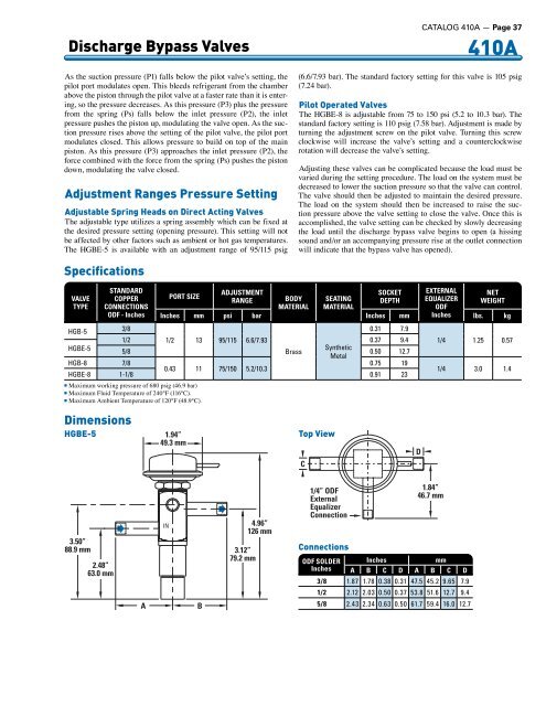
Discharge Bypass Valves<br />
As the suction pressure (P1) falls below the pilot valve’s setting, the<br />
pilot port modulates open. This bleeds refrigerant from the chamber<br />
above the piston through the pilot valve at a faster rate than it is entering,<br />
so the pressure decreases. As this pressure (P3) plus the pressure<br />
from the spring (Ps) falls below the inlet pressure (P2), the inlet<br />
pressure pushes the piston up, modulating the valve open. As the suction<br />
pressure rises above the setting of the pilot valve, the pilot port<br />
modulates closed. This allows pressure to build on top of the main<br />
piston. As this pressure (P3) approaches the inlet pressure (P2), the<br />
force combined with the force from the spring (Ps) pushes the piston<br />
down, modulating the valve closed.<br />
Adjustment Ranges Pressure Setting<br />
Adjustable Spring Heads on Direct Acting Valves<br />
The adjustable type utilizes a spring assembly which can be fixed at<br />
the desired pressure setting (opening pressure). This setting will not<br />
be affected by other factors such as ambient or hot gas temperatures.<br />
The HGBE-5 is available with an adjustment range of 95/115 psig<br />
CATALOG 410A — Page 37<br />
410A<br />
(6.6/7.93 bar). The standard factory setting for this valve is 105 psig<br />
(7.24 bar).<br />
Pilot Operated Valves<br />
The HGBE-8 is adjustable from 75 to 150 psi (5.2 to 10.3 bar). The<br />
standard factory setting is 110 psig (7.58 bar). Adjustment is made by<br />
turning the adjustment screw on the pilot valve. Turning this screw<br />
clockwise will increase the valve’s setting and a counterclockwise<br />
rotation will decrease the valve’s setting.<br />
Adjusting these valves can be complicated because the load must be<br />
varied during the setting procedure. The load on the system must be<br />
decreased to lower the suction pressure so that the valve can control.<br />
The valve should then be adjusted to maintain the desired pressure.<br />
The load on the system should then be increased to raise the suction<br />
pressure above the valve setting to close the valve. Once this is<br />
accomplished, the valve setting can be checked by slowly decreasing<br />
the load until the discharge bypass valve begins to open (a hissing<br />
sound and/or an accompanying pressure rise at the outlet connection<br />
will indicate that the bypass valve has opened).<br />
Specifications<br />
VALVE<br />
TYPE<br />
STANDARD<br />
COPPER<br />
CONNECTIONS<br />
ODF - Inches<br />
ADJUSTMENT<br />
SOCKET EXTERNAL NET<br />
PORT SIZE<br />
RANGE<br />
BODY SEATING DEPTH EQUALIZER WEIGHT<br />
MATERIAL MATERIAL<br />
ODF<br />
Inches mm psi bar Inches mm Inches lbs. kg<br />
HGB-5<br />
3/8<br />
0.31 7.9<br />
1/2 1/2 13 95/115 6.6/7.93<br />
0.37 9.4<br />
HGBE-5<br />
Synthetic<br />
5/8 Brass<br />
0.50 12.7<br />
Metal<br />
HGB-8 7/8<br />
0.75 19<br />
0.43 11 75/150 5.2/10.3<br />
HGBE-8 1-1/8 0.91 23<br />
n Maximum working pressure of 680 psig (46.9 bar)<br />
n Maximum Fluid Temperature of 240°F (116°C).<br />
n Maximum Ambient Temperature of 120°F (48.9°C).<br />
1/4 1.25 0.57<br />
1/4 3.0 1.4<br />
Dimensions<br />
HGBE-5<br />
1.94”<br />
49.3 mm<br />
Top View<br />
C<br />
D<br />
3.50”<br />
88.9 mm<br />
2.48”<br />
63.0 mm<br />
A<br />
IN<br />
B<br />
3.12”<br />
79.2 mm<br />
4.96”<br />
126 mm<br />
1/4” ODF<br />
External<br />
Equalizer<br />
Connection<br />
Connections<br />
ODF SOLDER<br />
Inches<br />
1.84”<br />
46.7 mm<br />
Inches<br />
mm<br />
A B C D A B C D<br />
3/8 1.87 1.78 0.38 0.31 47.5 45.2 9.65 7.9<br />
1/2 2.12 2.03 0.50 0.37 53.8 51.6 12.7 9.4<br />
5/8 2.43 2.34 0.63 0.50 61.7 59.4 16.0 12.7