Untitled
Untitled
Untitled

You also want an ePaper? Increase the reach of your titles
YUMPU automatically turns print PDFs into web optimized ePapers that Google loves.
Page 36 — CATALOG 410A<br />
Discharge Bypass Valves<br />
System Capacity Control<br />
On many air conditioning and refrigeration systems it is desirable to<br />
limit the minimum evaporating pressure during periods of low load<br />
either to prevent coil icing or to avoid operating the compressor at a<br />
lower suction pressure than it was designed to operate.<br />
One method that offers a practical and economical solution to the<br />
problem, is to bypass a portion of the hot discharge gas directly into<br />
the low side. This is done by a modulating control valve — commonly<br />
called a Discharge Bypass Valve (DBV). This valve, which<br />
opens on a decrease in suction pressure, can be set to automatically<br />
maintain a desired minimum evaporating pressure regardless of the<br />
decrease in evaporator load.<br />
Application<br />
Sporlan Discharge Bypass Valves provide an economical method<br />
of compressor capacity control in place of cylinder unloaders or the<br />
handling of unloading requirements below the last step of cylinder<br />
unloading.<br />
Operation<br />
410A<br />
Direct Acting Valves — HGBE-5<br />
Sporlan DBVs respond to changes in downstream or suction pressure.<br />
See Figure 7. When the evaporating pressure is above the valve setting,<br />
the valve remains closed. As the suction pressure drops below<br />
the valve setting, the valve responds and begins to open. As with all<br />
modulating type valves, the amount of opening is proportional to the<br />
change in the variable being controlled — in this case the suction<br />
pressure. As the suction pressure continues to drop, the valve continues<br />
to open until the limit of the valve stroke is reached. However,<br />
on normal applications there is not sufficient pressure change to<br />
open these valves to the limit of their stroke. The amount of pressure<br />
change from the point at which it is desired to have the valve<br />
closed, to the point at which it is to open, varies widely with the type<br />
of refrigerant used and the evaporating temperature. For this reason<br />
Sporlan DBVs are rated on the basis of allowable evaporator temperature<br />
change from closed position to rated opening. For direct acting<br />
valves, a 6°F (3.3°C) change is considered normal for most applications<br />
and is the basis of our capacity ratings. Multipliers for other<br />
temperature changes are given in the Selection Procedures section.<br />
On air conditioning systems, the minimum allowable evaporating<br />
temperature that will avoid coil icing depends on evaporator design<br />
and the amount of air passing over the coil. The refrigerant temperature<br />
may be below 32°F (0°C), but coil icing will not usually occur<br />
with high air velocities since the external surface temperature of the<br />
tube will be above 32°F (0°C). For most air conditioning systems the<br />
minimum evaporating temperature is 20°F to 25°F (-6.7°C to -3.9°C).<br />
However, when air velocities are reduced considerably, the minimum<br />
evaporating temperature should be 26°F to 28°F (-3.3°C to -2.2°C).<br />
Sporlan Discharge Bypass Valves can be set so they start to open at<br />
an evaporating pressure equivalent to 32°F (0°C) saturation temperature.<br />
Therefore, they would be at their rated capacity at 26°F (-3.3°C)<br />
evaporating temperature.<br />
The discharge bypass valve is applied in a branch line, off the discharge<br />
line, as close to the compressor as possible. The bypassed<br />
vapor can enter the low side at one of the following locations:<br />
1. Evaporator inlet with distributor<br />
2. Evaporator inlet without distributor<br />
3. Suction line<br />
Please refer to Bulletin 90-40 for a complete description of each of<br />
the above methods of application.<br />
Paralleling Valves<br />
If the hot gas bypass requirement on any system is greater than the<br />
capacity of the largest discharge bypass valve, these valves can be<br />
applied in parallel. The pressure settings of the paralleled valves<br />
should be the same to get the most sensitive performance, and the<br />
piping to each valve should be identical to keep the pressure drop<br />
across each valve the same.<br />
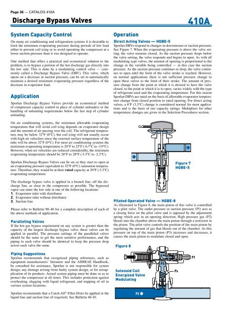
Piloted Operated Valve — HGBE-8<br />
As illustrated in Figure 8, the main piston of this valve is controlled<br />
by a pilot valve. The outlet pressure or suction pressure (P1) acts as<br />
a closing force on the pilot valve and is opposed by the adjustment<br />
spring which acts in an opening direction. High pressure gas (P2)<br />
bleeds into the chamber above the main piston through a restrictor in<br />
the piston. The pilot valve controls the position of the main piston by<br />
regulating the amount of gas that bleeds out of the chamber. As this<br />
pressure on top of the main piston (P3) increases and decreases, it<br />
causes the main piston to modulate closed and open.<br />
Fig ure 8<br />
Figure 7<br />
HGBE-5<br />
Piping Suggestions<br />
Sporlan recommends that recognized piping references, such as<br />
equipment manufacturers’ literature and the ASHRAE Handbook,<br />
be consulted for assistance. Sporlan is not responsible for system<br />
design, any damage arising from faulty system design, or for misapplication<br />
of its products. Actual system piping must be done so as to<br />
protect the compressor at all times. This includes protection against<br />
overheating, slugging with liquid refrigerant, and trapping of oil in<br />
various system locations.<br />
Solenoid Coil<br />
Energized Valve<br />
Modulating<br />
P3<br />
Ps<br />
P1<br />
Sporlan recommends that a Catch-All ® Filter-Drier be applied in the<br />
liquid line and suction line (if required). See Bulletin 40-10.<br />
P2