
You also want an ePaper? Increase the reach of your titles
YUMPU automatically turns print PDFs into web optimized ePapers that Google loves.
Contents<br />
<br />
<br />
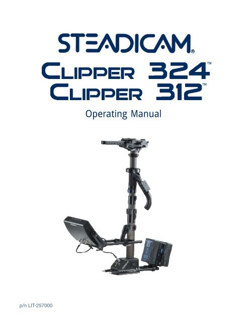
Operating <strong>Manual</strong><br />
p/n LIT-257000
<strong>Clipper</strong> <strong>324</strong>/<strong>312</strong><br />
© manual version 4/14/2008 J. Holway / L. Hayball / The <strong>Tiffen</strong> Company, LLC<br />
<strong>Clipper</strong>, <strong>Clipper</strong> <strong>324</strong>, <strong>Clipper</strong> <strong>312</strong><br />
Operating <strong>Manual</strong><br />
The <strong>Tiffen</strong> Company, LLC<br />
90 Oser Avenue<br />
Hauppauge, New York 11788<br />
631 273-2500<br />
800 645-2522<br />
631 273-2557 fax<br />
www.steadicam.<strong>com</strong><br />
2
Table of Contents<br />
Overview 4<br />
The <strong>Clipper</strong> Sled 6<br />
The Stage 8<br />
The Tilt Head 10<br />
Smart Motorized Stage 12<br />
Posts and Clamps 16<br />
Monitor Mount 17<br />
The Gimbal 18<br />
Centering the gimbal 19<br />
Base connectors 21<br />
Switch Matrix 22<br />
Frameline Generator 24<br />
Artificial Horizon 26<br />
PowerCube batteries 28<br />
Supplied Accessories 30<br />
Re<strong>com</strong>mended accessories 31<br />
Cases and Packing 31<br />
Basic Set Up<br />
Attaching the Camera 32<br />
Static Balancing 34<br />
The LX Vest 36<br />
Fitting the Vest 37<br />
The G-50 Arm 38<br />
Setting your threads 39<br />
Ride and Lift 40<br />
Goofy-foot 42<br />
Arm Posts 43<br />
Advanced Techniques<br />
Dynamic Balancing 44<br />
Inertial Control 46<br />
Low Mode 48<br />
Long Mode 52<br />
Lens Height 54<br />
Tilt Head 58<br />
Stiffening System 60<br />
Monitors 62<br />
7” Composite Monitor 63<br />
UltraBrite 2 Monitor 64<br />
Tally, FLG, Horizon Features 66<br />
Operating Tips & Warranty 67<br />
On Screen Display Functions 68<br />
Connectors, Pin-Outs & Jumpers 71<br />
Termination Jumper Settings 74<br />
Specifications & Accessories 75<br />
Appendix 76<br />
This manual is primarily written to inform experienced Steadicam operators about specific features of the<br />
<strong>Clipper</strong> <strong>324</strong> and <strong>312</strong> systems. While there is some basic information in this manual to get a novice started, we<br />
strongly urge anyone with limited Steadicam experience to take one of our three or six day workshops. For<br />
more information on professional workshops worldwide, contact The <strong>Tiffen</strong> Company at www.tiffen.<strong>com</strong>.<br />
STEADICAM, G-50, <strong>Clipper</strong>, <strong>Clipper</strong> <strong>324</strong>, <strong>Clipper</strong> <strong>312</strong>, UltraBrite, Ultra 2 are registered trademarks of the<br />
<strong>Tiffen</strong> <strong>com</strong>pany.<br />
3
The <strong>Tiffen</strong> Company takes great pride in<br />
producing the Steadicam <br />
Overview<br />
<br />
and<br />
<br />
We are <strong>com</strong>mitted to excellence,<br />
innovation and service, and<br />
the <strong>Clipper</strong> is a system that<br />
will evolve with you. Each<br />
<strong>com</strong>ponent of the <strong>Clipper</strong><br />
is carefully designed so the<br />
operator can easily configure the<br />
Steadicam to the best possible<br />
advantage for each shot.<br />
Tool free — Our guarantee that all the advanced features can be used<br />
under real-world, fast-paced conditions.<br />
Modular design — We designed the <strong>Clipper</strong>s to be easily modified,<br />
upgraded, maintained, and serviced.<br />
The optional, position-sensing, super strong, motorized stage increases<br />
the precision and repeatability of every shot. Stage positioning is<br />
smooth and effortless, and operators can trim the sled’s balance while<br />
shooting. “Go-to” buttons on the remote rebalance the sled to predetermined<br />
positions — and return “home” — with just one touch.<br />
The integral tilt head tilts +/– 15º to preserve dynamic balance, to<br />
maintain high or low lens height, to help with clearance, reach, or<br />
viewing problems, or to execute precise whip pans with the lens angled<br />
up or down.<br />
The new, Wide Dovetail Lock has a broader, more positive grip on<br />
the dovetail plate. The handle has a safety stop to prevent accidental<br />
release.<br />
The <strong>Clipper</strong>’s gimbal is the smoothest, most precise gimbal ever made,<br />
with heavy duty, high precision bearings and an ergonomic yoke, and<br />
it’s easy to take apart for cleaning. It <strong>com</strong>es with its own tool – The<br />
Blue Whale -– which operators use to precisely center the gimbal in the<br />
field, even after years of hard knocks.<br />
4
Three section, carbon fiber telescoping post extends the sled from 26 to 49 inches<br />
(66-125cm) — or anywhere in between — for short to long mode shooting. The post,<br />
monitor, and gimbal clamps are either open and free, or positively locked with the clamp<br />
levers ergonomically recessed into the clamp bodies.<br />
The swept-back monitor mount is designed for maximum stiffness, inertial control and<br />
viewing options. It has a wider range of positions, both vertically and horizontally, and the<br />
flip-to-low-mode dovetail mount is both quick and positive.<br />
Modular Electronics — A “backplane” system replaces the traditional wiring harness and<br />
supports user-replaceable circuit boards. Microprocessors are software upgradable. Quick<br />
access to the most <strong>com</strong>monly used functions — framelines, level, brightness, and contrast.<br />
Optional UltraBrite 2 monitor — 8.4 inch, 1400 nits, advanced AR coating, and HDSDI,<br />
HD <strong>com</strong>ponent, and analog <strong>com</strong>posite direct inputs. Its unique design lets it run cool<br />
without a fan. On the front is an LED artificial horizon display, and two tally lights.<br />
Structural Dovetail Base — solidly mount gyros, antlers, and other accessories. Includes<br />
positive latches for the battery rods and a pull out mounting plate for accessories.<br />
Steadicam PowerCube dual battery pack (<strong>Clipper</strong> <strong>324</strong>) provides 220 watt hours and<br />
high amperage discharge — plenty of power for the sled and today’s power hungry 35mm<br />
and High Def video cameras. The <strong>Clipper</strong> <strong>312</strong> is a 12 volt system that uses either a single<br />
PowerCube or an Anton Bauer® battery. The new tilting battery mount creates more<br />
options for balancing and inertial control.<br />
The innovative stiffening system creates extra rigidity<br />
whenever violent moves, a rough ride, or a very long post<br />
configuration requires some help.<br />
The LX vest is lightweight and ergonomic, working<br />
perfectly with the new generation of G-series arms.<br />
The G–50 arm is amazing, lifting from 12 to 50<br />
pounds (5.4 to 22.7kg). The patented “Geo” feature,<br />
which changes the spring tension as you boom up and<br />
down, makes the G-50 the smoothest arm ever, with<br />
an astounding boom range of 32 inches (81.3cm). The<br />
“Ride” adjustment precisely tunes the arm’s iso-elastic<br />
response. The arm posts are interchangeable with a<br />
rotational drag control.<br />
All the features are integral to the design; ready to be used when you need them.<br />
The <strong>Clipper</strong> <strong>324</strong> and <strong>312</strong> continue our tradition of building the world’s most versatile<br />
and user-friendly Steadicams.<br />
5
The <strong>Clipper</strong> Sled<br />
The Sled<br />
Post #2 - Uppermost and thinnest<br />
post. 1.58 inch (40.13mm) diameter.<br />
Connects the tilt head and carries the<br />
gimbal.<br />
Post #3 - middle post. Extends rig<br />
and carries the upper monitor mount.<br />
Post #4 - Carries the lower monitor<br />
mount, the base and electronics,<br />
battery rods, and lower dovetail.<br />
Stage<br />
electronics<br />
Note: If you are wondering<br />
what happened to post #1, it’s<br />
only available in the Ultra 2 .<br />
Because of the number of options<br />
over the years of several<br />
models of Ultras and <strong>Clipper</strong>s<br />
which share these posts, it’s<br />
best to keep the post names<br />
consistent...<br />
Nose box with<br />
stage electronics<br />
Docking<br />
collar<br />
Fore/aft<br />
adjustment<br />
knob<br />
Post 3 to 2 clamp<br />
Upper monitor<br />
mount<br />
Lower monitor<br />
mount<br />
Post 4 to 3<br />
clamp<br />
Monitor<br />
rods<br />
6
The only difference between the<br />
<strong>Clipper</strong> <strong>324</strong> and <strong>312</strong> sleds is the<br />
battery system. The <strong>324</strong> uses two<br />
PowerCube batteries and a down<br />
converter for 12 volts, while the<br />
<strong>312</strong> is a 12 volt system, utilizing<br />
either one or two batteries. (Note:<br />
voltage ouput levels are dependant<br />
on battery types used. Please see<br />
specifications at end of manual for<br />
details.) All other mechanical and<br />
electrical <strong>com</strong>ponents and options<br />
are identical.<br />
Nose box with<br />
stage electronics<br />
Camera mounting<br />
platform<br />
Gimbal<br />
Side to side<br />
adjustment knobs<br />
Tilt head and<br />
clamps<br />
Docking ring<br />
Gimbal<br />
clamp<br />
Transmitter<br />
for optional<br />
motorized stage<br />
(removable)<br />
Monitor<br />
bracket<br />
PowerCube<br />
Batteries<br />
Electronics<br />
module<br />
Integral<br />
dovetail base<br />
Battery rods<br />
accessory<br />
shelf<br />
7
The Stage<br />
Stage mechanics and<br />
adjustments<br />
The dovetail clamp lever has three<br />
positions: forward and locked, 90º for<br />
adjustments, and 60º<br />
back for mounting<br />
or removing the<br />
dovetail plate. A<br />
safety button must be<br />
pushed to move the<br />
lever to the unlocked<br />
position; the same<br />
button holds the<br />
lever fully open,<br />
making flips to low<br />
mode and back a bit<br />
easier. Do not force<br />
the lever backwards<br />
beyond its stop.<br />
The stage is easy to adjust. The knob at<br />
the right rear controls fore and aft, and<br />
the two knobs on the side control side to<br />
side movement.<br />
The stage connectors<br />
At the rear of the stage, left to<br />
right (port side to starboard side):<br />
•Camera power connector. 3 pin<br />
Lemo, +28V, +14V, and ground.<br />
•Video out/12V Power. 4 pin Hirose<br />
•HDSDI video in. BNC<br />
•Composite video in to video<br />
distribution base at base of sled.<br />
BNC<br />
Under the stage where the post<br />
meets the tilt head:<br />
•Two SMB connectors for two of the<br />
three RGB lines<br />
fore and aft<br />
adjustment knob<br />
side to side<br />
adjustment knob<br />
8<br />
Note: The <strong>Clipper</strong> can be<br />
ordered without a motorized<br />
stage, or with a single<br />
motor, or with two motors.<br />
Upgrading to one or two<br />
motors is a simple “plugand-play”<br />
operation.<br />
At the front (nosebox), left to<br />
right:<br />
•Power for focus motor receiver/<br />
amplifiers. 3 pin Lemo (+28V, +14V,<br />
and ground)<br />
•Tally light connector (additional<br />
functions possible)
Nosebox starboard side:<br />
•Pot to adjust Tally sensor sensitivity<br />
•Rotary switch to set remote<br />
channel (0-8)<br />
<strong>Clipper</strong> nonmotorized<br />
stage<br />
Nosebox port side:<br />
•Power and mode LEDs<br />
•Side/Side motor controls<br />
•Fore/Aft motor controls<br />
•Stage centering<br />
The <strong>Clipper</strong>’s optional motorized stage<br />
is position sensing – much like a focus<br />
motor system for a lens. One use of this<br />
feature is to set the stage to the center of<br />
travel, both fore and aft and side to side –<br />
great for initial setups.<br />
Pushing the double pole momentary<br />
switch on the “nosebox” to the “C” side<br />
centers the stage.<br />
Flipping the switch the other way (“L”)<br />
sets the stage to a pre-programmed<br />
position (more about that later.)<br />
stage motors to move. Remember this<br />
“function” when a stage motor stops<br />
working between takes!<br />
The electronics in the stage and nosebox<br />
are on “plug and play” circuit boards,<br />
easy to replace if there’s ever a problem.<br />
It’s also easy to access to the inside<br />
of the stage — to clean, add or swap<br />
motors, adjust the bearings, take apart for<br />
servicing, etc.<br />
<strong>Clipper</strong> nonmotorized<br />
stage<br />
The speed and direction of the motors<br />
is set by the switches and thumbwheel<br />
pots on the left (port) side of the nosebox<br />
(S/S & F/A). Note that the motor<br />
direction switches also have a center-off<br />
position, just in case you are in an odd<br />
RF environment or you don’t want your<br />
9
The Tilt Head<br />
Tilt Head<br />
The integral, low profile head is designed<br />
to alter the lens angle +/-15º from<br />
horizontal with only a minor shift of the<br />
camera’s c.g.<br />
The most important use of<br />
the tilt head is in normal<br />
operating. Instead of<br />
trimming even two or three<br />
degrees for a shot by<br />
altering the <strong>Clipper</strong> <strong>324</strong>’s<br />
balance, use the tilt head<br />
to preserve a perfectly<br />
vertical post and keep your<br />
sled in dynamic balance.<br />
Trim for headroom<br />
Without the tilt head, much of the benefit of getting the sled into dynamic balance is<br />
wasted when one alters the trim of the rig. For example, operators routinely trim their<br />
sleds for headroom. This action puts the rig out of both static and dynamic balance.<br />
10<br />
With the <strong>Clipper</strong> <strong>324</strong>, the operator<br />
determines the proper length of sled,<br />
optimal monitor viewing position, inertia,<br />
and lens height. Then the operator adjusts<br />
the camera to the nominal tilt angle for<br />
the shot.
Setting the tilt<br />
The operator sets the tilt by releasing the two clamps and manually repositioning the<br />
camera to the proper angle.<br />
Note: Don’t grab the<br />
stage by the nosebox<br />
to adjust tilt. Be sure to<br />
loosen the arc clamps<br />
fully and grab the camera<br />
or dovetail plate. Don’t<br />
force anything; it should<br />
move fairly easily.<br />
The post remains vertical and the rig stays in (or close to) dynamic balance. Only<br />
minor static rebalancing is normally required, but exactly how much depends on the<br />
camera, accessories, sled length, monitor position, etc. In all cases, bringing the sled<br />
back into static balance by moving the camera will return the sled to dynamic balance<br />
as well (see page 44).<br />
The Tilt Head — General<br />
Operating<br />
Even if the Steadicam is slightly out of<br />
perfect dynamic balance, it’s a whole lot<br />
easier to hold the post vertical than at<br />
any other angle, especially when panning<br />
and accelerating - which we tend to do<br />
a lot when operating a Steadicam. The<br />
tilt head keeps the post vertical in many<br />
situations, making it easier to operate and<br />
keep things level.<br />
Long mode pans with the lens looking<br />
down - say at a crowd - used to be<br />
exceedingly difficult or impossible, due<br />
to the large spatial translations of the<br />
battery, monitor, and camera. But the tilt<br />
head leaves the post vertical and therefore<br />
eliminates this spatial translation, and<br />
makes these pans routine.<br />
Low mode and very low mode pans are<br />
also much easier and more precise.<br />
Another benefit of the tilt head: a whole<br />
new class of whip pans is now possible.<br />
All whip pans are done in dynamic<br />
balance with the post vertical. Previously<br />
this meant that the lens was always<br />
horizontal. With the tilt head, the lens can<br />
be angled up or down as much as twenty<br />
degrees and the operator can still make<br />
extremely precise fast pans. Using the<br />
tilt head will increase the precision of any<br />
pan with a lens angled up or down – fast<br />
or slow.<br />
11
The motorized stage is important for precise operating<br />
Smart Motorized<br />
Stage<br />
For precise work, the Steadicam must be<br />
carefully balanced or trimmed.<br />
Before operators had a motorized stage,<br />
all balancing had to be done before<br />
the shot and therefore the Steadicam’s<br />
balance was fixed throughout the shot.<br />
As well as that works, it was, as Garret<br />
Brown has often said, a situation akin to<br />
that of an airplane pilot landing his plane<br />
to adjust the flaps.<br />
With the <strong>Clipper</strong>’s motorized stage, the<br />
operator can continuously adjust the<br />
sled’s balance during the shot — assuring<br />
the utmost precision for every moment.<br />
When you push a button to change<br />
the Steadicam’s balance, you maintain<br />
your posture, stance, and grip, so even<br />
conventional, pre-shot balancing is<br />
quicker and more accurate.<br />
This is a crew member’s view of the<br />
Steadicam operator adjusting the<br />
precise balance of the sled using the<br />
wireless transmitter — a 3 second<br />
exposure! Really!!<br />
Some situations where the<br />
motorized stage really helps:<br />
• Anytime you want to trim precisely<br />
and quickly, whether trimming on the<br />
fly, in the middle of a shot, or holding an<br />
opening frame perfectly still.<br />
• In long mode (and sometimes in<br />
standard low mode), it is often difficult or<br />
impossible for the operator to reach the<br />
stage to manually adjust the sled’s balance.<br />
12<br />
• While shooting from a vehicle, it can be<br />
awkward or even dangerous to balance the<br />
<strong>Clipper</strong> without the remote control.
“Go-to” Buttons and the<br />
Smart Motorized Stage<br />
On the remote control, there are three<br />
“go-to” buttons on one side in addition to<br />
the four original “trim” buttons (as well<br />
as two other “spare” buttons).<br />
Programming is a snap; it’s just like<br />
programming stations on a car radio.<br />
Move the stage to the desired position,<br />
either manually or using the traditional<br />
trim buttons. Then hold one of the goto<br />
buttons down for three seconds. The<br />
green LED will flash twice, and it’s set.<br />
You can even program any button on<br />
the fly, during the shot, if you have the<br />
mental reserves...<br />
Each go-to button simultaneously<br />
programs the fore and aft and the side<br />
to side position of the stage. Trimming<br />
fore and aft may slightly alter your side<br />
to side balance, or you may want to<br />
program in a severe Dutch angle. You can<br />
even program two or three buttons for the<br />
same trim if you like, so you don’t have<br />
to think about which button to push!<br />
The positions are stored in non-volatile<br />
memory, so changing batteries or turning<br />
off the sled power does not erase your<br />
presets.<br />
The go-to buttons move the stage<br />
to specific marks, defined by the<br />
operator. One position is usually the<br />
nominal balance, and the other two are<br />
programmed for some other part of the<br />
shot. During the shot, the operator (or an<br />
assistant holding the removable remote)<br />
pushes and quickly releases a go-to<br />
button to move the stage precisely to a<br />
new trim setting. Pushing the “home”<br />
button at any time returns the stage to<br />
the nominal trim. No more counting<br />
revolutions or so many seconds; the stage<br />
moves exactly where you want it to —<br />
and back.<br />
In addition to big tilts and Dutch angles,<br />
you might set a button to “post perfectly<br />
vertical and in dynamic balance,” and use<br />
another button for the nominal trim for<br />
the shot at hand. Or set the three buttons<br />
to roughly account for the side to side<br />
movement of film in some magazines.<br />
The center go-to button on remote shares<br />
the same preset as the “L” position on the<br />
switch on the nose box. The “L” position<br />
is programmed exactly like the center goto<br />
button on the remote, and the red mode<br />
LED on the nosebox will flash to confirm<br />
programming.<br />
The “C” button can be programmed the<br />
same way as the “L” button. It might be<br />
useful to reprogram the “center” position<br />
if you were working with a camera<br />
and the nominal balance was shifted<br />
significantly side to side. Then every time<br />
you changed lenses or started the day you<br />
would not have far to go to rebalance side<br />
to side.<br />
Holding one of the go-to buttons down<br />
for more than six seconds will clear all<br />
programming for that button and make<br />
it non-operational. The green LED will<br />
flash 3 times. It’s a good idea to clear out<br />
all 3 buttons at the beginning of the day.<br />
13
Ergonomics<br />
To angle the remote, loosen the small set<br />
screw in the curved handle of the gimbal.<br />
Smart Motorized<br />
Stage<br />
regular<br />
The remote control is ergonomically<br />
designed, and it rotates to any angle<br />
for your <strong>com</strong>fort, whether you operate<br />
normally or goofy-footed.<br />
Orient the remote by screwing the curved<br />
handle in or out. If the handle is too far<br />
in, you can’t easily remove the remote<br />
via the black knurled ring, and you might<br />
have to back the handle off one full turn.<br />
Loosening the setscrew a lot further and<br />
unscrewing the handle is also how you<br />
access the “tilt” bearings and shaft for<br />
cleaning.<br />
goofy<br />
Low mode: Typically, the<br />
remote is upside down<br />
in low mode. With the<br />
<strong>Clipper</strong> you can orient<br />
the remote for better low<br />
mode operation.<br />
For goofy foot operators, the remote<br />
can be inserted upside down keeping<br />
the go-to buttons on the “thumb side.”<br />
You might, however, prefer accessing<br />
the go-to buttons with your index finger:<br />
i.e., orient the remote as you wish.<br />
14
Removing the remote<br />
Whenever you want to hand the remote off<br />
to your assistant (or charge the remote’s<br />
battery), unscrew the knurled ring.<br />
Charging the remote<br />
If the transmitter’s battery is low, the<br />
LED will blink continuously after any<br />
button is depressed. To charge the remote,<br />
remove it from the gimbal handle. Plug<br />
the supplied cable into the remote and<br />
the other end into either one of the 4-pin<br />
HRS connectors on the sled.<br />
Changing the frequency<br />
To avoid interference with other systems,<br />
1 of 8 channels can be selected via the<br />
rotary switch on starboard side of nose<br />
box.<br />
The remote is held in place by two sets<br />
of pins. The forward set of pins slips into<br />
two small holes, and the rear set of pins<br />
are captured in a groove in the knurled<br />
ring.<br />
When returning the remote to the handle,<br />
insert the pins carefully and do not force<br />
anything.<br />
If you want, you can remove the pins and<br />
just Velcro ® the remote to the handle. A<br />
“half moon” filler plate is supplied with<br />
gimbal so that if the remote is removed,<br />
the filler can take its place.<br />
Leave the sled on as you charge the<br />
battery. It takes about 5 hours to charge<br />
a <strong>com</strong>pletely discharged remote battery.<br />
When the battery is charging, the green<br />
LED will be on. When the lithium-ion<br />
battery is fully charged, the green light<br />
goes off.<br />
If plugging in a fully charged transmitter,<br />
the LED will remain lit for approximately<br />
ten minutes until the charge circuit<br />
determines the battery is actually full.<br />
Battery life can vary depending on how<br />
often the transmitter is used and the<br />
storage and operating conditions.<br />
The remote and the receiver must be<br />
on the same channel. Simultaneously<br />
holding down the top 2 go-to buttons<br />
for 6 seconds will enter the remote into<br />
a channel change mode. The number of<br />
LED blinks will correspond to channel<br />
selected.<br />
Change channels by pressing the fore or<br />
aft remote buttons (channel up or down).<br />
After the proper channel is selected, the<br />
programming mode will time out after 9<br />
seconds and re-flash the selected channel<br />
number. Channel 0 corresponds to 8<br />
flashes.<br />
(For operation outside of the USA) To<br />
select between US and UK frequency<br />
operation, there are two jumpers that<br />
must be changed. One jumper is inside<br />
the nosebox, the other is inside the<br />
remote. They must match for the system<br />
to work. The jumpers are set at the<br />
factory at the time of shipping. (902<br />
– 928MHz US and 868 to 870MHz UK)<br />
The green “PWR” LED on nose box<br />
<strong>com</strong>es on when the CPU is operational.<br />
15
Posts & Clamps<br />
Posts and clamps<br />
The three sections of the telescoping post<br />
are adjusted by releasing the clamps at<br />
the top of each section. Be sure to support<br />
all sled portions that will be freed before<br />
you release the clamp.<br />
Locking the post clamps<br />
The <strong>Clipper</strong>’s post clamps are positive<br />
locking. They are either fully open or<br />
closed, and they<br />
snap shut with a<br />
healthy, positive<br />
click.<br />
Do not force<br />
the lever<br />
further open<br />
than shown,<br />
as this can<br />
damage the<br />
mechanism<br />
Note: There is no safety line<br />
inside the posts to keep them<br />
from separating, but there are<br />
electrical wires inside the post<br />
that will keep the rig parts<br />
together. The longer the rig,<br />
the more these wires will act<br />
like a safety line, but don’t rely<br />
on them.<br />
Do not extend any section beyond the<br />
point where the yellow alignment line<br />
be<strong>com</strong>es red.<br />
Do not twist the bottom section more<br />
than 180 degrees from the top section as<br />
this will also twist the internal cables. If<br />
you think you may have inadvertently<br />
twisted the internal cables, remove the<br />
camera and battery and make the rig as<br />
short as possible. Release the clamp and<br />
slide the bottom section (the electronics)<br />
<strong>com</strong>pletely off. Examine the curly cord.<br />
The two rubber tubes that support the<br />
wires should be parallel and not twist.<br />
Rotate the bottom section until the rubber<br />
tubing is not twisted, and put the sled<br />
back together.<br />
It’s always good practice to give the rig a<br />
whip pan and hard stop to be sure nothing<br />
shifts.<br />
If something shifts, the clamps are easily<br />
tightened with a small Allen wrench<br />
(3/32”). Adjust the screws with the<br />
lever closed — and go slowly — 1/8th<br />
of a turn or less at a time. Tighten both<br />
screws equally, so the clamp remains<br />
parallel to the housing. If the screws are<br />
over-tightened, the lever may not open<br />
or close. Test the clamp strength and<br />
lever action frequently as you adjust the<br />
tension.<br />
16
Monitor mounts<br />
There are two monitor mounts on the <strong>Clipper</strong>, one on post four (the<br />
bottom post) and one on post three. The two mounts are identical, and<br />
permit a large vertical range of monitor positions. The second monitor<br />
mount can be used for securely mounting a gyro, recorder, second<br />
monitor, etc.<br />
Inserting the monitor mount<br />
Align the parts parallel and squarely to each other. Note that the bracket<br />
is inserted half-way to start, rather than from above and trying to slide<br />
down the whole way from the top. The safety pin automatically retracts<br />
as you align the parts, and clicks to lock when the parts are aligned.<br />
Tighten the Kipp ® handle hard to secure the monitor bracket.<br />
Accessory shelf<br />
Tucked inside the base of the sled is<br />
an accessory shelf for mounting extra<br />
monitors and recording devices.<br />
The shelf is adjusted by removing<br />
four screws.<br />
Maintenance<br />
The <strong>Clipper</strong> uses several different tool free clamps. Although they all <strong>com</strong>e preadjusted<br />
at the factory, they will have to be adjusted from time to time. The key thing<br />
is to tighten the clamps a little at a time; a small change in a clamp’s adjustment can<br />
produce enormous changes in the pressure on the parts. In general, the clamps should<br />
be just tight enough to work.<br />
Use a 3/8ths inch open end<br />
wrench to tighten or loosen the<br />
lock nut for the monitor rods<br />
clamp.<br />
Tighten or loosen in 1/8th of<br />
a turn or smaller increments,<br />
testing often both for the<br />
clamp’s holding strength and<br />
for the action of the lever.<br />
17
The gimbal<br />
The Gimbal<br />
The <strong>Clipper</strong> shares the same gimbal as<br />
its bigger cousin, the Ultra 2 . The gimbal<br />
has been <strong>com</strong>pletely redesigned with<br />
higher-precision, high load bearings. The<br />
gimbal body, yoke, and handle are strong<br />
and precisely registered to each other.<br />
The yoke’s new shape and contoured<br />
edges extends the range of motion<br />
without interference and promotes a<br />
better operating grip over a wider range<br />
of positions.<br />
Note: You might notice that<br />
there is a small amount of<br />
in and out “play” between<br />
the handle that holds the<br />
remote and the Y shaped<br />
yoke. This is part of the<br />
gimbal design and is<br />
normal. In use, the play<br />
disappears.<br />
18
Centering the gimbal<br />
Note: This procedure is not necessary with a new rig from the<br />
factory.<br />
The operator can easily center the gimbal in the field – useful if<br />
you’ve taken apart the gimbal for cleaning, taken a really bad<br />
bump, etc.<br />
• Rotate the sled 90 ° so that the camera<br />
is aimed at along the axis of the yoke<br />
handle, as shown in the photo below.<br />
Tweak the fore-aft balance as precisely<br />
as you can, then do not touch the stage<br />
adjustments for the rest of the procedure.<br />
• Place the gimbal on the docking stud (as<br />
you would for normal balancing), give<br />
yourself a four second drop time, and<br />
aim the camera along a line through the<br />
two bearings in the yoke, as shown in the<br />
photo above.<br />
• Balance side to side and fore-aft as<br />
precisely as you can to get the post<br />
vertical. We re<strong>com</strong>mend you use a bubble<br />
level on the stage, and be sure that the tilt<br />
head is set 90 ° to the post (horizontal).<br />
• Rotate the sled 90° again, as shown<br />
below, and test for level. Rotate 180°and<br />
test for level.<br />
Tip: We urge you to test your gimbal’s centering with a<br />
normal drop time, and then with progressively longer<br />
drop times. Go slowly and follow the procedure closely,<br />
rebalancing carefully and testing everything as you go.<br />
Before you adjust anything, be sure it’s not your balancing<br />
technique that is causing the problem, or a dangling cable,<br />
anything loose on the sled, or the wind. With long drop times,<br />
the sled is very sensitive to these shifts and influences.<br />
• If the sled is level, great. STOP and DO<br />
NOT ADJUST ANYTHING.<br />
19
Gimbal Centering<br />
• Continue only if the sled is not level in both<br />
directions. Use the optional blue whale tool to<br />
loosen one of the two end caps 1/16 of a turn<br />
or so, and tighten the other one to the same<br />
degree.<br />
Blue Whale Tool<br />
• Turning the end caps moves the inner gimbal ring relative to the yoke, centering the<br />
gimbal.<br />
• If the sled does not hang perfectly level, move the whole sled “uphill” with the two<br />
end caps.<br />
• If it gets worse, you chose the wrong one to loosen! If it gets better, keep going until<br />
it is perfect. Do not rebalance fore and aft with the stage.<br />
Adust the end caps equally – i.e. loosen one and tighten the other the same amount —<br />
and do it in small increments.<br />
A small warning: do not over-tighten the caps against the<br />
bearings, as this will cause binding. Just tighten each cap<br />
down to touch the bearing. If the bearing starts to bind,<br />
just back off one of the two end caps until the gimbal is<br />
free again. The blue whale tool also makes it easy to take<br />
apart and clean the gimbal if this ever be<strong>com</strong>es necessary.<br />
20
The base connectors<br />
•Top: Monitor connector: 12 and 24<br />
volt power, <strong>com</strong>posite video, and<br />
data transmit and receive lines. 8<br />
pin Lemo.<br />
Base Connectors<br />
•Left: RCA video in/out for a video<br />
recorder. A small slide switch on<br />
the back sets in or out (see below).<br />
•Center: HDSDI, direct connection<br />
to HDSDI connector in stage; no<br />
connection to the video distribution<br />
amplifier. If your electronics fail,<br />
you can use this connector to send<br />
a <strong>com</strong>posite video signal to the<br />
monitor. BNC.<br />
•Right: Video out and +14 VDC. 4<br />
pin HRS.<br />
•Bottom: Auxiliary 28 and 14 volt, 3<br />
pin Lemo, good for powering gyros<br />
or other accessories.<br />
•Lower front (between the rods): two<br />
SMB connectors for the red and<br />
blue lines for HD <strong>com</strong>ponent video.<br />
Direct connection to the two SMB<br />
connectors under the stage.<br />
Note: If you are not using the HDSDI<br />
and/or the HD <strong>com</strong>ponent lines, you<br />
may use them for other purposes, such<br />
as a microphone line down the post or<br />
speaker wires up the post.<br />
21
<strong>Clipper</strong> <strong>324</strong>/<strong>312</strong> Switch Matrix<br />
Switch Matrix<br />
On top of the <strong>Clipper</strong>’s base is a multiposition<br />
switch that determines what<br />
standard definition video signal appears<br />
on the monitor and at the three video<br />
output connectors. It has no effect on<br />
High-definition signals.<br />
There are two possible sources for the<br />
video signal: the camera (via the BNC on<br />
the stage), and a signal fed into the RCA<br />
jack on the front panel of the sled base.<br />
The latter is only available if the “In-Out”<br />
switch is set to “In.”<br />
There are four video outputs: the monitor,<br />
the two Hirose connectors, and the RCA<br />
jack when set to “Out.”<br />
You can add framelines to the camera’s<br />
video signal to each output.<br />
It is not possible to add framelines to a<br />
video signal <strong>com</strong>ing into the RCA jack.<br />
The RCA jack, when set to “In,” sends<br />
video only to the monitor. The two Hirose<br />
connectors always are fed a signal from<br />
the camera.<br />
The default setting (#8) adds framelines<br />
to camera’s video signal going to the<br />
monitor, but not to the RCA connector,<br />
nor to the two Hirose connectors.<br />
Settings 0 though 7: Framelines are not<br />
added to the camera’s video signal that<br />
is sent to the monitor. You have various<br />
choices and <strong>com</strong>binations of adding<br />
framelines or not to the other outputs.<br />
Settings 8 though F: Framelines are<br />
added to the camera’s video signal that<br />
is sent to the monitor. You have various<br />
choices and <strong>com</strong>binations of adding<br />
framelines or not to the other outputs.<br />
Example: You want framelines added to<br />
the monitor and to the RCA output (i.e.,<br />
to a recorder), but not to either Hirose<br />
connector. Use setting #9.<br />
Connector<br />
0 1 2<br />
* Mon (Front Panel)<br />
Camera Video Input X X X<br />
Camera Video Input with FLG Overlay<br />
RCA Video Input<br />
† Mon (Front Panel)<br />
Camera Video Input<br />
Camera Video Input with FLG Overlay<br />
RCA Video Input X X X<br />
* RCA (Front Panel)<br />
Camera Video Input X X<br />
Camera Video Input with FLG Overlay<br />
X<br />
Hirose (Front panel)<br />
Camera Video Input X X X<br />
Camera Video Input with FLG Overlay<br />
Hirose (Stage)<br />
Camera Video Input X X<br />
Camera Video Input with FLG Overlay<br />
NOTE:<br />
* = RCA switch set to "OUT" position.<br />
† = RCA switch set to "IN" position.<br />
Position #8 is the default position.<br />
The 12 and 24 volt low battery warning<br />
levels are set at the factory. If you want<br />
to alter the settings, there are two pots,<br />
marked 12T and 24T for this purpose.<br />
To adjust each pot: Set the sled for 12<br />
or for 24 volt operation. Hook the sled<br />
up to a variable power supply, dial in<br />
the voltage that you want as the warning<br />
point, and adjust the pot until “low<br />
battery” is indicated: LED’s flash next<br />
to the on-off switch and the on-screen<br />
indicator blinks.<br />
An alternative method: power the sled<br />
from a battery. Wait until the low voltage<br />
indicator on the battery starts to show<br />
low, then adjust the pot until the sled<br />
shows a low voltage. Or you can calibrate<br />
using the battery voltage indicator on<br />
some cameras.<br />
X<br />
22
Selector Switch Position <strong>Clipper</strong> <strong>312</strong>/<strong>324</strong> (257-0003 PCB) 02-25-08<br />
0 1 2 3 4 5 6 7 8 9 A B C D E F<br />
el)<br />
put X X X X X X X X<br />
rlay X X X X X X X X<br />
put<br />
el)<br />
put<br />
rlay<br />
put X X X X X X X X X X X X X X X X<br />
el)<br />
put X X X X X X X X<br />
rlay X X X X X X X X<br />
el)<br />
put X X X X X X X X<br />
rlay X X X X X X X X<br />
e)<br />
put X X X X X X X X<br />
rlay X X X X X X X X<br />
sition.<br />
ition.<br />
position.<br />
23
How to set up your frameline generator<br />
Frameline Generator<br />
The four buttons on the frameline generator control<br />
the framelines, crosshairs, on-screen horizon position,<br />
and battery indicator position, as well as the frameline<br />
style, crosshair style, graphic brightness, graphic<br />
elements on or off, and two stored frameline and<br />
graphic presets.<br />
Frameline Mode<br />
Descriptions<br />
MODE ENTRY REQUIREMENTS<br />
KEY FUNCTIONS WHILE IN MODE<br />
# MODE UP DOWN LEFT RIGHT UP DOWN LEFT RIGHT<br />
1<br />
2<br />
3<br />
4<br />
Recall Frameline<br />
Position #1<br />
Store Frameline<br />
Position #1<br />
Recall Frameline<br />
Position #2<br />
Store Frameline<br />
Position #2<br />
>2 sec.<br />
>4 sec.<br />
>2 sec.<br />
>4 sec.<br />
5 FLG On/Off >1 sec.<br />
6 Graphics On/Off >1 sec.<br />
7 Cross Hair position >1 sec. >1 sec. Move UP Move DOWN Move LEFT Move RIGHT<br />
8 Horizon position >2 sec. >2 sec. Move UP Move DOWN Move LEFT Move RIGHT<br />
9 Battery position >3 sec. >3 sec. Move UP Move DOWN Move LEFT Move RIGHT<br />
10 Graphics Brightness >1 sec. >1 sec. DECREASE all INCREASE all<br />
12<br />
13<br />
Lower & Left<br />
Frameline position >1 sec. >1 sec. Move UP Move DOWN Move LEFT Move RIGHT<br />
Upper & Right<br />
Frameline position >1 sec. >1 sec. Move UP Move DOWN Move LEFT Move RIGHT<br />
14 Frameline style select >1 sec. >1 sec. Style #1 Style #2 Style #3 Style #4<br />
15 Cross Hair style select >2 sec. >2 sec. Style #1 Style #2 Style #3 Style #4<br />
16 EXIT X X<br />
17 Factory Reset X X<br />
24
The charts tell you how it all works —<br />
here’s one example. Suppose you want<br />
to move the position of the horizon<br />
display. You enter the horizon position<br />
mode by simultaneously pushing down<br />
the left and right buttons for about two<br />
seconds. The horizon graphic will pulse<br />
on and off. You move the graphic UP,<br />
DOWN, LEFT, or RIGHT by pushing the<br />
appropriate button.<br />
If no buttons are pressed for several<br />
seconds, the FLG will exit the horizon<br />
position mode. You could also press the<br />
up and down buttons simultaneously to<br />
exit the programming mode.<br />
You can store the current settings for the<br />
framelines, crosshair, horizon, and battery<br />
by holding down the UP button for about<br />
four seconds. “SET #1” will be displayed<br />
on the screen for one second.<br />
If you change something and want to<br />
return to these settings, just push the UP<br />
button for about 2 seconds — “PRESET<br />
#1” will be displayed on screen for one<br />
second. Note the little “1” symbol by the<br />
upper button.<br />
The second preset is controlled by the<br />
RIGHT button — it’s also marked “2.”<br />
Frameline Mode<br />
Descriptions<br />
# MODE<br />
1<br />
2<br />
3<br />
4<br />
Recall Frameline<br />
Position #1<br />
Store Frameline<br />
Position #1<br />
Recall Frameline<br />
Position #2<br />
Store Frameline<br />
Position #2<br />
5 FLG On/Off<br />
6 Graphics On/Off<br />
IN-MODE INDICATION<br />
DISPLAYED ON SCREEN MODE EXIT REQUIREMENTS COMMENTS<br />
"*" displayed in top center<br />
of screen while in any mode<br />
"RCL 1" confirmation<br />
displayed on screen for 1 sec.<br />
"SET #1" confirmation<br />
displayed on screen for 1 sec.<br />
"RCL 2" confirmation<br />
displayed on screen for 1 sec.<br />
"SET #2" confirmation<br />
displayed on screen for 1 sec.<br />
n/a<br />
n/a<br />
n/a<br />
n/a<br />
All position #1 settings recalled and displayed<br />
for Frameline, Cross Hair, Horizon, and Battery<br />
All position #1 settings stored<br />
for Frameline, Cross Hair, Horizon, and Battery<br />
All position #2 settings recalled and displayed<br />
for Frameline, Cross Hair, Horizon, and Battery<br />
All position #2 settings stored<br />
for Frameline, Cross Hair, Horizon, and Battery<br />
Frameline display is toggled<br />
on and off n/a Frameline OSD is toggled on and off.<br />
Horizon, Cross Hair, and Battery<br />
OSD's are toggled on and off.<br />
n/a<br />
Horizon, Cross Hair, and Battery OSD's are toggled<br />
on and off.<br />
7 Cross Hair position Cross Hair graphic pulses on and off<br />
Timed-out if no buttons pressed<br />
or activate EXIT mode<br />
Cross Hair graphic can be moved anywhere on screen.<br />
8 Horizon position Horizon graphic pulses on and off<br />
Timed-out if no buttons pressed<br />
or activate EXIT mode<br />
Horizon graphic can be moved anywhere on screen.<br />
9 Battery position Battery graphic pulses on and off<br />
Timed-out if no buttons pressed<br />
or activate EXIT mode<br />
Battery graphic can be moved anywhere on screen.<br />
10 Graphics Brightness<br />
Entire frameline graphics pulses<br />
on and off<br />
Timed-out if no buttons pressed<br />
or activate EXIT mode<br />
Brightness adjustment of OSD graphics.<br />
12<br />
Lower & Left<br />
Frameline position<br />
Lower and Left frameline graphic line<br />
pulses on and off<br />
Timed-out if no buttons pressed<br />
or activate EXIT mode<br />
Framelines can be moved anywhere on screen.<br />
13<br />
Upper & Right<br />
Frameline position<br />
Upper and Right frameline graphic line<br />
pulses on and off<br />
Timed-out if no buttons pressed<br />
or activate EXIT mode<br />
Framelines can be moved anywhere on screen.<br />
14 Frameline style select<br />
A selection of frameline styles<br />
will be shown on the screen.<br />
Frameline style changes to selected<br />
pattern after button press.<br />
Selection between 1 of 4 pre-determined<br />
Frameline line graphics.<br />
15 Cross Hair style select<br />
A selection of cross hair styles<br />
will be shown on the screen.<br />
Cross Hair style changes to selected<br />
pattern after button press.<br />
Selection between 1 of 4 pre-determined<br />
Cross Hair graphics.<br />
16 EXIT n/a n/a Exit all modes and returns to main display.<br />
With both buttons pressed at power up,<br />
17 Factory Reset n/a n/a<br />
system is reset to factory default settings.<br />
Note: Pure white graphics won’t dim (mode<br />
10). Choose a gray graphic or frameline if you<br />
want to dim it.<br />
25
Artificial Horizon<br />
The Artificial Horizon<br />
Adjustments, and displays<br />
The <strong>Clipper</strong> artificial horizon has three<br />
controls – a button and two rotary<br />
switches. The button on the back of the<br />
electronics base controls the zero offset,<br />
direction, type of display, and horizon on/<br />
off. The switches are accessible via holes<br />
on the port side of the base. One switch<br />
controls the “range” of the display and<br />
the other the “rate.”<br />
The button on the back<br />
LED’s on display will flash to confirm<br />
that a mode change has occurred. Be sure<br />
to re-set the zero offset when going to<br />
low mode and back.<br />
Pressing the button for three to five<br />
seconds will switch the LED display<br />
from bar graph mode to “night rider” dot<br />
mode. Again, the center two LED’s on<br />
the display will flash to indicate that a<br />
mode change has occurred.<br />
Pressing the button for five to thirty<br />
seconds turns horizon system off or on.<br />
All LED’s will be off.<br />
Pressing the button for more than 30<br />
seconds resets everything to default<br />
values.<br />
On-screen level display — only<br />
available with <strong>com</strong>posite video<br />
signals.<br />
26<br />
Pushing the button for less than 1 second<br />
will reset the sled level (sets the “zero<br />
offset”).<br />
Place a small<br />
bubble level on a<br />
surface parallel to<br />
the bottom frame<br />
of your camera<br />
(usually the dovetail<br />
plate works well).<br />
Angle and hold<br />
the sled until this<br />
bubble reads level,<br />
then push and release the horizon button<br />
quickly. The display should now read<br />
“level.”<br />
Pressing the button for more than one<br />
second but less than three will flip the<br />
display direction – useful for going to<br />
low mode and back. The center two<br />
Level, UltraBrite 2 Monitor<br />
Off-level, “Night-Rider” mode<br />
Off-level, “Normal” mode
The range switch interacts with the rate<br />
switch. Typically, the smaller the range,<br />
the less integration you will need. Ranges<br />
or rates significantly larger than the<br />
default values are not typically used.<br />
Rate Choices<br />
Low Pass filter settings (6-Pole<br />
IIR filter)<br />
Choosing a Range<br />
The range switch sets the sensitivity of<br />
the display. The smaller the range, the<br />
more sensitive the display will be. The<br />
default setting is “0” or +/– 5 degrees.<br />
We suggest you experiment with settings<br />
1 through 6. The range choices beyond 5<br />
degrees might be useful if one wanted to<br />
hold a specific Dutch angle. Setting “F<br />
(15)” is the full range of the sensor.<br />
Range Choices<br />
Setting +/- Degrees<br />
0 (default) 5<br />
1 2<br />
2 2.5<br />
3 3<br />
4 3.5<br />
5 4<br />
6 4.5<br />
7 5<br />
8 5.5<br />
9 6<br />
A (10) 6.5<br />
B (11) 7<br />
C (12) 8<br />
D (13) 9<br />
E (14) 10<br />
F (15) 180<br />
Setting a Rate<br />
The rate switch sets the integration<br />
(or averaging) time. The longer the<br />
integration time (the lower the frequency<br />
or Hz), the slower the system responds.<br />
A longer integration time avoids the<br />
big, erroneous signals as you accelerate<br />
or decelerate. The faster the integration<br />
time, the more the indicator will jump<br />
around. Experiment and pick the “rate”<br />
you like.<br />
There are sixteen positions, from zero to nine, and A<br />
through F. The default setting is “0” which equals 5Hz,<br />
a good <strong>com</strong>promise. Position one (.75Hz) has the most<br />
integration and slowest response. Position F has the least<br />
integration and fastest response.<br />
Setting<br />
Hz<br />
0 (default) 5<br />
1 0.75<br />
2 1<br />
3 2<br />
4 3<br />
5 4<br />
6 5<br />
7 6<br />
8 7<br />
9 8<br />
A (10) 10<br />
B (11) 12<br />
C (12) 13<br />
D (13) 16<br />
E (14) 18<br />
F (15) 40<br />
27
PowerCube batteries<br />
Batteries<br />
The PowerCube batteries are 6.0 Ah,<br />
14.8V. Please read the literature that<br />
<strong>com</strong>es with each battery and charger for<br />
details.<br />
The <strong>Clipper</strong> <strong>312</strong>, 12V parallel<br />
<strong>Clipper</strong> <strong>324</strong> normal, 24 volt,<br />
(two batteries in series)<br />
Generally we use the battery in pairs,<br />
generating (nominally) 29.6VDC. It’s<br />
best to use batteries that are roughly<br />
equally charged. Both batteries power<br />
the 14.4 volt DC to DC converter nestled<br />
between the batteries.<br />
On the <strong>Clipper</strong> <strong>324</strong>, the on-off switch has<br />
two positions, 12 and 24 volts. In the 12 V<br />
position, only the rear battery is connected<br />
and the DC-DC converter is disconnected.<br />
The LEDs on the battery mount will<br />
blink when the low battery threshold is<br />
reached. The circuit breakers in battery<br />
mount are the standard automotive type.<br />
Discharge rate<br />
As your Lithium-Ion PowerCube<br />
batteries are used, the voltage drops<br />
at a fairly regular rate. However, the<br />
sample 30 watt discharge chart shows<br />
some interesting information. Hot off<br />
the charger, a single battery will read<br />
16.8 volts, but within a minute drops<br />
to 16.1 volts when under load. This is<br />
normal, and not a cause for concern or an<br />
indication of a weak battery.<br />
At the 30 watt discharge rate, the battery<br />
voltage drops slowly for about 3 hours<br />
from 16.1 volts to the “knee” voltage of<br />
13.8 volts – slightly faster at the upper<br />
end, and more slowly as the battery is<br />
discharged. When the voltage reaches<br />
13.8 volts, the voltage drops off very<br />
quickly to 11 volts (within 8 minutes).<br />
The batteries have a self-limiting cut-off<br />
of 11 volts.<br />
Based on this discharge curve, we<br />
suggest you set the <strong>Clipper</strong>’s battery<br />
warning at 13.8 volts if your total load is<br />
about 30 watts and 8 minutes is enough<br />
warning time.<br />
<strong>Clipper</strong> <strong>324</strong>, 12 volt only,<br />
(one battery)<br />
For a lightweight, 12 volt running rig, you<br />
might want to remove the forward battery,<br />
and/or use one Endura 7 battery. (Use<br />
two 7’s for a lightweight 24 volt rig).<br />
If you are working with 24 volt film<br />
cameras, where the load changes when<br />
the camera runs, you might set the<br />
battery warning higher, to 28.2 or more<br />
volts for the two batteries in series,<br />
again depending on the load, how much<br />
warning you need, etc.<br />
28
If the voltage drops below 26 volts when<br />
the camera is not running, you will not<br />
get any appreciable run time with most<br />
35mm, 24 volt film cameras. See page 22<br />
to see how to set the battery warning.<br />
17<br />
Discharge Characteristics of PowerCube<br />
When running electrically noisy, or high<br />
current draw cameras or accessories, low<br />
voltage indicators may briefly appear.<br />
Voltage sag due to the large loads or<br />
excessive noise spikes on the power lines<br />
may surpass the threshold settings.<br />
Rotating mount<br />
The battery mount pivots approximately<br />
180º to facilitate static and dynamic<br />
balancing, and for inertial control.<br />
Pivoting the battery all the way down<br />
will enable it to get closer to the sled,<br />
reducing pan inertia and/or helping to<br />
balance very heavy cameras. Pan inertia<br />
is maximized with the batteries horizontal<br />
and the battery rods fully extended.<br />
16<br />
15<br />
Voltage [V]<br />
14<br />
13<br />
12<br />
11<br />
Discharge Condition: 30W, 11V (EDV)<br />
Ambient Temp.: Room Temp.<br />
Discharge Time: 184.6min (92.3Wh)<br />
10<br />
0 20 40 60 80 100 120 140 160 180 200<br />
Elapsed Time [min]<br />
Charging your batteries<br />
There is no memory effect with Lithium-Ion batteries. There is also no need to<br />
deep discharge your batteries to improve their response. Charging a <strong>com</strong>pletely<br />
discharged battery (11 volts) to fully charged (at 16.8 volts) with a 3.0 amp<br />
charge takes about 2 hours and 40 minutes, but the battery reaches 80% of a full<br />
charge (at about 16.5 volts) in just over 90 minutes. The last 20% of the charge<br />
cycle takes over an hour.<br />
We suggest that if you have the time, fully charge your batteries. If you are in a<br />
hurry, however, charge them only for an hour and a half or less, as an 80% charge<br />
of these batteries is still a lot of watt-hours, and typically you are using two of<br />
them. Also don’t discharge them much below 13.8 volts if possible.<br />
If you have two of the VL-4S chargers, split the batteries equally between the<br />
chargers. Although all IDX VL-4S batteries are charged simultaneously, with<br />
one, two, or three batteries on the charger, the charge current is 3.0 amps per<br />
battery. When the fourth battery is added to the charger, the charge current for<br />
each battery drops to 2.3 amps, which will increase the time it takes to charge<br />
each battery.<br />
29
Accessories<br />
Supplied Accessories**<br />
part number<br />
Camera mounting dovetail 802-7417<br />
Blue Whale gimbal tool 800-7114<br />
Gimbal transmitter 800-7150<br />
Gimbal battery recharging cable 800-0101<br />
Hard Case for sled 011-0355<br />
8.4” UltraBrite HD monitor 800-7500-01<br />
Power/Video cable for<br />
HD monitor 800-0102<br />
Monitor Hood 252-7565<br />
LX vest 800-7800-02<br />
Soft vest bag 078-5237<br />
Hard case (vest and arm) 011-0330<br />
G-50 arm 800-7800-02<br />
Soft arm bag 078-5236<br />
G-50 anti-backlash tool 802-7265<br />
T-handle 1/4” Allen wrench MSC-093260<br />
G-50 operating manual LIT-800720<br />
Docking bracket 250-7910<br />
PowerCube 2+2 Starter Kit FFR-000040<br />
IDX VL-4S battery charger FFR-000008<br />
Battery hard case 011-0368<br />
Stabilizing system:<br />
Vectran line<br />
MSC-200100<br />
3 ft video cable BNC CBL-017715<br />
12v accessory cable 250-0045<br />
12v Power cable, camera, HD 078-7351-01<br />
24v Power cable: Moviecam 078-7351-03<br />
Pot adjust tool<br />
MSC-104213<br />
Allen wrench pocket tool MSC-150890<br />
Screwdriver<br />
MSC-191115<br />
Steadicam logo cap<br />
FFR-000021<br />
Spare ratchets with hardware<br />
Camera mounting screws,<br />
1/4-20 078-1121<br />
3/8 - 16 078-1122<br />
EFP Instructional Video DVD-200504<br />
Cap, Vinyl, 1/8 – 3/16 OD MSC-300580<br />
Cap, Vinyl, 3/8 – 7/16 OD MSC-300581<br />
Nut, 8-32 Hex, Thin<br />
NUT-832010<br />
8-32 x 1/2 Bind HD Slot SCW-832006-1<br />
Washer #8 Flat, SS<br />
WHR-803<br />
Washer #8 Split Lock<br />
WHR-806<br />
Warranty Form<br />
LIT-077200<br />
1” Buckle & Receptor MSC-079901<br />
T-Handle, 5/32 x 8.5 Hex MSC-093270<br />
30<br />
**Available options and accessories vary by model.
Re<strong>com</strong>mended Cables and Accessories<br />
Additional PowerCube Batteries<br />
FFR-000035<br />
Spare power/video cable for HD monitor 800-0102<br />
Spare gimbal battery recharging cable 800-0101<br />
Spare 3 ft video cable 078-4122-01<br />
2 spare 12 ft video cables<br />
Spare 12v accessory cable 250-0045<br />
2 each of all camera power cables you will use various<br />
RED power cable to 3-pin LEMO 802-0106<br />
2 HD <strong>com</strong>ponent cables, camera to sled<br />
2 HD <strong>com</strong>ponent cables, sled to monitor<br />
Slanted F-bracket and safety pin 252-7906<br />
Low mode handle clamp 078-7393-02<br />
6 inch G-50 arm post 257-7202-2<br />
Camera mounting dovetail 802-7417<br />
Battery rod weights 800-7617<br />
Follow focus rod mounting hardware and rods 250-7915<br />
Also:<br />
Wireless follow focus system<br />
and brackets<br />
Video transmitting and<br />
receiving system<br />
Wired zoom control system<br />
Camera specific low mode brackets<br />
Inertial augmentation<br />
(Antlers or Gyros)<br />
Video recording system<br />
IDX VL-4S battery charger<br />
FFR-000008<br />
Tape measure<br />
Many spare camera screws:<br />
1/4-20 and 3/-16 078-1121/078-1122<br />
monitor fuse<br />
Mitchell mount adaptor 800-7902<br />
Cases & packing<br />
When repacking the sled into the case, Insert the monitor first,<br />
with the rods angled up. Be sure that the sled length and gimbal<br />
position are properly set so that the sled drops freely into place,<br />
then rotate the monitor rods down into their final position.<br />
Many operators cut the foam to ac<strong>com</strong>modate accessories kept<br />
on the sled - such as a focus motor receiver or a small VCR. A<br />
long, thin razor blade works fairly well to cut the foam, as does<br />
a serrated knife.<br />
The hard sled and vest cases have wheels and a retractable<br />
handle.<br />
Soft bags are provided for the arm and for the vest, but you<br />
should also use the hard case when shipping your gear.<br />
Many other accessories are shipped in the battery case. Most<br />
operators have several other cases for their accessories, tools,<br />
low mode brackets, video recorders, video transmitters,<br />
diversity receivers, remote focus equipment, etc.<br />
31
Attaching the Camera<br />
Attaching the<br />
Camera<br />
Camera c.g. .75” (19mm)<br />
behind center post – fore-aft.<br />
Camera c.g. centered<br />
over post – side to side.<br />
The basic idea: We want to position the camera’s center of gravity about .75 inch<br />
behind the centerline of the post fore-aft (as seen from the side) and directly over<br />
the centerline of the post side to side (as seen from the front or rear). We do this to<br />
facilitate both static and dynamic balancing. We fine-tune the placement of the camera<br />
as we balance the rig. See page 34.<br />
First, center the side to side and fore-aft adjustments of the camera mounting platform,<br />
using the knobs, the remote control, or better yet, flip the centering switch to “C” and<br />
the motorized stage centers itself!<br />
Attach all the accessories to the camera, including lenses, loaded film magazines,<br />
focus motors, obie lights, transmitters, etc. Don’t worry too much if you must add your<br />
motors or other accessories after you have attached the dovetail plate.<br />
Using a rod or pencil, find the c.g. of the camera, both fore-aft and side to side.<br />
Temporarily mark this with pieces of tape.<br />
Finding the camera’s fore-aft<br />
center of gravity.<br />
Finding the camera’s side to<br />
side center of gravity.<br />
32
Attach the long dovetail plate to the<br />
bottom of the camera, centered as closely<br />
as possible under the camera’s c.g.<br />
Use two screws to keep the plate from<br />
rotating.<br />
Dovetail locking lever fully open.<br />
Closing the locking lever.<br />
If possible, attach a second dovetail plate<br />
to the top of the camera, directly above<br />
the other dovetail. This may require<br />
additional hardware, such as a special<br />
low mode bracket for your camera.<br />
If the camera won’t drop fully into place,<br />
be sure the left side of the dovetail is<br />
fully inserted, all is parallel, and the<br />
locking lever is fully open. It’s a close fit.<br />
Push firmly.<br />
The dovetail locking lever has<br />
three positions (see page 8):<br />
After the dovetail drops into place, close<br />
the locking lever half way and slide<br />
the camera until the fore-aft c.g. mark<br />
is about .75 inches (19mm) behind the<br />
centerline of the telescoping posts. Post<br />
#2 is 1.580 (40.13mm) in diameter, so<br />
you can use the back of the post as a<br />
guide for placing the camera c.g.<br />
Push the locking lever forward to fully<br />
lock the camera into place. You are now<br />
ready to static balance the sled.<br />
•60º back is fully open and the<br />
dovetail plate can be inserted or<br />
released.<br />
•At the half way or 90 degree<br />
position, the dovetail can slide back<br />
and forth for gross positioning of<br />
the camera. With the locking lever<br />
in this position, the dovetail can<br />
slide but cannot be removed.<br />
•All the way forward is the locked<br />
position.<br />
Place the camera above the camera<br />
mounting platform. Be sure the locking<br />
lever is fully open. Angle the left edge<br />
of the dovetail into the holder. Be sure to<br />
keep everything parallel. Lower the right<br />
side into the holder.<br />
Tip: If you add your focus motors at this point, remark the<br />
camera c.g. If the side-to-side position drastically changes,<br />
you may have to reposition the dovetail plate on the<br />
camera.<br />
Big, important tip: Wrap up, tie up, tie down, Velcro ® , or<br />
gaffer tape all cables so they don’t flop around and mess<br />
up your precise balancing. If you have cables that run to<br />
the outside world, leave them off at this point.<br />
33
Static Balancing<br />
Static Balancing<br />
The Steadicam sled should be carefully<br />
balanced to help the operator get the<br />
shot. Before balancing, the sled should<br />
have the camera and battery attached,<br />
all cables secured, and all accessories on<br />
board. The gimbal should be near the top<br />
of its post.<br />
For normal operating<br />
Mount the gimbal on the balancing stud.<br />
Even if your C-stand has plenty of sand<br />
bags, it’s a good idea to have an assistant<br />
hold the C-stand.<br />
The posts and the monitor<br />
bracket should all be<br />
properly aligned. Check the<br />
index marks on the posts.<br />
Release the proper clamp<br />
and rotate any section that is<br />
out of alignment.<br />
Static Balancing<br />
First, extend the posts<br />
and position the monitor<br />
where you want it, then<br />
find the proper position<br />
for the battery and<br />
camera for static and<br />
dynamic balance.<br />
First we position the monitor to the best<br />
possible advantage. We want to be able to<br />
see the image and we want it to create the<br />
proper balance and inertia for the shot.<br />
Experience will help, but here are some<br />
general rules.<br />
34<br />
Extend the monitor horizontally to<br />
increase pan inertia.<br />
Bring the monitor closer to the post for a<br />
quicker, “hand-held” feel.<br />
Lower the monitor and/or extend the<br />
posts to balance a heavy camera, gain<br />
lens height, and/or to increase tilt and roll<br />
inertia (or all three!!).<br />
You need to balance the sled in all three<br />
axes: fore-aft, side to side, and top to<br />
bottom. Pick the most out of balance axis<br />
and get that close to being in balance,<br />
then work on another axis. You may have<br />
to go back to tweak the balance in any<br />
given axis several times.<br />
With the camera and monitor set, release<br />
the two battery rod clamps and pull out<br />
the battery until the sled balances upright.<br />
Balance as best you can with the battery<br />
– do not move the camera or monitor –<br />
then tighten the battery rod clamps.
To adjust top-to-bottom balance, tilt the<br />
sled until it is horizontal. Hold the sled<br />
firmly and release the gimbal clamp.<br />
Slide the gimbal until the sled balances<br />
horizontally - but never allow the sled to<br />
move from horizontal with the gimbal<br />
clamp open. Slide the gimbal up towards<br />
the camera about 1/2 inch or 1cm and<br />
lock the gimbal.<br />
Now let the sled rotate (drop) through<br />
vertical and note the time. A two second<br />
drop time is a good starting point. 2<br />
to 4 seconds is typical. Raise or lower<br />
the gimbal slightly to get a faster or<br />
slower drop time. (Again, only release<br />
the gimbal clamp when the rig is<br />
horizontal!!) A different drop time is<br />
required for long mode shooting. See<br />
pages 52-53 for details.<br />
To fine tune fore-aft and side to side<br />
balance, use the knobs on the camera<br />
mounting stage, or use the remote<br />
control.<br />
When the sled is very bottom heavy, it<br />
has a quick drop time and it will require<br />
bigger movements of a weight (camera<br />
or battery) to properly balance the<br />
sled. When the sled is nearly neutrally<br />
balanced top to bottom, very slight<br />
movements of any <strong>com</strong>ponent will have a<br />
large effect on balance.<br />
Tip: When adjusting the balance fore-aft<br />
or side to side, moving any weight “up<br />
hill” makes the sled hang more vertically.<br />
Working with a Very Light<br />
Camera<br />
With a fully <strong>com</strong>pressed sled and a very<br />
light camera, the gimbal can get very low<br />
on its post (post 2), causing the arm to hit<br />
the electronics module. There are several<br />
basic strategies to raise the c.g. of the<br />
sled and consequently, raise the gimbal.<br />
First, be sure the battery is rotated up. If<br />
you can, use only one battery (12 volts).<br />
Next, try raising the monitor as high as<br />
possible while leaving the sled length the<br />
same. Raise the gimbal close to the stage.<br />
Slide the upper monitor mount to the top<br />
of post 3, and attach the monitor. Release<br />
the clamps at the top of posts 3 and 4 and<br />
slide post 3 up to the gimbal. Lock post 3<br />
in place, and then lock post 4 to maintain<br />
the minimal sled length.<br />
Re-balance top-to bottom.<br />
An additional strategy: Add weight to the<br />
top of the camera, or a little more weight<br />
to the bottom of the camera. A weight<br />
cage works great in this context. Added<br />
camera weight will raise the c.g. of the<br />
sled, allowing the gimbal to rise towards<br />
the camera.<br />
The last resort is to lengthen the sled.<br />
While the c.g. will continue to move<br />
away from the camera, the distance from<br />
the electronics to the c.g. will increase<br />
even more, so the gimbal will move away<br />
from the base.<br />
The real downside (or opportunity, if<br />
you will) of this strategy is the increased<br />
gimbal to camera distance. While not<br />
good for most operating, it’s great for<br />
super high or super low mode, or if you<br />
need more inertia in the tilt and roll axes.<br />
Tip: To speed up the<br />
process of side to side<br />
and fore-aft balancing,<br />
hold the sled vertical with<br />
your operating hand on the<br />
gimbal. Hold the gimbal<br />
the same way you would<br />
do while operating. Hold<br />
the sled absolutely vertical<br />
as you adjust the side to<br />
side or fore/aft balance.<br />
Turn the adjustment knobs<br />
with your other hand<br />
(or use the remote) until<br />
you feel no pressure on<br />
your operating hand, and<br />
the sled will be in static<br />
balance.<br />
A different sort of strategy is “low high<br />
mode,” explained on page 57.<br />
The opposite of all the above is true if<br />
you have a very heavy camera and can’t<br />
get the gimbal high enough – you want<br />
to rotate the batteries down and get the<br />
monitor as low as possible on the mount<br />
on post 4, bringing the sled’s c.g. within<br />
range of the gimbal. You may also use<br />
this strategy to get the gimbal further<br />
from the stage – great for low mode.<br />
35
The LX Vest<br />
The LX Vest<br />
Shoulder pads<br />
Chest pads<br />
Shoulder<br />
connector<br />
Socket<br />
block<br />
Hip pads<br />
Chest<br />
straps<br />
Adjustable<br />
buckles<br />
Hip<br />
straps<br />
Adjustable spar<br />
release and pin<br />
Adjustable<br />
Velcro ® straps<br />
Socket block height<br />
adjustment<br />
Lower back pad<br />
36
Fitting the Vest<br />
The vest is the major connection<br />
between your body and the Steadicam.<br />
It must be adjusted properly and feel<br />
good on your body. The vest is not<br />
intended to be a straightjacket. You<br />
should be able to move and breathe<br />
easily.<br />
The socket block for the arm should<br />
move with you and not shift under load.<br />
The overall length should be adjusted so<br />
that lifting your legs while taking a step<br />
up doesn’t disturb the vest. The hip pads<br />
should <strong>com</strong>fortably grab your hips.<br />
Start at the top<br />
•Be sure the shoulder pads are<br />
firmly down on your shoulders.<br />
•The chest pads are snugged up<br />
next. You should be able to breathe<br />
a little, but the vest should not be<br />
able to slip forward and down.<br />
Diaphragmatic breathing (like a<br />
baby) works best.<br />
•Push the vest down on your<br />
shoulders again, be sure the spar<br />
is vertical, then snug up the hip<br />
pads. If the hip pads are tightened<br />
first, the vest will tend to ride high<br />
until loaded, and then it will slip<br />
around under load.<br />
Note: A few operators have<br />
body shapes or sizes that<br />
are out of the general range<br />
of adjustments. You may find<br />
you have to add or remove<br />
padding, shorten or extend<br />
straps, etc. to make the vest fit<br />
perfectly.<br />
Available options: a <strong>com</strong>pact<br />
vest, and longer chest, hip,<br />
and cross back straps.<br />
Tip: While wearing<br />
the vest and resting<br />
between takes, release<br />
the vest straps to<br />
increase blood flow and<br />
ease tension in your<br />
muscles.<br />
•Closing the clips on the hip and<br />
chest straps is the final step.<br />
•Pay close attention to the good fit<br />
of the vest in the photo (left). It’s<br />
very important how the shoulder<br />
pads contact the shoulders and the<br />
shoulder connectors are not too<br />
high (a <strong>com</strong>mon mistake).<br />
37
The G-50 Arm<br />
G-50 Arm<br />
The G-50 arm has a total lifting capacity of 10 to 50 pounds (5.4 - 22.7kg) and a 32”<br />
(81.3cm) boom range. The arm also incorporates a ride control, a quick post change<br />
mechanism, and an arm post drag control.<br />
Arm post<br />
Forearm section<br />
Adjustment knobs<br />
Titanium<br />
springs<br />
Double action hinge<br />
Titanium<br />
springs<br />
Upper arm<br />
section<br />
Adjustment<br />
knobs<br />
Quick<br />
release<br />
pin<br />
Use the flat tool if there<br />
is any play in the vertical<br />
adjustment of the arm.<br />
Rod ends<br />
Socket<br />
Arm post<br />
drag control<br />
Weight adjustment knob<br />
Ride adjustment<br />
knob<br />
Arm post quick<br />
release button<br />
38<br />
The G-50 arm socket is inserted<br />
into the socket block on the vest.
Using the G-50 arm requires<br />
three sets of adjustments:<br />
•The first is setting your threads, so<br />
the arm lifts at the proper angle.<br />
•The second is adjusting the arm’s<br />
weight carrying capacity, which<br />
varies as you change cameras or<br />
accessories.<br />
•The last is setting the iso-elastic<br />
performance or “ride” of the arm,<br />
an adjustment unique to the G-type<br />
arms.<br />
Your Personal Threads: The<br />
Arm-to-Vest Lift Angle<br />
Setting your threads is part of basic<br />
operating technique. Two screws in the<br />
socket block on the vest and two “rod<br />
ends” in the mating section of the arm<br />
determine the angle of lift of the arm.<br />
These two adjustments are “personal”<br />
as they adjust the arm lift angle to your<br />
body’s shape and the way you wear your<br />
vest.<br />
Some <strong>com</strong>bination of adjustment of<br />
these screws – and your physique and<br />
posture – will make the arm lift straight<br />
up when carrying the sled. The angles<br />
of adjustment are not directly “in-out”<br />
and “side to side,” but rotated about<br />
30 degrees clockwise (relative to the<br />
operator). We can suggest approximate<br />
“threads” to start, but the only way to test<br />
your threads is to pick up the Steadicam<br />
and see what happens. Getting the proper<br />
threads is critical for good operating.<br />
Side to side<br />
For almost all operators, regardless of<br />
body type, the typical adjustment for the<br />
“side to side” screws (i.e., the rod ends in<br />
the arm) is 2 to 2.5 turns out on the top<br />
screw and ALWAYS all the way in on the<br />
bottom screw. These side to side screws<br />
work independently of one another. Do<br />
not tighten the lower screw, but be sure<br />
it is all the way in, and then back it out<br />
1/8th of a turn to prevent binding.<br />
Use a 1/4” allen to adjust the “sideto-side”<br />
screws. When wearing the<br />
rig, be sure to hold the centerpost in<br />
line with the “in-out” thumbscrews.<br />
This will take the loading off the sideto-side<br />
screws.<br />
In and out<br />
While looking down at the top “in-andout”<br />
screw, count the threads indicated<br />
by the arrow. This is a typical adjustment<br />
for a person in reasonable shape. The<br />
“in-out” adjustment on the socket block<br />
varies greatly by the operator’s body<br />
type. If you have big pectorals and a flat<br />
stomach, the top screw is almost all the<br />
way in. If you’ve been eating well and<br />
exercising less, the top screw will be<br />
further out.<br />
in and out<br />
screws<br />
side to<br />
side<br />
screws<br />
Always dial in the top screw first to your<br />
setting, then turn in the bottom screw<br />
until it just snugs up against the fitting.<br />
There is no need to tighten the bottom<br />
screw very hard. With both pairs of<br />
screws properly adjusted, the camera will<br />
float in all positions with the operator<br />
standing relatively <strong>com</strong>fortably.<br />
These suggestions will get you close to<br />
your final “threads.”<br />
After you pick up the <strong>Clipper</strong>, you<br />
must fine-tune all the adjustments: your<br />
threads, the ride, and the lift. While the<br />
lift and ride settings will change as you<br />
change cameras, lenses, accessories, etc..,<br />
your threads do not change regardless of<br />
what you are carrying.<br />
count<br />
threads<br />
here<br />
39
G-50 Arm: Ride and Lift<br />
G-50 Ride and Lift<br />
Each arm segment has two adjusting knobs:<br />
The Ride knob alters the arm’s performance from a hard, centered ride to an ultraeffortless,<br />
iso-elastic ride. Most operators prefer an iso-elastic ride.<br />
The Lift knob adjusts lifting power continuously from 12 to 50 pounds (5.4 to 22.7kg).<br />
Adjusting the “Ride”<br />
Adjusting the ride: the arm must<br />
be angled up at the top of its<br />
range.<br />
Note: the ride knob is horizontal,<br />
the lift knob is vertical.<br />
Ride is a new feature and it takes a few<br />
minutes to understand how it works, and<br />
how to make it work for you.<br />
The G-50 arm has an active “Geo” link<br />
that changes the spring tension as the arm<br />
booms up and down. The link creates<br />
both a smoother ride and an extended<br />
boom range <strong>com</strong>pared to other arms.<br />
The link also is adjustable, giving the<br />
operator the ultimate control over the<br />
arm’s behavior or “ride.” You can make<br />
the arm extremely iso-elastic or you can<br />
make the arm seek the center position<br />
more strongly.<br />
In general, you want to make the arm<br />
as iso-elastic as possible, so you do less<br />
work.<br />
As the arm carries more weight, the<br />
iso-elastic feel will change. Turn the<br />
ride control knob counter-clockwise<br />
to maintain the iso-elastic response.<br />
A heavier rig needs “more” iso, and a<br />
lighter rig needs less.<br />
Ride can only be adjusted when the arm<br />
segment is raised to its highest, unloaded<br />
position, so it is easiest to adjust before<br />
you pick up the sled. It can also be<br />
adjusted when carrying the sled by<br />
booming up fully.<br />
If you can, preset the Ride close to the<br />
desired level of iso-elasticity in both arm<br />
sections before picking up the sled. Start<br />
by presetting the Ride knob to the middle<br />
of its travel (about 20 threads visible).<br />
Once you get the iso-elastic feel you like,<br />
make a note of the threads and the camera<br />
weight for future reference.<br />
Turning the Ride knob also has a slight<br />
effect on the lifting power of the arm.<br />
The stops at both ends of travel of the<br />
Ride knob should not be forced.<br />
To set the ride control for the maximum<br />
iso-elasticity:<br />
• Set the arm to carry the sled’s weight<br />
• Be sure to stand in proper form<br />
• Boom the arm section all the way up to<br />
adjust the ride control<br />
• Unscrew the ride control knob a few turns<br />
at a time and test by booming up and down.<br />
• At some point, the arm section will begin to<br />
lock up as you boom up. When it does, screw<br />
the ride control knob back in a couple of<br />
turns. Repeat for the other arm section.<br />
• If you change the weight of the rig<br />
significantly, change the ride control. A<br />
heavier rig needs more “iso” and a lighter rig<br />
needs less “iso.”<br />
40
Adjusting the “Lift”<br />
All lift adjustments must be done while<br />
wearing the rig. Stand in the classic<br />
Missionary position and properly set your<br />
threads before proceeding.<br />
Adjust the “forearm” section first (the arm<br />
section closest to the gimbal). Hold the<br />
arm segment slightly above level. When<br />
the lifting spring is perpendicular to the<br />
adjusting mechanism, the spring force is<br />
neutral — neither up nor down — reducing<br />
the effort needed to turn the knob.<br />
Slightly raise or lower the arm segment<br />
to find the sweet spot. Adjust the arm’s<br />
lifting power so that the arm section<br />
seeks a position slightly above horizontal.<br />
When the forearm section is set correctly, adjust the upper arm section to follow (track<br />
with) the upper arm section as you boom fully up and down. At this point, do not<br />
worry if the arm tends to lock up or down.<br />
Note that the Lift knob has a range of adjustment of 30 turns.<br />
This means that each turn of the Lift knob will add or subtract<br />
about 1.3 pounds (.6 kg) of lift.<br />
Some arm adjustment tips:<br />
Some operators will set the arm sections<br />
at a higher nominal angle (+20º or<br />
more), to minimize any lifting required<br />
with heavier cameras and/or high boom<br />
heights. Pushing down is easier than<br />
lifting fully with the extended boom<br />
range possible with the G-50. The arm<br />
can also be adjusted to hang lower<br />
than normally for shots with low boom<br />
heights, with very little penalty in<br />
performance.<br />
Finally, re-adjust the Ride<br />
knob for the desired isoelastic<br />
response<br />
With the arm set to carry the load, you<br />
can micro-adjust Ride for any given load.<br />
Typically, the arm is very forgiving of<br />
less than “perfect” adjustments of lift and<br />
ride. Minor changes in sled weight (+/-<br />
several pounds) do not require adjustment<br />
of the ride knob. Some operators prefer<br />
a more centered ride (like a IIIA arm<br />
with a less than maximum load), or a<br />
more centered ride when hard-mounted<br />
on rough terrain. Experiment and use the<br />
arm the way you like it.<br />
Note: Lift can be altered by<br />
forcefully holding the arm<br />
segments at the correct<br />
angle while adjusting, but be<br />
prepared for some exertion!<br />
You might be shocked how<br />
energetic the springs feel if you<br />
are raising or lowering the lift<br />
by 30 pounds (14kg)!<br />
When adjusting from a light load to a heavy load: It helps to have an assistant<br />
independently control the height of the upper arm and make his lift adjustment<br />
at the same time as you adjust the forearm lift. It also helps if you raise your<br />
docking stand so you can stand next to it and insert the arm post into the<br />
gimbal yoke of your docked sled with your heavy camera aboard. As you and<br />
your assistant adjust the lift of both arm segments, they will gradually pick up<br />
the weight until it floats free of the dock. When adjusting from a heavy load<br />
to a light load: Leave the heavy load aboard if possible, and with the sled on<br />
the stand, remain adjacent to the stand while you lighten the lift of both arm<br />
sections at the same time. Then remove the heavy weight and rebalance the<br />
sled for the light camera and then see if the lift needs further adjustment.<br />
41
Goofy Foot<br />
Goofy foot<br />
If you want to operate “goofy-foot,” — with the sled on the right side – you will need<br />
to reverse the socket block, flip the arm mating block and reset your threads.<br />
On the LX vest, loosen the three clamping screws for the front yoke, the chest straps,<br />
and the socket block plate. You may have to tap the plates hard with your fist to get<br />
everything to release. Pull the pins and slide the plates off the spar. Flip the socket block<br />
plate, then reassemble the vest and retighten the clamps.<br />
On the arm, pull the “parachute pin,” flip the mating block, and reinsert the parachute<br />
pin.<br />
Note that the mating block is now reversed; the upper side to side adjusting screw is now<br />
the lower screw and vice versa.<br />
To set your threads, use a 1/4” allen wrench and turn the lower side to side screw all the<br />
way in, then adjust the upper screw to your threads – about 2 to 2.5 turns out. Use the<br />
same procedure to change back to normal (left) side operating.<br />
42
Working with arm posts<br />
General uses<br />
In general, use the shortest possible post<br />
in the arm. This avoids possible clearance<br />
problems below the arm.<br />
G-50 Arm Posts<br />
The quickest way to increase lens<br />
height is to use a longer post in the arm<br />
and to raise the socket block on the<br />
vest. This increases the gimbal height<br />
(and therefore lens height) - up to seven<br />
and a half inches (19cm).<br />
Be aware that using a long arm post<br />
can exert enormous torque on the arm<br />
bearings and bones. The heavier the<br />
camera is, the shorter the arm post<br />
should be. If you want a very high or<br />
low lens height, get a light camera!!<br />
Remember, a long arm post alters the<br />
height of all the <strong>com</strong>ponents equally,<br />
which may make viewing the monitor<br />
more difficult or annoying. Check to see<br />
what works; every situation is a little<br />
different. The ability to quickly change<br />
arm posts or to adjust the height of the<br />
socket block on the vest, and/or to extend<br />
the sled <strong>com</strong>ponents, (all without tools!)<br />
gives the operator many choices to<br />
achieve a given range of lens heights and<br />
viewing options.<br />
Rotational drag<br />
To set the rotational drag, turn the drag<br />
knob clockwise to increase drag and<br />
counterclockwise to decrease drag.<br />
drag<br />
knob<br />
Changing arm posts<br />
To change arm posts, push the button to<br />
release or to insert the arm post as shown.<br />
43
Dynamic Balancing<br />
Dynamic Balancing<br />
A Steadicam sled is in dynamic balance<br />
when the center post remains vertical as<br />
the sled is panned (and this is critical) at<br />
any and all panning speeds..<br />
Dynamic balance is extremely important<br />
for precise operating and also for whip<br />
pans.<br />
For each arrangement of camera, monitor<br />
position, post length, accessories, etc.,<br />
there are many possibilities for statically<br />
balancing the Steadicam.<br />
However, for each arrangement of<br />
camera, monitor position, post length,<br />
accessories, etc., there is only one<br />
<strong>com</strong>bination that also balances the sled<br />
dynamically.<br />
There is some leeway as to the required<br />
precision of dynamic balance. What is<br />
acceptable depends upon the operator and<br />
the situation.<br />
Dynamic balance can easily and quickly<br />
be achieved by the trial and error method.<br />
You can also use the Dynamic Balance<br />
Spreadsheet on your <strong>com</strong>puter.<br />
In all cases, when a sled is in dynamic<br />
balance, both the camera’s c.g. and<br />
the battery’ c.g. will be to the rear of<br />
the center line of the center post. This<br />
rule gives you some point to begin<br />
balancing the Steadicam.<br />
First, set up your sled at the proper<br />
length for the shot and place the monitor<br />
where you want it for proper viewing and<br />
inertial control. Position the camera so<br />
that its c.g. is about .75 inches (19mm)<br />
behind the center post. The center post<br />
is 1.580 inches (40.13mm) in diameter,<br />
so you can use the back of the post as a<br />
guide.<br />
Three figures to study for understanding dynamic balance<br />
The top figure looks like the Model One or the SK. The camera c.g. is centered<br />
over the post; the monitor and battery are on the same horizontal plane, and their<br />
<strong>com</strong>mon c.g. is in the post. This unit is in dynamic balance and pans flat.<br />
The second figure has the monitor raised a bit. This looks like most Steadicam<br />
configurations, high or low mode. Note that the battery c.g. is closer to the post, and<br />
the camera c.g. has moved to the rear. Why?? See the third figure.<br />
M<br />
B<br />
In the third figure, the monitor has been raised all the way up in front of the camera.<br />
It’s absurd, of course, but it makes a point. Now the <strong>com</strong>mon monitor and camera<br />
c.g. is over the post, and the battery’s c.g. is directly under the post.<br />
M<br />
So you can see that as the monitor is raised, the camera c.g. must move to the<br />
rear and the battery c.g. must move towards the post. With the <strong>Clipper</strong> (and most<br />
Steadicams), the monitor is always raised above the battery. Therefore camera is<br />
always to the rear of the centerpost.<br />
It typically works out that the camera c.g. is pretty close to .75 inch to the rear — a<br />
bit more if the camera is light or the monitor is higher, and somewhat less if the<br />
camera is very heavy or the monitor is lower.<br />
M<br />
B<br />
B<br />
44
Next, static balance with the battery so<br />
the sled hangs perfectly vertical fore and<br />
aft. Use a slow drop time (3 – 4 seconds).<br />
Trim side to side with the camera,<br />
using the knobs on the stage. You can<br />
After you lock the battery in place, you<br />
must rebalance the sled statically with the<br />
camera. Do not move the monitor!<br />
Once you are in static balance, spin the<br />
sled again. Is it better or worse? Again,<br />
you have two choices for moving the<br />
battery. Re-rack, rebalance, and spin<br />
again (and again!) until the sled pans flat.<br />
This should not take a lot of time.<br />
When the battery is within about 1/4th<br />
inch (6mm) of ideal, the sled will behave<br />
nicely and feel “sweet.”<br />
We suggest you do not attempt to do this<br />
for the first time on set!<br />
Adding any accessory to the sled will<br />
affect both static and dynamic balance.<br />
Changing the length of the sled, and/or<br />
moving the monitor in, out, up, or down will<br />
change both static and dynamic balance.<br />
How much will dynamic balance change?<br />
It depends on the mass and position<br />
of the new object, and the masses and<br />
positions of everything else on the sled.<br />
You will discover that as the monitor is<br />
placed higher towards the camera, the<br />
closer the battery c.g. gets to the center<br />
post, and the more the camera c.g. moves<br />
away from the post to the rear.<br />
In practice, it’s a lot easier than it sounds<br />
on the page, and luckily, there’s one<br />
great gift in all this: it doesn’t matter for<br />
dynamic balance what weight camera you<br />
are using or if you change lenses, filters,<br />
tilt the head, etc. Really!<br />
So if you make any changes with the<br />
camera, there are no worries about<br />
getting back in dynamic balance! You<br />
only need to rebalance statically and you<br />
will be in dynamic balance again. Honest.<br />
Put the other way around: you can set<br />
up your rig in various ways (long short,<br />
monitor high or low, extended, etc.) with<br />
a practice camera at home, make note of<br />
the positions of the monitor and batteries,<br />
and be able to get into dynamic balance<br />
quickly on set, regardless of the camera<br />
or accessories you might carry. Really.<br />
Honest. No fooling.<br />
For the <strong>com</strong>plete story, see the Dynamic<br />
Balance Primer and play with the<br />
Dynamic Balance Spreadsheet, available<br />
online at www.steadicam.<strong>com</strong>.<br />
also use the stage motor remote control,<br />
as shown. Fine tune fore and aft balance<br />
with the motors as well. Double check<br />
that the post is perfectly vertical. Give<br />
the sled several careful test spins. Very<br />
important: do not spin the rig very fast –<br />
certainly not much faster than a normal<br />
panning speed (3 – 6 rpm).<br />
Note the results. Is it good or bad, panning<br />
flat or wobbly? Is it your technique or is<br />
the sled out of dynamic balance?<br />
To get the sled into dynamic balance, do<br />
not move the monitor! You put it where<br />
it is for a reason, so leave it there. Move<br />
the battery a little bit first, then rebalance<br />
with the camera.<br />
Three tips:<br />
• The monitor pivots close to its center of gravity, so changing the<br />
angle of the monitor will not affect dynamic balance.<br />
• The tilting head nearly preserves the camera’s center of gravity, so<br />
tilting the camera also has very little effect on dynamic balance.<br />
• Changing lenses or adding accessories to the camera (or even<br />
changing cameras) will not mess up your dynamic balance. Just<br />
re-balance statically (rack the camera) and you will be back in<br />
dynamic balance.<br />
Make sure to give it<br />
an even spin. Use<br />
your thumb and<br />
first finger up at the<br />
gimbal.<br />
There are only two directions to move the<br />
battery, in or out. You have a 50% chance<br />
of choosing the right direction, so stop<br />
worrying about it and give one direction a<br />
test. Just be sure to make a note of which<br />
direction you move the battery.<br />
Spinning a bit wobbly.<br />
Looking good!<br />
45
Inertial Control<br />
Inertial control<br />
Always remember to make the<br />
Steadicam’s balance and inertia work for<br />
you, not against you.<br />
All Steadicam sleds work (in part)<br />
because various masses are added to<br />
and mounted away from the camera,<br />
which slows down the camera’s angular<br />
response to external forces.<br />
Our primary tool for inertial control is<br />
extending or <strong>com</strong>pressing the centerpost<br />
and/or the battery, monitor, and other<br />
<strong>com</strong>ponents. The “moment of inertia”<br />
generated by each <strong>com</strong>ponent is a<br />
function of its mass (weight) times<br />
the square of its distance to the center<br />
of rotation (the gimbal). Doubling the<br />
distance creates four times the inertia.<br />
Positioning masses away from the gimbal<br />
will increase inertia, while bringing them<br />
closer to the gimbal (the point of rotation)<br />
will reduce inertia.<br />
In general, the “bigger” the sled is, the<br />
slower its rotation and the more stable it<br />
will feel.<br />
Extending the center post will slow<br />
down the rig’s angular response in tilt<br />
and roll, while extending the battery<br />
and/or monitor will slow down the rig’s<br />
response in tilt and pan.<br />
Reducing the length of the post or<br />
bringing in the battery and monitor will<br />
make the rig rotate more quickly on those<br />
same axes.<br />
To get one effect or benefit you may have<br />
to sacrifice performance in some other<br />
area. For instance, changing the post<br />
length also will have some effect on the<br />
lens height (although a lot less than the<br />
post extension), and the position of the<br />
gimbal relative to the camera mounting<br />
stage or the electronics module.<br />
46<br />
<strong>Clipper</strong> at maximum horizontal extension.
Experiment to be<strong>com</strong>e familiar with all<br />
that happens as you move <strong>com</strong>ponents<br />
around.<br />
Although the sled is stabilized in all three<br />
axes, the sled is most stable or inert in<br />
the tilt axis. This is the consequence of<br />
an important, early design consideration,<br />
which was to get the Steadicam close<br />
to the body and to make panning the<br />
Steadicam as easy as possible.<br />
You have a lot of choices built into the<br />
<strong>Clipper</strong>. Experiment at home and be<strong>com</strong>e<br />
familiar with the consequences of any<br />
change. Then use the choices to help you<br />
get the shots you want.<br />
Some actual numbers for the <strong>Clipper</strong> <strong>324</strong> (UltraBrite 2 monitor)<br />
The monitor and yoke weighs approximately 4.8 pounds (2.17kg). The two<br />
batteries, the mount and the converter weigh 4.6 pounds (2.09kg).<br />
In the maximum configuration, the monitor’s c.g. is extended 17 inches (43cm),<br />
the battery pack’s c.g. is extended 16 inches (41cm), creating a total of about<br />
2,564 pound inch 2 (17680Kpa) in the pan axis.<br />
In the minimum configuration, as shown, the monitor is extended 5 inches<br />
(13cm) and battery 5.5 inches (14cm), creating only 259 pound inch 2 (1786 Kpa)<br />
— almost 10 times less angular resistance in the pan axis. We love the square<br />
law!!<br />
If you remove one battery for a 12 volt rig, flip the battery down, and push the<br />
battery pack all the way in, you can reduce the pan inertia even further - to 139<br />
pound inch 2 (958 Kpa)!<br />
If you want a slow rig, or need<br />
the shot to be as stable as<br />
possible, spread the masses<br />
far apart.<br />
If you want a quick, fast<br />
panning and tilting rig, bring<br />
the masses in as close as<br />
possible to the gimbal.<br />
Every time you move one<br />
<strong>com</strong>ponent, other things<br />
happen with static and<br />
dynamic balance and with<br />
viewing and clearances and<br />
stability.<br />
<strong>Clipper</strong> at minimum horizontal extension.<br />
Minimum pan inertia with<br />
one battery.<br />
47
Configuring the sled for low mode<br />
Low Mode<br />
Tip: Many video cameras - or<br />
video cameras with film lens<br />
adaptors – do not have a<br />
proper way to mount a dovetail<br />
above the camera. We suggest<br />
you use the “bottom” dovetail<br />
for low mode, shooting upside<br />
down. You will need to flip the<br />
image in post production, so be<br />
sure that’s possible before you<br />
shoot.<br />
You can either leave the monitor<br />
upside down, or physically<br />
flip it over for better viewing.<br />
The latter will require electronic<br />
flipping of the image. See the<br />
monitor section for instructions.<br />
In order to configure the sled for<br />
low mode operating, you must:<br />
•Flip the monitor and the camera<br />
upside-down.<br />
•Attach the optional slanted F-bracket<br />
(P/N 252-7906) to the gimbal.<br />
•Rebalance the sled, both statically<br />
and dynamically.<br />
•Re-set the electronic level.<br />
•You also might change the post in<br />
the arm and/or raise the socket block<br />
on the vest to restore some of the<br />
arm’s lost boom range.<br />
The camera will need some means of<br />
attaching a second dovetail to the top of<br />
the camera (P/N 802-7417).<br />
A low mode handle clamp (P/N 078-<br />
7393-02) works for some cameras, but<br />
be sure the camera’s handle is strong<br />
enough. Many plastic handles on video<br />
cameras are inadequate, and a custom<br />
cage or bracket is required.<br />
a dovetail with motor rods), and this<br />
system should not interfere with camera<br />
functions or working with the camera in<br />
high mode.<br />
Most operators work with the low mode<br />
bracketry and second dovetail in place<br />
— ready to go at all times.<br />
Attach the second dovetail directly above<br />
the first dovetail. Check that it does not<br />
interfere with changing mags or any other<br />
camera functions.<br />
Many film cameras <strong>com</strong>e with dedicated<br />
low mode brackets and 100% video<br />
viewfinders. Some camera-specific low<br />
mode bracketry might also provide<br />
a means of mounting motor rods (or<br />
48
Remove the monitor mount<br />
and flip to low mode<br />
Always support the monitor. Loosen the<br />
Kipp handle, depress the safety button,<br />
and slide the monitor bracket straight up<br />
or down. To replace, engage the monitor<br />
bracket with the dovetail squarely and<br />
slide it down until the safety clicks in.<br />
Tighten the Kipp handle. The monitor<br />
will be square to the post.<br />
By design, the monitor c.g. does not<br />
change when you flip it over. Therefore,<br />
if the sled length does not change,<br />
dynamic balance will be preserved.<br />
Balance the Steadicam<br />
The sled can be balanced the same as in<br />
high mode. Hang the rig by its gimbal<br />
on the balancing spud. The camera will<br />
still be on top, but it is upside down.<br />
Balance statically and dynamically. Once<br />
balanced, adjust your drop time so the<br />
camera now falls to the bottom of the<br />
rig: simply move the gimbal toward the<br />
electronics to achieve a proper drop time.<br />
Cautionary Tip: In low mode,<br />
the dovetail lock works<br />
better if the camera weight<br />
is supported as you lock the<br />
dovetail.<br />
Adjust the electronic level<br />
Place a spirit level on the camera. Hold<br />
the sled level and push the level button<br />
quickly. Pushing the “level” button on<br />
the sled for less than 1 second will set<br />
the level; pushing and holding the level<br />
button for 1-3 seconds will alter the<br />
direction for low mode. (See pages 26-27<br />
for a full description of the Artificial<br />
Horizon.)<br />
49
The slanted F-bracket<br />
Low Mode<br />
There are two positions for the F-bracket,<br />
one for regular side operating and one<br />
for goofy-foot. Be sure to angle the F-<br />
bracket away from you (about 45 degrees<br />
forward) when standing in the Missionary<br />
position.<br />
regular operating<br />
goofy foot operating<br />
without f-bracket<br />
with f-bracket<br />
Without an F-bracket, the end<br />
of the arm will be next to the<br />
camera. Switches are impossible<br />
and operating is severely limited.<br />
The F-bracket brings the arm<br />
back into a proper relationship<br />
with the inverted sled.<br />
50<br />
Tip: In very long and low mode operating, the F-bracket can be<br />
omitted, as there is plenty of room for the arm.
Low mode operating<br />
Traditionally, it’s considered harder to<br />
operate in low mode than in high mode.<br />
Why?<br />
Several factors may work together to<br />
make low mode operating harder. The<br />
operator usually holds the sled further<br />
from his body than in high mode. The<br />
operator’s hands are not at the same<br />
height. Many times, the post is tilted from<br />
vertical. The boom range is sometimes<br />
reduced. The rig may not be in dynamic<br />
balance. The operator often cranes his<br />
neck to see the image. In addition, every<br />
director wants the lens height lower or<br />
higher than one can properly reach. And<br />
it’s just plain weird to have the monitor<br />
so far above the lens.<br />
A useful trick<br />
The range of low mode lens heights can be lowered by making the rig more bottom<br />
heavy. With this trick – and the unique design of the <strong>Clipper</strong>’s telescoping post – even<br />
a very heavy camera can kiss the ground. In fact, if one didn’t care at all about bottom<br />
heaviness, the top of the camera could be almost two feet below the gimbal.<br />
To make low mode operating<br />
easier and more precise:<br />
Use the tilt head to keep the post more<br />
vertical and to make viewing the image<br />
easier. Use the new F- bracket to reduce<br />
the hand height differential and to have<br />
fewer clearance issues with the post. Use<br />
the telescoping post system and different<br />
arm posts to set the proper lens height<br />
range and to restore the full boom range<br />
of the arm.<br />
Be sure to rebalance dynamically as well<br />
as statically. Dynamic balancing is often<br />
ignored because it’s next to impossible to<br />
spin balance in low mode, but dynamic<br />
balance is critical for precise work.<br />
Fortunately, the <strong>Clipper</strong> is easier to get<br />
in dynamic balance in low mode than<br />
any other Steadicam. If the operator<br />
does not change the length of the sled or<br />
the monitor position, the sled remains<br />
in dynamic balance. (Remember, the<br />
monitor tilts and flips on its center of<br />
gravity.)<br />
But one still has to hold the camera<br />
further from one’s body, and the monitor<br />
is still above the lens. So practice until<br />
low mode is as easy as.... it can be.<br />
51
Long Mode Operating<br />
Long Mode<br />
Long mode operating presents some<br />
wonderful opportunities and hazards.<br />
Unusual lens heights, both high and<br />
low, is the principal allure of long mode<br />
operating.<br />
The standard “drop time test” that is<br />
typically used to determine bottom<br />
heaviness should be ignored.<br />
Instead of using a drop test, tilt the<br />
Steadicam with your operating hand and<br />
note how much force is required to tilt the<br />
sled. Compare this force to what you use<br />
to tilt a normal, short sled. It should be<br />
similar. Try accelerating and stopping the<br />
rig and note the pendular action. Again,<br />
adjust the bottom heaviness accordingly,<br />
depending on the requirements of the shot.<br />
52<br />
The tool-free clamps make it easy to<br />
extend or <strong>com</strong>press the integral post<br />
system, and also to configure the monitor<br />
and battery to best advantage for the shot.<br />
The tilt head makes long mode operating<br />
practical.<br />
Most operators are used to working with<br />
relatively short sleds. As the telescoping<br />
posts are extended, new factors must<br />
be taken into consideration. Viewing,<br />
clearances, increased inertia, inertial<br />
imbalances, static and dynamic balance,<br />
and flexing are key issues.<br />
Increasing the lens height by extending<br />
the telescoping post may be the only way<br />
to get the lens height you need. It may<br />
also get you better viewing of the monitor<br />
or a needed increase in tilt and roll inertia<br />
– or all three!<br />
The operator dynamically balances a long<br />
sled using the same procedures as with a<br />
shorter sled. The trial and error method<br />
is fairly quick. However, because there<br />
are so many possible configurations with<br />
the <strong>Clipper</strong>3, spin balancing for each one
can be time consuming and unproductive.<br />
Use the <strong>Clipper</strong> Dynamic Balance<br />
Spreadsheet to virtually discover how to<br />
get your rig into dynamic balance under<br />
various conditions.<br />
The uselfulness of any long mode sled<br />
is greatly enhanced by the addition of an<br />
integral tilt head and a motorized stage.<br />
Use the tilt head to keep the rig more<br />
vertical, reducing the spatial translations,<br />
and, at the same time, reducing clearance<br />
problems between the sled and objects on<br />
the set.<br />
Use the tilt head to keep the sled in<br />
dynamic balance — always a plus.<br />
In the most expanded high mode, the<br />
bottom of the sled can be as much as 46<br />
inches below the gimbal.<br />
The operator also needs to get used to the<br />
increased distance from the monitor to<br />
the lens.<br />
Very long sleds have a lot of inertia in<br />
tilt and roll. It takes time and effort to tilt<br />
or roll — and time and effort to stop a<br />
movement you’ve started. Although the<br />
sled may be harder to get off-level, it’s<br />
also harder to get it back to level once<br />
you’ve strayed.<br />
Tip: Avoid violent moves with<br />
long sleds. The stresses can<br />
be very large.<br />
Attempting a long mode pan with an Ultra 2 :<br />
With the monitor fully in — which might<br />
be desirable for quick panning — the<br />
pan axis will feel very light <strong>com</strong>pared to<br />
the tilt or roll axis. To make the sled feel<br />
more “normal” (or inertially balanced<br />
in all three axes), extend the monitor<br />
fully and extend the battery for dynamic<br />
balance. Extending the monitor and<br />
battery adds a lot of inertia in the pan<br />
axis.<br />
A long post configuration adds lots<br />
of inches to the bottom of the sled.<br />
Operators tend to pay attention to the<br />
lens, and they may be surprised when that<br />
other part of the sled strikes something on<br />
the set.<br />
Panning the camera when a long sled<br />
is angled up or down requires that both<br />
ends of the sled move in great arcs. This<br />
spatial translation of masses is very hard<br />
to control.<br />
with a tilt head<br />
without a tilt head<br />
Without a tilt head and the lens angled up or down, precise<br />
panning be<strong>com</strong>es nearly impossible, due to the huge and odd<br />
spatial translations of the sled. The faster the pan, the worse<br />
it gets. The camera is tilted 15 degrees up in both cases.<br />
53
Lens Height<br />
Lens height and the telescoping post<br />
Just how high or low a lens height can you get?<br />
As a rough estimate, in high mode with any camera, you should be able to get a lens<br />
height of about 6.5 feet (2m). If you are tall and using a light camera, a lens height of<br />
8 feet (2.4m) is possible.<br />
Maximum lens height<br />
To get the maximum possible lens height with any camera:<br />
• Extend the bottom two sections (posts #3 and #4)<br />
• Fully lower the monitor all the way down on the mount on post #4.<br />
• Rotate the two batteries straight down.<br />
• Position the gimbal at the bottom of post #2.<br />
• Static balance the rig top to bottom by moving the gimbal. The lighter the<br />
camera, the lower the gimbal will be and the greater the lens height.<br />
To gain additional lens height, use the long arm post (optional, + four inches) in<br />
the arm and also position the socket block as high as you can on your vest (+ 3<br />
inches/8cm). If you can carry additional weight, add it to the bottom of the sled via<br />
the integral dovetail, and use the stainless steel battery rod weights.<br />
This is the arrangement of<br />
<strong>com</strong>ponents that creates the<br />
maximum lens height. The<br />
greater the distance between<br />
the counterweights (battery,<br />
electronics, and monitor) and<br />
the camera, the more the c.g.<br />
and pivot point move away<br />
from the camera. The heavier<br />
the camera, the less effective<br />
long mode will be. Or, the<br />
lighter the camera, the better.<br />
54
But how high can one get the lens?<br />
Alas, the answer isn’t easy. The exact lens height you can achieve with the <strong>Clipper</strong><br />
depends on your height, the camera weight, and how much additional weight you<br />
are willing to carry at the bottom of the sled.<br />
A useful accessory: specially made stainless steel rods that fit<br />
perfectly inside the battery rods. The two rods weigh .75 pounds<br />
(.34kg) and screw tightly into place. The low position of these<br />
weights raises the camera by lowering the c.g. and therefore<br />
gimbal. (The weights can also be used to keep the sled shorter.)<br />
A practical application for<br />
knowing your range of lens<br />
heights<br />
Although it’s nice to know the range<br />
of lens heights you can achieve while<br />
standing, here’s one application where<br />
the knowledge is critical.<br />
Hard-mounting to a vehicle or dolly takes<br />
a lot of time and effort. If the shot calls<br />
for a specific range of lens heights, you<br />
want to position the socket block at the<br />
right height, with plenty of boom range<br />
up or down, the first time you try.<br />
Here’s the technique:<br />
Establishing the primary gimbal height range with the<br />
short post in the arm<br />
Note that the operator can reach higher with his operating hand, but the<br />
arm can’t reach any higher. Do this with the arm attached to the socket<br />
block at its lowest practical point on the vest, and with the short arm post.<br />
This will generate your primary range of gimbal and lens heights. You may<br />
find it useful to have someone measure this range of lens heights.<br />
As part of determining the primary<br />
range of lens heights, also measure the<br />
height of the socket block on your body.<br />
Subtract that from the lens height range<br />
to create a range of lens heights relative<br />
to the socket block. Create these ranges<br />
for both high and low modes, and you<br />
can use the information to correctly set<br />
the hard mounted socket block the first<br />
time around. (It’s always a good idea to<br />
keep the grips happy.)<br />
55
Lens Height — High Mode<br />
Lens Height<br />
Normal range for high mode with short arm post. Range is<br />
different if operator is taller or shorter.<br />
The boom range of the G-50 arm is 32 inches (81.3cm). While wearing the rig, the<br />
operator can stretch up a bit while booming up and scrunch a little while booming<br />
down, so the practical boom range is 34-35 inches (86-89cm). When still, one can<br />
bend the knees or sit down to get the lens even lower.<br />
You can change your lens<br />
heights in many ways<br />
The basic tools are: raising the socket<br />
block, using a longer arm post, using<br />
an F-bracket, making the sled shorter<br />
or longer, flipping to low mode, and<br />
any <strong>com</strong>bination of these techniques.<br />
Each technique has its advantages and<br />
disadvantages; it’s up to you to decide<br />
which technique works best for the shot.<br />
One easy way to shift the arm’s boom<br />
range is to raise the socket block on the<br />
vest. It’s not a big change (3.5” or 9cm),<br />
but it might be just enough and there’s no<br />
real operating penalty or <strong>com</strong>promise.<br />
Another easy way to raise lens heights<br />
is to use a different length post in the<br />
arm. With a G-50 arm, the longest arm<br />
post you should use is six inches (P/N<br />
257-7202-2). A longer arm post could<br />
damage the arm, especially with heavy<br />
cameras or riding in a vehicle.<br />
56
You can also extend the telescoping<br />
post and balance the rig with the camera<br />
further from the gimbal. How much of an<br />
increase in lens height you get depends<br />
on how heavy the camera is, and how<br />
much weight you are willing to add to<br />
the bottom of the sled. This mode is often<br />
called “super-high mode” or “long high<br />
mode.” It depends on the level of hype<br />
you want to use.<br />
Trying to fly heavy cameras in long<br />
mode (high or low) will be disappointing.<br />
There is very little additional lens height<br />
for a huge increase in sled length. Light<br />
cameras are Steadicam friendly in many,<br />
many ways.<br />
Low high mode<br />
We can use the F-bracket in<br />
high mode to lower the range<br />
of lens heights. It’s sometimes<br />
called “low high mode.” How<br />
low we go is often a function of<br />
how low we can reach.<br />
Lens Height — Low Mode<br />
We typically use the F-bracket to bring<br />
the arm back into a proper relationship<br />
with the sled so we can pan, tilt, and<br />
make switches without hitting the<br />
camera.<br />
In low mode, we typically raise the<br />
socket block and add longer posts to raise<br />
the range of heights and restore the full<br />
boom range of the arm. If we don’t use<br />
these techniques while in low mode, we<br />
cannot reach the gimbal at the bottom end<br />
of the arm’s range, and therefore we are<br />
wasting precious boom range.<br />
A long post in “normal length” low mode<br />
may make the arm interfere with the sled<br />
again, so you must test how long a post<br />
you can use.<br />
Very long low mode configurations don’t<br />
require an F-bracket for clearance. Not<br />
using an F-bracket is just another easy<br />
way of raising the range of lens heights.<br />
Using a 6” (15cm) arm post<br />
(above) increases lens height, but<br />
long mode (below) can radically<br />
change the range of lens heights.<br />
Note: The short post in the<br />
F-bracket should never be<br />
swapped out for a longer one.<br />
regular high mode<br />
low high mode<br />
57
Maintaining Lens Height — Long Modes<br />
Tilt Head<br />
We use the tilt head to maintain our high or low lens heights. Especially in long mode<br />
operating, the precious lens height quickly disappears as the sled is tilted.<br />
Example 1:<br />
Without a tilt head.<br />
Camera angled 15° down.<br />
Example 1:<br />
Same shot, with a tilt head.<br />
Note that the post is<br />
vertical, the lens is higher,<br />
and the monitor is in<br />
a much better viewing<br />
condition.<br />
Example 2:<br />
Without a tilt head.<br />
Camera angled 30° down.<br />
The monitor is in a really<br />
awkward position now.<br />
Example 2:<br />
Same shot, with a tilt head.<br />
Again, the lens height is<br />
greater with the tilt head.<br />
58
Other Applications<br />
One of the more unusual applications of the tilt head is to angle<br />
the sled and its <strong>com</strong>ponents relative to the desired position of<br />
the lens. Moving the sled relative to the lens might avoid casting<br />
shadows into the shot, seeing one’s own feet, or prevent the sled<br />
from hitting something on the set.<br />
59
The Stiffening System<br />
Stiffening System<br />
Any long post Steadicam sled, whether<br />
single or multi-section, suffers from<br />
increased flexing. The longer a post, the<br />
more it flexes — unfortunately by the<br />
cube law. Doubling the post length makes<br />
the rig eight times more flexible!<br />
The carbon fiber telescoping post is very<br />
stiff, but it will need extra rigidity under<br />
certain situations. The heavier the camera<br />
or the more violent the moves, the more<br />
help is required.<br />
The stiffening system consists of<br />
attachment points on the monitor, the<br />
battery mount, the bottom of the sled, and<br />
just underneath the tilt head; and a length<br />
of lightweight Vectran line.<br />
Vectran is a polymer cable that is as<br />
strong as steel, but it has one-fifth the<br />
weight and is much more flexible.<br />
The Vectran line is laced from one side<br />
of the battery mount down around a pin<br />
at the base of the sled, up around the<br />
spreader on the monitor, further up to<br />
a hook just under the tilting head, and<br />
down the other side, around the pin at<br />
the bottom of the sled, and back up to the<br />
battery where the line is tensioned and<br />
secured under a special washer.<br />
60
The Vectran line is given its final<br />
tension by extending the telescoping<br />
posts slightly, pulling out the monitor<br />
rods as shown, and/or by tilting the sled<br />
horizontal with the monitor down and<br />
retightening the line.<br />
The stiffening system is very<br />
useful with normal length sleds<br />
when the shot has violent<br />
moves or high stresses, such<br />
as during a vehicle shot on<br />
rough roads.<br />
61
Monitors<br />
Monitors<br />
The <strong>Clipper</strong> <strong>com</strong>es equipped with either a 7” NTSC/PAL <strong>com</strong>posite monitor, or the<br />
multi-format 8.4” HD UltraBrite2.<br />
Color LCD monitor (standard) 700 nits<br />
built in frame line generator<br />
HD UltraBrite 8.4” (optional) 1400 nits<br />
7” HD/Composite LCD<br />
62
Standard 7” Monitor<br />
PWR (Power ON/OFF)<br />
Press this button to turn the monitor on/off.<br />
When the power is on, the LED on monitor will light up.<br />
SEL (Menu Selector, AV1/AV2 Selection)<br />
1. Long press this button to switch menus. The cycle is as<br />
follows.<br />
BRIGHT!CONTRAST!COLOR!TINT!DIMMER!<br />
LEFT/RIGHT!UP/DOWN!SAFETY!DEFAULT<br />
2. Short press this button to switch AV1/AV2 mode.<br />
DISP (Display Mode)<br />
Press this button to switch 4 types display mode: Full Mode,<br />
Normal Mode, Wide Mode, Zoom Mode.<br />
Note: Under menus, press this button to turn off the OSD<br />
menu immediately.<br />
NTSC/PAL Auto Selection<br />
This monitor can detect and switch between NTSC/PAL video<br />
standards automatically.<br />
IV. SPECIFICATIONS<br />
Item<br />
Description<br />
Screen Size 7”(Diagonal )<br />
Display Method<br />
TFT Active Matrix System<br />
Configuration<br />
RGB vertical stripe<br />
Resolution<br />
1440(H) *234(V)=336960dots<br />
Active Area<br />
154.08(W)*86.58(H) mm<br />
SAFETY MODE<br />
Note: The SAFETY mode in this monitor is a reserved feature and is<br />
factory set to OFF.<br />
Backlight<br />
Brightness<br />
Audio Input Signal<br />
Cold Cathode Filament Tube<br />
700 nits (Typ)<br />
2.0 Vp-p (max)<br />
To Disable the SAFETY MODE use the following steps:<br />
1.Make sure this monitor is in the OFFstate.<br />
2.Press and hold bothDNandUPbuttons at the same<br />
time, then pressPWRbutton until the OSD shows the<br />
SAFETY selection menu. Release thePWRbutton, then<br />
release both theDNandUP buttons at the same time.<br />
3.PressDNbutton to selectOFFmode.<br />
4.Press again thePWRbutton to <strong>com</strong>plete this setting.<br />
After this setting is <strong>com</strong>pleted, even when you press DEFAULT<br />
RESET, this setting will not be reset back toON mode. If<br />
you want to go back toONmode, you can select the menu<br />
to getONmode.<br />
Audio Output 0.5W , 8!<br />
Video Input Signal<br />
1.0Vp-p Composite Video<br />
Viewing Angle (Left/Right)<br />
60 deg./60 deg.<br />
Viewing Angle (Top)<br />
40 deg<br />
Viewing Angle (Bottom)<br />
60deg<br />
Video System<br />
NTSC/PAL auto select<br />
Power Consumption 10W ( 12V / 0.84A )<br />
Power Requirement<br />
DC11V~ 16V allowable<br />
Temperature-20~+80<br />
Operating Condition<br />
Humidity10~90<br />
Storage Condition<br />
Overall Dimensions<br />
Temperature-30~+85<br />
Humidity10~90<br />
180(W)*115(H)*30(D) mm<br />
Specifications contained herein are subject to change without notice<br />
63
<strong>Tiffen</strong> HD UltraBrite 2 Monitor<br />
The UltraBrite 2<br />
The new HD UltraBrite 2 8.4” TFT color monitor handles HD/SD SDI (SMPTE<br />
259,274/292/296), DVI, Y/C, PC VGA and Composite video. With 1400 nits (cd/<br />
m2) of brightness and the use of a proprietary bonded AR glass coating, the HD<br />
UltraBrite 2 can be viewed under the most extreme lighting conditions.<br />
Tally<br />
LIght<br />
Monitor<br />
Yoke<br />
Monitor<br />
mount<br />
clamp<br />
Lock to<br />
rods<br />
Monitor rods<br />
Monitor<br />
positioning lock<br />
64
4-pin XLR 12 or 24 volt input<br />
2nd tally light input<br />
Monitor flip<br />
over bracket<br />
Safety<br />
release pin<br />
Artificial Horizon and menu navigation controls<br />
Tally Light<br />
65
The UltraBrite 2<br />
Tally LED’s<br />
Integrated into the HD UltraBrite 2 is a<br />
8-pin Hirose connector that can be used<br />
to input 12Vdc to directly drive the front<br />
panel Tally LED’s. In addition, a 800-<br />
7930 Tally Sensor can be plugged in to<br />
drive one of the Tally LED’s whenever<br />
light is detected at the sensor. This can<br />
be useful for sensing the status of a<br />
tally LED on a camera and displaying<br />
the status on the front of the monitor.<br />
A LEVEL adjustment potentiometer<br />
is located on the rear of the monitor to<br />
adjust the sensitivity of the sensor if<br />
required.<br />
The Mounting Yoke<br />
The mounting yoke’s pivots are aligned<br />
with the monitor’s c.g. – so you can angle<br />
the monitor for viewing without changing<br />
static or dynamic balance.<br />
LED Horizon Display<br />
Integrated into the front bezel of the<br />
monitor is a unique LED based electronic<br />
horizon display. There are no user<br />
controls for this display in the monitor -<br />
it’s controlled by serial data from specific<br />
Steadicam® models, like the Ultra 2 , the<br />
<strong>Clipper</strong> <strong>324</strong> and the <strong>Clipper</strong> <strong>312</strong>.<br />
The LED horizon display is especially<br />
useful if, when working with <strong>com</strong>posite<br />
video signals, the operator wants to view<br />
the image without the clutter of data<br />
on the screen. When working with HD<br />
video signals – which can’t be overlaid<br />
with active OSD graphics –the LED<br />
horizon display is the only option for<br />
displaying horizon data.<br />
Features<br />
• Selectable Color Temperature<br />
(9300K / 8000K / 6500K / 5000K).<br />
• Brightness/Contrast/Color/Tint/<br />
Sharpness/Gamma Adjustable.<br />
• Portrait/Landscape Image<br />
Rotation.<br />
• Vertical and Horizontal Image Flip<br />
Capabilities.<br />
• Adjustable Image Scaling, 4:3,<br />
16:9, 2.35:1 Anamorphic, Under<br />
scan and more.<br />
• Control settings stored in nonvolatile<br />
memory.<br />
• Automatic video format switching.<br />
• Isolated video inputs.<br />
• Picture-in-picture (PIP).<br />
• Non volatile memory storage of<br />
monitor settings.<br />
• Dimmable dual Tally light<br />
indicators for studio applications.<br />
• Selectable OSD Menu Language<br />
Support.<br />
• AR Glass for Direct Sunlight<br />
Viewability.<br />
• Standard 1/4-20 and 3/8-16<br />
tripod screw mounting holes, and<br />
optional yoke with rod mounts.<br />
• Mounting screws located on back<br />
cover for mounting of external<br />
V-loc battery adapter.<br />
• Front panel LED power indicator.<br />
• Programmable Direct Access<br />
Menu Buttons.<br />
• Fully software upgradable for<br />
special applications or future<br />
options.<br />
• Mounting yoke.<br />
• Instant on feature that powers up<br />
monitor without pressing additional<br />
buttons.<br />
• Integrated 10-LED horizon display.<br />
• Wide support of SDI, HDSDI, RGB,<br />
YPbPr, YCbCr, SVHS, Composite<br />
NTSC/PAL/SECAM, DVI-D, and<br />
RGB video formats.<br />
• Unique dual chamber aluminum<br />
case design to help dissipate<br />
internal heat and keep electronics<br />
cool without the use of a fan.<br />
• Ergonomic cable connection<br />
layout to help prevent cable snags.<br />
66
Operating Tips<br />
To reduce the power consumption of the monitor when in<br />
“Stand-by” mode, the screen brightness can be reduced. By<br />
turning down the brightness instead of turning off the monitor,<br />
the monitor can be quickly brought back up to with waiting for<br />
the monitor to re-initialize.<br />
When operating in dim lighting conditions the Tally light<br />
brightness can be reduced by setting the Brightness switch to<br />
the LO position, or inversely to the HI position for brightly lit<br />
operating conditions.<br />
For best monitor performance, set the video setting to the<br />
display format that you are currently using (Composite, HDSDI<br />
-1 etc.) and disable the video formats that you will not be using<br />
through the Auto Source Seek set-up menu.<br />
When operating video transmitters or video converters with the<br />
monitor, power from the monitors 4-pin Hirose or 4-pin XLR<br />
power connectors can be used to power the external equipment.<br />
Take note that the maximum input current cannot exceed 4A<br />
including monitor current. Also take note that the input voltage<br />
will be the same as the output voltage. If the monitor is run<br />
from 24V, all the other power connectors will have 24V present.<br />
If connecting a video transmitter or other external device to the<br />
HD UltraBrite 2 that requires a <strong>com</strong>posite video feed, make<br />
sure to remove the 75 ohm termination from the external device<br />
to avoid double terminating the video signal.<br />
To make quick access of Aspect, PIP, or other menu selections,<br />
the front control panel buttons can be programmed as “Hot<br />
Keys” to get instant selection without wading through menus.<br />
The best way to clean your LCD panel and remove finger prints<br />
and dirt is to use a mild dish soap and a soft damp cloth.<br />
When operating the monitor in extremely cold conditions, it<br />
may be helpful to turn the monitor on under room temperature<br />
conditions and allow the monitor to warm up before operating it<br />
in the extreme cold.<br />
Try to keep the monitor out of the direct sun while not in<br />
use, this will help to keep the monitor casing and internal<br />
<strong>com</strong>ponents cooler.<br />
When operating in damp or wet set locations, make sure to keep<br />
the monitor covered with a rain hood.<br />
CAUTION!<br />
Connect only one power source to the<br />
monitor at a time.<br />
FAILURE TO DO SO MAY CAUSE<br />
MONITOR OR EQUIPMENT DAMAGE.<br />
Limited Warranty<br />
The <strong>Tiffen</strong> Company warrants each UltraBrite 2 monitor<br />
manufactured by <strong>Tiffen</strong> to be free from defects in workmanship<br />
and materials under normal conditions of use and service for<br />
a period of one (1) year parts and (6) months labor from the<br />
date of purchase provided no modifications have been made to<br />
the product. <strong>Tiffen</strong>’s obligation under this warranty is limited<br />
at its option to either repair or replace the defective product.<br />
If the product has been superceded, warranty replacement can<br />
be made with a current model of the same quality performing<br />
the equivalent function. This warranty does not cover cosmetic<br />
refurbishment on any model. This warranty does not apply<br />
to any product that is subject to misuse, abnormal service, or<br />
handling or which has been modified or changed in design<br />
or construction. LCD panel defects are warranted up to ISO<br />
13406-2 class-2 specifications. Warranty claims must be<br />
submitted to the factory for verification or to an authorized<br />
distributor designated by the <strong>Tiffen</strong> Company. Repairs by<br />
unauthorized parties will void this warranty. ALL IMPLIED<br />
WARRANTIES ARE LIMITED TO THE TIME PERIOD SET<br />
FORTH HEREIN. The <strong>Tiffen</strong> Company shall not be liable for<br />
incidental or consequential damages. All shipments of <strong>Tiffen</strong><br />
equipment must be insured during the warranty period.<br />
Limitation of liability<br />
Specifications subject to change without notice.<br />
The manufacturer’s liability for damages to customer or others<br />
resulting from the use of any product supplied hereunder shall<br />
in no event exceed the purchase price of said product.<br />
Disclaimer<br />
There is no implied or expressed warranty regarding this<br />
material. Specifications subject to change without notice.<br />
67
UltraBrite 2 On Screen Display<br />
OSD Functions<br />
To turn on the OSD menu:<br />
Press the MENU button<br />
Move to next icon:<br />
Press the MENU button<br />
Select options within icon menu: Use rsvw buttons.<br />
Increase/decrease setting:<br />
Use vw buttons<br />
Move selection left/right:<br />
Use vw buttons, the selected option<br />
is in green<br />
To confirm the selection:<br />
Use w button<br />
Picture :<br />
Brightness<br />
Contrast<br />
Saturation<br />
Hue **<br />
Sharpness*<br />
Increase/decrease panel brightness level,<br />
total: 100 steps<br />
Increase/decrease panel contrast level,<br />
total: 100 steps<br />
Increase/decrease saturation, total: 100 steps<br />
Increase/decrease Hue level, total: 100 steps<br />
Increase/decrease sharpness, total: 30 steps<br />
Move the image position:<br />
upward<br />
downward<br />
to the left<br />
to the right<br />
Aspect Size 4<br />
• Fill Screen : Enable full screen expansion for lower resolution Image<br />
• Fill to Aspect Ratio: Enable fill screen expansion for lower resolution image<br />
according to aspect ratio<br />
• 4 : 3 : scaling format in 4:3<br />
• 16 : 9 : scaling format in 16:9<br />
• 16 : 10 : scaling format in 16:10<br />
• 2.35 : 1 : scaling format in 2.35:1<br />
• 2 : 1 : scaling format in 2:1<br />
• 1 : 1 : Display the exact image resolution on the screen without image<br />
expansion.<br />
• Custom Sizing* :<br />
• Normal Size<br />
• Underscan<br />
• Custom 4<br />
• H Size<br />
• V Size<br />
• H Pan<br />
• V Pan<br />
Blue Only 4 ON / OFF : Turn off the “Red” & “Green” channel (i.e output all<br />
zero to Red & Green channel) [This function will display on OSD menu when<br />
JP4 – 5-6 closed]<br />
68<br />
* : DISPLAY IN VIDEO MODE ONLY<br />
** : FUNCTION IN VIDEO NTSC / HD COMPONENT MODE ONLY<br />
# : DISPLAY IN ARGB / DVI MODE ONLY<br />
## : FUNCTION IN ARGB MODE ONLY<br />
### : DISPLAY WHEN VIDEO ADD-ON BOARD CONNECTED
Input<br />
Select the input video signal<br />
• HD/SD SDI 1<br />
• HD/SD SDI 2***<br />
• VGA<br />
• DVI<br />
• HD Component<br />
• Composite<br />
• S-Video<br />
• SD Component<br />
• PIP Source 4<br />
• OFF / HD/SD SDI 1 / HD/SD SDI 2 / VGA / DVI / HD<br />
Component / Composite / S-Video / SD Component<br />
*** DISPLAY WHEN SETTING ON UNDER SETUP ‡<br />
AUTO SOURCE SEEK<br />
Utilities<br />
Setup 4<br />
Auto Picture Setup # : Auto adjust the image position,<br />
phase and size<br />
Auto Color Gain ## : Auto Color Calibration<br />
Wide Screen Mode detection# 4 : Recognize the wide<br />
screen mode <strong>com</strong>ing from ARGB port<br />
• Normal<br />
• 1280x768<br />
• 1366x768<br />
<strong>Manual</strong> Clock ## :<br />
horizontal size<br />
<strong>Manual</strong> Phase # :<br />
sampling position<br />
(adjust image quality)<br />
Auto Source Seek :<br />
• Setup4 Selection for<br />
the corresponding input<br />
sources detection<br />
Adjust the image<br />
Fine tune the data<br />
HD/SD SDI 1<br />
HD/SD SDI 2<br />
VGA<br />
DVI<br />
HD Component<br />
Composite<br />
S-Video<br />
SD Component<br />
The corresponding input port name display on OSD<br />
menu will disappear once setting “OFF”.<br />
• ON – Auto source select always enable<br />
• OFF – Disable auto source select function<br />
De-interlacing Mode* 4<br />
• AFM: Auto Film Mode<br />
• TNR: Temporal Noise Reduction<br />
• MADI: Motion Adaptive De-interlacing<br />
• LADI: Low Angled De-interlacing<br />
Auto Power : OFF / ON<br />
• ON – Enable soft power off function if absence of input<br />
signals<br />
• OFF – Disable soft power function<br />
Video Standard (SD)* :<br />
• Auto / NTSC / NTSC 4.43 / PAL / PAL M / SECAM<br />
Image Orientation :<br />
• Normal / Horizontal flip / Vertical flip / Rotate<br />
Gamma : 1.0 / 1.6 / 2.2<br />
OSD 4<br />
OSD position :<br />
• H POS: Move the OSD menu image horizontally<br />
• V POS: Move the OSD menu image vertically<br />
OSD Timeout (sec) : 0 – 60 :<br />
• Adjust the OSD menu timeout period in a step of 5<br />
seconds (max 60 seconds)<br />
0 = Continuous to display OSD menu.<br />
60 = 60 seconds later will turn off the OSD menu.<br />
Language : English / Chinese:<br />
• Select OSD menu language display<br />
Transparency : ON / OFF : Set OSD transparency<br />
Color Temperature 4<br />
• 5000K<br />
• 6500K<br />
• 8000K<br />
• 9300K<br />
• User setting :<br />
USER Red :<br />
USER Green :<br />
USER Blue :<br />
Default : Resume to the default values<br />
Hot Key 4<br />
Hot key 1 :<br />
• Volume / Brightness / Contrast / Input / Aspect / PIP<br />
Size / PIP Swap / Image Orientation<br />
Hot key 2 :<br />
• Volume / Brightness / Contrast / Input / Aspect / PIP<br />
Size / PIP Swap / Image Orientation<br />
69
PIP 4<br />
PIP Size : OFF / Small / Medium / Large / PBP<br />
4 possible input groups that can be mixed for PIP :<br />
a) VGA/HD-<strong>com</strong>ponent<br />
b) DVI<br />
c) HD-SDI<br />
d) Composite/S-Video/SD-<strong>com</strong>ponent<br />
Selecting a signal source from the same group for PIP is<br />
not allowed.<br />
Move the PIP Position :<br />
upward<br />
downward<br />
to the left<br />
to the right<br />
PIP Swap :<br />
• Swap between the main window and PIP window<br />
Monochrome Mode 4<br />
• Color<br />
• Red Monochrome<br />
• Green Monochrome<br />
• Blue Monochrome<br />
Reset to Factory Defaults<br />
* : DISPLAY IN VIDEO MODE ONLY<br />
# : DISPLAY IN ARGB MODE ONLY<br />
## : DISPLAY IN ARGB / HD COMPONENT MODE ONLY<br />
70
Connectors, Pin-outs & Jumpers and Jumpers<br />
Connector<br />
Type<br />
The following table is a listing of all back panel connectors associated with the UltraBrite2.<br />
Connector<br />
Label<br />
Pin<br />
#<br />
Symb<br />
ol<br />
Description/Function<br />
HD COMPONENT INPUT, GREEN<br />
ANALOG<br />
Comment<br />
s<br />
BNC G/Y<br />
BNC B/Pb HD COMPONENT INPUT, BLUE ANALOG<br />
BNC R/Pr HD COMPONENT INPUT, RED ANALOG<br />
HIROSE HR10-7R-4S VID/PWR 1 PWR GND<br />
HIROSE HR10-7R-4S VID/PWR 2 VIDEO GND<br />
HIROSE HR10-7R-4S VID/PWR 3 COMPOSITE IN See Note 2<br />
HIROSE HR10-7R-4S VID/PWR 4 11-36Vdc See Note 1<br />
LEMO EGG.1B.308.CLL VID/PWR 1 PWR GND<br />
LEMO EGG.1B.308.CLL VID/PWR 2 11-36Vdc See Note 1<br />
LEMO EGG.1B.308.CLL VID/PWR 3 COMPOSITE IN See Note 2<br />
LEMO EGG.1B.308.CLL VID/PWR 4 VIDEO GND<br />
LEMO EGG.1B.308.CLL VID/PWR 5 RX-data<br />
LEMO EGG.1B.308.CLL VID/PWR 6 TALLY<br />
LEMO EGG.1B.308.CLL VID/PWR 7 11-36Vdc See Note 1<br />
LEMO EGG.1B.308.CLL VID/PWR 8 TX-data<br />
BNC HD/SDI 1 HDSDI/SDI VIDEO INPUT #1<br />
BNC HD/SDI 1 LOOP HDSDI/SDI VIDEO LOOP THRU #1<br />
BNC HD/SDI 2 HDSDI/SDI VIDEO INPUT #2<br />
BNC HD/SDI 2 LOOP HDSDI/SDI VIDEO LOOP THRU #2<br />
DVI-I DVI-I/RGB/YPbPr 1 /RX2 TMDS Data 2-<br />
DVI-I DVI-I/RGB/YPbPr 2 RX2 TMDS Data 2+<br />
DVI-I DVI-I/RGB/YPbPr 3 GND Digital Ground<br />
DVI-I DVI-I/RGB/YPbPr 4 NC No connection<br />
DVI-I DVI-I/RGB/YPbPr 5 NC No connection<br />
DVI-I DVI-I/RGB/YPbPr 6 DCC_CLK DDC Clock<br />
DVI-I DVI-I/RGB/YPbPr 7 DDC_DAT DDC Data<br />
DVI-I DVI-I/RGB/YPbPr 8 VS_IN Analog vertical Sync<br />
DVI-I DVI-I/RGB/YPbPr 9 /RX1 TMDS Data 1-<br />
DVI-I DVI-I/RGB/YPbPr 10 RX1 TMDS Data 1+<br />
DVI-I DVI-I/RGB/YPbPr 11 GND Digital Ground<br />
DVI-I DVI-I/RGB/YPbPr 12 NC No connection<br />
DVI-I DVI-I/RGB/YPbPr 13 NC No connection<br />
DVI-I DVI-I/RGB/YPbPr 14 DDC_5V +5V power supply for DDC (optional)<br />
DVI-I DVI-I/RGB/YPbPr 15 GND Ground (+5, Analog H/V Sync)<br />
DVI-I DVI-I/RGB/YPbPr 16 NC No connection<br />
DVI-I DVI-I/RGB/YPbPr 17 /RX0 TMDS Data 0-<br />
DVI-I DVI-I/RGB/YPbPr 18 RX0 TMDS Data 0+<br />
DVI-I DVI-I/RGB/YPbPr 19 GND Digital Ground<br />
DVI-I DVI-I/RGB/YPbPr 20 NC No connection<br />
DVI-I DVI-I/RGB/YPbPr 21 NC No connection<br />
DVI-I DVI-I/RGB/YPbPr 22 GND Digital Ground<br />
DVI-I DVI-I/RGB/YPbPr 23 RXC TMDS Clock+<br />
DVI-I DVI-I/RGB/YPbPr 24 /RXC TMDS Clock-<br />
DVI-I DVI-I/RGB/YPbPr C1 R Red or Pr<br />
DVI-I DVI-I/RGB/YPbPr C2 G Green or Y<br />
DVI-I DVI-I/RGB/YPbPr C3 B Blue or Pb<br />
DVI-I DVI-I/RGB/YPbPr C4 HS_IN Analog horizontal sync<br />
DVI-I DVI-I/RGB/YPbPr C5 GND Ground<br />
DVI-I DVI-I/RGB/YPbPr C6 NC No connection<br />
71
Connector<br />
Type<br />
Connector<br />
Label<br />
Pin<br />
# Symbol Description/Function Comments<br />
HDB-15 VGA/RGB 1 PCR Red, analog<br />
HDB-15 VGA/RGB 2 PCG Green, analog<br />
HDB-15 VGA/RGB 3 PCB Blue analog<br />
HDB-15 VGA/RGB 4 ID2 Reserved for monitor ID bit 2 (grounded)<br />
HDB-15 VGA/RGB 5 DGND Digital ground<br />
HDB-15 VGA/RGB 6 AGND Analog ground red<br />
HDB-15 VGA/RGB 7 AGND Analog ground green<br />
HDB-15 VGA/RGB 8 AGND Analog ground blue<br />
HDB-15 VGA/RGB 9 DDC_5V +5V power supply for DDC (optional)<br />
HDB-15 VGA/RGB 10 DGND Digital ground<br />
HDB-15 VGA/RGB 11 ID0 Reserved for monitor ID bit 0 (grounded)<br />
HDB-15 VGA/RGB 12 DDC_SDA DDC serial data<br />
HDB-15 VGA/RGB 13 HS_IN Horizontal sync or <strong>com</strong>posite sync, input<br />
HDB-15 VGA/RGB 14 VS_IN Vertical sync, input<br />
HDB-15 VGA/RGB 15 DDC_SCL DDC serial clock<br />
4-PIN Mini DIN SVHS 1 GND Ground (Y) Luminance<br />
4-PIN Mini DIN SVHS 2 GND Ground (C) Chrominance<br />
4-PIN Mini DIN SVHS 3 Y Intensity (Luminance)<br />
4-PIN Mini DIN SVHS 4 C Colour (Chrominance)<br />
BNC VIDEO COMPOSITE IN See Note 3<br />
HR212-10R-8SD(73) TALLY 1 PWR GND<br />
HR212-10R-8SD(73) TALLY 2 REGULATED +12V<br />
HR212-10R-8SD(73) TALLY 3 N/C<br />
HR212-10R-8SD(73) TALLY 4 TALLY 1 IN<br />
APPLY 12V FOR<br />
OPERATION<br />
HR212-10R-8SD(73) TALLY 5 N/C<br />
HR212-10R-8SD(73) TALLY 6 TALLY 2 IN<br />
APPLY 12V FOR<br />
OPERATION<br />
HR212-10R-8SD(73) TALLY 7 TALLY 1 SENSOR IN<br />
HR212-10R-8SD(73) TALLY 8 N/C<br />
4-PIN XLR 11-36Vdc 1 PWR GND<br />
4-PIN XLR 11-36Vdc 2 N/C<br />
4-PIN XLR 11-36Vdc 3 11-36Vdc See Note 1<br />
4-PIN XLR 11-36Vdc 4 11-36Vdc See Note 1<br />
Note 1:<br />
Note 2:<br />
Note 3:<br />
**CAUTION** , all power sources are tied together. Apply only one power source at a time!<br />
i.e. a 12V input on one connector will result in a 12V output on all other connectors; a 24V input on one connector will result in a<br />
24V output on all connectors.<br />
- Composite video lines from both Hirose and LEMO connectors are connected together.<br />
- Video input into these connectors will pass through the built-in frame line generator if present.<br />
- Composite video input into this connector will not pass through built-in frame line generators if present.<br />
72
<strong>Tiffen</strong><br />
Termination Jumper Settings<br />
The factory default setting for all 75! termination jumpers for Composite, S-Video and Component inputs is set to on, or<br />
terminated.<br />
Jumper<br />
JT1 Composite video-in terminator enable Open = <strong>com</strong>posite video input is not terminated<br />
Close = <strong>com</strong>posite video input is terminated with 75!.<br />
“Only applies to video signals input via the Video BNC connector<br />
or via the 4-pin Hirose and 8-pin Lemo connectors when optional<br />
frameline generator is not installed.)<br />
JT2 S-Video luma-in terminator enable Open = S-video luma input is not terminated<br />
Close = S-video luma input is terminated with 75!<br />
JT3 S-Video chroma-in terminator enable Open = S-video chroma input is not terminated<br />
Close = S-video chroma input is terminated with 75!<br />
JT4 Component luma-in terminator enable Open = <strong>com</strong>ponent luma input is not terminated<br />
Close = <strong>com</strong>ponent luma input is terminated with 75!<br />
JT5 Component Cr-in terminator enable Open = <strong>com</strong>ponent Cr input is not terminated<br />
Close = <strong>com</strong>ponent Cr input is terminated with 75!<br />
JT6 Component Cb-in terminator enable Open = <strong>com</strong>ponent Cb input is not terminated<br />
Close = <strong>com</strong>ponent Cb input is terminated with 75!<br />
(LIT-800750) HD UltraBrite2 Operators <strong>Manual</strong> 10<br />
74
Specifications<br />
Model #:<br />
800-7500-XX<br />
Screen Brightness:<br />
Sunlight viewable 1400 nits with bonded AR coating<br />
Screen Size:<br />
8.4” TFT<br />
Contrast Ratio: 250:1<br />
Display Resolution:<br />
800 (W) x 600 (H)<br />
Power Consumption:<br />
36W max. @ 24V (15W typ. with brightness at min.)<br />
Operating Voltage:<br />
11-34Vdc (reverse polarity protected)<br />
CCFL Backlight Life:<br />
40,000 to 45,000 hours typical<br />
Power Connectors:<br />
4-pin XLR<br />
Video/Power Connectors:<br />
4-pin Hirose<br />
8-pin PRO® <strong>com</strong>patible Lemo<br />
Video Connectors:<br />
3 x 75_ BNC HD Analog Y(G)Pb(B)Pr(R)<br />
1 x 75_ BNC Composite<br />
1x SVHS<br />
1x DVI-D<br />
1x ANALOG RGB<br />
4x 75_ BNC Looping HDSDI<br />
Tally:<br />
8-pin Hirose<br />
Dimensions:<br />
8.2”W x 7.5”H x 4”D approx<br />
Weight:<br />
5.0 lbs. with yoke & FLG<br />
Supported Video Formats: HDSDI: 720 50p, 720 59.94p, 720 60p, 1080 23.98i, 1080 24i, 1080 25i, 1080<br />
29.97i, 1080 30i, 1080 23.98p, 1080 24p,<br />
1080 25p, 1080 29.97p, 1080 30p<br />
Composite NTSC, PAL, SECAM<br />
VESA VGA, SVGA, XGA, SXGA, UXGA<br />
DVI input support up to 1920x1200 60Hz input signals.<br />
Storage temperature limits:<br />
-40°C to +70°C<br />
Operating temperature limits:<br />
0°C to +50°C<br />
Environmental<br />
RoHs Compliant<br />
Accessories<br />
• 252-7565 Monitor Hood<br />
• 800-7930 Tally Sensor<br />
• FGS-900093 Rain/Dust Cover<br />
75
Appendix<br />
8 7 6 5 4 3 2 1<br />
REVISIONS<br />
BY REV. DESCRIPTION DATE APPROVED<br />
R. ORF A PRODUCTION RELEASE 05-09-08<br />
CLIPPER <strong>312</strong>/<strong>324</strong> CONNECTOR DESCRIPTION<br />
Connector Label Connector Type Pin # Description/Function Comments<br />
PWR LEMO ECG.0B.303 1 PWR GND See Note 4<br />
PWR LEMO ECG.0B.303 2 +12V BATTERY See Note 1<br />
PWR LEMO ECG.0B.303 3 +24V BATTERY See Note 2<br />
HD BNC MALE n/a HDSDI VIDEO<br />
Direct coax connection to HDSI BNC on stage rear. Isolated Video<br />
gnd. Use for RGB "G".<br />
PWR/VID HIROSE HR10-7R-4S 1 PWR GND See Note 4<br />
PWR/VID HIROSE HR10-7R-4S 2 VIDEO GND See Note 4<br />
PWR/VID HIROSE HR10-7R-4S 3 VIDEO See Note 3<br />
PWR/VID HIROSE HR10-7R-4S 4 +12V BATTERY See Note 1<br />
VID IN/OUT RCA N/A VIDEO IN or OUT Video Input or Output function selected by IN/OUT selector switch.<br />
See Note 3.<br />
MON LEMO EYG.1B.308 1 PWR GND See Note 4<br />
MON LEMO EYG.1B.308 2 +12V BATTERY See Note 1<br />
MON LEMO EYG.1B.308 3 VIDEO See Note 3<br />
MON LEMO EYG.1B.308 4 VIDEO GND See Note 4<br />
MON LEMO EYG.1B.308 5 RX-data<br />
MON LEMO EYG.1B.308 6 TALLY<br />
MON LEMO EYG.1B.308 7 +24V BATTERY See Note 2<br />
MON LEMO EYG.1B.308 8 TX-data<br />
RGB "B" SMB N/A BLUE RGB Video Direct coax connection to "B" SMB connector below stage.<br />
RGB "R" SMB N/A RED RGB Video Direct coax connection to "R" SMB connector below stage.<br />
Note 1: - 12V BATTERY VOLTAGE is sourced directly from battery voltage on <strong>312</strong> and in 12V mode on <strong>324</strong>. (Typically 11-17V)<br />
- 12V BATTERY VOLTAGE is sourced directly from DC-DC converter in 24V mode on <strong>324</strong>. (14.4 to 14.6Vdc at 100W max.)<br />
Note 2: - 24V BATTERY VOLTAGE is sourced directly from two sled batteries connected in series on <strong>324</strong>. (Typically 22-34V)<br />
Note 3: - Video source is determined by Video Matrix rotary DIP switch.<br />
Note 4: - POWER GND and VIDEO GND can be connected by internally jumpering JP2-1 to JP2-2 on 800-0005 board.<br />
RATE CHOICES<br />
Setting +/- Degrees<br />
0 (Default) 5<br />
1 2<br />
2 2.5<br />
3 3<br />
4 3.5<br />
5 4<br />
6 4.5<br />
7 5<br />
8 5.5<br />
9 6<br />
A (10) 6.5<br />
B (11) 7<br />
C (12) 8<br />
D (13) 9<br />
E (14) 10<br />
F (15) 180<br />
RANGE CHOICES<br />
Low Pass filter settings (6-<br />
Pole IIR filter)<br />
Setting Hz<br />
0 (Default) 5<br />
1 0.75<br />
2 1<br />
3 2<br />
4 3<br />
5 4<br />
6 5<br />
7 6<br />
8 7<br />
9 8<br />
A (10) 10<br />
B (11) 12<br />
C (12) 13<br />
D (13) 16<br />
E (14) 18<br />
F (15) 40<br />
Selector Switch Position <strong>Clipper</strong> <strong>312</strong>/<strong>324</strong><br />
Connector<br />
0 1 2 3 4 5 6 7 8 9 A B C D E F<br />
VID IN/OUT* (Front Panel)<br />
Post Video Input X X X X X X X X<br />
Post Video Input with FLG Overlay X X X X X X X X<br />
VID OUT/12V (Stage)<br />
Post Video Input X X X X X X X X<br />
Post Video Input with FLG Overlay X X X X X X X X<br />
VID/PWR (Front panel)<br />
Post Video Input X X X X X X X X<br />
Post Video Input with FLG Overlay X X X X X X X X<br />
MON* (Front Panel)<br />
Post Video Input X X X X X X X X<br />
Post Video Input with FLG Overlay X X X X X X X X<br />
RCA Video Input<br />
MON` (Front Panel)<br />
Post Video Input<br />
Post Video Input with FLG Overlay<br />
RCA Video Input X X X X X X X X X X X X X X X X<br />
NOTE:<br />
* = IN/OUT switch set to "OUT" position.<br />
` = IN/OUT switch set to "IN" position.<br />
- Position #8 is the default position.<br />
VIDEO MATRIX<br />
ROTARY DIP SWITCH<br />
24V LOW BATTERY<br />
ADJUSTMENT POT "24T"<br />
MONITOR<br />
FRAMELINE<br />
KEYPAD<br />
12V LOW BATTERY<br />
ADJUSTMENT POT "12T"<br />
RATE<br />
VIDEO IN / OUT<br />
HDSDI BNC<br />
GREEN "G" RGB<br />
POWER /VIDEO<br />
HORIZON<br />
PUSH BUTTON<br />
RANGE<br />
AUX POWER<br />
VIDEO IN / OUT<br />
SELECTOR SWITCH<br />
BLUE "B" RGB SMB<br />
CONNECTOR<br />
RED "R" RGB SMB<br />
CONNECTOR<br />
PROPRIETARY AND CONFIDENTIAL<br />
NOTES: UNLESS OTHERWISE SPECIFIED<br />
THE INFORMATION CONTAINED IN THIS<br />
DRAWING IS THE SOLE PROPERTY OF<br />
THE TIFFEN COMPANY, LLC. ANY<br />
REPRODUCTION IN PART OR AS A WHOLE<br />
WITHOUT THE WRITTEN PERMISSION OF<br />
THE TIFFEN COMPANY, LLC. IS PROHIBITED.<br />
NEXT ASSY<br />
APPLICATION<br />
USED ON<br />
UNLESS OTHERWISE SPECIFIED:<br />
DIMENSIONS ARE IN INCHES AND<br />
APPLY AFTER PROCESS FINISH.<br />
TOLERANCES:<br />
FRACTIONAL 1/64<br />
ANGULAR: MACH 1 BEND<br />
TWO PLACE DECIMAL .01<br />
THREE PLACE DECIMAL .005<br />
CONCENTRICITY: .003 T.I.R.<br />
BREAK SHARP EDGES: .005 - .010<br />
MACHINED FILLETS: .003 - .005 R.<br />
MACHINE FINISH 63 RMS<br />
INTERPRET DRAWING PER:<br />
ANSI Y14.5M 1982<br />
DO NOT SCALE DRAWING<br />
DRAWN<br />
CHECKED<br />
ENGINEER<br />
MFG APPR.<br />
Q.A.<br />
COMMENTS:<br />
FILE NAME:<br />
NAME DATE<br />
rorf<br />
257-0000-XX<br />
5/9/2008<br />
®<br />
6933 San Fernando Rd, Glendale, CA 91201<br />
Phone: 818-843-4600 Fax: 818-845-1929<br />
TITLE:<br />
CLIPPER <strong>312</strong>/<strong>324</strong><br />
CONN. PIN-OUT DIAGRAM<br />
SIZE<br />
C<br />
DWG. NO.<br />
DOC-257000<br />
SCALE: 1:4 WT: 9.328<br />
REV<br />
A<br />
SHEET 1 OF 1<br />
8<br />
7<br />
6<br />
5<br />
4<br />
3<br />
2<br />
1<br />
E<br />
D<br />
C<br />
B<br />
A<br />
F<br />
1<br />
-<br />
-<br />
-<br />
-<br />
-<br />
-<br />
-<br />
-<br />
F<br />
76<br />
E<br />
D
E<br />
D<br />
C<br />
B<br />
A<br />
8 7 6<br />
5<br />
TALLY SENSOR<br />
ADJUSTMENT<br />
SIDE-TO-SIDE<br />
ADJUSTMENT KNOB<br />
FORE-AFT<br />
ADJUSTMENT KNOB<br />
ACCY POWER<br />
AUX-1<br />
CAMERA POWER<br />
VIDEO IN<br />
VIDEO OUT / 12V<br />
HDSDI BNC<br />
GREEN "G" RGB<br />
NOTES: UNLESS OTHERWISE SPECIFIED<br />
8<br />
7<br />
6<br />
5<br />
4<br />
3<br />
2<br />
1<br />
REVISIONS<br />
BY REV. ZONE DESCRIPTION DATE APPROVED<br />
MW A PRODUCTION RELEASE 03/08/07<br />
RO B REVISED 5/9/2008<br />
U2 SLED CONNECTOR DESCRIPTION<br />
Connector Label Connector Type Pin # Description/Function Comments<br />
VID/12Vdc HIROSE HR10-7R-4S 1 PWR GND See Note 4<br />
VID/12Vdc HIROSE HR10-7R-4S 2 VIDEO GND See Note 4<br />
VID/12Vdc HIROSE HR10-7R-4S 3 VIDEO OUT See Note 3<br />
VID/12Vdc HIROSE HR10-7R-4S 4 +12V BATTERY See Note 1<br />
CAM PWR LEMO ECG.0B.303 1 PWR GND See Note 4<br />
CAM PWR LEMO ECG.0B.303 2 +12V BATTERY See Note 1<br />
CAM PWR LEMO ECG.0B.303 3 +24V BATTERY See Note 2<br />
HD BNC MALE N/A HDSDI VIDEO<br />
VID IN BNC MALE N/A COMPOSITE VIDEO IN<br />
12/24Vdc LEMO EPG.0B.303 1 PWR GND See Note 4<br />
12/24Vdc LEMO EPG.0B.303 2 +12V BATTERY See Note 1<br />
12/24Vdc LEMO EPG.0B.303 3 +24V BATTERY See Note 2<br />
AUX-1 HIROSE HR212-10RA-8SDL 1 PWR GND See Note 4<br />
AUX-1 HIROSE HR212-10RA-8SDL 2 RESERVED<br />
AUX-1 HIROSE HR212-10RA-8SDL 3 RESERVED<br />
AUX-1 HIROSE HR212-10RA-8SDL 4 RESERVED<br />
AUX-1 HIROSE HR212-10RA-8SDL 5 RESERVED<br />
AUX-1 HIROSE HR212-10RA-8SDL 6 RESERVED<br />
AUX-1 HIROSE HR212-10RA-8SDL 7 TALLY SENSE<br />
AUX-1 HIROSE HR212-10RA-8SDL 8 RESERVED<br />
Direct coax connection to HDSI BNC on sled<br />
connector panel. Isolated Video gnd.<br />
Note 1: - 12V BATTERY VOLTAGE is sourced directly from battery voltage in 12V mode. (Typically 11-17V)<br />
- 12V BATTERY VOLTAGE is sourced directly from DC-DC converter in 24V mode. (14.4 to 14.6Vdc at 100W max.)<br />
Note 2: - 24V BATTERY VOLTAGE is sourced directly from two sled batteries connected in series. (Typically 11-34V)<br />
Note 3:<br />
- Video source is determined by Video Matrix DIP switch if present.<br />
Note 4: - POWER GND and VIDEO GND can be connected by internally jumpering JP2-1 to JP2-2 on 800-0005 board.<br />
PROPRIETARY AND CONFIDENTIAL<br />
THE INFORMATION CONTAINED IN THIS<br />
DRAWING IS THE SOLE PROPERTY OF<br />
THE TIFFEN COMPANY, LLC. ANY<br />
REPRODUCTION IN PART OR AS A WHOLE<br />
WITHOUT THE WRITTEN PERMISSION OF<br />
THE TIFFEN COMPANY, LLC. IS PROHIBITED.<br />
NEXT ASSY<br />
APPLICATION<br />
USED ON<br />
UNLESS OTHERWISE SPECIFIED:<br />
DIMENSIONS ARE IN INCHES AND<br />
APPLY AFTER PROCESS FINISH.<br />
TOLERANCES:<br />
FRACTIONAL 1/64<br />
ANGULAR: MACH 1 BEND<br />
TWO PLACE DECIMAL .01<br />
THREE PLACE DECIMAL .005<br />
CONCENTRICITY: .003 T.I.R.<br />
BREAK SHARP EDGES: .005 - .010<br />
MACHINED FILLETS: .003 - .005 R.<br />
INTERPRET DRAWING PER:<br />
ANSI Y14.5M 1982<br />
DO NOT SCALE DRAWING<br />
DRAWN<br />
CHECKED<br />
ENG APPR.<br />
MFG APPR.<br />
Q.A.<br />
COMMENTS:<br />
FILE NAME:<br />
NAME DATE<br />
MW<br />
802-7400-xx<br />
03/08/07<br />
TITLE:<br />
SIZE<br />
C<br />
SCALE: 1:1 WT:<br />
®<br />
6933 San Fernando Rd, Glendale, CA 91201<br />
Phone: 818-843-4600 Fax: 818-845-1929<br />
CONNECTOR LAYOUT<br />
MEDIUM STAGE<br />
DWG. NO.<br />
DOC-802740<br />
REV<br />
B<br />
SHEET 1 OF 1<br />
4<br />
3<br />
2<br />
1<br />
E<br />
D<br />
C<br />
B<br />
A<br />
F<br />
1<br />
-<br />
-<br />
-<br />
-<br />
-<br />
-<br />
-<br />
-<br />
F<br />
77
E<br />
D<br />
C<br />
B<br />
A<br />
8 7 6 5 4 3 2 1<br />
REVISIONS<br />
B Y R EV . Z ON E<br />
D ESCRIPTIO N<br />
AT E<br />
APPROVE D<br />
D P RODUCTION RELEAS A E<br />
03/08/0 7<br />
LEFT SIDE FRAME LINE<br />
POSITION ADJUSTMENT<br />
TOP FRAME LINE<br />
POSITION ADJUSTMENT<br />
MONITOR FRAME LINE<br />
BRIGHTNESS ADJUSTMENT<br />
BOTTOM FRAME LINE<br />
POSITION ADJUSTMENT<br />
RIGHT SIDE FRAME LINE<br />
POSITION ADJUSTMENT<br />
FRAMELINE GENERATOR CONTROLS<br />
AUDIO IN<br />
12V DC POWER<br />
PIN 1: GROUND<br />
PIN 2: N/C<br />
PIN 3: +12V<br />
PIN 4: +12V<br />
VIDEO /<br />
FRAME LINE OUT<br />
(FOR MONITOR WITH FRAMLINE =VIDEO OUT<br />
LINE OVERLAY;<br />
FOR MONITOR WITHOUT<br />
FRAME LINE = VIDEO IN /<br />
WITH FRAME<br />
OUT)<br />
VIDEO IN<br />
VIDEO / POWER<br />
PIN 1: POWER GROUND<br />
PIN 2: +12V<br />
PIN 3: VIDEO<br />
PIN 4: VIDEO GROUND<br />
PIN 5: N/C<br />
PIN 6: TALLY<br />
PIN 7: N/C<br />
PIN 8: N/C<br />
NOTES:<br />
UNLESS OTHERWISE SPECIFIED<br />
MONITOR CONNECTORS<br />
LAYOUT<br />
PROPRIETARY AND CONFIDENTIAL<br />
THE INFORMATION CONTAINED IN THIS<br />
DRAWING IS THE SOLE PROPERTY OF<br />
THE TIFFEN COMPANY, LLC. ANY<br />
AS A REPRODUCTION IN PART OR WHOLE<br />
PERMISSION OF<br />
WITHOUT THE WRITTEN COMPANY, LLC. IS PROHIBITED.<br />
THE TIFFEN NEXT<br />
ASSY<br />
APPLICATION<br />
USED ON<br />
UNLESS<br />
OTHERWISE SPECIFIED:<br />
DIMENSIONS ARE IN INCHES AND<br />
APPLY AFTER PROCESS FINISH.<br />
TOLERANCES:<br />
F RACTIONAL 1/6 4<br />
A NGULAR: MACH 1 B END 1<br />
WO PLACE DECIMAL .0 1<br />
T T .00 5<br />
HREE PLACE DECIMAL CONCENTRICITY: .003 T.I.R.<br />
EDGES: .005 BREAK SHARP - .010<br />
.005 R.<br />
MACHINED FILLETS: .003 - DRAWN<br />
CHECKED<br />
ENG APPR.<br />
MFG APPR.<br />
Q.A.<br />
COMMENTS:<br />
N AME DAT E<br />
MW<br />
INTERPRET DRAWING PER:<br />
FILE NAME:<br />
ANSI Y14.5M 1982<br />
302-7500-X X<br />
D O NOT SCALE DRAWING<br />
03-08-07<br />
TITLE:<br />
SIZE<br />
C<br />
S<br />
CALE:<br />
6933 San Fernando Rd,<br />
Phone: 818-843-4600<br />
Glendale, CA 91201<br />
818-845-1929<br />
Fax: CONNECTOR LAYOUT<br />
7" LCD MONITOR<br />
DWG.<br />
1:1<br />
NO.<br />
REV<br />
D OC-302750<br />
A<br />
WT:<br />
®<br />
SHEET<br />
1 OF 1<br />
8<br />
7<br />
6<br />
5<br />
4<br />
3<br />
2<br />
1<br />
E<br />
D<br />
C<br />
B<br />
A<br />
F<br />
-<br />
-<br />
-<br />
-<br />
-<br />
-<br />
-<br />
-<br />
F<br />
78
Disclaimer: There is no implied or expressed warranty regarding this material. Specifications<br />
subject to change without notice.<br />
The <strong>Tiffen</strong> Company, 90 Oser Avenue, Hauppauge, NY 11788 • 631-273-2500 • 1-800-645-2522 • www.tiffen.<strong>com</strong><br />
<strong>Tiffen</strong> Steadicam Operations, Glendale, CA • 818-843-4600 • 1-800-593-3331<br />
79