HIGH VOLTAGE VOLTAGE DIVIDERS AND PROBES - Spectroscopic
HIGH VOLTAGE VOLTAGE DIVIDERS AND PROBES - Spectroscopic
HIGH VOLTAGE VOLTAGE DIVIDERS AND PROBES - Spectroscopic

You also want an ePaper? Increase the reach of your titles
YUMPU automatically turns print PDFs into web optimized ePapers that Google loves.
B-1011<br />
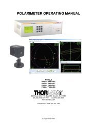
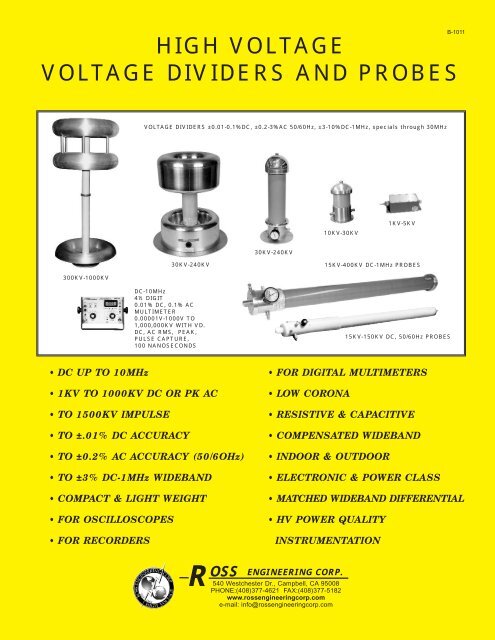
<strong>HIGH</strong> <strong>VOLTAGE</strong><br />
<strong>VOLTAGE</strong> <strong>DIVIDERS</strong> <strong>AND</strong> <strong>PROBES</strong><br />
<strong>VOLTAGE</strong> <strong>DIVIDERS</strong> ±0.01-0.1%DC, ±0.2-3%AC 50/60Hz, ±3-10%DC-1MHz, specials through 30MHz<br />
10KV-30KV<br />
1KV-5KV<br />
30KV-240KV<br />
30KV-240KV<br />
15KV-400KV DC-1MHz <strong>PROBES</strong><br />
300KV-1000KV<br />
DC-10MHz<br />
4½ DIGIT<br />
0.01% DC, 0.1% AC<br />
MULTIMETER<br />
0.00001V-1000V TO<br />
1,000,000KV WITH VD.<br />
DC, AC RMS, PEAK,<br />
PULSE CAPTURE,<br />
100 NANOSECONDS<br />
15KV-150KV DC, 50/60Hz <strong>PROBES</strong><br />
• DC UP TO 10MHz<br />
• 1KV TO 1000KV DC OR PK AC<br />
• TO 1500KV IMPULSE<br />
• TO ±.01% DC ACCURACY<br />
• TO ±0.2% AC ACCURACY (50/6OHz)<br />
• TO ±3% DC-1MHz WIDEB<strong>AND</strong><br />
• COMPACT & LIGHT WEIGHT<br />
• FOR OSCILLOSCOPES<br />
• FOR RECORDERS<br />
• FOR DIGITAL MULTIMETERS<br />
• LOW CORONA<br />
• RESISTIVE & CAPACITIVE<br />
• COMPENSATED WIDEB<strong>AND</strong><br />
• INDOOR & OUTDOOR<br />
• ELECTRONIC & POWER CLASS<br />
• MATCHED WIDEB<strong>AND</strong> DIFFERENTIAL<br />
• HV POWER QUALITY<br />
INSTRUMENTATION<br />
R<br />
OSS<br />
540 Westchester Dr., Campbell, CA 95008<br />
PHONE:(408)377-4621 FAX:(408)377-5182<br />
www.rossengineeringcorp.com<br />
e-mail: info@rossengineeringcorp.com<br />
ENGINEERING CORP.
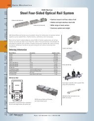
APPLICATION DATA<br />
CAUTION: For best AC accuracy HV clearances should be a radius equal<br />
to twice the height of the unshielded divider. HV withstand clearance should<br />
be at least 1 inch (2.54cm) for each 5KV to 10KV for DC or peak AC (RMS<br />
x 1.414), to nearest HV or ground. Maximum operating voltages are limited<br />
by voltage withstand of internal components, external flashover withstand<br />
and temperature rise limits of types with resistive components. On lower<br />
resistance units, steady state DC and PK AC may be limited to less than the<br />
rated peak short time operating voltage. For withstand test purposes, an<br />
impulse rating is also given to indicate the safety factor for transients above<br />
rated maximum operating PK voltage which could occur unintentionally.<br />
Flashovers may destroy attached measuring and display equipment and<br />
endanger personnel associated with it. Therefore safety factors must be<br />
observed.<br />
If in a confined area with proximity clearances marginal, the AC divider<br />
should be calibrated in place or in a simulated area. DC accuracy is not<br />
affected unless corona is present.<br />
For best results when working with fast rise time pulses (particularly 10<br />
usec or less) a single, common, system ground plane should be used at the<br />
base of the voltage divider. Display or recording equipment, cables<br />
attached to the output of the voltage divider, and personnel near the<br />
equipment should be isolated from conductive surfaces or leads with a<br />
minimum of capacitance to ground to prevent multiple ground returns which<br />
can distort the signal. Where output cable is longer than 20ft, or load is low<br />
impedance, Ross fiber optic transmission systems or cable driver 50 or 75<br />
ohm matching amplifiers are available.<br />
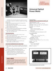
Versatility, Wideband And High Accuracy: Ross Engineering<br />
Corporation’s lightweight, base-mounted high voltage dividers or hand-held<br />
probes are designed for use from 1KV to 1000KV with accuracies of 0.01<br />
% to 3% DC, 0.2% to 10% AC with some model bandwidths to over 20MHz,<br />
or pulse to 10 nanosecond rise times. They can be used at any attitude and<br />
many are self-supporting up to 10G’s shock. They are available in<br />
compensated resistance-capacitance types or uncompensated resistive or<br />
capacitive types. Applications include use with panel meters, recorders,<br />
digital voltmeters, oscilloscopes, or computers for viewing and recording<br />
DC, CW (Continuous Wave), AC, pulse, or modulated frequencies. They<br />
can also be used as simple, high-accuracy meter multipliers.<br />
High voltage resistances are usually 2 megohms or 4 megohms per KV to<br />
minimize heating and voltage coefficients consistent with compact sizes.<br />
High Voltage resistances of 50 ohms or less and as high as 1000 megohms<br />
or more per KV are available. High voltage capacitance is usually<br />
maintained at low picofarad values to minimize circuit effects.<br />
DC and 60Hz calibration is traceable to the N.I.S.T. Units are matched for<br />
1 megohm, 20 to 50pF typical oscilloscope input impedance or other<br />
instrumentation impedances as required, with up to 20 feet (please specify<br />
length, the shorter the better for optimum frequency response) of RG59<br />
coaxial cable or special Ross Engineering Corporation coaxial cable. For<br />
longer wide-band distances, fiber optic or 50 or 75 ohm coaxial<br />
transmission can be supplied for up to 1 kilometer or more. Ross's fiber<br />
optic transmission systems are ideal for full isolation to eliminate multiple<br />
ground paths or pick-up at the instrumentation level. High voltage<br />
terminations are designed for minimum corona. For units with ratings at<br />
very high voltage, additional corona and grading rings or toroids are<br />
utilized, further minimizing corona and maintaining proper voltage<br />
distribution. Insulating surfaces are sealed with anti-track, moistureresistant<br />
material for further corona reduction and environmental protection.<br />
Although the Ross voltage dividers can be ordered for use in oil or other<br />
atmosphere, the standard models are designed for use indoors or outdoors<br />
in air. Each model is hermetically sealed and filled with a non-toxic<br />
insulating gas at low pressure to exclude moisture. The high dielectric<br />
strength of the gas makes it ideal for use in voltage dividers. More<br />
desirable than heavy solid encapsulation, insulating gas minimizes internal<br />
corona by eliminating the possibility of isolated voids or bubbles which<br />
could occur if internal components were potted in solid material. Gas also<br />
eliminates the weight and less stable dielectric constants and losses of oil,<br />
other liquids, or solids, and allows easy dismantling for modification or<br />
repair if required. Ross can supply a gas refill kit if needed. See brochure<br />
B-1010 and B-1012-A for additional use with digital multimeter or digital<br />
panel meter. See brochure B-1020-B for fiber optic transmission systems,<br />
or B-1020 for coaxial cable drivers, and matching systems.<br />
Voltage Ratings: Standard maximum operating voltages are from 3KV<br />
to 1000KV DC or PK AC, and to 1,500KV impulse, in steps of 2KV to 15KV.<br />
It should be noted that transient and intermittent single short pulse<br />
operating voltage can be 50% or more beyond the low frequency or DC<br />
steady-state rating, depending on the type of divider.<br />
Derating for CW RF: With frequencies above 100KHz, steady state CW<br />
(Continuous Wave) voltage derating depends on the type of compensating<br />
capacitors and the type of insulation. Maximum RF voltage operation is<br />
2<br />
<strong>HIGH</strong> <strong>VOLTAGE</strong> <strong>VOLTAGE</strong> <strong>DIVIDERS</strong> <strong>AND</strong> <strong>PROBES</strong><br />
R<br />
generally limited by dielectric heating of insulation, therefore, units with<br />
special insulation are available for CW at these higher frequencies. Please<br />
inquire about special insulation if your application may require its use.<br />
See also “HV Divider and Probes proximity effects and HV clearances”<br />
Multimeters, Oscilloscopes, Power Quality Recorders, Fiber<br />
Optic Transmitters, 50 or 75 Ohm Matching Amplifiers and<br />
Instrumentation Systems: Ross Engineering Corporation can supply<br />
wide-band DC-1MHz fiber optic, or coaxial transmission DC to over 35MHz<br />
and matched recorder or display systems to provide you with a complete<br />
measurement or display system. Please see brochures: B-1010, B-1010-<br />
A, B-1012-A Digital Multimeters,B-1020 Matching Amplifiers and B-1020-B<br />
Fiber Optic Transmission Systems for more information on our<br />
transmission, display, and recorder systems.<br />
Accuracy and Stability: Accuracy and stability in standard Ross voltage<br />
divider units is generally better than ±0.1% DC, ±0.5% 50/60Hz, and 3% to<br />
10% to 1MHz-10MHz, at better than 30PPM/ºC Temperature coefficient<br />
and 0.1 to 0.5PPM/V Voltage coefficient. Accuracies to 0.01% DC at less<br />
than 5PPMTC, low voltage coefficients and 0.2% AC or better (over specific<br />
frequencies) available on many models. See brochure B-1011-B.<br />
Calibration charts related to N.I.S.T. can be furnished for each 10% or 20%<br />
Voltage Point to allow Correction factors to better than 0.1%, or better than<br />
0.01% for the 0.01% types, Frequency charts DC-20MHz are available as<br />
well as temperature stability (drift) with warm-up time. Useful frequency<br />
response is generally DC to 5MHz (to 10MHz and up to 20MHz on some<br />
models) with 250 to 10 nanosecond rise times. Wide-band accuracy is<br />
generally better than 3% to 10% over the frequency range, but can be to<br />
0.2% or better at some specific frequencies and with proper proximity or<br />
shielding. Phase shift is generally minimal below 100KHz for wide-band<br />
types and negligible at 60Hz.<br />
For highest accuracy in high impedance, low input capacitance types,<br />
consideration must be given to induced voltage pick-up in leads, contact<br />
potential, corona, effective capacitance, and voltage gradient and<br />
capacitance shift related to proximity to high voltage sources, ground<br />
planes, walls, enclosures, and loads. Preferably the divider should be<br />
calibrated with the specific instrument being used and specific proximities if<br />
extreme accuracy is required, Greatest accuracy, particularly AC accuracy,<br />
is attained with proper ground plane and if maximum clearance to<br />
conductive materials, which can cause capacitance variation and corona. If<br />
available, user's proximity dimensions will be simulated when calibrating.<br />
Maximum accuracy is centered around two-thirds to three-quarters of the<br />
DC or PK AC rating, unless otherwise requested. For higher frequencies,<br />
the lower capacitance, lower ratio models with shortest output cables have<br />
fewer resonances above 1MHz, but proximity effects are greater and must<br />
be considered for best AC accuracy and wave shape transfer. If larger<br />
diameters are allowable, special shields are available to eliminate proximity<br />
variations for extremely high accuracy AC or pulse wave shape<br />
requirements and to provide better voltage grading. Operating<br />
temperatures range from -80ºC to +65ºC ambient. Some units can be built<br />
to withstand up to +75ºC ambient and vibration and shock of up to 50G's or<br />
more.<br />
Ratio and Loading: In the standard 1000/1 or 10,000/1 Ross voltage<br />
dividers the low voltage capacitors and resistors are selected to provide<br />
correct ratios when shunted by 1 megohm, 20-50pF oscilloscope (or other<br />
load), plus 2, 3, 6, 15, or 20 feet (please specify the shortest practicable<br />
length) of low capacitance RG59 or special Ross Engineering Corporation<br />
coaxial cable unless otherwise required. Standard cable lengths are 3 or 6<br />
feet for 15KV or 30KV dividers, 15 feet for dividers above 30KV, For the<br />
compact types, with metal oxide resistors, DC ratio is generally stable within<br />
better than 0.1% to 1% in an operating range of over 80 degrees C ambient<br />
temperature change for most models, and even better than 3-5 PPM/ºC<br />
(0.0003%) for most high accuracy types. In 0.1% dividers with less than 4<br />
megohms per KV, units can drift up to 0.1% - 0.3% as they warm up when<br />
used continuously at maximum rating, less at below maximum rating.<br />
However, repeatability remains at 0.1% after stabilizing. The actual voltage<br />
divider ratio is determined by the following formula:<br />
R 1 (1+ω 2 C 2 2 R 2<br />
2) ½ N= voltage ratio R 2 = low end effective res.<br />
N= +1 ω= 2Πƒ C 1 = high end effective capacitance<br />
R 2 (1+ω 2 C 2 1 R 1<br />
2) ½ R 1 =high end res. C 2 = low end effective capacitance<br />
If the high voltage input resistance is high and the HV capacitance and ratio<br />
selected are low, normal external and added load capacitance including<br />
coaxial cable and resistance of many display or recording devices can<br />
seriously affect the ratios. The relationships in the ratio formula will indicate<br />
where and to what extent low frequency response or ratio becomes<br />
affected. Special ratios, capacitances, and resistances are available to<br />
satisfy most matching problems, however output cable length and<br />
instrumentation load must always be considered.<br />
OSS<br />
540 Westchester Dr., Campbell, CA 95008<br />
PHONE:(408)377-4621 FAX:(408)377-5182<br />
www.rossengineeringcorp.com<br />
e-mail: info@rossengineeringcorp.com<br />
ENGINEERING CORP.
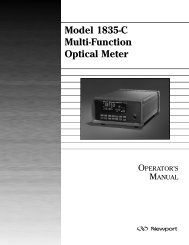
WIDEB<strong>AND</strong> VD SERIES<br />
These compact, high impedance resistance-capacitance type high voltage dividers<br />
are frequency compensated from DC to above 1MHz, some to 5, 10 and 20MHz.<br />
They have properly matched resistive and capacitive elements, and retain excellent<br />
accuracy under fixed or portable applications. Each can be used when matched<br />
with proper frequency response panel meter, power quality recorder, digital multimeter,<br />
or oscilloscope for measuring, viewing, or recording DC, AC, pulse, and modulated<br />
frequencies (see brochure B-1010 and B-1012).<br />
TYPICAL UNITS - MANY OTHERS AVAILABLE BASE MOUNTED RESISTANCE - CAPACITANCE TYPE, COMPENSATED WIDEB<strong>AND</strong><br />
VD900-20-D- 900KV<br />
0.5 3 0.5<br />
DC-1MHz 1,450KV 1,800 - 20 1,000/1/20,000/1<br />
VD900-20-T-<br />
900KV<br />
0.5 3 0.5<br />
DC-1MHz 1,450KV 1,800 - 20 1,000/1/20,000/1<br />
VD1000-18-T- 1,000KV 0.5 3 0.5 DC-1MHz 1,550KV 2,000 - 18 1,000/1/20,000/1<br />
VD60-12.5-B-<br />
VD60-6.2-B-<br />
VD60-6.2-A-<br />
60KV<br />
60KV<br />
60KV<br />
0.1<br />
0.1<br />
0.1<br />
0.5<br />
0.5<br />
0.5<br />
0.1<br />
0.1<br />
0.1<br />
Most units are designed for indoor use in air, however, special units are available for<br />
use in oil, other atmospheres, or outdoors. For fast rise time, low duty cycle and<br />
high power pulse work, low HV impedances of 50Ω to 10KΩ are available. Special<br />
extra high accuracy 0.01% DC with less than 5PPMTC (0.0005%) or 0.2% AC or<br />
better (with special external shielding) units are available. Calibration charts are<br />
supplied.<br />
DC-2MHz<br />
DC-2MHz<br />
DC-2MHz<br />
120KV<br />
120KV<br />
120KV<br />
120<br />
120<br />
120<br />
240<br />
240<br />
240<br />
12.5<br />
6.2<br />
6.2<br />
1,000/1<br />
1,000/1<br />
1,000/1<br />
VD75-10-C-<br />
*VD75-5-A-<br />
*VD75-5-C-<br />
75KV<br />
75KV<br />
75KV<br />
0.1<br />
0.1<br />
0.1<br />
0.5<br />
1<br />
1<br />
0.1<br />
0.1<br />
0.1<br />
DC-1MHz<br />
DC-1MHz<br />
DC-1MHz<br />
150KV<br />
150KV<br />
150KV<br />
150<br />
150<br />
150<br />
300<br />
300<br />
300<br />
10<br />
5<br />
5<br />
1,000/1<br />
1,000/1<br />
1,000/1<br />
VD90-8.3-A-<br />
*VD90-8.3-B-<br />
*VD90-8.3-C-<br />
90KV<br />
90KV<br />
90KV<br />
0.1<br />
0.1<br />
0.1<br />
1<br />
1<br />
1<br />
0.1<br />
0.1<br />
0.1<br />
DC-1MHz<br />
DC-1MHz<br />
DC-1MHz<br />
180KV<br />
180KV<br />
180KV<br />
180<br />
180<br />
180<br />
360<br />
360<br />
360<br />
8.3<br />
8.3<br />
8.3<br />
1,000/1<br />
1,000/1<br />
1,000/1<br />
*<br />
**<br />
VD150-10-C-<br />
VD150-10-T-<br />
*VD150-2.5-B-<br />
VD120-12.5-B-<br />
VD120-12.5-T-<br />
VD120-12.5-C-<br />
VD120-6.2-A-<br />
*VD120-3.1-A-<br />
*VD120-3.1-B-<br />
*VD120-3.1-T-<br />
*VD120-3.1-C-<br />
120KV<br />
120KV<br />
120KV<br />
120KV<br />
120KV<br />
120KV<br />
120KV<br />
120KV<br />
150KV<br />
150KV<br />
150KV<br />
240KV<br />
240KV<br />
240KV<br />
240KV<br />
300KV<br />
300KV<br />
450KV<br />
450KV<br />
450KV<br />
0.1<br />
0.1<br />
0.1<br />
0.1<br />
0.1<br />
0.1<br />
0.1<br />
0.1<br />
0.1<br />
0.1<br />
0.1<br />
0.1<br />
0.1<br />
0.1<br />
0.1<br />
0.2<br />
0.2<br />
0.5<br />
0.5<br />
0.5<br />
0.5<br />
0.5<br />
0.5<br />
1<br />
1<br />
1<br />
1<br />
1<br />
0.5<br />
0.5<br />
2<br />
0.5<br />
2<br />
5<br />
3<br />
1<br />
3<br />
2<br />
2<br />
3<br />
0.1<br />
0.1<br />
0.1<br />
0.1<br />
0.1<br />
0.1<br />
0.1<br />
0.1<br />
0.1<br />
0.1<br />
0.1<br />
0.1<br />
0.1<br />
0.1<br />
0.1<br />
0.2<br />
0.2<br />
0.3<br />
0.3<br />
0.3<br />
DC-1MHz<br />
DC-1MHz<br />
DC-1MHz<br />
DC-1MHz<br />
DC-1MHz<br />
DC-1MHz<br />
DC-1MHz<br />
DC-1MHz<br />
DC-1MHz<br />
DC-1MHz<br />
*DC<br />
DC-1MHz<br />
DC-1MHz<br />
*DC<br />
*DC<br />
DC-1MHz<br />
*DC<br />
DC-1MHz<br />
DC-1MHz<br />
DC-1MHz<br />
240KV<br />
240KV<br />
240KV<br />
240KV<br />
240KV<br />
240KV<br />
240KV<br />
240KV<br />
280KV<br />
280KV<br />
280KV<br />
450KV<br />
450KV<br />
450KV<br />
450KV<br />
550KV<br />
550KV<br />
850KV<br />
850KV<br />
850KV<br />
MAXIMUM OPERATE *RATIO ACCURACY, SPECIFIED<br />
ELECTRONIC ST<strong>AND</strong>ARD NOMINAL HV ***ST<strong>AND</strong>ARD RATIO<br />
**DC OR PK 60Hz CONDITIONS <strong>AND</strong> PROXIMITY.<br />
CONTINUOUS<br />
WITH CAL CHART<br />
*NORMAL<br />
CLASS MAX IMPUT **IMPEDANCE TO LOAD OF 1MΩ<br />
TEST<br />
50pF <strong>AND</strong> SPECIAL<br />
MODEL<br />
FREQUENCY<br />
WITHOUT COOLING<br />
IMPULSE RESISTANCE<br />
+<br />
RANGE<br />
NOMINAL ROSS COAXIAL RG59<br />
STD 2 OR 4MΩ<br />
DC 60Hz STABILITY<br />
1X50uSEC MEGOHMS<br />
CAPACITANCE CABLE. 6’ TO 30KV,<br />
% AC% %<br />
OR MORE PER KV<br />
PULSE 2M/KV 4M/KV PF 15’ ABOVE 30KV<br />
VD5-15-DH- 5KV 0.1 0.5 0.1 DC-5MHz 10KV 10 20 15 1,000/1<br />
VD15-8.3-A-<br />
15KV 0.1 0.5 0.1 DC-5MHz 30KV 30 60 8.3 1,000/1<br />
VD30-12.5-A- 30KV<br />
0.1 0.5 0.1<br />
DC-5MHz<br />
45KV 60 120 12.5 1,000/1<br />
VD30-8.3-A-<br />
30KV<br />
0.1 0.5 0.1<br />
DC-5MHz<br />
60KV 60 120 8.3<br />
1,000/1<br />
*VD30-4.1-A-<br />
30KV<br />
0.1 1 0.1<br />
DC-5MHz<br />
60KV 60 120 4.1<br />
1,000/1<br />
VD45-8.3-A-<br />
45KV<br />
0.1 0.5 0.1 DC-2MHz 90KV 90 180 8.3 1,000/1<br />
VD50-8.3-AC-<br />
*VD50-4.1-AC-<br />
50KV PULSE<br />
50KV PULSE<br />
0.1<br />
0.1<br />
0.5<br />
1<br />
0.1<br />
0.1<br />
DC-5MHz<br />
DC-5MHz<br />
60KV<br />
60KV<br />
100<br />
100<br />
200<br />
200<br />
8.3<br />
4.1<br />
1,000/1<br />
1,000/1<br />
*VD195-7.7-B- 195KV<br />
0.1 1 0.1<br />
DC-1MHz<br />
350KV 390 780 7.7 1,000/1/10,000/1<br />
*VD195-7.7-C- 195KV<br />
0.1 1 0.1<br />
DC-1MHz<br />
350KV 390 780 7.7 1,000/1/10,000/1<br />
VD225-40-T- 225KV 0.1 1 0.1 DC-1MHz 400KV 450 900 40 1,000/1/10,000/1<br />
VD240-37-C-<br />
VD240-6.2-C-<br />
*VD240-1.5-B-<br />
*VD240-1.5-C-<br />
VD300-30-D-<br />
*VD300-1.2-D-<br />
VD450-40-D-<br />
VD450-40-T-<br />
VD450-20-D-<br />
240<br />
240<br />
240<br />
240<br />
240<br />
240<br />
240<br />
240<br />
300<br />
300<br />
300<br />
480<br />
480<br />
480<br />
480<br />
600<br />
600<br />
900<br />
900<br />
900<br />
480<br />
480<br />
480<br />
480<br />
480<br />
480<br />
480<br />
480<br />
600<br />
600<br />
600<br />
960<br />
960<br />
960<br />
960<br />
1200<br />
1200<br />
1800<br />
1800<br />
1800<br />
12.5<br />
12.5<br />
12.5<br />
6.2<br />
3.1<br />
3.1<br />
3.1<br />
3.1<br />
10<br />
10<br />
2.5<br />
37<br />
6.2<br />
1.5<br />
1.5<br />
30<br />
1.2<br />
40<br />
40<br />
20<br />
1,000/1<br />
1,000/1<br />
1,000/1<br />
1,000/1<br />
1,000/1<br />
1,000/1<br />
1,000/1<br />
1,000/1<br />
1,000/1/10,000/1<br />
1,000/1/10,000/1<br />
1,000/1/10,000/1 •<br />
•<br />
•<br />
1,000/1/10,000/1<br />
1,000/1/10,000/1<br />
1,000/1/10,000/1<br />
1,000/1/10,000/1 •<br />
1,000/1/10,000/1<br />
1,000/1/10,000/1 •<br />
1,000/1/10,000/1<br />
1,000/1/10,000/1<br />
1,000/1/10,000/1 •<br />
•<br />
•<br />
Many units will have frequency response better than ±3% to ±10% over the normal frequency range specified, but some units will only meet a ±3dB specification. Some untis can have better high frequency response if a wider tolerance<br />
(chart correctable) at 50 or 60Hz can be tolerated. Extended frequency response may require a different coaxial cable, a top grading shield and sometimes a bottom shield also. Optimum response may require a small accessory<br />
box at one end or both ends of the coaxial cable. Some units can meet ±3% to 20MHz by using some or all of the above solutions. Low frequency response and proximity effects can be improved by using higher input capacitance<br />
but with the possibility of increased resonance at lower than normal frequencies, (requiring special filters at additional cost) or by greater shielding, by limiting proximity of conductive materials, and by calibrating in place with<br />
proper matching. Units with lower input capacitance normally have fewer resonances and may be more desirable and still sufficiently accurate for most applications if proximity rules are observed. Calibration correction charts and<br />
certification to NIST standards are supplied.<br />
Other input resistances and ratios are available. 2MΩ per KV and 4MΩ per KV are standard which will allow continuous DC operation without excessive heating and drift at PK rating. 1MΩ per KV is an option, but continuous DC or<br />
AC is limited to 1/2 the PK rating. Over 1,000 megohms per KV is available for minimum circuit loading. DC to 1MHz fiber optic system for complete isolation, or 50 or 75 ohm coaxial cable matching battery/AC operated amplifiers<br />
and transmission systems are available for driving coaxial cables longer than 20ft, or low impedance loads. Ross standard fiber optic systems are suitable to 1 kilometer at 1MHz.<br />
*** Special ratios, loads, and cable lengths and types may be specified. For optimum frequency response the coaxial cable should be as short as practicable. For distances of over 20ft a fiber optic system or a 50-75 ohm impedance<br />
cable driver will normally improve the overall frequency response with long cables. Loads with low impedance require higher ratios.<br />
• Optional Std. ratios. Lower ratios may not be feasible depending on load impedance. 1000/1 is commonly used with 10 Megohm input digital meters, with a 2/1 to 10/1 additional accessory box to make 2,000/1 to 10,000/1 into a 1<br />
Megohm oscilloscope.<br />
+<br />
'A' models are minimum size. 'B' models are larger size, 'C' and 'D' models are largest and have extensive voltage grading, external shielding, and large corona shields for minimum corona also to minimize proximity sensitivity and<br />
have better frequency accuracy. -'T' models are weatherproof outdoor units with high strength stack-able skirted housings. Most units are hermetically sealed and also filled with low pressure insulating gas to minimize moisture and<br />
corona, although most can be filled with dry air or nitrogen if necessary, and are generally safe to use even if the insulating gas pressure is zero, as long as no moisture is allowed to enter.<br />
RF current is limited by dielectric heating effects. With special insulation and components, allowable CW RF voltage and current can be higher. Low duty cycle pulse currents can be considerably higher, within the limits of PK operating<br />
voltage and frequency.<br />
Specifications are for reference only and are subject to change. Contact Ross Engineering Corporation for current dimensions.<br />
R<br />
OSS<br />
540 Westchester Dr., Campbell, CA 95008<br />
PHONE:(408)377-4621 FAX:(408)377-5182<br />
www.rossengineeringcorp.com<br />
e-mail: info@rossengineeringcorp.com<br />
ENGINEERING CORP.<br />
3
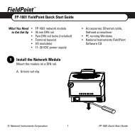
VD1000-T<br />
*AVAILABLE IN 15KV STEPS AT<br />
APPROXIMATELY 2.3” PER STEP.<br />
Specifications are for reference only and<br />
are subject to change. Contact Ross<br />
Engineering Corporation for current<br />
dimensions.<br />
4<br />
MODEL<br />
VD450-T<br />
DIMENSIONS<br />
TYPE<br />
VD5- 0<br />
VD15-A 1<br />
VD30-A 1<br />
VD30-B 2<br />
VD45-A 1<br />
VD50-AC 1<br />
VD60-A<br />
1A<br />
VD60-B 2<br />
VD60-AKB 3<br />
VD75-A<br />
1A<br />
VD75-AKB 3<br />
VD90-A<br />
1A<br />
VD90-AKB 3<br />
VD120-A<br />
VD120-AK<br />
VD120-B<br />
VD120-BT<br />
VD120-T<br />
VD150-B<br />
1A<br />
3A<br />
2A<br />
2B<br />
VD150-C 4<br />
VD150-T<br />
VD195-B<br />
2B<br />
VD195-C 4<br />
VD225-T<br />
VD240-B<br />
2B<br />
VD240-C 4<br />
VD300-D 6<br />
VD450-D 6<br />
VD900-D 6<br />
PAGE 6<br />
HEIGHT*<br />
A<br />
SEE VIEW<br />
A-A<br />
5.53<br />
(140.4)<br />
8.27<br />
(210.0)<br />
10.9<br />
(276.8)<br />
10.11<br />
(256.7)<br />
8.27<br />
(210.0)<br />
12.01<br />
(305.0)<br />
14.88<br />
(377.9)<br />
14.81<br />
(376.1)<br />
15.25<br />
(387.3)<br />
17.19<br />
(256.7)<br />
18.94<br />
(481.0)<br />
19.50<br />
(495.3)<br />
21.88<br />
(555.7)<br />
22.83<br />
(579.8)<br />
24.39<br />
(619.5)<br />
PAGE 6<br />
PAGE 6<br />
PAGE 6<br />
PAGE 6<br />
VD900-T PAGE 6<br />
PAGE 6<br />
29.05<br />
(737.8)<br />
27.5<br />
(698.5)<br />
36.13<br />
(917.7)<br />
34.53<br />
(877.0)<br />
43.09<br />
(1094.4)<br />
41.46<br />
(1053.0)<br />
70.12<br />
(1781.0)<br />
110.5<br />
(2806.7)<br />
236.00<br />
(5994.4)<br />
OPTIONAL<br />
PRESSURE<br />
GAUGE<br />
TYPE 0<br />
VALVE<br />
.97<br />
(24.6)<br />
TYPE 0<br />
1.750<br />
(44.45)<br />
2.64<br />
(67.1)<br />
0.187"HV<br />
TERMINAL<br />
6-32 STUD<br />
1.71<br />
(43.4)<br />
5.25<br />
(133.4)<br />
.77<br />
(19.6)<br />
.91<br />
(23.1)<br />
1.32<br />
(33.5) VIEW A-A<br />
VD5<br />
.12<br />
(3.0)<br />
3.15<br />
(80.0)<br />
3.50<br />
(88.9)<br />
HV TERM 1/4-28UNF<br />
PHMS X .50(12.7)<br />
A± .38<br />
(9.6)<br />
BNC<br />
OUTPUT<br />
10-32 UNF<br />
GROUND<br />
TERMINAL<br />
.171 (4.3) DIA MOUNTING HOLES<br />
4PL EQ SP ON 3.125 (79.3) DIA BC<br />
TYPE 1<br />
.218 (5.5) DIA MOUNTING HOLES<br />
4PL EQ SP ON 5.250 (133.3) DIA BC<br />
TYPE 1A<br />
TYPE 1<br />
VD5-DH VD15-A VD60-B VD75-AKB<br />
6.00<br />
(152.4)<br />
R<br />
6.08<br />
(154.4)<br />
PRESSURE<br />
GAUGE<br />
VALVE<br />
.75<br />
(19.0)<br />
.12<br />
(3.0)<br />
TYPE 2<br />
4.750<br />
(120.65)<br />
6.00<br />
(152.4)<br />
TYPE 2<br />
MOUNTING<br />
HOLES 0.203<br />
4PL<br />
3.94<br />
(100.0) HV TERM 1/4-28 UNF<br />
PHMS X .50(12.7)<br />
A± .38<br />
(9.6)<br />
BNC<br />
OUTPUT<br />
1.56 (39.6)<br />
10-32 UNF<br />
GROUND<br />
PRESSURE<br />
GAUGE<br />
VALVE<br />
TERMINAL<br />
.218 (5.5) DIA MOUNTING HOLES<br />
4PL EQ SP ON 5.250 (133.3) DIA BC<br />
.265 (6.7) DIA<br />
MOUNTING<br />
HOLES 4PL EQ<br />
SP ON 14.00<br />
(355.6) DIA BC<br />
TYPE 3<br />
12.00<br />
(304.8)<br />
INCHES<br />
(MILLIMETERS)<br />
15.00<br />
(381.0)<br />
10.00 (254.0) DIA<br />
.265 (6.7) MOUNTING<br />
2A, HOLES 4PL EQ SP ON<br />
3A 9.00 (228.6) DIA BC<br />
TYPE 2A, 2B, 3A TYPE 3<br />
2B<br />
15.00 (381.0) DIA<br />
.265 (6.7) MOUNTING<br />
HOLES 4PL EQ SP ON<br />
14.00 (355.6) DIA BC<br />
OSS<br />
540 Westchester Dr., Campbell, CA 95008<br />
PHONE:(408)377-4621 FAX:(408)377-5182<br />
www.rossengineeringcorp.com<br />
e-mail: info@rossengineeringcorp.com<br />
ENGINEERING CORP.<br />
HV TERM 1/4-28 UNF<br />
PHMS X .75(19.0)<br />
BNC<br />
OUTPUT<br />
TYPE 3A<br />
VD120-AK<br />
A± .75<br />
(19.0)<br />
.12<br />
(3.0)<br />
10-32 UNF<br />
GROUND<br />
TERMINAL
TYPE 4<br />
TYPE 6<br />
VD150-C<br />
VD450-D<br />
27.00<br />
(685.8)<br />
HV TERM 1/4-28 UNF<br />
PHMS X .75 (19.0)<br />
UPPER<br />
SECTION<br />
VALVE<br />
42.00 (1066.8) +<br />
2.00 (50.8)<br />
HV TERM 1/4-28 UNF<br />
PHMS X .75 (19.0)<br />
PRESSURE<br />
GAUGE<br />
A±.75 (19.0)<br />
SEPERABLE INTO TWO<br />
SEALED SECTIONS<br />
PRESSURE<br />
GAUGE<br />
VALVE<br />
OUTPUT BNC<br />
OPENING<br />
2.12 (53.8)<br />
BNC OUTPUT<br />
A±2.00 (50.80)<br />
.12<br />
(3.0)<br />
15.00<br />
(381.0)<br />
.265 (6.7) DIA MOUNTING HOLES<br />
4PL EQ SP ON 14.000 (355.6) DIA BC<br />
INCHES<br />
(MILLIMETERS)<br />
PRESSURE<br />
GAUGE<br />
LOWER<br />
SECTION<br />
VALVE<br />
20.00<br />
(508.0)<br />
.62<br />
(15.7)<br />
TYPE 4<br />
.390 (9.9) DIA MOUNTING HOLES<br />
4PL EQ SP ON 19.250 (488.90) DIA BC<br />
LARGER BASES AVAILABLE<br />
TYPE 6<br />
R<br />
OSS<br />
540 Westchester Dr., Campbell, CA 95008<br />
PHONE:(408)377-4621 FAX:(408)377-5182<br />
www.rossengineeringcorp.com<br />
e-mail: info@rossengineeringcorp.com<br />
ENGINEERING CORP.<br />
5
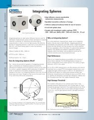
OUTDOOR VD SERIES<br />
These models are designed to be weatherproof for indoor/outdoor use up to 1000KV DC or AC PK.<br />
They are compensated resistance-capacitance wideband DC to 1MHz and are balanced to provide<br />
safe voltage gradients with low capacitance, better high frequency accuracy (if calibrated for proximity<br />
effects), and low corona. The use of low-loss precision ceramic capacitors and exceptionally<br />
stable metal film or wire wound resistors results in stability and accuracies of 0.01% to 3% with temperature<br />
coefficients typically less than 3 PPM/°C to 40 PPM/°C and voltage coefficients from very<br />
low to zero.<br />
Applications include use with panel meters, power quality recorders, digital voltmeters, oscilloscopes<br />
or computers to measure, view and record DC, AC, transient pulse or pulse train and modulated CW.<br />
Ross Engineering Corp. dividers can be used in conjunction with Ross Engineering Corp. AC or<br />
AC/battery operated fiber optic systems or 50 or 75 ohm matching amplifier/coaxial cable drivers to<br />
create complete DC to 1MHz (or more) wideband systems for driving long fiber optic or coaxial<br />
cables. Fiber optics are particularly desirable to eliminate ground current return, pick-up and isolation<br />
problems, although Ross Engineering Corp. coaxial cable drivers provide considerable isolation<br />
between source and load also.<br />
VD900-T<br />
42.00<br />
(1066.8)<br />
INCHES<br />
(MILLIMETERS)<br />
HV TERM 3/8-24 UNF<br />
PHMS X .75(19.0)<br />
24.00<br />
(609.6)<br />
236.11 ± 2.00/VD900<br />
(5997.2) ± (50.80)<br />
258.00 ± 2.00/VD1000<br />
(6553.2) ± (50.80)<br />
HV TERM 3/8-24 UNF<br />
AS REQUIRED<br />
SEPARABLE<br />
INTO TWO OR<br />
FOUR STACKS<br />
288.0 ± 2.00<br />
(7315.2) ± (50.80)<br />
VD900- -T, BTC<br />
VD1,000- -T, BTC<br />
42.00<br />
(1066.8)<br />
HV TERM 3/8-24 UNF<br />
AS REQUIRED<br />
110.50 ± 1.00<br />
(2806.7) ± (25.4)<br />
LOW END<br />
HOUSING<br />
16.88<br />
(428.8)<br />
42.00 ± 2.00<br />
(1066.8)±(50.80)<br />
108.00 ± 2.00<br />
(2743.2) ± (50.80)<br />
VD450-<br />
-T, BTC<br />
SEPARABLE<br />
INTO TWO<br />
STACKS<br />
PRESSURE<br />
GAUGE<br />
OUTPUT<br />
TERMINALS<br />
IN WEATHER<br />
PROOF BOX<br />
PRESSURE<br />
GAUGE<br />
LOW END<br />
HOUSING<br />
OUTPUT<br />
TERMINALS<br />
IN WEATHER<br />
PROOF BOX<br />
11.50<br />
(292.1)<br />
VD60- -T<br />
VD90- -T<br />
VD120- -T<br />
32.00 ± 1.00/VD120<br />
(812.8) ± (25.4)<br />
32.00 ± 1.00/VD150<br />
(812.8) ± (25.4)<br />
58.53 ± 1.00/VD225<br />
(1486.6) ± (25.4)<br />
TANK VALVE<br />
15.50 ± 1.00/VD60-T<br />
(393.7) ± (25.4)<br />
25.00 ± 1.00/VD90-T<br />
(635.0) ± (25.4)<br />
25.00 ± 1.00/VD120-T<br />
(635.0) ± (25.4)<br />
TANK VALVE<br />
VD120-<br />
VD150-<br />
VD225-<br />
HV TERM 3/8-24 UNF<br />
PHMS X .75(19.0)<br />
-TC<br />
-BTC<br />
-BTC<br />
* ENCLOSED OPTIONAL COAXIAL OR FIBER OPTIC<br />
DRIVER / TRANSMITTER<br />
6<br />
R<br />
OSS<br />
540 Westchester Dr., Campbell, CA 95008<br />
PHONE:(408)377-4621 FAX:(408)377-5182<br />
www.rossengineeringcorp.com<br />
e-mail: info@rossengineeringcorp.com<br />
ENGINEERING CORP.
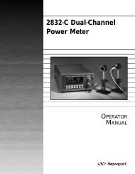
VMP PROBE SERIES<br />
(Please see also digital multimeter and VM probes brochure B-1010 or B-1012-A for<br />
multiple match and multiple ratio to match digital voltmeters and accessories.) The<br />
Ross VMP HV probes are designed for hand-held portable applications with insulated<br />
handle, or mounting in a fixed position. The portable capacitive, resistive, or<br />
compensated types are used with digital multimeters, oscilloscopes, and various<br />
types of panel meters. Resistive types are used primarily for DC and 50 or 60Hz AC<br />
or other specific single frequency sine wave, while the capacitive types are used for<br />
wideband and pulse work. Compensated resistance/capacitance wideband DC to<br />
1MHz (or more) models are preferred for general use In both the VMP and VD<br />
Series.<br />
Standard calibration is centered around 2/3 to 3/4 of the maximum rating and is<br />
matched for 1 megohm, 20 to 50pF or 10 megohms 75-100pF of load input impedance<br />
of display or recording device and optional 3, 6, or 15 feet (please specify the<br />
shortest practicable length) of RG-59 or special Ross Engineering Corporation<br />
VMP200A<br />
WIDEB<strong>AND</strong> DC-1MHz<br />
VMP60-G DC & 50/60Hz<br />
coaxial cable. Fiber optic system or 50-75 ohm matching amplifier/coaxial cable driver<br />
is recommended for wide-band transmission over 20 feet. Any type can be calibrated<br />
with best accuracy and specified stability at specific frequencies, voltages<br />
and loads within their capabilities. Unless rules of shielding and proximity are followed,<br />
VMP series models may not be as accurate as the VD models due to wider<br />
variation in possible proximity of walls, equipment, etc. Other ratios and matchings<br />
are available.<br />
MODEL<br />
ELECTRONIC<br />
CLASS<br />
MODEL<br />
POWER<br />
CLASS<br />
VMP30E-G VMP15-G<br />
VMP30EA-25Y-H VMP15-25Y-H<br />
VMP30-G<br />
VMP30-12.5Y-H<br />
VMP60-G<br />
VMP60-8.3Y-H<br />
KV MAXIMUM<br />
OPERATE<br />
CONTINUOUS<br />
ELEC -<br />
TRONIC<br />
CLASS DC<br />
OR PK AC<br />
30KV<br />
30KV<br />
60KV<br />
60KV<br />
90KV<br />
90KV<br />
120KV<br />
120KV<br />
150KV<br />
150KV<br />
SEE BROCHURE B-1012-A FOR INSULATED H<strong>AND</strong>LES FOR H<strong>AND</strong> HELD REQUIREMENTS.<br />
TYPICAL UNITS - MANY OTHERS AVAILABLE SPECIFICATIONS HV PROBE TYPE <strong>VOLTAGE</strong> DIVIDER OR SERIES MULTIPLIER<br />
•<br />
• MODEL<br />
•<br />
NOMINAL HV INPUT<br />
VMP60E-G<br />
VMP60EA-12.5Y-H<br />
VMP90E-G<br />
VMP90EA-8.3Y-H<br />
VMP120-G<br />
VMP120A-6.2Y-H<br />
VMP150-G<br />
VMP150A-10Y-H<br />
VMP200A-7.6Y-H<br />
POWER<br />
CLASS<br />
RMS L-L<br />
5KV<br />
5KV<br />
8.25KV<br />
8.25KV<br />
25.8KV<br />
25.8KV<br />
38KV<br />
38KV<br />
48KV<br />
48KV<br />
* KV<br />
BEST<br />
ACCURACY<br />
20KV<br />
20KV<br />
45KV<br />
45KV<br />
60KV<br />
60KV<br />
80KV<br />
80KV<br />
100KV<br />
100KV<br />
* ACCURACY<br />
±%<br />
DC<br />
%<br />
.1<br />
.1<br />
.1<br />
.1<br />
.1<br />
.1<br />
.1<br />
.1<br />
.1<br />
.1<br />
*50<br />
OR<br />
60Hz<br />
%<br />
1<br />
1<br />
1<br />
1<br />
1<br />
1<br />
1<br />
1<br />
1<br />
1<br />
*WIDE-<br />
B<strong>AND</strong><br />
%<br />
-<br />
3dB<br />
-<br />
3dB<br />
-<br />
3dB<br />
-<br />
3dB<br />
-<br />
3dB<br />
NORMAL<br />
FREQUENCY<br />
RANGE<br />
DC, 50/60Hz<br />
DC-1MHz<br />
DC, 50/60Hz<br />
DC-1MHz<br />
DC, 50/60Hz<br />
DC-1MHz<br />
DC, 50/60Hz<br />
DC-1MHz<br />
DC, 50/60Hz<br />
DC-1MHz<br />
KV<br />
MAXIMUM<br />
IMPULSE<br />
1.2X50<br />
uSEC<br />
TEST<br />
SINGLE PULSE<br />
60KV<br />
60KV<br />
120KV<br />
120KV<br />
150KV<br />
150KV<br />
200KV<br />
200KV<br />
250KV<br />
250KV<br />
RESISTANCE<br />
MEGOHMS<br />
300<br />
300<br />
600<br />
600<br />
900<br />
900<br />
1200<br />
1200<br />
1500<br />
1500<br />
CAPACITANCE<br />
PF NORMAL<br />
RES ONLY<br />
25<br />
RES ONLY<br />
12.5<br />
RES ONLY<br />
8.3<br />
RES ONLY<br />
6.2<br />
RES ONLY<br />
10<br />
** ST<strong>AND</strong>ARD RATIO TO<br />
LOAD <strong>AND</strong> 15’ SPECIAL<br />
ROSS COAX CABLE.<br />
10MΩ<br />
100pF<br />
1,000/1<br />
1,000/1<br />
1,000/1<br />
1,000/1<br />
1,000/1<br />
1,000/1<br />
1,000/1<br />
1,000/1<br />
1,000/1<br />
1,000/1<br />
200KV 72KV 150KV .1 1 3dB DC-1MHz 300KV 1950 7.6 1,000/1 10,000/1 7’0”<br />
LOAD<br />
1MΩ<br />
30pF<br />
1,000/1<br />
1,000/1<br />
1,000/1<br />
1,000/1<br />
10,000/1<br />
10,000/1<br />
10,000/1<br />
10,000/1<br />
10,000/1<br />
10,000/1<br />
OSHA MIN.<br />
CLEAR-<br />
ANCE<br />
2’7”<br />
3’4”<br />
3’4”<br />
3’8”<br />
5’0”<br />
+ RECOMMENDED<br />
MINIMUM<br />
ALLOWABLE<br />
H<strong>AND</strong>LE LENGTH IN FEET<br />
INCLUDING H<strong>AND</strong> HOLD<br />
RECOM-<br />
MENDED<br />
LENGTH<br />
3’11” - 4’7”<br />
4’8” - 5’4”<br />
4’8” - 5’4”<br />
5’0” - 5’7”<br />
6’4” - 6’11”<br />
8’4” - 8’11”<br />
NOM.<br />
POWER<br />
CLASS<br />
6’-9’<br />
7.5’ - 9’<br />
7.5’ - 9’<br />
VMP250A-6.2Y-H<br />
VMP300A-5Y-H<br />
250KV 95KV 187KV .1 2 3dB DC-1MHz 400KV 2400 6.2 1,000/1 10,000/1 7’0”<br />
300KV 121KV 225KV .2 3 3dB DC-1MHz 500KV 3000 5 1,000/1 10,000/1 7’0”<br />
8’4” - 8’11”<br />
8’4” - 8’11”<br />
VMP400A-3.8Y-H<br />
400KV 145KV 300KV .2 5 3dB DC-1MHz 600KV 3900 3.8 1,000/1 10,000/1 11’0”<br />
* With proper proximity of nearby conducting surface and test point size. Accuracy can be<br />
improved by calibrating with known proximity. Accuracy is at 2/3 to 3/4 of max rating unless<br />
otherwise required. Calibration points are every 10 to 20% and are included with instruction<br />
manual. Other calibration points are optional.<br />
* Some probes are subject to limits on frequency, and proximity of HV and conductive surfaces,<br />
to obtain stated accuracies.<br />
** Most standard models are single ratio, single or dual load matching to oscilloscope or DMM.<br />
Higher input resistance or capacitance and other ratios available including multiple matching<br />
and multiple ratios.<br />
• Power class is rated on the basis of 3 phase line to line and BIL (basic impulse level)with high<br />
safety factor. Electronic class is rated on max continuous operate without overheating, but<br />
with less safety factor. Impulse is a test rating only.<br />
INCHES<br />
(MILLIMETERS)<br />
COMPENSATED TYPE<br />
WIDEB<strong>AND</strong><br />
PROBE<br />
RESISTIVE TYPE<br />
DC, 50/60Hz<br />
PROBE<br />
2.76 DIA<br />
(70.00)<br />
HV TERMINAL<br />
1/4-28 UNF<br />
1.25 DIA<br />
(31.7)<br />
.60 (15.2)<br />
10-32 THREAD<br />
OR CORONA NUT<br />
B<br />
A<br />
+ Handle length includes handhold of 12” to 24” based on OSHA regulations. See OSHA Title 8,<br />
Page 390, Table 2940.2.<br />
Insulating handles and heavy superflex insulated ground leads are available.<br />
See brochure B-1010, B-1012, and B-1017 for addditional information on handles, digital probes<br />
and digital displays.<br />
Note: Change -H to -J and -G to -GJ if insulated handles are required. See B-1012A or B-<br />
1017B for recommended handle lengths.<br />
Specifications are for reference only and are subject to change.<br />
Contact Ross Engineering Corporation for current dimensions.<br />
ST<strong>AND</strong>ARD<br />
BNC CONNECTOR<br />
1.50<br />
(38.1)<br />
TANK VALVE<br />
PRESSURE GAUGE<br />
.84<br />
(21.3)<br />
BNC CONNECTOR<br />
10-32 UNF<br />
GROUND STUD<br />
10-32 UNF<br />
GROUND TERMINAL<br />
THIS SIDE<br />
.88<br />
(22.3)<br />
1.66<br />
(42.2)<br />
5/8-11 THREAD<br />
OPTIONAL CABLE<br />
WITH BNC OR<br />
OTHER CONNECTOR<br />
2.75<br />
(69.9)<br />
5/8-11 THREAD<br />
DIMENSIONS<br />
MODEL A B<br />
VMP 15-G<br />
VMP 15-25-H<br />
VMP 30-G<br />
VMP 30-H<br />
VMP 60-G<br />
VMP 60-H<br />
VMP 120-G<br />
VMP 120-H<br />
VMP 150-G<br />
VMP 150-H<br />
VMP 200-H<br />
VMP 250-H<br />
VMP300-H<br />
VMP 400-H<br />
12’4” - 12’11”<br />
12.09<br />
(307.0)<br />
-<br />
-<br />
16.75<br />
(425.4)<br />
-<br />
-<br />
24.00<br />
(609.6)<br />
-<br />
-<br />
31.50<br />
(800.1)<br />
-<br />
-<br />
56.5<br />
(1,435.1)<br />
-<br />
-<br />
-<br />
-<br />
-<br />
-<br />
-<br />
-<br />
-<br />
-<br />
-<br />
-<br />
8.91<br />
(226.3)<br />
-<br />
-<br />
12.91<br />
(327.9)<br />
-<br />
-<br />
16.95<br />
(430.5)<br />
-<br />
-<br />
21.12<br />
(536.9)<br />
-<br />
-<br />
24.68<br />
(626.8)<br />
30.53<br />
(775.4)<br />
33.50<br />
(850.9)<br />
43.46<br />
(1103.8)<br />
-<br />
-<br />
7
<strong>HIGH</strong> <strong>VOLTAGE</strong> DEVICES<br />
RELAYS AC 208V TO 1000KV<br />
SWITCHES DC HV CALIBRATION<br />
MEASUREMENT PULSE ENERGY STORAGE<br />
SAFETY <strong>AND</strong> ACCESSORIES FIBER OPTICS ELECTRONIC <strong>AND</strong> POWER<br />
HV MEGMETER ® HIPOT<br />
HV Insulation Leakage Current &<br />
HV Resistance Measurement Meter.<br />
Portable, battery operated, 12V DC or 115V AC.<br />
0-15KV DC 0.001µA to 260µA or to 1000µA.<br />
0-42KV DC 0.001µA to 100µA or to 400µA.<br />
For testing HV Cables,<br />
HV Insulation &<br />
Vacuum Interrupters<br />
VMT-15, 0-15KV DC<br />
VMT-42, 0-42KV DC<br />
Hi-Z ® POWERCLASS TM HV VOLTMETERS<br />
SAFE POWER LINE USE AC/DC FOR UTILITIES,<br />
CONTRACTORS & EMERGENCY SERVICES<br />
Fully safe, portable, all solid state, 1% to 5%<br />
accuracy. Analog or digital shielded high voltage<br />
measurement with minimum circuit loading. 10V to<br />
100KV AC and DC. Ideal for use with Elbow<br />
capacitance tap voltage test points. For cable test<br />
point or direct line voltage and phasing, or differential<br />
measurement.<br />
<strong>HIGH</strong> CURRENT SWITCHES<br />
Models are available up to 20,000A<br />
continuous, and over 1,700,000A<br />
20µsec pulse, with voltage ratings of<br />
6 volts to 400KV peak test. Many<br />
are air cylinder or motor operated for<br />
high contact force. DC to 1MHz.<br />
HV DIGITAL MULTIMETERS<br />
Wideband DC-10MHz. Portable meters have<br />
accuracies to 0.01% DC, 0.1% 50/60Hz, true RMS,<br />
Avg, True PK, ±PK, PK to PK. 3% to 1MHz,-3dB<br />
10MHz. 0.2 microsecond 1/2 sine single pulse<br />
capture & hold. ±2V 50 ohm<br />
output. 0.00001V-1000V DC or<br />
PK AC and for use with HV<br />
Probes to 400KV and Voltage<br />
Dividers to 1,000,000V.<br />
HV RELAYS<br />
HV relays of the air insulated type<br />
for both low and high current.<br />
This series has ratings from 1 to<br />
600A continuous, 100 to 100,000A<br />
momentary and capacitor discharge.<br />
Peak test voltages from 5<br />
to 300KV. Single or Multipole.<br />
NO, NC, DT or Latching. Auxiliary<br />
contacts optional on all types.<br />
Extended life, and tungsten contacts<br />
also available for high current<br />
closing. Also usable in oil or<br />
insulating gas.<br />
HV WIDEB<strong>AND</strong> <strong>VOLTAGE</strong> <strong>DIVIDERS</strong><br />
FOR POWER <strong>AND</strong> ELECTRONIC USES<br />
DC-l0MHz 1KV-1000KV PK, to 20<br />
nanosecond rise time, for oscilloscopes,<br />
digital meters, or recorders such as<br />
Dranetz/BMI, Le Croy, etc. Ratios and<br />
load matching as required 0.01% to 0.3%<br />
DC, 0.5% to 3% wideband.<br />
CALIBRATION FACILITIES<br />
1KV to 400KV DC & AC<br />
NIST Certification<br />
HV ROTARY<br />
SWITCHES<br />
Ratings from 2 to 450KV, 1mA<br />
to over 200A. Either manual<br />
or electrical operators,<br />
depending upon requirements.<br />
Position detents and optional<br />
interlocks to prevent opening<br />
under load.<br />
VACUUM CONTACTORS WITH<br />
<strong>HIGH</strong> SPEED CONTACT OPENING<br />
<strong>AND</strong> ENERGY STORAGE DRIVERS<br />
As low as 1 millisecond contact opening,<br />
is available with ratings from 300V to<br />
300KV and 50 to 1200A continuous, 10A<br />
DC to 12,000A AC interrupt.<br />
Energy Storage Driver,<br />
400 joules or more, 115V or<br />
240V AC powered, has 50V to<br />
1000V 20 microsecond trigger.<br />
PERSONAL GROUNDING RODS<br />
Temporarily ground or discharge (with optional current<br />
limiting) electronic equipment. Designs conform to<br />
OSHA clearance requirements and provide the correct<br />
insulated handle<br />
and insulated<br />
cable length to<br />
keep personnel<br />
away from<br />
hazardous high<br />
voltage.<br />
HV <strong>PROBES</strong> & VOLTMETERS<br />
HV DC, AC, & Wideband DC-10MHz Safety Probes<br />
for any scope or digital display. Also available<br />
complete with large 4 1/2-digit display DMM 0.1% to<br />
5% AC/DC accuracy, with safety handles for OSHA<br />
recommended personnel clearances. Battery/AC.<br />
Attached or separate digital display. DC-10MHz DVM<br />
0.00001V to 400KV with HV Probe.<br />
4 1/2 DIGIT<br />
DC-10MHz<br />
5KV to 400KV<br />
<strong>HIGH</strong> POWER CONTROL<br />
POWER CLASS<br />
<strong>HIGH</strong> SPEED <strong>HIGH</strong><br />
<strong>VOLTAGE</strong> CONTROL <strong>AND</strong><br />
STEP-START SYSTEMS<br />
1/2 to 1 cycle sensing<br />
and interrupt vacuum<br />
circuit breakers.<br />
Metal enclosed for<br />
indoor or outdoor<br />
applications. 5KV-<br />
38KV, 50-1200A.<br />
SOLENOID-SAVER ®<br />
For high pull-in current, low holding current 25-<br />
800Hz AC or DC solenoid actuators to prevent<br />
coil burnout, lower coil temperature rise and<br />
increase pull-in and holding forces. Eliminates<br />
AC hum. Can provide optional low current,<br />
low voltage control with 5mA 4-10V or other<br />
signal, optional delayed<br />
activation or deactivation,<br />
or optional high speed<br />
energy storage activation.<br />
Will allow any DC or AC<br />
solenoid to be used at DC<br />
or 25-800Hz.<br />
WIDEB<strong>AND</strong> FIBER OPTIC TRANSMISSION<br />
ANALOG DC-1MHz SYSTEMS<br />
AC or 12V DC rechargeable battery/AC operated. DC<br />
to 1MHz system has a maximum output of 10V PK<br />
(20V PK to PK) and a maximum input of 1V, 5V, or<br />
10V PK into 1 gigohm, 30pF direct from signal<br />
source. Useful from 0.1V, and to 1000KV when used<br />
with Ross HV wideband dividers. Single or multiple<br />
ranges.<br />
Fiber Optic<br />
Transmitter<br />
Fiber Optic<br />
Receiver<br />
High Voltage Isolated<br />
12V DC or 115/230V AC<br />
Power sources<br />
available.<br />
POWERCLASS TM VACUUM CIRCUIT<br />
BREAKERS & CONTACTORS<br />
1/2 TO 2 CYCLE INTERRUPT<br />
Vacuum switches, singlephase,<br />
three-phase, upright<br />
or low profile, for high<br />
reliability sealed arc<br />
interrupting or crobar<br />
shorting. 208V to 200KV<br />
RMS operate. 50 to 2,000A<br />
continuous, 2,000 to 28,000A<br />
AC, 10 to 20,000A (with<br />
counter pulse) DC interrupt,<br />
to 40,000A momentary, to<br />
100KA capacitor discharge.<br />
TOROIDS, SPHERES,<br />
CORONA SHIELDS, NUTS<br />
Geometrically designed<br />
to avoid excessive voltage<br />
gradients at connecting<br />
points and<br />
other areas needing<br />
shielding or balancing<br />
of electrostatic fields to<br />
increase withstand voltage<br />
and minimize corona.<br />
Diameters are to<br />
international standard<br />
metric sizes.<br />
© 2005 Ross Engineering Corporation<br />
540 Westchester Dr., Campbell, CA 95008<br />
PHONE:(408)377-4621 FAX:(408)377-5182<br />
www.rossengineeringcorp.com<br />
e-mail: info@rossengineeringcorp.com<br />
6/05-1500