(8.5x11) 6000 Manual Cover - Newport Corporation
(8.5x11) 6000 Manual Cover - Newport Corporation
(8.5x11) 6000 Manual Cover - Newport Corporation

You also want an ePaper? Increase the reach of your titles
YUMPU automatically turns print PDFs into web optimized ePapers that Google loves.
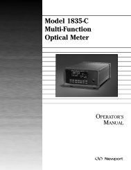
2832-C Dual-Channel<br />
Power Meter<br />
OPERATOR<br />
MANUAL
Model 2832-C<br />
Dual-Channel Power Meter
Warranty<br />
<strong>Newport</strong> <strong>Corporation</strong> warrants this product to be free from defects in material<br />
and workmanship for a period of 1 year from the date of shipment. If<br />
found to be defective during the warranty period, the product will either be<br />
repaired or replaced at <strong>Newport</strong>’s option.<br />
To exercise this warranty, write or call your local <strong>Newport</strong> representative, or<br />
contact <strong>Newport</strong> headquarters in Irvine, California. You will be given prompt<br />
assistance and return instructions. Send the instrument, transportation<br />
prepaid, to the indicated service facility. Repairs will be made and the instrument<br />
returned, transportation prepaid. Repaired products are warranted for<br />
the balance of the original warranty period, or at least 90 days.<br />
Limitation of Warranty<br />
This warranty does not apply to defects resulting from modification or misuse<br />
of any product or part. This warranty also does not apply to fuses, batteries,<br />
or damage from battery leakage.<br />
This warranty is in lieu of all other warranties, expressed or implied, including<br />
any implied warranty of merchantability or fitness for a particular use.<br />
<strong>Newport</strong> <strong>Corporation</strong> shall not be liable for any indirect, special, or consequential<br />
damages.<br />
Statement of Calibration<br />
This instrument has been inspected and tested in accordance with specifications<br />
published by <strong>Newport</strong> <strong>Corporation</strong>.<br />
The accuracy and calibration of this instrument and photodetector (where<br />
applicable) is traceable to the National Institute for Standards and Technology<br />
through equipment which is calibrated at planned intervals by comparison<br />
to the certified standards maintained at <strong>Newport</strong> <strong>Corporation</strong>.<br />
Copyright 1995, <strong>Newport</strong> <strong>Corporation</strong><br />
Part No. 21104-01, Rev. D<br />
IN-02951 (6-99)<br />
ii
EC DECLARATION OF CONFORMITY<br />
Model 1830-C 2832-C<br />
We declare that the accompanying product, identified with the<br />
" " mark, meets the intent of the Electromagnetic Compatability<br />
Directive, 89/336/EEC and Low Voltage Directive 73/23/EEC.<br />
Compliance was demonstrated to the following specifications:<br />
EN50081-1 EMISSIONS:<br />
Radiated and conducted emissions per EN55011, Group 1,<br />
Class A<br />
EN50082-1 IMMUNITY:<br />
Electrostatic Discharge per IEC 1000-4-2, severity level 3<br />
Radiated Emission Immunity per IEC 1000-4-3, severity level 2<br />
Fast Burst Transients per IEC 1000-4-4, severity level 3<br />
Surge Immunity per IEC 1000 4-5, severity level 3<br />
IEC SAFETY:<br />
Safety requirements for electrical equipment specified in<br />
IEC 1010-1.<br />
Alain Danielo<br />
Jeff Cannon<br />
VP European Operations<br />
General Manager-Precision Systems<br />
Zone Industrielle<br />
1791 Deere Avenue<br />
45340 Beaune-la-Rolande, France Irvine, Ca. USA<br />
iii
Table of Contents<br />
Warranty ................................................................................................................. ii<br />
EC Declaration of Conformity ............................................................................. iii<br />
List of Figures ....................................................................................................... vii<br />
List of Tables .......................................................................................................viii<br />
Safety Symbols and Terms .................................................................................. ix<br />
Definitions .............................................................................................................. x<br />
Specifications ........................................................................................................ xi<br />
Detector Signals and Calculations ................................................................... xiii<br />
Section 1 - General Information<br />
1.1 System Review ......................................................................................... 1<br />
1.2 Scope of This <strong>Manual</strong> .............................................................................. 2<br />
1.3 Unpacking and Inspection ...................................................................... 2<br />
1.4 Preparation for Use ................................................................................. 3<br />
1.5 Optional Accessories and Services ....................................................... 3<br />
Section 2 - System Operation<br />
2.1 Introduction ............................................................................................. 4<br />
2.2 Display....................................................................................................... 4<br />
2.3 Top Level Key Functions ........................................................................ 5<br />
O I<br />
2.3.1 , Power ................................................................................... 7<br />
2.3.2 (LOCAL)/SHIFT ............................................................................ 7<br />
2.3.3 DISP , Display Brightness ......................................................... 7<br />
2.3.4 FILTER, Signal Filtering ............................................................... 7<br />
2.3.5 ZERO, Offset Subtraction ........................................................... 8<br />
2.3.6 AUTO, Automatic Gain Ranging ................................................ 8<br />
2.3.7 CH A (B), Display Channel A (or B) .......................................... 8<br />
2.3.8 STO REF, Store Reference Value ............................................... 8<br />
2.3.9 REF SEL, Select Reference .......................................................... 9<br />
2.3.10 λ, Wavelength............................................................................... 9<br />
2.3.11 RANGE, Signal Range................................................................... 9<br />
2.3.12 R/S, Run-Stop.............................................................................. 10<br />
2.3.13 MODE, Measurement Mode ..................................................... 10<br />
2.3.14 UNITS, Display Units ................................................................. 10<br />
2.3.15 STATS, Moving Statistics .......................................................... 11<br />
2.3.16 R/S A (B), Run-Stop Channel A (or B) ..................................... 11<br />
2.3.17 EXT, External Trigger ................................................................ 11<br />
2.3.18 MENU ........................................................................................... 12<br />
2.3.19 ENTER ......................................................................................... 12<br />
2.3.20 ESC, Escape ................................................................................ 12<br />
2.3.21 , , , Adjust .................................................................. 12<br />
iv
2.4 Menu Level Functions ........................................................................... 13<br />
2.4.1 Menu Access and Movement ................................................... 13<br />
2.4.2 Data Store ................................................................................... 15<br />
2.4.3 Meter Configuration .................................................................. 16<br />
2.4.4 Auto Cal ...................................................................................... 17<br />
2.4.5 Attenuator .................................................................................. 18<br />
2.4.6 User Calibration ......................................................................... 18<br />
2.4.7 DC Sampling ............................................................................... 18<br />
2.4.8 Trigger Output ........................................................................... 19<br />
2.4.9 Trigger Input .............................................................................. 20<br />
2.4.10 Bar Graph ................................................................................... 20<br />
2.4.11 Remote Setup ............................................................................. 21<br />
2.4.12 General Information Functions ................................................ 21<br />
2.5 Connecting AC Power .................................................................................. 22<br />
2.6 Detector Connection and Setup ................................................................. 23<br />
2.7 Power Up ....................................................................................................... 24<br />
2.8 Performing Basic Measurements ............................................................... 24<br />
2.8.1 Making DC Power Measurements ........................................... 24<br />
Section 3 - Principles of Operation<br />
3.1 Introduction ........................................................................................... 25<br />
3.2 Analog Signal Flow ................................................................................. 25<br />
3.3 Digitized Signal Flow ............................................................................. 26<br />
3.4 Typical Detector Signals ....................................................................... 27<br />
3.5 Analog Output ........................................................................................ 27<br />
3.6 Measurement Considerations .............................................................. 28<br />
3.6.1 Detector Calibration and Accuracy ........................................ 28<br />
3.6.2 Quantum Detector Temperature Effects ................................ 28<br />
3.6.3 Ambient and Stray Light ........................................................... 29<br />
3.6.4 Common Measurement Errors ................................................ 29<br />
Section 4 - Computer Interfacing<br />
4.1 General Guidelines ................................................................................ 30<br />
4.2 Computer Interface Terminology ........................................................ 30<br />
4.3 Entering Remote Computer Interface Mode ...................................... 32<br />
4.4 RS-232C Communication ....................................................................... 32<br />
4.4.1 Setting Baud Rate and Echo Mode from the Keypad ........... 33<br />
4.4.2 Setting Baud Rate and Echo Mode from a Remote Interface33<br />
4.5 RS-232C XON/XOFF Handshaking Protocol........................................ 34<br />
4.6 GPIB Communication ............................................................................ 34<br />
4.6.1 Setting the GPIB Address ......................................................... 34<br />
Section 5 - Remote Command Reference<br />
5.1 Model 2832-C Remote Interface Commands ...................................... 35<br />
5.2 Device Independent Commands .......................................................... 38<br />
5.3 Device Dependent Commands ............................................................. 48<br />
v
Section 6 - Maintenance, Test and Troubleshooting<br />
6.1 Maintenance Procedures ...................................................................... 79<br />
6.2 Power Up Self Test ................................................................................ 79<br />
6.3 Troubleshooting Guide ......................................................................... 80<br />
Section 7 - Factory Service<br />
7.1 Introduction ........................................................................................... 82<br />
7.2 Obtaining Service .................................................................................. 82<br />
Service Form ................................................................................................... 83<br />
Appendices<br />
A Syntax and Definitions .......................................................................... 85<br />
B Error Messages ...................................................................................... 89<br />
C Status Reporting System ...................................................................... 92<br />
D Sample Programs ................................................................................... 97<br />
vi
List of Figures<br />
1. Model 2832-C Controller and Accessories .......................................... 1<br />
2a. Model 2832-C VFD Display ...................................................................... 4<br />
2b. Description of Model 2832-C Display Regions ..................................... 4<br />
3. Front Panel Key Pad ................................................................................ 6<br />
4. Decimal Point Indication of Menu Hierarchy Position ..................... 13<br />
5. Rear Panel Power Supply Voltage Switches in Positions L, R ......... 22<br />
6. Connecting a Detector with its Calibration Module ......................... 23<br />
7. Model 2832-C Detector Calibration Module Input Port .................... 23<br />
8. Model 2832-C Analog Signal Flow Diagram ........................................ 25<br />
9. Model 2832-C Digitized Signal Flow Block Diagram .......................... 26<br />
10. RS-232 Cable Connections .................................................................... 33<br />
vii
List of Tables<br />
Table 1. Model 2832-C Display Annunciators .......................................... 5<br />
Table 2. Model 2832-C Top Level Key Functions and Associated<br />
Remote Commands ...................................................................... 6<br />
Table 3. Model 2832-C Measurement Modes ......................................... 10<br />
Table 4. Valid Display Units Available to Detector Families by MODE 10<br />
Table 5. Displayed Unit Abbreviations vs. Actual Measurement Units . 11<br />
Table 6. Menu Level Key Functions and Parameters ........................... 14<br />
Table 7. Data Store Operations................................................................ 15<br />
Table 8. Configuration Parameters and Default Conditions ................ 16<br />
Table 9. Meter Configuration Operations .............................................. 17<br />
Table 10. User Calibration Operations ..................................................... 18<br />
Table 11. SAMPLE PREC States and Limits .............................................. 19<br />
Table 12. DC SAMPLING Operations ......................................................... 19<br />
Table 13. TRIGGER OUT Operations ......................................................... 20<br />
Table 14. EXT TRIGGER IN Operations ..................................................... 20<br />
Table 15. BARGRAPH Operations .............................................................. 21<br />
Table 16. REMOTE SETUP Operations...................................................... 21<br />
Table 17. GENERAL INFO Operations ....................................................... 21<br />
Table 18. Power Supply Voltage Switch Positions .................................. 22<br />
Table 19. Common Measurement Errors ................................................. 29<br />
Table 20. Model 2832-C IEEE-488.1 Capabilities Summary..................... 34<br />
Table 21. Device Independent Status Commands ................................... 35<br />
Table 22. Device Dependent Commands .................................................. 36<br />
Table 23. Symptom/Fault Troubleshooting Guide .................................. 80<br />
viii
Safety Symbols and Terms<br />
The following safety terms are used in this manual:<br />
The WARNING heading in this manual explains dangers that could result<br />
in personal injury or death.<br />
The CAUTION heading in this manual explains hazards that could damage<br />
the instrument.<br />
In addition, a NOTES heading gives information to the user that may be<br />
beneficial in the use of this instrument.<br />
GENERAL WARNINGS AND CAUTIONS<br />
The following general warnings and cautions are applicable to this<br />
instrument:<br />
WARNING<br />
This instrument is intended for use by qualified personnel who<br />
recognize shock hazards or laser hazards and are familiar with safety<br />
precautions required to avoid possible injury. Read the instruction<br />
manual thoroughly before using, to become familiar with the<br />
instrument’s operations and capabilities.<br />
WARNING<br />
The American National Safety Institute (ANSI) states that a shock<br />
hazard exists when probes or sensors are exposed to voltage levels<br />
greater then 42VDC or 42V peak AC. Do not exceed 42V between any<br />
portion of the Model 2832-C (or any attached detector or probe) and<br />
earth ground or a shock hazard will result.<br />
CAUTION<br />
There are no user serviceable parts inside the Model 2832-C. Work<br />
performed by persons not authorized by <strong>Newport</strong> may void the<br />
warranty. For instructions on obtaining warranty repair or service<br />
please refer to Section 5 of this manual.<br />
ix
Definitions<br />
A amps<br />
AC alternating current<br />
ADC analog-to-digital converter<br />
BAT battery option<br />
BIC biconic fiber connector<br />
BNC standard coaxial connector type<br />
C degrees Centigrade<br />
DC direct current<br />
F degrees Fahrenheit<br />
fA femtoamps<br />
Hz hertz (cycles per second)<br />
I-V current-to-voltage converter<br />
kHz kilohertz<br />
LSD least significant digit<br />
k kiloOhms<br />
mA milliamps<br />
mV millivolts<br />
nA nanoamps<br />
nF nanofarads<br />
nm nanometers<br />
pA picoamps<br />
RH relative humidity<br />
S/N serial number<br />
µA microamps<br />
µs microsecond<br />
V volts<br />
W watts<br />
x
Specifications<br />
Physical Specifications:<br />
4.2 x 8.8 x 13.9 in (107 x 224 x 353 mm)<br />
8 lb, 3 oz (3.7 kg)<br />
Metal case, painted<br />
(2) 8-Pin Sub Mini DIN CAL MODULE Inputs;<br />
(2) BNC Analog Outputs, Trigger Output and<br />
Trigger Input;<br />
9 Pin D-Sub RS-232, 24 Conductor GPIB<br />
100/120/220/240 VAC ±10%, 50/60 Hz<br />
5.5 digit annunciated VFD<br />
10 Hz<br />
Up to 7 decades (Detector and MODE depen-<br />
Dimensions:<br />
Weight:<br />
Enclosure:<br />
Connectors:<br />
Power:<br />
Display:<br />
Display Update Rate:<br />
Gain Ranges:<br />
dent)<br />
Operating Environment:<br />
Storage Environment:<br />
Compatible Detectors:<br />
0°C - 40°C; < 70% RH noncondensing<br />
-20°C - 60°C; < 90% RH noncondensing<br />
Low-Power (Semiconductor) Family<br />
xi
Electrical Specifications:<br />
DC Current Measurement (Low-Power, Semiconductor Photodiode CAL MODULE)<br />
Signal Range: 1,2 0 1 2 3 4 5 6<br />
Full-Scale Current: 4 2.51 nA 25.1 nA 251 nA 2.51 µA 25.1 µA 251 µA 2.50 mA<br />
A/D Resolution: 126 fA 1.26 pA 12.6 pA 126 pA 1.26 nA 12.6 nA 126 nA<br />
(20,000 Count Precision)<br />
Display Noise Floor: ≤ 8 LSD ≤ 1 LSD ≤ 1 LSD ≤ 1 LSD ≤ 1 LSD ≤ 1 LSD ≤ 1 LSD<br />
(Input Open, Filter Off)<br />
Full-Scale Accuracy: 3 ± 0.1% 0.05% 0.05% 0.05% 0.05% 0.05% 0.05%<br />
(Typical)<br />
Full-Scale Accuracy: 3 ±0.48% .30% .30% .30% .30% .30% .30%<br />
(Worst-Case)<br />
1<br />
Listed signal ranges specify meter capability. Available signal ranges are detector dependent.<br />
2<br />
Maximum measurable signal is detector dependent. See description of detector saturation message “SA”, page 80.<br />
3<br />
After 60 min warm-up, followed by execution of AUTOCAL command. See Section 2.4.4.<br />
4<br />
Full scale current may vary due to AUTOCAL compensation of DC offsets.<br />
Analog Output<br />
Full Scale Voltage: 0 - 2.5V into 50Ω<br />
Accuracy: ± 2.5%<br />
xii
Detector Signals and Calculations:<br />
S<br />
S d<br />
S – S d<br />
( S−<br />
Sd)<br />
R<br />
λ<br />
10 log ⎜<br />
⎝<br />
⎛ ( ) d<br />
( S−<br />
Sd)/ Rλ<br />
STO-REF<br />
S−<br />
S / R<br />
1mW<br />
⎛ ( )<br />
λ<br />
⎞<br />
⎟<br />
⎠<br />
S−<br />
S / R ⎞<br />
d λ<br />
10 log ⎜<br />
⎟<br />
⎝ STO-REF ⎠<br />
Represents the most recent signal value<br />
obtained from the A/D converter. It may<br />
represent amps or volts and may be analog<br />
and or digitally filtered.<br />
Represents the value stored as a reference<br />
signal for subsequent use in signal offset, i.e.<br />
ZERO calculations. S d<br />
=0 when ZERO is off.<br />
Represents the most recent net signal value.<br />
This is the value that is displayed when units<br />
are set to Amps or Volts. Note that Sd = 0<br />
when ZERO is off.<br />
Measurement calculation when the display<br />
units are Watts or Joules. R λ is the detector<br />
responsivity associated with the current<br />
wavelength setting.<br />
Measurement calculation when the display<br />
units are ten times the (base ten) logarithm of<br />
the ratio of the measured power to 1 mW, i.e.<br />
dBm.<br />
Measurement calculation when the display<br />
units are the ratio of measured power to the<br />
value stored by the STO-REF function.<br />
Measurement calculation when the display<br />
units are ten times the (base ten) logarithm of<br />
the ratio of measured power to the value<br />
stored by the STO-REF function.<br />
xiii
xiv
MODE:<br />
DC<br />
CONT<br />
DISP: CHA<br />
FILTER:<br />
ANLG + DIG<br />
EXT ZERO AUTO<br />
Section 1<br />
General Information<br />
1.1 System Review<br />
The Model 2832-C Dual-Channel Power Meter is a high performance instrument<br />
with a wealth of measurement and triggering features designed to<br />
provide measurement sensitivity, flexibility and speed. In spite of its power,<br />
Model 2832-C is also designed to provide simple operation with direct panel<br />
access to basic features and a shallow menu for access to advanced features.<br />
Great flexibility exists within the command structure of the Model 2832-C so<br />
that even complex measurements can be set up quickly and easily. The<br />
2832-C can react to or provide triggering or data log up to 1,000 measurements<br />
per channel!<br />
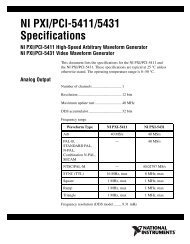
The Model 2832-C is compatible with <strong>Newport</strong>’s Low-Power detector family. A<br />
family tree of the 2832-C compatible detectors and accessories is shown in<br />
Figure 1 below.<br />
(SMA)<br />
(FC)<br />
(ST)<br />
818-FA<br />
FP3-CA3<br />
FP3-CA4<br />
FP3-CA6<br />
FP3-FH1<br />
(Bare Fiber<br />
Adaptor)<br />
818-FA2<br />
818-FA3-SMA<br />
818-FA3-ST<br />
818-FA3-FC<br />
818-UV/CM<br />
818-SL/CM<br />
818-IR/CM<br />
818-IG/CM<br />
818-ST/CM<br />
818-F-SL<br />
818-F-IR<br />
■ Dual Channel Power Meter<br />
■ Model 2832-C<br />
INPUT<br />
CH B<br />
CH A<br />
Figure 1 – Model 2832-C Controller and Accessories<br />
1
The Model 2832-C connects to detectors through a calibration module<br />
containing information unique to the detector being used. Calibration modules<br />
are ordered with a detector at the time of purchase and are labeled with<br />
the detector’s model number and serial number. Detectors with calibration<br />
modules have a “/CM” appended to their model number.<br />
EXAMPLE: 818-SL (no calib. module) 818-SL/CM (with calibration module)<br />
1.2 Scope of This <strong>Manual</strong><br />
Please carefully read this instruction manual before using the Model 2832-C<br />
Dual-Channel Power Meter. Be especially careful to observe the warnings and<br />
cautions throughout this manual. If any operating instructions are not clear,<br />
contact <strong>Newport</strong> <strong>Corporation</strong>. This instruction manual contains the necessary<br />
information for operation and maintenance of the <strong>Newport</strong> Model 2832-C Dual-<br />
Channel Power Meter as well as information for troubleshooting and obtaining<br />
service if necessary. This information is divided into the following sections:<br />
Section 1<br />
General Information and Functional Description<br />
Section 2<br />
System Operation<br />
Section 3<br />
Principles of Operation<br />
Section 4<br />
Computer Interfacing<br />
Section 5<br />
Remote Command Reference<br />
Section 6<br />
Maintenance, Test, and Troubleshooting<br />
Section 7<br />
Factory Service<br />
Appendix A<br />
Syntax and Definitions<br />
Appendix B<br />
Error Messages<br />
Appendix C<br />
Status Reporting System<br />
Appendix D<br />
Sample Programs<br />
1.3 Unpacking and Inspection<br />
All Model 2832-C Dual-Channel Power Meters are carefully assembled, tested<br />
and inspected before shipment. Upon receiving this instrument, check for<br />
any obvious signs of physical damage that might have occurred during<br />
shipment. Report any such damage to the shipping agent immediately.<br />
Retain the original packing materials in case reshipment becomes necessary.<br />
2
1.4 Preparation for Use<br />
The Model 2832-C Dual-Channel Power Meter should have some operations<br />
performed before measurements are made. These include:<br />
Connecting AC Power (Section 2.5)<br />
Detector Connection and Setup (Section 2.6)<br />
1.5 Optional Accessories and Services<br />
The <strong>Newport</strong> Catalog presents up-to-date information on detectors, detector<br />
accessories and detector calibration services available for use with the Model<br />
2832-C. Refer to Figure 1 for the Model 2832-C family tree of accessories.<br />
3
Section 2<br />
System Operation<br />
2.1 Introduction<br />
The Model 2832-C is designed to provide quick operation and to avoid a steep<br />
learning curve. This section starts by giving a brief listing of display, key pad<br />
and menu command features. Much of the Model 2832-C’s operation will be<br />
obvious after these descriptions. The manual then explains each key operation<br />
and menu command in detail. Reference each of these detailed explanations<br />
as required when getting started.<br />
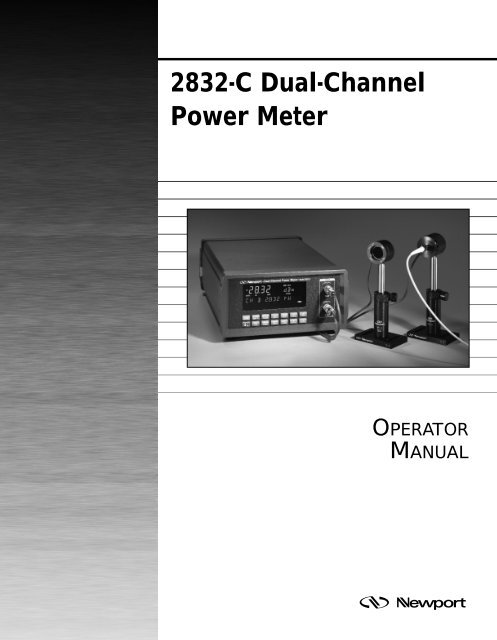
2.2 Display<br />
The Model 2832-C incorporates a vacuum fluorescent display, VFD, which can<br />
be clearly observed with most laser goggles and at high angles of incidence.<br />
Figure 2 illustrates and identifies the primary regions and annunciators<br />
within the Model 2832-C’s display.<br />
DISP: CHA CHB<br />
MODE: %<br />
DC<br />
SNGL<br />
CONT<br />
FILTER:<br />
ANLG + DIG<br />
SHIFT MENU EDIT STORE USR CAL EXT ATTN ZERO AUTO<br />
Figure 2a – Model 2832-C VFD Display<br />
Measurement<br />
Activity<br />
Annunciator<br />
Measurement<br />
Mode<br />
Annunciators<br />
MODE:<br />
Primary Channel<br />
Measurement Display Area<br />
= DC SNGL CONT<br />
DISP:<br />
FLTR:<br />
= CHA CHB<br />
Units Display<br />
= ANLG + DIG<br />
Secondary Channel, Bar Graph, Menu and Message Display Area<br />
SHIFT MENU EDIT STORE USRCAL EXT ATTN ZERO AUTO<br />
Display Channel<br />
Annunciators<br />
Signal Filtering<br />
Annunciators<br />
Status<br />
Annunciators<br />
Figure 2b – Description of Model 2832-C Display Regions<br />
4
Annunciator<br />
CH A<br />
CH B<br />
Table 1 – Model 2832-C Display Annunciators<br />
Comment<br />
The display is showing Channel A information in<br />
primary display area.<br />
The display is showing Channel B information in<br />
primary display area.<br />
Blinking indicates that the meter is making<br />
measurements.<br />
DC<br />
SNGL<br />
CONT<br />
ANLG<br />
DIG<br />
SHIFT<br />
MENU<br />
STORE<br />
USRCAL<br />
EXT<br />
AUTO<br />
ZERO<br />
ATTN<br />
Meter is set to make DC signal measurements.<br />
Meter will make only one measurement per front<br />
panel or external trigger.<br />
Meter will continuously make measurements until<br />
stopped.<br />
Analog signal filtering is on.<br />
Digital signal filtering is on.<br />
Indicates that the next key press will execute a blue<br />
key function.<br />
Meter and display are in menu mode. Measurement<br />
is stopped.<br />
Meter is logging measurements into memory, i.e.<br />
data logging.<br />
User (versus calibration module) has supplied the<br />
detector responsivity in use.<br />
External trigger input is enabled.<br />
Automatic signal gain ranging is on.<br />
Background signal subtraction (zeroing) is on.<br />
The responsivity in use includes the affect of the<br />
detector’s attenuator.<br />
2.3 Top Level Key Functions<br />
Operating controls for the Model 2832-C are found on both the front and rear<br />
panels of the Model 2832-C. For measurement operation, only the front panel<br />
controls are used. Rear panel controls are used for AC line power setup,<br />
Section 2.5. The front panel key pad of the Model 2832-C, Figure 3, provides<br />
quick access to measurement functions and menu access to advanced<br />
features and setup parameters. Most of the keys on the front panel only affect<br />
the channel indicated by the display channel annunciators. Table 2 and<br />
Sections 2.3.1 through 2.3.21 list and describe each top level key function.<br />
Menu level key functions are discussed in Section 2.4.<br />
5
(LOCAL)<br />
SHIFT<br />
STO REF<br />
DISP<br />
REF SEL<br />
FILTER<br />
λ<br />
ZERO<br />
RANGE<br />
AUTO<br />
CH A<br />
CH B<br />
O<br />
I<br />
EXT<br />
R/S<br />
MENU<br />
MODE<br />
ENTER<br />
UNITS<br />
ESC<br />
STATS<br />
R/S A<br />
R/S B<br />
Figure 3 – Front Panel Key Pad<br />
Table 2 – Top Level Key Functions and Associated Remote Commands<br />
Keypad Remote Commands Description<br />
O I<br />
None Turns the Model 2832-C on and off.<br />
(LOCAL)/ None If the meter is in the remote mode,<br />
SHIFT<br />
depressing this key puts the meter into<br />
the local mode. Also, this key enables the<br />
blue key functions.<br />
DISP DISP, DISP? Cycles display brightness:<br />
OFF,LOW,NORM and HIGH.<br />
FILTER FILTER_n, FILTER_n? Cycles signal filtering:<br />
OFF, ANLG, DIG and ANLG+DIG.<br />
ZERO ZERO_n, ZERO_n?, Zeroes the display via offset subtraction.<br />
STOZERO_n, ZEROVAL_n?<br />
AUTO AUTO_n, AUTO_n? Turns automatic gain ranging on and off.<br />
CH A DISPCH, DISPCH? Selects channel A as the primary display<br />
channel.<br />
CH B DISPCH, DISPCH? Selects channel B as the primary display<br />
channel.<br />
STO REF STOREF_n, STOREF_n? Stores last reading for future dB and<br />
REL measurements.<br />
REF SEL REFSEL_n, REFSEL_n? Selects the reference source to be used<br />
for dB and REL measurements.<br />
λ LAMBDA_n, LAMBDA_n? Displays and edits the calibration<br />
wavelength in use.<br />
RANGE RANGE_n, RANGE_n? Displays signal gain range in use.<br />
, None Adjusts gain range or parameter<br />
values or moves through a list.<br />
R/S RUN, STOP Toggles the signal acquisition of<br />
both channels.<br />
MODE MODE_n, MODE_n? Cycles meter between allowed<br />
measurement modes.<br />
UNITS UNITS_n, UNITS_n? Cycles display measurement units<br />
between those allowed.<br />
STATS<br />
STSIZE_n, STSIZE_n?, STMAX_n? Displays statistics.: Max, Min,<br />
STMIN_n?, STMXMN_n? Max-Min, Mean and Std. Dev.<br />
STMEAN_n, STSDEV_n?<br />
R/S A RUN_A, RUN_A? Starts and stops channel A signal<br />
acquisition.<br />
6
R/S B RUN_B, RUN_B? Starts and stops channel B signal<br />
acquisition.<br />
EXT EXT Enable or disable external triggering.<br />
MENU None Enter or exit MENU command mode.<br />
ENTER None Select next lower menu level or enter<br />
edit mode.<br />
ESC None Escape to next higher menu level or<br />
escape edit mode.<br />
, None Zooms bargraph in or out. When in<br />
Edit mode, selects the digit to be<br />
edited by the , keys.<br />
Note: n in a remote command stands for A (channel A) or B (channel B).<br />
2.3.1<br />
O<br />
I<br />
, Power<br />
The O I key toggles the Model 2832-C on and off. To turn the meter on, depress<br />
the O I key in until it clicks and stays in its depressed position. To turn the<br />
meter off, press the key again until it clicks and rebounds to its original length.<br />
2.3.2 (LOCAL)/SHIFT<br />
If the meter is in the remote mode, depressing this key the first time serves as a<br />
LOCAL key and puts the meter into the local mode. The remote mode is<br />
designated on the front panel by displaying an asterisk at the right-hand<br />
side of the secondary channel display area. If the meter is in the local-lockout<br />
mode,<br />
is displayed on the front panel.<br />
If the meter is not in the remote mode, pressing this key serves as a SHIFT.<br />
When SHIFT is pressed, the SHIFT display annunciator lights and the blue key<br />
functions (such as STOREF) are enabled. The next key press will cause that<br />
blue function to be executed and the “shift status” to disable.<br />
2.3.3 DISP , Display Brightness<br />
This key cycles the display and the backlit key pad through: OFF, LOW, NORM<br />
and HIGH brightness levels. This allows a user to operate in a dark environment<br />
without light pollution from the display, (except for one dim scanning<br />
decimal point and the measurement activity annunciator). When the display is<br />
OFF, the R/S, R/S A, or R/S B keys may be used to manually trigger measurements.<br />
Any other key press returns the display to the LOW brightness state<br />
while ignoring the key function.<br />
2.3.4 FILTER, Signal Filtering<br />
Press this key to cycle input signal filtering between: OFF, ANLG, DIG,<br />
ANLG+DIG. This function provides methods of lowering the noise observed in<br />
the measurement data and the analog output. When the ANLG annunciator is<br />
lit, a 5Hz low pass filter lowers the noise floor by attenuating high frequency<br />
signal components.<br />
7
When the DIG display annunciator is lit, measurements pass through a<br />
moving 10-sample averaging buffer before being further processed, stored or<br />
communicated to the display or computer interfaces. With DIG on, all observable<br />
values represent digitally averaged results relative to the original A/D<br />
conversions. This averaging is independent of the subsequent processing<br />
available through the STATS buffer, Section 2.3.15.<br />
2.3.5 ZERO, Offset Subtraction<br />
This key turns offset subtraction on and off. When turned on, the ZERO<br />
annunciator lights and the last signal reading is saved as S d<br />
and subtracted<br />
from all subsequent signal readings S. This causes subsequent signal calculations<br />
(and the display) to use the value S-S d<br />
instead of S.<br />
Offset subtraction allows one to remove the effects of ambient DC signals, by<br />
zeroing the display before making a measurement. Pressing the ZERO key a<br />
second time turns off the ZERO annunciator and stops offset subtraction.<br />
2.3.6 AUTO, Automatic Gain Ranging<br />
The AUTO key toggles automatic signal ranging on and off. When on, the<br />
AUTO annunciator lights and the signal range (amplifier gain) is adjusted to<br />
utilize maximum analog-to-digital converter resolution. When AUTO is turned<br />
off, the AUTO annunciator is turned off and the signal range is left in its<br />
current state.<br />
Signal range can be manually controlled by the , arrow keys. Pressing an<br />
, arrow key when AUTO is on (and STATS, MENU and λ are off), turns<br />
AUTO off and executes the manual range change. See RANGE, Section 2.3.11.<br />
Signal range changes will often not coincide with observable changes to the<br />
display value as the display is scaled by the detector responsivity and so must<br />
adjust independently. Signal range gains will occur in 1 decade steps when auto<br />
or manual ranging.<br />
AUTO gain ranging is not allowed in SNGL measurement modes. When exiting<br />
a SNGL measurement MODE, AUTO will turn back on if it was on when the<br />
SNGL measurement mode was entered. (See MODE, Section 2.3.13)<br />
2.3.7 CH A (B), Display Channel A (or B)<br />
The 2832-C has a primary channel and secondary channel display area. The<br />
primary channel is displayed in larger, bold characters, with the secondary<br />
channel displayed underneath it in slightly smaller characters.<br />
Depressing the CH A key causes channel A to be the primary display channel.<br />
The CH B key causes channel B to be the primary display channel. The<br />
display channel annunciators will indicate which channel is currently the<br />
primary display channel. When a display channel is selected, the front panel<br />
will change to reflect its settings and measurement data. Operations from the<br />
keypad or menu that affect a specific channel will only affect the currently<br />
displayed primary channel and not the other.<br />
2.3.8 STO REF, Store Reference Value<br />
STO REF causes the last measurement, D, to be stored as D ref<br />
for subsequent<br />
use in relative measurement calculations. When units are relative, REL, and<br />
the stored reference is selected, the displayed value is the ratio D/D ref<br />
. When<br />
units are logarithmic relative, dB, and the stored reference is selected the<br />
8
displayed value is the function 10 log (D/D ref<br />
). D ref<br />
is always a power reading<br />
stored in the units of Watts. Press STO REF to cause a new D ref<br />
to overwrite<br />
the existing D ref<br />
value.<br />
NOTE<br />
When not using remote interface operation and when displaying relative dB<br />
or REL measurements with the stored reference selected, the message<br />
display area will show the STO REF value used in the calculation.<br />
2.3.9 REF SEL, Select Reference<br />
The REF SEL key is used to select the reference value, Dref, to be used for<br />
relative, REL, and logarithmic relative, dB, unit readings. Press the REF SEL<br />
key to display the reference source in the message display area. The EDIT<br />
annunciator will be lit and the current selection will blink. Press , to<br />
select a new reference source. The choices will be:<br />
STO REF - The last stored measurement<br />
USR REF - User defined reference (see the USRREF command in Section 5.3<br />
Device Dependent Commands)<br />
CH A(B) - The other channel<br />
Press ENTER to accept the new reference source and exit the select reference<br />
mode. Press REF SEL or ESC to exit without changing the reference source.<br />
NOTE<br />
The CH A(B) source is only applicable if the other channel is available. If the<br />
other channel is not available then N/A will appear next to CH A(B) and you<br />
will not be able to select it.<br />
2.3.10 λ, Wavelength<br />
A detector calibration module contains responsivity data for its assigned<br />
detector at discrete wavelengths. By telling the meter which wavelength is<br />
being measured, the correct responsivity value is used in calculating the<br />
measured power or energy. When a wavelength falls between two calibration<br />
points, linear interpolation is used to approximate the true responsivity value.<br />
Press the λ key to display the measurement wavelength in the message<br />
display area. Press ENTER to light the EDIT annunciator and cause the last<br />
digit of the wavelength to blink. Press , to adjust the blinking digit up or<br />
down and , to change which digit blinks. Press the ENTER a second time<br />
to accept the new wavelength and exit the wavelength edit/display mode.<br />
Press λ or ESC to exit without changing the wavelength.<br />
2.3.11 RANGE, Signal Range<br />
RANGE key allows the user to view the amplifier signal range. Signal ranges<br />
step in 1 decade gain increments in order to utilize maximum resolution from<br />
the meter’s analog-to-digital converters. The available signal ranges are<br />
detector dependent. Press RANGE to display the signal range number in the<br />
message display area. If AUTO is on, then the signal range number will<br />
change if the detector signal varies more than a decade in magnitude. Signal<br />
range changes can occur without an effect on the displayed measurement<br />
value. Press RANGE a second time to exit the signal range display mode.<br />
9
Press the , arrow keys to increase or decrease the signal range. If AUTO<br />
is on, pressing the , arrow keys will disable AUTO and cause the signal<br />
range to change. <strong>Manual</strong> ranging is useful when working with external analog<br />
recording equipment.<br />
NOTE<br />
Pressing the , arrow keys will disable AUTO ranging and change the signal<br />
range even when the signal range is not being displayed via the RANGE key.<br />
2.3.12 R/S, Run-Stop<br />
The R/S run-stop key provides front panel control over data acquisition for<br />
both channels simultaneously. If the channel is in SNGL measurement mode,<br />
each<br />
R/S key press causes one reading to be taken. In CONT measurement mode,<br />
each R/S key press toggles continuous data acquisition on and off.<br />
The activity annunciator (Figure 2b) flashes to indicate that readings are<br />
being taken on the displayed channel as indicated in the upper right hand<br />
corner of the display. The indicator is off when data acquisition on the<br />
displayed channel has been stopped. In the special case that both channels<br />
are started together in DC CONT mode the readings will be synchronized<br />
together with channel A readings leading channel B readings by about 70 µsec.<br />
Otherwise the channels run independent of each other.<br />
2.3.13 MODE, Measurement Mode<br />
The Model 2832-C acquires data in either continuous or in a single-step mode.<br />
Press the MODE key until the desired mode is indicated in the mode annunciator<br />
area of the display. Table 3 gives a description of the two modes available<br />
on the 2832-C.<br />
Mode<br />
DC CONT<br />
DC SNGL<br />
Table 3 – Model 2832-C Measurement Modes<br />
Description<br />
Measurement occurs at a programmable sample rate,<br />
Section 2.4.7.<br />
A measurement is taken every time the meter receives a<br />
trigger up to a 500Hz rate when two detector calibration<br />
modules are plugged into the meter and 1000Hz for one.<br />
(AUTO is disabled in SNGL mode.)<br />
2.3.14 UNITS, Display Units<br />
Measurements can be displayed in various units. The set of available units is<br />
described in Table 4. Press the UNITS key to cycle the display through the set<br />
of available units.<br />
Table 4 – Valid Display Units Available to Low Power Detectors by MODE.<br />
MODE A W W/cm 2 dBm dB REL<br />
DC CONT <br />
DC SNGL <br />
10
denotes the default units for the detector in the given measurement mode.<br />
Some display units are abbreviated. Table 5 lists displayed units versus<br />
actual measurement units. Display units are limited to four characters in<br />
order to provide for display engineering prefixes such as: p, n, µ, m and k<br />
(pico, nano, micro, milli and kilo respectively).<br />
Table 5 – Displayed Unit Abbreviations Versus Actual Measurement Units.<br />
Actual Units A W W/cm 2 dBm dB REL<br />
Displayed Units A W W/cm dBm dB E±dd<br />
2.3.15 STATS, Moving Statistics<br />
The STATS key causes a list of statistical results from the stats buffer of the<br />
display channel to be displayed in the message display area. The stats buffer<br />
is a moving data window containing the most recent measurements to a<br />
depth 1 ≤ N ≤ 100. The default value is N = 10. Display occurs without<br />
disrupting data acquisition or storage and results are continuously updated.<br />
Press the STATS key to enter the stats display list. The first statistic displayed<br />
will be the stats buffer depth N. Press the , adjust keys to move<br />
through the list. The following statistics are available: N, MAX, MIN, MAX-<br />
MIN, MEAN and STD DEV.<br />
When the STATS buffer depth, N, is displayed, it can be adjusted by pressing<br />
ENTER and using the , keys to set a new value for N. Press the ENTER<br />
key to adopt the new value for N and escape the edit mode. The STATS buffer<br />
is cleared whenever a new stats buffer depth N, or MODE or UNITS is established.<br />
Press the STATS key a second time to exit the stats display mode.<br />
2.3.16 R/S A(B), Run-Stop Channel A (or B)<br />
The R/S A and R/S B run-stop keys provides front panel control over data<br />
acquisition for each individual channel. When in SNGL measurement mode,<br />
each R/S A(B) key press causes one reading to be taken on the respective<br />
channel. In CONT measurement mode, each R/S A(B) key press toggles<br />
continuous data acquisition on and off on the respective channel.<br />
The activity annunciator (Figure 2b) flashes to indicate that readings are<br />
being taken on the display channel as indicated in the upper righthand corner<br />
of the display. The indicator is off when data acquisition on the displayed<br />
channel has been stopped.<br />
2.3.17 EXT, External Trigger<br />
EXT enables and disables the triggering of data acquisition through the rear<br />
panel trigger input BNC connector. The meter can be configured to be<br />
triggered by either a rising or falling edge TTL signal. See Section 2.4.9.<br />
Press EXT to light the EXT annunciator and enable the external trigger input to<br />
both channels. The Model 2832-C will still respond to triggers from the R/S, R/S<br />
A, or R/S B keys even when the EXT trigger is enabled. Press the EXT key a<br />
second time to turn off the annunciator and disable the external trigger input.<br />
11
2.3.18 MENU<br />
The MENU key provides access to advanced features and parameters. Press<br />
the MENU key to stop all data acquisition, light the MENU annunciator, and<br />
display the first item of the top level menu list. Press the MENU key a second<br />
time to immediately exit the menu. Menu structure and functions are presented<br />
in Section 2.4. The menu consists of a series of lists and parameter<br />
values. Most parameter values can be edited to configure the meter. Lists are<br />
moved through via the , keys. To move to a lower level list, press the<br />
ENTER key. To escape a lower level list, press the ESC key.<br />
In the menu, all key functions are ignored except for the MENU, ENTER, ESC<br />
and the , keys. Each key will act without having to initially press SHIFT.<br />
Pressing SHIFT will toggle the SHIFT annunciator, but it will not effect anything<br />
else when in MENU mode.<br />
To edit a displayed parameter press ENTER. This enables the edit mode and<br />
causes the parameter (or a digit) to blink. Press the , keys to adjust the<br />
parameter through its allowed list or to count the blinking digit up and down.<br />
When adjusting a numerical value, the , keys can be used to change<br />
which decimal digit blinks. Press ENTER to adopt the new value and escape<br />
the editing mode. Press ESC to leave the editing mode without adopting the<br />
new value.<br />
2.3.19 ENTER<br />
ENTER allows one to move lower into the menu when in menu mode, to enter<br />
editing mode when an editable parameter is being displayed and to adopt a<br />
new parameter value after it has been edited. Editable parameters can be<br />
found both in and out of the menu mode. If ENTER is pressed when a noneditable<br />
parameter is being displayed, the key press is ignored.<br />
2.3.20 ESC, Escape<br />
ESC allows one to escape to the next higher level when in menu mode and to<br />
escape editing mode when editing a parameter value without adopting any<br />
changes to the parameter. At the top level of the menu, pressing the ESC key<br />
exits the menu mode. The ESC key also allows one to escape various other<br />
display modes such as STATS or wavelength display or amplifier signal gain<br />
range display modes. When there is nothing to escape from, the ESC key is<br />
ignored.<br />
2.3.21 , , , Adjust<br />
The , , , keys allow one to adjust various parameter states and values.<br />
In normal operation, the , keys turn AUTO off and adjust the amplifier<br />
signal gain. In any other mode, the , keys cause one to move through a list<br />
or to adjust a blinking digit. The , keys zoom the bargraph ( in, out)<br />
and in edit mode, select which digit of a numerical value will blink.<br />
12
2.4 Menu Level Functions<br />
Menu functions provide control over parameter values and methods of<br />
making measurements. The menu consists of a number of lists and parameter<br />
values. Table 6 presents a quick summary of the hierarchy of the menu<br />
functions and parameters. Most settings displayed in the menu and changes<br />
to those settings affect the channel indicated by the display channel annunciator.<br />
2.4.1 Menu Access and Movement<br />
To access the menu press MENU. The MENU annunciator will light and data<br />
acquisition will stop. Menu labels and parameter values are displayed in the<br />
message display area. The first, second and third leftmost decimal points<br />
within this area indicate a current position at the top, second, third or fourth<br />
level of the menu hierarchy, Figure 4. Table 6 presents the menu functions<br />
and their hierarchy.<br />
Top Level<br />
Second Level<br />
Third Level<br />
Fourth Level<br />
Figure 4 – Decimal Point Indication of Menu Hierarchy Position<br />
In the menu, valid keys are limited to those needed to perform operations to<br />
move through the menu or edit a parameter value. In the menu, it is not<br />
necessary to hit the SHIFT key to invoke the action of the menu keys: MENU,<br />
ENTER, ESC or , , , . The SHIFT key will toggle the SHIFT annunciator,<br />
but with no effect on subsequent pressings of other keys. Once in the menu,<br />
the rules for moving through the menu are as follows:<br />
i. Press ENTER to move to the next level down or to enter the edit mode if a<br />
editable parameter is being displayed and to accept a parameter value in<br />
its currently displayed state and exit edit mode.<br />
ii. Press ESC to move to the next level up or to escape the menu when at the<br />
top level or to exit edit mode without changing the parameter value being<br />
edited.<br />
iii. Press MENU to immediately escape the menu regardless of current level<br />
within the menu.<br />
iv. Use the , keys to move up or down through a menu list on a given<br />
level. Also use these keys to adjust a parameter or decimal value when in<br />
edit mode.<br />
v. Use the , keys to select the digit being adjusted when in edit mode.<br />
13
Table 6 – Menu Level Key Functions and Parameters<br />
Top Level Second Level Third Level<br />
DATA STORE DATA STORE OFF DATA STORE ON, OFF<br />
CLR DATA BUFFER<br />
(or DATA BUFFER CLR)<br />
SLIDE BUFFER SLIDE, FIX BUFFER<br />
D_BUF SIZE dddd D_BUF_SIZE dddd<br />
VIEW DATA dddd OF dddd<br />
SAVE CONFIG SAVE TO d<br />
RECALL CONFIG RCL DEFAULT, d<br />
AUTO CAL<br />
ATTENUATOR ATTN ON, OFF<br />
USER CALIB USR CAL OFF USR CAL ON, OFF<br />
USR RESP d.dddE±d A/W<br />
PRESENT RESP d.dddE±d A/W<br />
DC SAMPLING SAMPLE PREC PREC= 20000, 4096<br />
CNT<br />
SAMPLE FREQ FREQ = ddd.ddd HZ<br />
TRIGGER OUT TRIG ON CMPLT TRIG ON CMPLT,<br />
TRIG AT FREQ ,<br />
TRIG ON LEVEL,<br />
TRIG OUT OFF<br />
TRIG POLARITY TRIG ACTIVE LO, HI<br />
TRIGGER FREQ FREQ= dddd.ddd HZ<br />
TRIGGER LEVEL LVL= ±d.ddd E±dd W<br />
EXT TRIGGER IN FALLING , RISING EDGE<br />
BAR GRAPH OFF BAR GRAPH ON, OFF<br />
REMOTE SETUP GPIB ADDR dd GPIB ADDR dd<br />
BAUD RATE 9600 BAUD RATE 1200,<br />
2400, 4800, 9600, 19.2K<br />
RS-232 ECHO OFF RS-232 ECHO ON, OFF<br />
GENERAL INFO MODEL 2832-C<br />
SW VERSION d.d<br />
DETECTOR INFO MODEL xxxxxx<br />
DET SN ddddd<br />
ATTN SN ddddd<br />
CAL ddMONyyyy<br />
Items in bold italics type are editable states or decimal values. Decimals are<br />
denoted by d. Move vertically via the , keys. Move horizontally via<br />
ENTER and ESC.<br />
14
2.4.2 Data Store<br />
The Model 2832-C allows a user to save up to 1000 measurements for each<br />
channel for a total of 2000 measurements. These measurements are stored in<br />
an internal buffer for subsequent viewing or transmission over a computer<br />
interface. A separate buffer is maintained and configured for each channel.<br />
Data is maintained on power down, but lost when a new configuration is<br />
loaded, Section 2.4.3, or when the buffer is cleared via the CLR DATA BUFFER<br />
command or when data with new units is being stored.<br />
The data store buffer operates in two ways: SLIDE or FIX. In SLIDE configuration,<br />
the buffer slides along storing the most recent measurements up to the<br />
size of the buffer. Beyond this, as data enters the buffer, the oldest data is<br />
pushed out and lost. In FIX configuration, data storing continues until the<br />
data buffer is full. After this, data acquisition stops and no additional data can<br />
be stored without first clearing the buffer via the CLR DATA BUFFER command.<br />
DATA BUFFER CLR is displayed when the buffer is empty.<br />
The size of the buffer is set by the D_BUF_SIZE dddd menu function. Edit the<br />
value dddd to establish the number of data points that the buffer will hold<br />
before dropping old data or stopping data storage.<br />
Data storing is enabled by the user via the DATA STORE menu function. Edit<br />
the ON, OFF condition to enable or disable data storing and the associated<br />
STORE annunciator.<br />
When in CONT mode, data acquisition and storage is resumed immediately<br />
upon exiting the menus if acquisition is active as the menu is entered. When<br />
acquisition is not active when the menu is entered, or when in SNGL mode,<br />
data acquisition and storage requires an initiating R/S key press, external<br />
trigger or a remote RUN command upon exiting the menu.<br />
Buffer data can be viewed via the VIEW DATA menu command. Data are<br />
displayed in the measurement area while the message area displays the<br />
position within the buffer: dddd of dddd. Use the , keys to move through<br />
the buffer data. The value dddd = 0001 is the first, i.e. the oldest datum.<br />
NOTE<br />
When DATA STORE is off, CONT acquisition mode behavior defaults to the<br />
condition where data acquisition is begun without the requirement of a<br />
starting trigger. SNGL acquisition modes always require a trigger for each<br />
acquisition.<br />
Table 7 – Data Store Operations<br />
Menu Operation Keypad Commands Associated Remote Commands<br />
DATA STORE ON, OFF Edit ON, OFF status. DSE_n, DSE_n?<br />
DATA BUFFER CLR or<br />
CLR DATA BUFFER If CLR DATA BUFFER, DSCLR_n<br />
press ENTER to clear buffer<br />
SLIDE, FIX BUFFER Edit SLIDE, FIX BUFFER DSBUF_n, DSBUF_n?<br />
D_BUF_SIZE dddd Edit D_BUF_SIZE dddd DSSZ_n, DSSZ_n?<br />
VIEW DATA Press ENTER and use DS_n?, DSCNT_n?, DSUNITS_n?<br />
, keys.<br />
NOTE<br />
n in a remote command stands for A (channel A) or B (channel B).<br />
15
2.4.3 Meter Configuration<br />
The Model 2832-C provides a method to save the configuration of the entire<br />
meter and to recall that configuration for later use even if the meter has been<br />
turned off. This is accomplished through configuration buffers maintained in<br />
nonvolatile memory. Configuration buffers are numbered 0 to 9 with buffer 0<br />
being a DEFAULT buffer which can only be recalled but not saved to. The<br />
reset state of all the buffers except the default buffer is empty. Empty buffers<br />
cannot be recalled.<br />
A recalled configuration becomes the current configuration of the meter. Any<br />
changes to the current configuration must be saved via SAVE CONFIG or they<br />
will be lost when a new configuration is recalled.<br />
The meter will not recall a configuration that is not compatible with either<br />
detector calibration module currently plugged into the meter. Configurations<br />
using the same model of detector are compatible while configurations using<br />
different models of detectors are incompatible. The list of configuration<br />
parameters stored in a configuration buffer as well as their default values are<br />
listed in Table 8 below:<br />
Table 8 – Configuration Parameters and Default Conditions<br />
Parameter<br />
Default Condition<br />
MODE<br />
DC CONT<br />
UNITS<br />
W<br />
λ, Lambda Lowest available<br />
PRESENT RESP<br />
PRESENT RESP<br />
USR CAL<br />
OFF<br />
ATTN<br />
OFF<br />
FILTER<br />
OFF<br />
DC SAMPLE PREC<br />
20,000 CNT<br />
DC SAMPLE FREQ<br />
25 Hz<br />
AUTO<br />
ON<br />
RANGE<br />
Lowest available<br />
ZERO<br />
OFF<br />
Zero Value 0.000<br />
REF SEL<br />
STO REF<br />
Reference Value 0.001<br />
STATS Buffer Size 10<br />
DATA STORE<br />
OFF<br />
DATA STORE BUFFER<br />
SLIDE<br />
16
Parameter<br />
Default Condition<br />
D_BUF_SIZE 100<br />
Data Store Units<br />
Same as UNITS<br />
EXT<br />
OFF<br />
EXT TRIG IN<br />
FALLING<br />
TRIGGER OUT<br />
TRIG ON CMPLT<br />
TRIG OUT POL<br />
TRIG ACTIVE LO<br />
TRIG OUT FREQ<br />
FREQ = 30 Hz<br />
TRIG LEVEL<br />
LVL = 0.001 W<br />
BAR GRAPH<br />
OFF<br />
GPIB ADDR 05<br />
BAUD RATE 9600<br />
These parameters adopt the following default values at power up and are not<br />
affected by recalling a configuration or by setting the configuration to default.<br />
RS-232 ECHO<br />
OFF<br />
Local Lockout<br />
OFF<br />
Display Brightness<br />
NORMAL<br />
Table 9. below lists the menu commands effecting the saving and recalling of<br />
meter configurations.<br />
Table 9 – Meter Configuration Operations<br />
Menu Operation Keypad Commands Associated Remote Commands<br />
SAVE CONFIG Adjust SAVE TO d, *SAV<br />
and ENTER<br />
RECALL CONFIG Adjust RECALL d, *RCL,*RST<br />
and ENTER<br />
2.4.4 AUTO CAL<br />
The AUTO CAL command causes the 2832-C to perform A/D conversions of<br />
amplifier offset voltages (zero errors) arising from aging and temperature<br />
effects. These conversions are then used in subtracting the appropriate error<br />
voltage from each reading during normal operation. The 2832-C automatically<br />
performs this procedure every time it powers up (or is reset). To achieve<br />
stable reading at the specified accuracy, AUTO CAL should be executed for<br />
each channel after a minimum 60 minute warm-up period from power-up.<br />
Simply press ENTER when AUTO CAL is displayed. The display message area<br />
will display “ONE MOMENT”, followed by a buzzer sound indicating that<br />
AUTO CAL is complete. Low Power detectors do not have to be connected to<br />
the 2832-C or removed from the radiation source to effectively execute AUTO<br />
CAL.<br />
17
2.4.5 Attenuator<br />
The Attenuator selects the responsivity value, R λ<br />
, to be the value for the<br />
detector alone or the value for the detector-with-attenuator. When ATTN is<br />
ON the ATTN annunciator is lit and the responsivity of the detector-withattenuator<br />
is used. When ATTN is OFF, the annunciator is off and the detector-alone<br />
responsivity is used. If the detector does not have an attentuator, or<br />
if USR CAL is on (Section 2.4.6) the ATTN setting has no effect.<br />
2.4.6 User Calibration<br />
The Model 2832-C allows one to create a detector responsivity which overrides<br />
the responsivities obtained from the detector’s calibration module.<br />
This allows one to account for the effects of additional optics and filters in the<br />
measurement path. When USR CAL is on, the USR CAL annunciator is lit and<br />
the meter adopts the responsivity value displayed by the editable USR RESP<br />
value. Use the PRESENT RESP function to display the current calibration<br />
module responsivity.<br />
The USR RESP units are the same as the PRESENT RESP units. Table 10 lists<br />
the possible user calibration operations.<br />
Table 10 – User Calibration Operations<br />
Menu Operation Keypad Commands Associated Remote Commands<br />
USR CALIB ON, OFF Edit USR CALIB USRCAL_n, USRCAL_n?<br />
ON, OFF<br />
USR RESP<br />
Edit d.dddE±dd A/W* USRRESP_n, USERRESP_n?<br />
PRESENT RESP ENTER to view RESP_n?<br />
d.dddE±dd A/W*<br />
*These units are not editable.<br />
NOTE<br />
n in a remote command stands for A (channel A) or B (channel B).<br />
2.4.7 DC Sampling<br />
The Model 2832-C incorporates two analog-to-digital, (A/D) converters, one<br />
with 20,000 count resolution and a second with 4096 count resolution. The<br />
user may select which A/D will be used for both channels during DC CONT<br />
and DC SNGL acquisition modes. All other modes use the 4096 count A/D.<br />
The 20,000 count A/D converter can operate at sample rates up to 25 Hz.<br />
When two detector calibration modules are plugged into the meter, the 4,096<br />
count A/D converter can operate at sample rates up to 500 Hz. When one<br />
detector calibration module is plugged into the meter, the 4,096 count A/D<br />
converter can operate at sample rates up to 1000 Hz.<br />
The SAMPLE PREC menu command, Table 11, selects which analog-to-digital<br />
converter is used for both channels. The sampling frequency for both<br />
channels can be adjusted within the limits imposed by the SAMPLE PREC<br />
state, see Table 12. When the SAMPLE PREC state changes, the sampling<br />
frequency defaults to 25 Hz if the existing SAMPLE FREQ is incompatible with<br />
the new SAMPLE PREC state. The SAMPLE FREQ and the SAMPLE PREC<br />
settings affect both channels, not just the display channel.<br />
18
Table 11 – SAMPLE PREC States and Limits.<br />
SAMPLE PREC A/D Accuracy Sample Frequency Range<br />
20000 CNT 20,000 counts 0.001 Hz to 25.0 Hz<br />
4096 CNT 4,096 counts 0.001 Hz to 500.0 Hz or 1000.0 Hz<br />
Table 12 – DC SAMPLING Operations.<br />
Menu Function Keypad Commands Associated Remote Commands<br />
SAMPLE PREC Edit PREC= 20,000, SPREC, SPREC?<br />
4096 CNT<br />
SAMPLE FREQ Edit FREQ= SFREQ, SFREQ?<br />
ddd.ddd HZ<br />
2.4.8 Trigger Output<br />
The Model 2832-C’s rear panel TTL trigger output allows it to coordinate<br />
activities among other instruments. The trigger output can operate in several<br />
ways: conversion complete, periodic output and comparator output. In<br />
addition, the polarity of the trigger output can be specified.<br />
CAUTION<br />
Precautions should be taken whenever the trigger output is used to<br />
coordinate activities among instruments. Static discharges at or near the<br />
meter may cause false triggering, causing the trigger output to go active.<br />
In TRIG ON CMPLT mode, a pulse is output after each reading has been<br />
acquired and completely processed from either channel. When acquiring on<br />
one channel, it indicates that the 2832-C is ready to take another reading. The<br />
width of this pulse is at least 8 µS.<br />
In TRIG AT FREQ mode, a pulse is output at a user defined frequency or rate.<br />
Each pulse width is at least 8 µS and the programmable frequency range of<br />
the pulses is 0.001 Hz to 1000.0 Hz.<br />
In TRIG ON LEVEL mode, each measurement is compared to a programmable<br />
trigger level. The units of the trigger level always equal Watts for power<br />
detectors. If a measurement is less than the specified value, then the trigger<br />
output is inactive. If the measurement exceeds the specified value then the<br />
trigger output becomes active. The TRIG ON LEVEL output is a shift in level<br />
rather than a pulse.<br />
If both channels are sampling when this function is initiated, the time lag<br />
between subsequent triggers is less than 700 µsec. If a R/S A or R/S B is<br />
initiated twice, then the separation between TTL OUTPUTS is relative to the<br />
RUN command initialization, giving a time lag up to one sample period<br />
between channel triggers (depending on sample frequency chosen).<br />
The polarity of the trigger output is programmable as active high or active<br />
low. If the polarity is active high then the output will idle low. If the polarity<br />
is active low then the line will idle high.<br />
19
Table 13 – TRIGGER OUT Operations.<br />
Menu Function Keypad Commands Associated Remote Commands<br />
TRIGGER OUT Edit TRIG ON CMPLT TRIGOUT, TRIGOUT?<br />
TRIG AT FREQ<br />
TRIG ON LEVEL<br />
TRIG OUT OFF<br />
TRIG POLARITY Edit ACTIVE HI, LO TRIGOUTPOL, TRIGOUTPOL?<br />
TRIGGER FREQ Edit FREQ= ddd.ddd Hz TRIGOUTFREQ, TRIGOUTFREQ?<br />
TRIGGER LEVEL Edit LVL= d.dddE±dd W TRIGOUTLVL, TRIGOUTLVL?<br />
2.4.9 Trigger Input<br />
The Model 2832-C’s rear panel TTL external trigger input can be enabled or<br />
disabled, Section 2.3.17, and have its edge polarity set. The edge polarity is<br />
accessed via the EXT TRIGGER IN menu function and can be set to rising or<br />
falling edge triggering.<br />
The external trigger affects both channels and, like the R/S key, acts like an<br />
acquisition trigger when in SNGL modes and acts like a toggled acquisition gate<br />
when in CONT modes.<br />
The external trigger pulse width must be ≥200 ns. In DC SNGL mode, the<br />
delay from the trigger input going active to the start of the A/D conversion is<br />
Table 15 – BARGRAPH Operations.<br />
Menu Function Keypad Commands Associated Remote Commands<br />
BAR GRAPH Edit BARGRAPH BARGRAPH, BARGRAPH?<br />
ON, OFF<br />
2.4.11 Remote Setup<br />
The Model 2832-C provides both RS-232 and IEEE-488 computer interfaces as<br />
standard features. Each interface requires that certain parameters be set.<br />
Remote interface setup and commands are discussed in Section 4, Computer<br />
Interfacing.<br />
Table 16 – REMOTE SETUP Operations.<br />
Menu Function Keypad Commands Associated Remote Commands<br />
GPIB ADDR dd Edit GPIB ADDR dd None<br />
BAUD RATE dddd Edit BAUD RATE 1200, None<br />
2400, 4800, 9600, 19.2K<br />
RS-232 ECHO Edit RS-232 ECHO ECHO, ECHO?<br />
ON, OFF<br />
ON, OFF<br />
2.4.12 General Information Functions<br />
General information about the Model 2832-C and any attached detector can be<br />
found using the GENERAL INFO menu functions. These functions display the<br />
Model 2832-C software version, the detector’s model number, serial number,<br />
associated attenuator serial number and calibration date.<br />
Table 17 – GENERAL INFO Operations.<br />
Menu Function Keypad Commands Associated Remote Commands<br />
MODEL cccccccc For viewing only. DETMODEL?<br />
SW VERSION d.d For viewing only. *IDN?<br />
DET SN ddddd For viewing only. DETSN?<br />
ATTN SN ddddd For viewing only. ATTNSN?<br />
CAL ddMonyyyy For viewing only. CALDATE?<br />
21
2.5 Connecting AC Power<br />
Model 2832-C can be configured to operate with line voltages of 100/120/220/<br />
240 VAC, 50-60 Hz. Before turning the meter on, configure it to local voltage<br />
using the following procedure:<br />
i. Configure the Model 2832-C’s power supply voltage selection switches to<br />
match the nominal local voltage. See Figure 5 and Table 18.<br />
ii. Plug an AC line power cord to the rear of the Model 2832-C and then<br />
connect the cord to AC power.<br />
50–60 Hz<br />
100 V<br />
120 V<br />
LINE<br />
SWITCH 1 SWITCH 2<br />
SELECT<br />
240 V<br />
220 V<br />
Figure 5 – Rear Panel Power Supply Voltage Switches in Positions with<br />
Switch 1 set to Left and Switch 2 set to Right<br />
Table 18 – Power Supply Voltage Switch Positions.<br />
Switch 1 Position Switch 2 Position Nominal Local Voltage<br />
Right Right 100 VAC<br />
Right Left 120 VAC<br />
Left Right 220 VAC<br />
Left Left 240 VAC<br />
WARNING<br />
This product is equipped with a 3 wire grounding type plug. Any interruption<br />
of the grounding connection can create an electric shock hazard.<br />
If you are unable to insert the plug into your wall plug receptacle,<br />
contact your electrician to perform the necessary alterations to assure<br />
that the green (green-yellow) wire is attached to earth ground.<br />
22
2.6 Detector Connection and Setup<br />
Connect the detector to its calibration module as shown, Figure 6. The<br />
detector’s model and serial numbers should match the model and serial<br />
numbers found on the calibration module. Insert the calibration module into<br />
the front panel input port of the Model 2832-C. An alignment pin forces the<br />
proper orientation of the calibration module.<br />
Detector Cable BNC<br />
Calibration Module<br />
Figure 6 – Connecting a Detector with its Calibration Module<br />
INPUT<br />
Plug calibration<br />
modules into these ports.<br />
CH B<br />
INPUT<br />
CH A<br />
CH B<br />
R/S A<br />
R/S B<br />
CH A<br />
Figure 7 – Model 2832-C Detector Calibration Module Input Port<br />
23
2.7 Power Up<br />
Turn on the Model 2832-C by depressing the front panel key until it clicks in<br />
and remains in its depressed position. The Model 2832-C will perform a<br />
power up self test and then configure itself to its last operating state. If the<br />
last operating state is not compatible with one of the current detectors, the<br />
2832-C adopts the default configuration appropriate to this new detector. If<br />
the meter does not pass its self test or fails to respond to front panel key<br />
commands, refer to Section 6, Maintenance, Test and Troubleshooting.<br />
2.8 Performing Basic Measurements<br />
Basic measurement techniques for using the Model 2832-C are covered in the<br />
following sections. Refer to Table 2 and Table 6 (pages 6 and 14 respectively)<br />
for a review of the Model 2832-C’s functions and capabilities. The following<br />
instructions assume familiarity with the meters functions. They also include<br />
steps to incorporate background correction and assume that the experimental<br />
setup underfills and does not saturate or damage the detector.<br />
2.8.1 Making DC Power Measurements<br />
The following process describes the procedure for making basic optical<br />
power measurements while properly removing the influence of ambient light<br />
and other drift effects.<br />
i. Plug in a <strong>Newport</strong> Low-Power detector via its associated calibration<br />
module and then turn the meter on. Set MODE to DC CONT, set AUTO on<br />
and set the measurement wavelength to the desired value.<br />
ii. <strong>Cover</strong> or otherwise block the source that you will be measuring and then<br />
turn ZERO on.<br />
iii. Uncover the source so it illuminates the detector and note the display value.<br />
This reading is the optical power observed by the detector due to the source.<br />
NOTE<br />
The process as detailed assumes that the ambient signal is not changing<br />
between when you zero the display and when you make your measurement.<br />
Remember, if you can see your detector as you move around, then your<br />
detector can see you as a changing ambient DC signal!<br />
24
Section 3<br />
Principles of Operation<br />
3.1 Introduction<br />
Detector data is introduced to the Model 2832-C by way of a calibration<br />
module specific to the detector in use. At power up (and RESET), the 2832-C<br />
uploads information about the detector from the calibration module which<br />
describes the set of operating states available to the detector. A user then<br />
selects among the available operating states when using the meter. Front<br />
panel control and the operating states of the Model 2832-C are discussed in<br />
Sections 2.3 and 2.4.<br />
3.2 Analog Signal Flow<br />
The analog signal flow is independent of whether SNGL or CONT measurements<br />
are made, and is primarily determined by the signal range and the filter<br />
setting. A block diagram of the analog signal flow is shown in Figure 8.<br />
Range Resistors<br />
Input<br />
I<br />
V<br />
Prog. Transimpedence<br />
Current Amp.<br />
Prog. Voltage<br />
Amp.<br />
Prog. Bandwidth<br />
Noise Filter<br />
Voltage<br />
Buffers<br />
Analog<br />
Output<br />
A/D<br />
A/D<br />
4,096 Cnt 20,000 Cnt<br />
Figure 8 – Model 2832-C Analog Signal Flow Diagram<br />
25
3.3 Digitized Signal Flow<br />
Signals that are captured by one of the analog-to-digital converters are further<br />
processed as illustrated in the signal flow block diagram of Figure 9. Raw<br />
signals are acquired by the analog-to-digital converters and have the units of<br />
current. These digitized signals move through a number of process steps<br />
which may or may not alter the digitized value depending upon the operating<br />
state of the meter. Each of these possible processing steps is discussed in<br />
their order of occurrence.<br />
Detector<br />
Calib.<br />
Module<br />
Figure<br />
9<br />
DIG<br />
Filter<br />
Gain<br />
ZERO<br />
Responsivity<br />
Map(s)<br />
ZERO<br />
Reference<br />
Front Panel<br />
UNITS<br />
STO-REF<br />
Reference<br />
Remote<br />
Interface<br />
VFD<br />
Display<br />
STATS<br />
Buffer<br />
Data Store<br />
Buffer<br />
Figure 9 – Model 2832-C Digitized Signal Flow Block Diagram<br />
Digital Filter<br />
If the digital filter annunciator DIG is on, Section 2.3.4, the filter output is the<br />
average of the most recent 10 digitized values. When less than 10 values have<br />
been acquired since the last reset of the digital filter, the output is the average<br />
of all the values received. The digital filter is reset when the Model 2832-C is<br />
turned on and whenever the UNITS or the range changes or when the MODE<br />
key is pressed.<br />
NOTE<br />
When using the digital filter in SNGL acquisition mode , each measurement is<br />
the average of the last 10 acquisitions independent of how old any of the<br />
measurements are.<br />
Gain<br />
Gain processing accounts for the signal gain of the input amplifiers. The<br />
output is the product of the digitized value and the amplifier gain.<br />
Zero Offset<br />
Zero offset is active whenever the ZERO annunciator is lit, Section 2.3.5. The<br />
zero offset output is equal to the input value less the zero reference value, S-<br />
S 0<br />
.<br />
26
Responsivity Map(s)<br />
This process scales the input value in accordance with current calibration<br />
wavelength and the responsivity map downloaded from the detector calibration<br />
module. The output of this process, i.e. the measurement value, is the<br />
digitized input value divided by the responsivity associated with the current<br />
calibration wavelength or the user defined calibration value. Different<br />
responsivities are used depending upon if the attenuator, ATTN, annunciator is<br />
lit, Section 2.4.5.<br />
Units Correction<br />
Units correction adjusts a measurement value to account for the display units<br />
selected. When the display units are equal to the detector signal units, i.e.<br />
equal to the numerator of the responsivity units, the measurement value is not<br />
adjusted. Otherwise the digitized value is adjusted to account for detector<br />
responsivity and/or additional unit conversions such as W to W/cm 2 .<br />
NOTE<br />
Per area unit conversions such as W to W/cm 2 divide the measurement value<br />
by the active area of the detector. This calculation assumes that the entire<br />
active area of the detector is uniformly illuminated. Per area measurements<br />
where the entire detector active area is not uniformly lit are not accurate. The<br />
user must insure that these conditions are met before utilizing per area units.<br />
3.4 Typical Detector Signals<br />
The flexibility of the Model 2832-C analog signal flow is required in order that<br />
it may properly measure the signals that various types of detectors make.<br />
Basic optical power measurements are related to a measured detector signal,<br />
S, in the following way:<br />
P<br />
S<br />
=<br />
Rλ<br />
Where: R λ<br />
= Detector responsivity at λ .<br />
S = Detector signal<br />
<strong>Newport</strong> Low-Power semiconductor detectors provide a current signal. The<br />
2832-C is capable of 100fA resolution in order to provide the highest sensitivity<br />
performance with these detectors.<br />
3.5 Analog Output<br />
The Model 2832-C provides a 0 to 2.5 volt, into 50Ω,BNC analog output for<br />
signal monitoring. The analog output is the actual amplified detector signal<br />
and is uncorrected for the effects of the detector’s responsivity, AUTO CAL,<br />
and ZERO.<br />
27
3.6 Measurement Considerations<br />
This section describes detector characteristics, optical and electrical considerations,<br />
and environmental influences on optical measurements. In general,<br />
measurement accuracy is limited by the accuracy of the detector calibration.<br />
Accurate measurements, however, are also dependent upon proper set-up,<br />
control of temperature and illumination conditions and understanding the<br />
factors that affect optical measurements.<br />
3.6.1 Detector Calibration and Accuracy<br />
<strong>Newport</strong> <strong>Corporation</strong> calibrates its detectors using secondary standards<br />
directly traceable to the United States National Institute of Science and<br />
Technology (NIST) or to Great Britain’s National Physical Laboratory (NPL).<br />
The details and accuracy of the calibration procedure vary with each detector<br />
model but a detailed description of the calibration results is supplied with<br />
each individually calibrated detector. In general, detector calibration accuracy<br />
varies from 2% to 5% in absolute terms and varies with wavelength.<br />
Each detector will also have some variation in response over its surface.<br />
Therefore, for the most reproducible measurements, light should illuminate<br />
the detector as uniformly as possible over as large an area as practical.<br />
CAUTION<br />
Avoid focusing a light source onto the detector surface. Inaccurate<br />
readings and possible detector damage may result. Consult the detector<br />
manual for saturation or damage thresholds.<br />
NIST traceability requires that detectors be recalibrated on one year intervals.<br />
As individual detector responses change with time, especially in the<br />
ultraviolet, recalibration is necessary to assure confidence in the accuracy of<br />
the measurement. For the most reproducible measurements, the same<br />
detector should always be used for measurements which are to be directly<br />
compared.<br />
3.6.2 Quantum Detector Temperature Effects<br />
<strong>Newport</strong> Low-Power semiconductor detectors, are affected by temperature.<br />
At long wavelengths, quantum detectors typically lose sensitivity with increasing<br />
temperature. Additionally, detector dark current increases exponentially<br />
with temperature.<br />
Observed dark current is often dominated by the interaction between the<br />
detector and a meter’s amplifier and is typically larger than the theoretical<br />
dark current limit. Silicon detectors are inherently quieter than germanium<br />
detectors due to their higher internal resistance and lower capacitance. The<br />
noise or drift in the dark current sets a lower bound on the measurement<br />
resolution which can be achieved with any given detector. Cooling a detector<br />
significantly lowers its dark current and dark current noise.<br />
The observed dark currents can also be zeroed at any moment via the ZERO<br />
function. Since dark currents drift with temperature, the ZERO should be<br />
adjusted just prior to taking any measurements. If the detector temperature<br />
is constant, sensitivity changes and dark current drifts are significantly<br />
reduced.<br />
28
3.6.3 Ambient and Stray Light<br />
Ambient and stray light striking the detector should be considered when<br />
making a measurement. Ambient light can be distinguished from dark current<br />
(or the detector/meter noise floor) by either turning off or blocking the<br />
source and covering the detector face with opaque material such as a piece of<br />
black rubber.<br />
Using the human hand to cover the detector is not advised because it emits a<br />
significant amount of infrared radiation and radiates a temperature significantly<br />
different from ambient. With the detector covered, a reading of the<br />
dark current may be made. Next, remove the material which is covering the<br />
detector and take another reading. The difference is the ambient light level.<br />
NOTE<br />
Changes in ambient light levels can occur from such factors as turning room<br />
lights on or off, or by moving people or equipment. Remember, if you can see<br />
your detector element, then your detector can see the light bouncing off you.<br />
The effects of ambient light are greatly reduced when using a fiber-connectorized<br />
signal input to the detector. If free-space beam measurements are desired,<br />
using an attenuator will often improve the signal to ambient signal noise level.<br />
Wavelength-specific filters, such as optical cutoff, bandpass, or spike filters<br />
can be used if the signal wavelength spectrum permits. Other techniques to<br />
reduce stray light include using apertures, placing the detector in a box or<br />
other housing to shield the surface from light (or air currents) and turning off<br />
room and other polluting light sources.<br />
3.6.4 Common Measurement Errors<br />
The most common sources of optical measurement error are listed in Table<br />
19 below. Other common errors are discussed in the preceding subsections<br />
of Section 3.10, Measurement Considerations.<br />
Table 19 – Common Measurement Errors<br />
Type of Error<br />
What should be done?<br />
Radiometry<br />
Check that all of the light is actually hitting<br />
the detector.<br />
Ambient Light<br />
Check that any ambient light was ZEROed<br />
before the measurement was made.<br />
Wavelength Calibration Check that the Calibration Factor for the<br />
measurement wavelength is properly set.<br />
Detector Saturation Check that the optical power density remains<br />
or Damage<br />
below the detector’s saturation or damage<br />
threshold.<br />
NOTE<br />
The Model 2832-C will indicate when a detector is being operated above its<br />
saturation or damage threshold by displaying “SA” in the measurement<br />
display area. Be aware that detectors often experience local saturation or<br />
damage without ever exceeding an overall saturation or damage threshold.<br />
This only applies to semiconductor photodiodes used above maximum<br />
intermittent power.<br />
Detector damage can still arise even when “SA” is not displayed. Be sure to<br />
follow your detector manual’s user guidelines.<br />
29
Section 4<br />
Computer Interfacing<br />
4.1 General Guidelines<br />
The 2832-C has two computer interface ports: GPIB and RS-232C. The GPIB<br />
port conforms with the IEEE Standard 488.1 hardware standard and the IEEE<br />
488.2 software standard. The protocol for the RS-232C port conforms as<br />
much as possible to the IEEE 488.2 software standard.<br />
As specified by the IEEE 488.2 standard, there are two command types; device<br />
independent commands and device dependent commands. The device<br />
independent commands have the same meaning to all devices and are defined<br />
as part of the IEEE 488.2 standard. All device independent commands start<br />
with an asterisk (*). Device dependent commands do not start with an<br />
asterisk and have meanings unique to the Model 2832-C. A query is a command<br />
that invokes a response from the meter. All queries are terminated by a<br />
question mark (?). It is recommended that when a query is made, that the<br />
response to that query be read before other commands are issued. When a<br />
query is made to the GPIB interface, the MAV bit in the status byte should be<br />
checked by means of a serial poll to make sure that the data is available<br />
before reading the response. (See Appendix C.4 Status Byte)<br />
4.2 Computer Interface Terminology<br />
Listed below are key abbreviations and concepts used in the command<br />
reference section of this manual.<br />
Delimiting Punctuation<br />
For the purposes of this manual, any string enclosed by is considered to<br />
be a command, a string or a numerical argument. The punctuation is<br />
used to symbolize the typographic limits of the command, string or argument<br />
in question.<br />
End or Identify<br />
An IEEE 488.1 signal sometimes sent with the end-of-string character.<br />
Individual Status<br />
This status is generated by the status byte and parallel poll enable register. It<br />
is used in responding to parallel polls.<br />
30
Carriage Return<br />
The ASCII encoded byte 13 in decimal. (0D hex)<br />
Line Feed<br />
The ASCII encoded byte 10 in decimal. (0A hex)<br />
New Line<br />
Defined in the IEEE 488.2 standard as the ASCII encoded byte 10 in decimal.<br />
(0A hex)<br />
End of Message<br />
Indicates the concurrent transmission of with the a data byte.<br />
(;) Semicolons<br />
Used to separate commands within a single transmission<br />
(concatenation).<br />
Numerical Types<br />
Numerical parameters are passed and returned as the actual ASCII characters<br />
in the string representation of the number. See the appendix for a detailed<br />
description of .<br />
String Types<br />
See the appendix for a detailed description of <br />
RS-232C Command Termination<br />
When a command is received from the RS-232C port,<br />
either a or a is treated as the command terminator.<br />
GPIB Command Termination<br />
When a command is received from the GPIB port, either an with a data<br />
byte, , or is treated as the command terminator. The recommended<br />
form of termination is an sent with a denoted as in<br />
this manual.<br />
RS-232C Response Termination<br />
In RS-232C echo mode responses are terminated by a sequence. In<br />
RS-232C normal mode the character terminates the response.<br />
GPIB Response Termination<br />
All responses from the 2832-C GPIB port are terminated by an sequence.<br />
Which is the concurrent transmission of with a data<br />
byte.<br />
31
4.3 Entering Remote Computer Interface Mode<br />
When a command or query is received by the GPIB or RS-232 interface ports,<br />
the 2832-C automatically goes into remote interface mode. When the meter is<br />
in the remote mode, the right-most character of the secondary channel<br />
display area will display an asterisk, . The local-lockout mode is designated<br />
by displaying<br />
at the right side of the secondary channel display area.<br />
While in remote mode, the keypad is disabled except for the power and<br />
key. To get out of remote mode press the key. If the<br />
2832-C is in local lockout then the LLO remote command must be used to<br />
disable local lockout before you will be able to return to keypad control.<br />
The message area of the display will indicate when the keypad is in local<br />
lockout state by displaying<br />
as the right-most character.<br />
4.4 RS-232C Communication<br />
Before communicating with the 2832-C through the RS-232 port, proper cable<br />
connections must be made. Figure 10 shows the cable connections for<br />
communicating with the RS-232C port on the 2832-C.<br />
Once cable connections are made, the baud rate and echo mode need to be<br />
set. Valid baud rates are 19.2K, 9600, 4800, 2400, and 1200. The parity, data<br />
bits, and stop bits are fixed at no parity, 8 data bits, and 1 stop bit.<br />
RS-232C Parameters<br />
Baud Rate 19.2K, 9600, 4800, 2400, or 1200<br />
Parity<br />
none<br />
Data bits 8<br />
Stop bits 1<br />
When the echo mode is enabled the 2832-C generates a ‘> ‘ prompt for every<br />
new line and all characters sent to the 2832-C are echoed back over the<br />
interface. Error messages are reported over the interface immediately. As<br />
the user is entering commands the line may be edited by using the backspace<br />
key (sending an ASCII decimal 08 code) or by using the DEL key (sending an<br />
ASCII decimal 127 code).<br />
In echo mode the RS-232C port is interactive and especially useful when a<br />
dumb terminal type of device is used to communicate with the 2832-C.<br />
When echo mode is disabled (normal mode) the 2832-C does not generate a<br />
prompt or echo characters back over the interface. Error messages must be<br />
accessed by using the *ERR? query. This is the default state of the echo mode.<br />
32
TO 2832<br />
CABLE TERMINATORS (RS-232)<br />
9 pin to 25 pin<br />
TO COMPUTER<br />
9 PIN<br />
PIN NO.<br />
CODE<br />
DESCRIPTION<br />
25 PIN<br />
PIN NO.<br />
1<br />
2<br />
3<br />
4<br />
5<br />
6<br />
7<br />
8<br />
9<br />
DCD<br />
RXD<br />
TXD<br />
DTR<br />
GND<br />
DSR<br />
RTS<br />
CTS<br />
RI<br />
CARRIER DETECT<br />
RECEIVE DATA<br />
TRANSMIT DATA<br />
DATA TERM. READY<br />
SIGNAL GROUND<br />
DATA SET READY<br />
REQUEST TO SEND<br />
CLEAR TO SEND<br />
RING IND.<br />
8<br />
3<br />
2<br />
20<br />
7<br />
6<br />
4<br />
5<br />
22<br />
TO 2832<br />
CABLE TERMINATORS (RS-232)<br />
9 pin to 9 pin<br />
TO COMPUTER<br />
9 PIN<br />
PIN NO.<br />
CODE<br />
DESCRIPTION<br />
9 PIN<br />
PIN NO.<br />
1<br />
2<br />
3<br />
4<br />
5<br />
6<br />
7<br />
8<br />
9<br />
DCD<br />
RXD<br />
TXD<br />
DTR<br />
GND<br />
DSR<br />
RTS<br />
CTS<br />
RI<br />
CARRIER DETECT<br />
RECEIVE DATA<br />
TRANSMIT DATA<br />
DATA TERM. READY<br />
SIGNAL GROUND<br />
DATA SET READY<br />
REQUEST TO SEND<br />
CLEAR TO SEND<br />
RING IND.<br />
1<br />
2<br />
3<br />
4<br />
5<br />
6<br />
7<br />
8<br />
9<br />
Figure 10 – RS-232 Cable Connections<br />
4.4.1 Setting Baud Rate and Echo Mode From The Keypad<br />
The baud rate and echo mode are set from within the menu structure. To set<br />
the baud rate select the BAUD RATE option from the REMOTE SETUP menu.<br />
To set the echo mode select the ECHO MODE_n option from the REMOTE<br />
SETUP menu. (See Section 2.4.11)<br />
4.4.2 Setting Baud Rate and Echo Mode From A Remote Interface<br />
The baud rate cannot be set from the remote interface. To set the echo mode<br />
use the ECHO command. Use the ECHO? to see if the echo mode is enabled or<br />
disabled. (See Section 2.4.11)<br />
33
4.5 RS-232C XON/XOFF Handshaking Protocol<br />
The 2832-C uses the XON/XOFF handshaking protocol. When the 2832-C’s RS-<br />
232 input buffer is nearly full the 2832-C will send an XOFF (ASCII encoded 19<br />
decimal) character to the remote computer. The XOFF character informs the<br />
remote computer that it needs to suspend transmission until it receives the<br />
XON character from the 2832-C. When the buffer empties sufficiently the 2832-C<br />
will send an XON (ASCII encoded 17 decimal) to signal the remote computer<br />
that it can resume transmission.<br />
The 2832-C will also respond to XOFF and XON characters sent to it from the<br />
remote computer. When the 2832-C receives an XOFF character it will suspend<br />
all transmission of characters to the remote computer until the XON<br />
character is received.<br />
4.6 GPIB Communication<br />
A variety of third party GPIB communication hardware and software, such as<br />
plug-in GPIB computer boards and Lab View software from National Instruments<br />
exists. The 2832-C should work with any of these as long as they<br />
adhere to the IEEE 488.1 standard. This manual assumes the user is familiar<br />
with one of these third party hardware/software packages. The table below<br />
summarizes the IEEE 488.1 capabilities supported by the 2832-C.<br />
Table 20 – Model 2832-C IEEE 488.1 Capabilities Summary<br />
Description Command Level of Capability<br />
Source Handshake SH1 complete capability<br />
Acceptor Handshake AH1 complete capability<br />
Talker T6 basic talker, serial poll, unaddress if MLA<br />
Extended Talker TE0 no capability<br />
Listener L4 basic listener, unaddress if MTA<br />
Extended Listener LE0 no capability<br />
Service Request SR1 complete capability<br />
Remote Local RL0 *no capability<br />
Parallel Poll PP1 remote configuration<br />
Device Clear DC1 complete capability<br />
Device Trigger DT0 no capability<br />
Controller C0 no capability<br />
NOTE<br />
* In order to better handle the RS-232C interface the 2832-C automatically<br />
goes into remote mode when a command is received from either of the<br />
remote computer interfaces. The LLO command is used to enable or disable<br />
the local lockout state.<br />
4.6.1 Setting The GPIB Address<br />
Before communicating with the 2832-C GPIB port the 2832-C GPIB address<br />
must be set. The address can be between 0 and 30. The address can only be<br />
set from the keypad and is accessed through the menu structure. To set the<br />
GPIB address select the REMOTE SETUP->GPIB ADDRESS option in the menu.<br />
The Model 2832-C GPIB is factory set to 5. (See Section 2.4.11)<br />
34
Section 5<br />
Command Reference<br />
5.1 Model 2832-C Remote Interface Commands<br />
The Model 2832-C remote commands can be divided into two groupings:<br />
i. Device Independent Commands, Section 5.2<br />
ii. Device Dependent Commands, Section 5.3<br />
Table 21 lists the Device Independent Commands supported by the 2832-C<br />
while Table 22 lists the Device Dependent Commands supported the 2832-C.<br />
Following these tables are the detailed presentations of each command and<br />
its syntax and an example of its use.<br />
Command<br />
*CAL?<br />
*CLS<br />
*ERR?<br />
*ESE<br />
*ESE?<br />
*ESR?<br />
*IDN?<br />
*IST?<br />
*OPC<br />
*OPC?<br />
*PRE<br />
*PRE?<br />
*RCL<br />
*RST<br />
*SAV<br />
*SRE<br />
*SRE?<br />
*STB?<br />
*TST?<br />
*WAI<br />
Table 21 – Device Independent Status Commands<br />
Command Name<br />
Calibration Query<br />
Clear Status<br />
Error Query<br />
Event Status Enable<br />
Event Status Enable Query<br />
Event Status Register Query<br />
Identification Query<br />
Individual Status Query<br />
Signal When Operation Complete<br />
Operation Complete Query<br />
Parallel Poll Enable<br />
Parallel Poll Enable Query<br />
Recall Device Configuration<br />
Software Reset<br />
Save Device Configuration<br />
Service Request Enable<br />
Service Request Enable Query<br />
Status Byte<br />
System Test<br />
Wait To Continue<br />
35
Table 22 – Device Dependent Commands<br />
Command Command Name<br />
ATTN_n<br />
Attenuator Calibration Data Enable<br />
ATTN_n? Attenuator Calibration Data Enable Query<br />
ATTNSN_n? Attenuator Serial Number Query<br />
AUTO_n Auto Ranging Enable<br />
AUTO_n? Auto Ranging Enable Query<br />
BARGRAPH Bar Graph Enable<br />
BARGRAPH? Bar Graph Enable Query<br />
CALDATE_n? Calibration Date Query<br />
CH?<br />
Available Channel Query<br />
DETMODEL_n? Detector Mode Query<br />
DETSN_n? Detector Serial Number Query<br />
DISP<br />
Display Brightness Select<br />
DISP?<br />
Display Brightness Query<br />
DISPCH<br />
Display Channel Select<br />
DISPCH? Display Channel Query<br />
DS_n?<br />
Data Store Value Query<br />
DSBUF_n Data Store Buffer Behavior Select<br />
DSBUF_n? Data Store Buffer Behavior Query<br />
DSCLR_n Data Store Clear<br />
DSCNT_n? Data Store Value Count Query<br />
DSE_n<br />
Data Store Enable<br />
DSE_n?<br />
Data Store Enable Query<br />
DSSIZE_n Data Store Buffer Size Select<br />
DSSIZE_n? Data Store Buffer Size Query<br />
DSUNITS_n? Data Store Units Query<br />
ECHO<br />
RS-232 Echo Mode Enable<br />
ECHO?<br />
RS-232 Echo Mode Enable Query<br />
EVENT?<br />
Device Event Register Query<br />
EVENTEN Device Event Enable Register<br />
EVENTEN? Device Event Enable Register Query<br />
EXT<br />
External Trigger Enable<br />
EXT?<br />
External Trigger Enable Query<br />
EXTEDGE External Trigger Edge Select<br />
EXTEDGE? External Trigger Edge Query<br />
FILTER_n Filter Select<br />
FILTER_n? Filter Query<br />
LAMBDA_n Lambda Select<br />
LAMBDA_n? Lambda Query<br />
LLO<br />
Local Lockout Enable<br />
LLO?<br />
Local Lockout Enable Query<br />
MODE_n Acquisition Mode Select<br />
MODE_n? Acquisition Mode Query<br />
R? Read Both Channel Measurements Query<br />
R_n?<br />
Read Single Channel Measurement Query<br />
RANGE_n <strong>Manual</strong> Range Level Select<br />
36
Command<br />
RANGE_n?<br />
REFSEL_n<br />
REFSEL_n?<br />
RESP_n?<br />
RUN<br />
RUN_n<br />
RWS?<br />
RWS_n?<br />
SFREQ<br />
SFREQ?<br />
SPREC<br />
SPREC?<br />
STMAX_n?<br />
STMEAN_n?<br />
STMIN_n?<br />
STMXMN_n?<br />
STSDEV_n?<br />
STSIZE_n<br />
STSIZE_n?<br />
STOP<br />
STOP_n<br />
STOREF_n<br />
STOREF_n?<br />
STOZERO_n<br />
TRIGOUT<br />
TRIGOUT?<br />
TRIGOUTFREQ<br />
TRIGOUTFREQ?<br />
TRIGOUTLVL<br />
TRIGOUTLVL?<br />
TRIGOUTPOL<br />
TRIGOUTPOL?<br />
UNITS_n<br />
UNITS_n?<br />
USRCAL_n<br />
USRCAL_n?<br />
USRREF_n<br />
USRREF_n?<br />
USRRESP_n<br />
USRRESP_n?<br />
ZERO_n<br />
ZERO_n?<br />
ZEROVAL_n?<br />
Command Name<br />
<strong>Manual</strong> Range Level Query<br />
Reference Source Select<br />
Reference Source Query<br />
Responsivity Query<br />
Start Both Channel Acquisition<br />
Start Single Channel Acquisition<br />
Read Both Channel Measurements with Status Query<br />
Read Single Measurement with Status Query<br />
DC Sample Frequency Select<br />
DC Sample Frequency Query<br />
DC Sample Type Select<br />
DC Sample Type Query<br />
Statistics Buffer Maximum Value Query<br />
Statistics Buffer Mean Value Query<br />
Statistics Buffer Minimum Value Query<br />
Statistics Buffer Maximum-Minimum Value Query<br />
Statistics Buffer Standard Deviation Query<br />
Statistics Buffer Size Select<br />
Statistics Buffer Size Query<br />
Stop Both Channel Acquisition<br />
Stop Single Channel Acquisition<br />
Store Reference Reading<br />
Store Reference Query Reading<br />
Store Zero Signal<br />
Trigger Out Mode Select<br />
Trigger Out Mode Query<br />
Trigger Out Frequency Select<br />
Trigger Out Frequency Query<br />
Trigger Out Level Select<br />
Trigger Out Level Query<br />
Trigger Out Polarity Select<br />
Trigger Out Polarity Query<br />
Units Select<br />
Units Query<br />
User Calibration Enable<br />
User Calibration Enable Query<br />
User Defined Reference Value Select<br />
User Defined Reference Value Query<br />
User Responsivity Factor Select<br />
User Responsivity Factor Query<br />
Signal Zeroing Enable<br />
Signal Zeroing Enable Query<br />
Zero Signal Query<br />
NOTE<br />
n stands for A (channel A) or B (channel B).<br />
37
5.2 Device Independent Commands<br />
*CAL?<br />
Calibration Query<br />
Syntax: *CAL?<br />
Parameters: None<br />
Function:<br />
This routine performs an auto calibration sequence on both channels. The<br />
calibration sequence measures the amplifier offsets at all gain settings. These<br />
measurements are stored and subtracted from subsequent measurements.<br />
Acquisition is suspended during auto calibration and no other remote commands<br />
will be processed until the auto calibration sequence is complete.<br />
Returns: <br />
represents the integer 0. This return value is generated when<br />
autocalibration is complete.<br />
Related Commands: None<br />
*CLS<br />
Clear Status<br />
Syntax: *CLS<br />
Parameters: None<br />
Function:<br />
This command clears the Standard Event Status register, device event register,<br />
and the error queue. As a result of this command the status byte is<br />
cleared except for the message available bit (bit 4). Because this command<br />
does not clear the input and output buffers the MAV bit will not be affected.<br />
The *CLS command also cancels any outstanding *OPC and OPC? commands.<br />
Related Commands: *ESR?, EVENT?, *IST?, *STB?<br />
*ERR?<br />
Error Query<br />
Syntax: *ERR?<br />
Parameters: None<br />
Function:<br />
Returns (and removes) oldest error message from the error queue. The error<br />
message is made up of an error code and a text description of the error (see<br />
the Appendix B). A maximum of 10 errors can be stored in the queue. If no<br />
38
errors are stored in the queue, a message to that effect will be returned.<br />
Errors that occur due to commands and queries sent from the RS-232 interface<br />
will be stored in the queue only if the echo mode is disabled. When the<br />
echo mode is enabled the error messages are automatically returned to the<br />
user when the error occurs. See Appendix B for a description of the error<br />
messages. The command *CLS will clear the error queue.<br />
Returns: ,<br />
is of type and represents a negative integer error code.<br />
is of type in double quote format, and describes the<br />
error. See the appendix for a list of possible error messages.<br />
Related Commands: *CLS, *STB?<br />
*ESE<br />
Event Status Enable<br />
Syntax: *ESE <br />
Parameters:<br />
is an integer in the range 0 to 255 inclusive.<br />
is written to the Event Status Enable register.<br />
Function:<br />
The Event Status Enable register is AND’ed with the Event Status register. If<br />
any bit is set in the result of this AND’ing operation the ESB bit (bit 5) of the<br />
Status Byte will be set. The Status Byte can be used in conjunction with the<br />
Service Request Enable register to generate a service request.<br />
The Event Status Enable register is an 8 bit, bit mapped register. Any bit set<br />
to 1 in the Event Status Enable Register allows the corresponding bit in the<br />
Event Status Register to set the ESB bit (bit 5) in the Status Byte. Any bit set<br />
to 0 disables the corresponding bit in the Event Status Register from setting<br />
the ESB bit. The Event Status Enable register is set to 0 upon power-up. See<br />
Appendix C for a detailed description of the Event Status Register.<br />
The significance of each bit in the Event Status Enable register is shown<br />
below:<br />
7<br />
6<br />
5<br />
4<br />
3<br />
2<br />
1<br />
0<br />
Operation Complete Mask<br />
Request Control Mask (Not Used)<br />
Query Error Mask<br />
Device Error Mask<br />
Execution Error Mask<br />
Command Error Mask<br />
User Request Mask (Not Used)<br />
Power On Mask (Not Used)<br />
Event Status Enable Register<br />
Related Commands: *CLS, *ESE?, *ESR?, EVENT?,<br />
EVENTEN, EVENTEN?, *IST?, *PRE, *PRE?, *SRE, *SRE?, *STB?<br />
39
*ESE?<br />
Event Status Enable Query<br />
Syntax: *ESE?<br />
Parameters: None<br />
Function:<br />
This query returns the contents of the Event Status Enable register. See the<br />
*ESE command for a description of the Event Status Enable register. See<br />
Appendix C for a detailed description of the Event Status Register.<br />
Returns: <br />
is of type and represents an unsigned integer in the range 0<br />
to 255.<br />
Related Commands: *CLS, *ESE, *ESR?, EVENT?, EVENTEN, EVENTEN?,<br />
*IST?, *PRE, *PRE?, *SRE, *SRE?, *STB?<br />
*ESR?<br />
Event Status Register Query<br />
Syntax: *ESR?<br />
Parameters: None<br />
Function:<br />
This query returns the contents of the Event Status Register and clears the<br />
Event Status Register except for bit 3. Bit 3 is determined by the state of the<br />
Device Event and Device Event Enable registers. The *CLS command will also<br />
set this register to 0.<br />
The Event Status register is AND’ed with the Event Status Enable register. If<br />
any bit is set in the result of this AND’ing operation the ESB bit (bit 5) of the<br />
Status Byte will be set. The Status Byte can be used in conjunction with the<br />
Service Request Enable register to generate a service request. See Appendix<br />
C for a detailed explanation of the Event Status Register.<br />
The Event Status Register is an 8 bit, bit mapped register, with each bit signifying<br />
a different condition. The bits are listed below, most significant bit first:<br />
7<br />
6<br />
5<br />
4<br />
3<br />
2<br />
1<br />
0<br />
Operation Complete<br />
Request Control (Not Used)<br />
Query Error<br />
Device Error<br />
Execution Error<br />
Command Error<br />
User Request (Not Used)<br />
Power On (Not Used)<br />
Standard Event Status Register<br />
Returns: <br />
is of type and represents an unsigned integer in the range 0<br />
to 255.<br />
Related Commands: *CLS, *ESE, *ESE?, EVENT, EVENTEN, EVENTEN?, *IST?,<br />
*PRE, *PRE?, *SRE, *SRE?, *STB?<br />
40
*IDN?<br />
Identification Query<br />
Syntax: *IDN?<br />
Parameters: None<br />
Function:<br />
This query causes the 2832-C to return device identification information. The<br />
information returned is manufacturer, model, serial number, and firmware<br />
version.<br />
Returns: ,,,<br />
is of type using the no quotes format. The 2832-C<br />
always returns <strong>Newport</strong> Corp.<br />
is of type using the no quotes format.<br />
is of type using the no quotes format. This is always a ‘0’.<br />
is of type using the no quotes format. This text identifies<br />
the internal firmware version of the 2832-C. This text consists of two sections,<br />
separated by two underscores. The first section is the revision level, and the<br />
second is the revision date.<br />
Related Commands: None<br />
*IST?<br />
Individual Status Query<br />
Syntax: *IST?<br />
Parameters: None<br />
Function:<br />
This query returns the current state of the IEEE 488.1<br />
local message. The message is generated by the parallel poll<br />
status system. If any bit is set in the Status Byte and it’s corresponding bit is<br />
set in the Parallel Poll Enable register, then the message is set true (a<br />
value of 1). Otherwise the message is set false (a value of 0).<br />
When a parallel poll is conducted with the 2832-C configured to respond to it,<br />
the message is compared to the (sense bit). If they are the<br />
same then the configured data line will be driven true in response to the<br />
parallel poll.<br />
Both the and the data line driven during a parallel poll can be selected<br />
by the IEEE 488.1 parallel poll remote configuration command.<br />
Returns: <br />
is of type which represents the integer 0 or 1.<br />
Related Commands: *PRE, *PRE?, *STB?<br />
41
*OPC<br />
Signal When Operation Complete<br />
Syntax: *OPC<br />
Parameters: None<br />
Function:<br />
This command provides a means of synchronizing operations between the<br />
2832-C and the host. This command sets the Operation Complete bit (bit 0) of<br />
the Event Status register to 1 when all pending operations have completed.<br />
This bit will remain 1 until cleared by the *CLS command or the *ESR? query.<br />
This command can be used in conjunction with the *ESE and *SRE commands<br />
to cause a Service Request on the GPIB bus when all pending operations are<br />
complete. Once the *OPC command is received, it will not set the operation<br />
complete bit to 1 while any of the following operations are in progress:<br />
Single acquisition in progress<br />
Data store enabled with fixed data store buffer<br />
The meter is ranging<br />
Related Commands: *ESE, *ESE?, *ESR?, *OPC?, *SRE, *SRE?, *STB?, *WAI<br />
*OPC?<br />
Operation Complete Query<br />
Syntax: *OPC?<br />
Parameters: None<br />
Function:<br />
This query provides a means of synchronizing operations between the 2832-C<br />
and the host. This command generates a response when all pending operations<br />
have completed.<br />
When all pending operations are complete, this query will cause the Message<br />
Available bit (bit 4) of the Status Byte to be set because of the response<br />
generated. By enabling bit 4 of the Service Request Enable register (see<br />
*SRE), the *OPC? query can be used to cause a Service Request on the GPIB<br />
bus when all pending operations are complete.<br />
Once the *OPC? query is received, the response will not be generated while<br />
any of the following operations are in progress:<br />
Single acquisition in progress<br />
Data store enabled with fixed data store buffer<br />
The meter is ranging<br />
The *CLS or *RST commands, as well as a GPIB interface device clear, will<br />
cancel the operation complete query.<br />
Returns: 1<br />
The response is generated when all pending operations are complete.<br />
Related Commands: *OPC, *SRE, *SRE?, *STB?, *WAI<br />
42
*PRE<br />
Parallel Poll Enable<br />
Syntax: *PRE <br />
Parameters:<br />
is an integer in the range 0 to 255 inclusive. The value of this number<br />
is written into the Parallel Poll Enable register.<br />
Function:<br />
This command sets the Parallel Poll Enable register bits. The Parallel Poll<br />
Enable register is used in conjunction with the Status Byte to generate the IST<br />
(Individual Status) message. See Appendix C for a detailed description of the<br />
Event Status Register.<br />
The Parallel Poll Enable Register is set to 0 at power-on. The Parallel Poll<br />
Enable Register is an 8-bit, bit mapped register, with each bit signifying a<br />
different condition. The bits and their significance are detailed below:<br />
7<br />
6<br />
5<br />
4<br />
3<br />
2<br />
1<br />
0<br />
New Data Available<br />
New Valid Data Available<br />
Not Used<br />
Not Used<br />
Message Available Mask<br />
Event Status Byte Mask<br />
Master Summary Status Mask<br />
Error Queue Mask<br />
Parallel Poll Enable Register<br />
Related Commands: *IST, *PRE?, *STB?*PRE?<br />
*PRE?<br />
Parallel Poll Enable Query<br />
Syntax: *PRE?<br />
Parameters: None<br />
Function:<br />
This query returns the contents of the Parallel Poll Enable register. See the<br />
*PRE command for a description of the Parallel Poll Enable register. See<br />
Appendix C for a detailed description of the Event Status Register.<br />
Returns: <br />
is of type and represents an unsigned integer in the range 0<br />
to 255.<br />
Related Commands: *IST, *PRE, *STB?<br />
43
*RCL<br />
Recall Meter Configuration<br />
Syntax: *RCL <br />
Parameters:<br />
is of type which rounds to an integer in the range 0 to 9.<br />
This number specifies a configuration storage buffer. The number 0 stands<br />
for the default configuration buffer.<br />
Function:<br />
This command configures the meter to a configuration previously stored in<br />
non-volatile memory (see *SAV), or to the default configuration for the<br />
attached detector. This command will fail if the requested configuration is<br />
incompatible with the detector attached to the meter or empty. The parameters<br />
affected by this command are those listed in Table 8.<br />
Returns: None<br />
Related Commands: *RST, *SAV<br />
*RST<br />
Reset<br />
Syntax: *RST<br />
Parameters: None<br />
Function:<br />
This sets the meter to the default configuration, see Table 8, for the detector<br />
attached to it. It also cancels any outstanding *OPC or *OPC? commands.<br />
Related Commands: *RCL, *SAV<br />
*SAV<br />
Save Meter Configuration<br />
Syntax: *SAV <br />
Parameters:<br />
is of type which rounds to an integer in the range 1 to 9.<br />
This number specifies a configuration storage buffer.<br />
Function:<br />
This command saves the configuration of the meter to the configuration<br />
specified by the parameter. The parameters saved by this command are<br />
those listed in Table 8.<br />
Related Commands: *RCL, *RST<br />
44
*SRE<br />
Service Request Enable<br />
Syntax: *SRE <br />
Parameters:<br />
is an integer in the range 0 to 255 inclusive. The value of this number<br />
is written into the Service Request Enable register.<br />
Function:<br />
The Service Request Enabled Register is used in conjunction with the Status<br />
Byte to generate service requests on the GPIB bus. See Appendix C for a<br />
detailed description of the Event Status Register.<br />
If a bit is set in the Service Request Enable register and it’s corresponding bit<br />
is set in the Status Byte Register, then a service request will be generated<br />
once for the for the given event. When service is being requested, bit 6 is set<br />
in the byte returned by a serial poll of the 2832-C.<br />
The Service Request Enable Register is an 8-bit, bit mapped register, with<br />
each bit signifying a different condition. The bits are listed below, most<br />
significant bit first:<br />
7<br />
6<br />
5<br />
4<br />
3<br />
2<br />
1<br />
0<br />
New Data Available CH A<br />
New Valid Data Available CH A<br />
New Data Available CH B<br />
New Valid Data Available CH B<br />
Message Available Mask<br />
Event Status Byte Mask<br />
Always Zero<br />
Error Queue Mask<br />
Related Commands: *SRE?, *STB?<br />
*SRE?<br />
Service Request Enable Query<br />
Syntax: *SRE?<br />
Parameters: None<br />
Function:<br />
Service Request Enable Register<br />
This query returns the contents of the Service Request Enable register. See<br />
the *SRE command for a description of the Service Request Enabled register.<br />
See Appendix C for a detailed description of the Event Status Register.<br />
Returns: <br />
is an integer in the range 0 to 255 inclusive, except that bit 6 is always<br />
a zero.<br />
Related Commands: *SRE, *STB?<br />
45
*STB?<br />
Status Byte Query<br />
Syntax: *STB?<br />
Parameters: None<br />
Function:<br />
This query returns the contents of the Status Byte which records current<br />
system conditions. Appendix C describes the Status Byte in detail.<br />
If a bit is set in the Status Byte Register and it’s corresponding bit is set in the<br />
Service Request Enable Register, then a service request will be generated<br />
once for the given event. When service is being requested, bit 6 is set in the<br />
byte returned by a serial poll of the 2832-C.<br />
The Status Byte Register is an 8-bit, bit mapped register, with each bit signifying<br />
a different condition. When a bit is set, or has a value of one, then the<br />
condition is true. The bits are listed below, most significant bit first:<br />
7<br />
6<br />
5<br />
4<br />
3<br />
2<br />
1<br />
0<br />
New Data Available CH A<br />
New Valid Data Available CH A<br />
New Data Available CH B<br />
New Valid Data Available CH B<br />
Message Available Bit<br />
Event Status Byte Bit<br />
Master Status Summary Bit<br />
Error Queue Bit<br />
Status Byte Register.<br />
Note that the *CLS common command clears most of the bits in the Status<br />
Byte.<br />
Returns: <br />
is an integer in the range 0 to 255 inclusive.<br />
Related Commands: *CLS, *SRE, *SRE?<br />
*TST?<br />
Self Test Query<br />
Syntax: *TST?<br />
Parameters: None<br />
Function:<br />
As defined in the IEEE 488.2 standard, the *TST? command causes the device<br />
to return a result of a self-test, indicating whether or not the unit completed<br />
the self-test without any errors. The self test is only administered upon reset<br />
or power up. The query does not initiate the self test and only returns a 0<br />
indicating that the system passed its earlier self test.<br />
Returns: 0<br />
Related Commands: None<br />
46
*WAI<br />
Wait to continue<br />
Syntax: *WAI<br />
Parameters: None<br />
Function:<br />
The *WAI command causes the device to wait until all pending operations are<br />
complete before processing any commands waiting in the input queue. Care<br />
should be taken when using this command since it is possible to overflow the<br />
input queue by continuing to write commands to the 2832-C while the *WAI<br />
command is in effect.<br />
Note that the *WAI command will essentially “lock out” the remote interfaces<br />
until all pending operations are complete. The *OPC command and *OPC?<br />
query differ from *WAI in this area, as they allow other commands to be<br />
processed while they are waiting for pending operations to complete.<br />
Once the *WAI command is received, it will be in effect while any of the<br />
following operations are in progress:<br />
Single acquisition in progress<br />
Data store in progress with fixed data store buffer<br />
The meter is ranging<br />
The *WAI command can only be canceled by a GPIB interface device clear or<br />
by turning the meter off and on.<br />
Related Commands: *OPC, *OPC?<br />
47
5.3 Device Dependent Commands<br />
ATTN_n<br />
Attenuator Calibration Data Enable<br />
Syntax: ATTN_n <br />
where n is either A or B<br />
Parameters:<br />
The parameter is either 0 or 1. If is 0, then detector<br />
responsivity data is used to calculate readings. If is 1, then the<br />
detector + attenuator responsivity data is used to calculate readings.<br />
Function:<br />
This command enables or disables the use of attenuator responsivity data<br />
when user calibration is disabled. If enabled, responsivity data collected with<br />
the attenuator attached to the detector is used in data calculations. If disabled,<br />
responsivity data collected with the detector alone is used in data<br />
calculations.<br />
This command will generate an error if the attached detector does not<br />
support an attenuator.<br />
Related Commands: ATTN_n?, ATTNSN_n?, LAMBDA_n,<br />
LAMBDA_n?, RESP_n?, USRCAL_n, USRCAL_n?, USRRESP_n,<br />
USRRESP_n?<br />
ATTN_n?<br />
Attenuator Calibration Data Enable Query<br />
Syntax: ATTN_n?<br />
where n is either A or B<br />
Parameters: None<br />
Function:<br />
This query returns a value showing whether or not attenuator responsivity<br />
data will be used when user calibration is disabled.<br />
Returns: <br />
is of type which represents the integer 0 if detector<br />
responsivity data is being used or 1 if detector + attenuator responsivity data<br />
is being used.<br />
Related Commands: ATTN_n, ATTNSN_n?, LAMBDA_n, LAMBDA_n?,<br />
RESP_n?, USRCAL_n, USRCAL_n?, USRRESP_n, USRRESP_n?<br />
48
ATTNSN_n?<br />
Attenuator Serial Number Query<br />
Syntax: ATTNSN_n?<br />
where n is either A or B<br />
Parameters: None<br />
Function:<br />
This query returns the serial number of the attenuator that was calibrated<br />
with the attached detector.<br />
When using an attenuator this serial number must match the serial number of<br />
the attenuator being used or data calculations will be inaccurate.<br />
Returns: <br />
is of type in the double quote format.<br />
If no attenuator serial number is available, the query returns an empty double<br />
quoted string, “”.<br />
Related Commands: CALDATE_n?, DETMODEL_n?, DETSN_n?<br />
AUTO_n<br />
Auto Ranging Enable<br />
Syntax: AUTO_n <br />
where n is either A or B<br />
Parameters:<br />
The parameter is either 0 or 1. If is 0 then manual ranging is<br />
enabled. If is 1 then auto ranging is enabled.<br />
Function:<br />
This command enables or disables auto ranging. If enabled and in a continuous<br />
acquisition mode, a signal range is automatically selected to suit the input<br />
signal. If disabled, the meter needs to be manually ranged.<br />
Related Commands: AUTO_n?, RANGE_n, RANGE_n?<br />
AUTO_n?<br />
Auto Ranging Enable Query<br />
Syntax: AUTO_n?<br />
where n is either A or B<br />
Parameters: None<br />
Function:<br />
This query returns a value showing whether the auto ranging feature is<br />
enabled or disabled.<br />
Returns: <br />
is of type which represents the integer 0 if auto ranging is<br />
disabled or 1 if auto ranging is enabled. If enabled, the meter will auto range<br />
when in continuous acquisition modes.<br />
Related Commands: AUTO_n, RANGE_n, RANGE_n?<br />
49
BARGRAPH<br />
Bar Graph Enable<br />
Syntax: BARGRAPH <br />
Parameters:<br />
The parameter is either 0 or 1. If is 0 then the bargraph is<br />
disabled. If is 1 then the bargraph is enabled.<br />
Function:<br />
This command enables or disables the bargraph feature. If enabled, the<br />
bargraph will be displayed when the units of measurement are not ratio type<br />
of units and the meter is not in INTG mode.<br />
Related Commands: BARGRAPH?<br />
BARGRAPH?<br />
Bar Graph Enable Query<br />
Syntax: BARGRAPH?<br />
Parameters: None<br />
Function:<br />
This query returns a value showing whether the bargraph is enabled or<br />
disabled. Note: The bargraph is not displayed while in either GPIB or RS-232<br />
mode regardless of enabled status.<br />
Returns: <br />
is of type which represents the integer 0 if the bar graph is<br />
disabled and 1 if the bar graph is enabled.<br />
Related Commands: BARGRAPH<br />
CALDATE_n?<br />
Calibration Date Query<br />
Syntax: CALDATE_n?<br />
where n is either A or B<br />
Parameters: None<br />
Function:<br />
This query returns the calibration date of the detector as read from the<br />
memory module attached to the 2832-C.<br />
Returns: <br />
is of type in the double quote format.<br />
Related Commands: ATTNSN_n?, DETMODEL_n?, DETSN_n?<br />
50
CH?<br />
Available Channel Query<br />
Syntax: CH?<br />
Parameters: None<br />
Function:<br />
This query is used to see which channels are available in the meter. A<br />
channel is available if a calibration module was plugged into that channel on<br />
powerup and passed the self test.<br />
Returns: <br />
is of type in the double quote format. The possible<br />
values of are:<br />
“A” - only channel A is available<br />
“B” - only channel B is available<br />
“AB” - Both channel A and B are available<br />
Related Commands: None<br />
DETMODEL_n?<br />
Detector Model Query<br />
Syntax: DETMODEL_n?<br />
where n is either A or B<br />
Parameters: None<br />
Function:<br />
This query returns the model number of the detector that belongs to the<br />
memory module attached to the specified channel.<br />
Returns: <br />
is of type in the double quote format.<br />
Related Commands: ATTNSN_n?, CALDATE_n?, DETSN_n?<br />
DETSN_n?<br />
Detector Serial Number Query<br />
Syntax: DETSN_n?<br />
where n is either A or B<br />
Parameter: None<br />
Function:<br />
This query returns the serial number of the detector that belongs to the<br />
memory module attached to the specified channel.<br />
This serial number must match the serial number of the detector attached to<br />
the 2832-C.<br />
Returns: <br />
is of type in the double quote format.<br />
Related Commands: ATTNSN_n?, CALDATE_n?, DETMODEL_n?<br />
51
DISP<br />
Display Brightness<br />
Syntax: DISP <br />
Parameters:<br />
The parameter is of type which rounds to an integer in the<br />
range 0 to 3. 0 corresponds to off, 1 to dim, 2 to normal, and 3 to bright.<br />
Function:<br />
This command sets the brightness of the display to a desired level. The valid<br />
levels are off, dim, normal, and bright.<br />
Returns: None<br />
Related Commands: DISP?<br />
DISP?<br />
Display Brightness Query<br />
Syntax: DISP?<br />
Parameters: None<br />
Function:<br />
This query returns the brightness level of the display.<br />
Returns: <br />
is of type where 0 corresponds to off, 1 to dim, 2 to normal,<br />
and 3 to bright.<br />
Related Commands: DISP<br />
DISPCH<br />
Display Channel Select<br />
Syntax: DISPCH <br />
Parameters:<br />
is of type in a double quoted format.<br />
The possible values of are “A” for channel A and “B” for channel B.<br />
Function:<br />
This command is used to select the channel that is displayed in the primary<br />
display area of the meter. If the requested channel is not available then this<br />
command will cause an error.<br />
Returns: None<br />
Related Commands: CH?, DISPCH?<br />
52
DISPCH?<br />
Display Channel Query<br />
Syntax: DISPCH?<br />
Parameters: None<br />
Function:<br />
This command is used to see which channel is currently selected as the<br />
display channel.<br />
Returns: <br />
is of type in a double quoted format. The possible values<br />
of are “A” for channel A and “B” for channel B.<br />
Related Commands: CH?, DISPCH<br />
DS_n?<br />
Data Store Value Query<br />
Syntax: DS_n? <br />
where n is either A or B<br />
Parameters:<br />
The parameter rounds to an integer and represents the data store<br />
value that is being queried. The range of is 1 to n; where n is the<br />
number of values stored in the data store buffer (see DSCNT_n?). A parameter<br />
of 1 represents the oldest data value in the data store, 2 the second oldest and<br />
so on.<br />
Function:<br />
This query is used to query an individual data value from the data store<br />
buffer. If the parameter is out of range then an execution error message will<br />
be generated and nothing will be returned. It is recommended to use the<br />
DSCNT_n? query to determine how many values have been stored in the data<br />
buffer.<br />
Returns: ,<br />
is an integer that represents the status of the returned value. <br />
will be 0 for ok, 1 for over range, 2 for detector saturated, 3 for data error<br />
and 4 for ranging.<br />
is a floating point number in the exponential format.<br />
Related Commands: DSCLR_n, DSCNT_n?, DSE_n, DSE_n?, DSSIZE_n,<br />
DSSIZE_n?, DSUNITS_n?, DSBUF_n, DSBUF_n?<br />
53
DSBUF_n<br />
Data Store Buffer Behavior Select<br />
Syntax: DSBUF_n <br />
where n is either A or B<br />
Parameters:<br />
The parameter is of type . If the number rounds to 0 then<br />
data store FIXED BUFFER behavior is enabled. Otherwise, data store SLIDE<br />
BUFFER behavior is enabled.<br />
Function:<br />
This command selects data store FIXED BUFFER or SLIDE BUFFER behavior.<br />
Related Commands: DS_n?, DSCLR_n, DSCNT_n?, DSE_n, DSE_n?, DSSIZE_n,<br />
DSSIZE_n?, DSUNITS_n?, DSBUF_n? DS_n<br />
DSBUF_n?<br />
Data Store Buffer Behavior Query<br />
Syntax: DSBUF_n?<br />
where n is either A or B<br />
Parameters: None<br />
Function:<br />
This query returns a value showing whether data store FIXED BUFFER or<br />
SLIDE BUFFER behavior is enabled.<br />
Returns: <br />
is of type and represents an integer 0, if FIXED BUFFER<br />
behavior is enabled, or 1, if data store SLIDE BUFFER behavior is enabled.<br />
Related Commands: DS_n?, DSCLR_n, DSCNT_n?, DSE_n, DSE_n?, DSSIZE_n,<br />
DSSIZE_n?, DSUNITS_n?, DSBUF_n, DS_n<br />
DSCLR_n<br />
Data Store Clear<br />
Syntax: DSCLR_n<br />
where n is either A or B<br />
Parameters: None<br />
Function:<br />
This command is used to clear the data store buffer.<br />
Related Commands: DS_n?, DSCNT_n?, DSE_n, DSE_n?, DSSIZE_n, DSSIZE_n?,<br />
DSUNITS_n?, DSBUF_n, DSBUF_n?<br />
54
DSCNT_n?<br />
Data Store Value Count Query<br />
Syntax: DSCNT_n? <br />
where n is either A or B<br />
Parameters: None<br />
Function:<br />
This query returns the number of data values stored in the data store buffer.<br />
Returns: <br />
is of type and represents an integer in the range of 1 to the<br />
size of the data store buffer.<br />
Related Commands: DS_n?, DSCLR_n, DSE_n, DSE_n?, DSSIZE_n, DSSIZE_n?,<br />
DSUNITS_n?, DSBUF_n, DSBUF_n?<br />
DSE_n<br />
Data Store Enable<br />
Syntax: DSE_n <br />
where n is either A or B<br />
Parameters:<br />
The parameter is a which is either 0 or 1. If the number is 0,<br />
data storing is disabled. If the number is 1, data storing is enabled.<br />
Function:<br />
This command enables or disables data storing. Note that data storing<br />
cannot be enabled when the data store buffer is full and FIXED BUFFER<br />
behavior is enabled. The user must first either clear the data store buffer or<br />
enable SLIDE BUFFER behavior and then enable data storing.<br />
Related Commands: DS_n?, DSCLR_n, DSCNT_n?, DSE_n?, DSSIZE_n,<br />
DSSIZE_n?, DSUNITS_n?, DSBUF_n, DSBUF_n? DS_n<br />
DSE_n?<br />
Data Store Enable Query<br />
Syntax: DSE_n?<br />
where n is either A or B<br />
Parameters: None<br />
Function:<br />
This query returns a value showing whether or not data storing is enabled or<br />
disabled.<br />
Returns: <br />
is of type and represents an integer 0, if data storing is<br />
disabled, or 1, if data storing is enabled.<br />
Related Commands: DS_n?, DSCLR_n, DSCNT_n?, DSE_n, DSSIZE_n,<br />
DSSIZE_n?, DSUNITS_n?, DSBUF_n, DSBUF_n? DS_n<br />
55
DSSIZE_n<br />
Data Store Buffer Size Select<br />
Syntax: DSSIZE_n <br />
where n is either A or B<br />
Parameters:<br />
The parameter is of type which rounds to an integer in the<br />
range 1 to 1000. The parameter represents the size of the data buffer to be<br />
used for data storing.<br />
Function:<br />
This command sets the size of the buffer used for data storing. Note that the<br />
data buffer is cleared automatically when this command is used and all<br />
previously stored data will be gone.<br />
Related Commands: DS_n?, DSCNT_n?, DSE_n, DSE_n?, DSSIZE_n?,<br />
DSUNITS_n?, DSBUF_n, DSBUF_n?, DS_n,<br />
DSSIZE_n?<br />
Data Store Buffer Size Query<br />
Syntax: DSSIZE_n?<br />
where n is either A or B<br />
Parameters: None<br />
Function:<br />
This query returns the data store buffer size.<br />
Returns: <br />
is of type and represents an integer of the range 1 to 1000.<br />
Related Commands: DS_n?, DSCLR_n, DSCNT_n?, DSE_n, DSE_n?, DSSIZE_n,<br />
DSUNITS_n?, DSBUF_n, DSBUF_n?, DS_n<br />
DSUNITS_n?<br />
Data Store Buffer Units Query<br />
Syntax: DSUNITS_n?<br />
where n is either A or B<br />
Parameters: None<br />
Function:<br />
This query returns the units of the data stored in the data store buffer.<br />
Returns: <br />
is of type in the double quote format.<br />
The possible values of units are: “A”, “W”, “W/CM”, “dBm”, “dB” or “REL”<br />
depending on the detector and acquisition mode.<br />
Related Commands: DS_n?, DSCLR_n, DSCNT_n?, DSE_n, DSE_n?, DSSIZE_n,<br />
DSSIZE_n?, DSBUF_n, DSBUF_n?<br />
56
ECHO<br />
RS-232 Echo Mode Enable<br />
Syntax: ECHO <br />
Parameters:<br />
The parameter is either 0 or 1. If is 0 then RS-232 echo mode is<br />
disabled. If is 1 then RS-232 echo mode is enabled.<br />
Function:<br />
This command enables or disables the echo mode for RS-232 communication.<br />
Related Commands: ECHO?<br />
ECHO?<br />
RS-232 Echo Mode Enable Query<br />
Syntax: ECHO?<br />
Parameters: None<br />
Function:<br />
This query returns a value showing whether the RS-232 echo mode is enabled<br />
or disabled.<br />
Returns: <br />
is of type that represents the integer 0, if the echo mode is<br />
disabled, or 1, if the echo mode is enabled.<br />
Related Commands: ECHO<br />
EVENT?<br />
Device Event Register Query<br />
Syntax: EVENT?<br />
Parameters: None<br />
Function:<br />
This query returns the contents of the Device Event register and sets the<br />
Device Event register to 0. The *CLS command will also set this register to 0.<br />
The Device Event register is AND’ed with the Device Event Enable register. If<br />
any bit is set in the result of this AND’ing operation then Device Error bit (bit 3)<br />
in the Standard Event Status register will be set.<br />
The Device Event register is an 8 bit, bit mapped register, with each bit signifying<br />
a different condition. The bits are listed below, most significant bit first:<br />
7<br />
6<br />
5<br />
4<br />
3<br />
2<br />
1<br />
0<br />
Over Range CH A<br />
Saturated CH A<br />
Data Error CH A<br />
(Not Used)<br />
Over Range CH B<br />
Saturated CH B<br />
Data Error CH B<br />
(Not Used)<br />
Device Event Register<br />
57
Returns: <br />
is an integer in the range from 0 to 255 inclusive.<br />
Related Commands: *ESE, *ESE?, *ESR?, EVENTEN, EVENTEN?<br />
EVENTEN<br />
Device Event Enable Register<br />
Syntax: EVENTEN <br />
Parameters:<br />
is an integer in the range 0 to 255 inclusive. The value of this number<br />
is written into the Device Event Enable register.<br />
Function:<br />
The Device Event Enable register is AND’ed with the Device Event register. If<br />
any bit is set in the result of this AND’ing operation then Device Error bit (bit 3)<br />
in the Standard Event Status register will be set.<br />
The Device Event Enable register is an 8 bit, bit mapped register. Any bit set<br />
to 1 in the Device Event Enable register allows the corresponding bit in the<br />
Device Event register to set the Device Error bit (bit 3) in the Standard Event<br />
Status register. Any bit set to 0 disables the corresponding bit in the Device<br />
Event register from setting the Device Error bit.<br />
7<br />
6<br />
5<br />
4<br />
3<br />
2<br />
1<br />
0<br />
Over Range CH A<br />
Saturated CH A<br />
Data Error CH A<br />
(Not Used)<br />
Over Range CH B<br />
Saturated CH B<br />
Data Error CH B<br />
(Not Used)<br />
Device Event Register<br />
Related Commands: EVENT?, EVENTEN?, *ESE, *ESE?, *ESR?<br />
EVENTEN?<br />
Device Event Enable Register Query<br />
Syntax: EVENTEN?<br />
Parameters: None<br />
Function:<br />
This query returns the contents of the Device Event Enable register. See the<br />
EVENTEN command for a description of the Device Event Enable register.<br />
Returns: <br />
is of type and represents an unsigned decimal integer in<br />
the range from 0 to 255.<br />
Related Commands: EVENT?, EVENTEN, *ESE, *ESE?, *ESR?<br />
58
EXT<br />
External Trigger Enable<br />
Syntax: EXT <br />
Parameters:<br />
The parameter is either 0 or 1. If is 0 then the external trigger<br />
is disabled. If is 1 then the external trigger is enabled.<br />
Function:<br />
This command enables or disables the external trigger input on the back panel.<br />
Related Commands: EXT?, EXTEDGE, EXTEDGE?<br />
EXT?<br />
External Trigger Enable Query<br />
Syntax: EXT?<br />
Parameters: None<br />
Function:<br />
This query returns a value showing whether the external trigger input is<br />
enabled or disabled.<br />
Returns: <br />
is of type that represents the integer 0, if the external<br />
trigger input is disabled, or 1, if the external trigger is enabled.<br />
Related Commands: EXT, EXTEDGE, EXTEDGE?<br />
EXTEDGE<br />
External Trigger Edge Select<br />
Syntax: EXTEDGE <br />
Parameters:<br />
The parameter is either 0 or 1. If is 0 then the external trigger<br />
is defined as a falling edge. If is 1 then the external trigger is defined<br />
as a rising edge.<br />
Function:<br />
This command defines whether the external trigger input on the back panel is<br />
falling edge or rising edge active.<br />
Related Commands: EXT, EXT?, EXTEDGE<br />
EXTEDGE?<br />
External Trigger Edge Query<br />
Syntax: EXTEDGE?<br />
Parameters: None<br />
Function:<br />
This query returns a value showing which external trigger edge is the active edge.<br />
Returns: <br />
is of type and represents 0, if the external trigger is defined<br />
as a falling edge, or 1, if the external trigger is defined as a rising edge.<br />
Related Commands: EXT, EXT?, EXTEDGE<br />
59
FILTER_n<br />
Filter Select<br />
Syntax: FILTER_n <br />
where n is either A or B<br />
Parameters:<br />
The parameter is an integer in the range 0 to 3 inclusive. 0 corresponds<br />
to no filtering, 1 to analog filter only, 2 to digital averaging filter only,<br />
and 3 to analog and digital filters combined.<br />
Function:<br />
This command selects a filter combination to be used to condition readings<br />
taken from the detector. The choices are to have no filter at all, an analog<br />
filter, digital averaging filter, and both the analog and digital filters. The<br />
digital filter processes every signal reading by averaging it with the last 9<br />
readings taken.<br />
All detectors signals are filtered to some extent even without the analog filter<br />
feature. By enabling the analog filter the signal is filtered by a 5 Hz low pass<br />
instead of the standard filter.<br />
If an attempt is made to enable the analog filter for a detector that does not<br />
support it, an execution error will occur.<br />
Related Commands: FILTER_n?<br />
FILTER_n?<br />
Filter Query<br />
Syntax: FILTER_n?<br />
where n is either A or B<br />
Parameters: None<br />
Function:<br />
This query returns a value that represents the filter combination currently<br />
being used to condition readings.<br />
Returns: <br />
is of type in a range of 0 to 3 with 0 corresponding to no<br />
filter, 1 to analog filter only, 2 to digital averaging filter only, and 3 to analog<br />
and digital filters combined.<br />
Related Commands: FILTER_n<br />
60
LAMBDA_n<br />
Lambda Select<br />
Syntax: LAMBDA_n <br />
where n is either A or B<br />
Parameters:<br />
The parameter is of type which rounds to an integer<br />
with a range that depends on the detector being used. The units of <br />
are nanometers and should correspond to the wavelength of the light<br />
source being measured.<br />
Function:<br />
This command is used to specify the wavelength of light being measured.<br />
This will insure that the proper responsivity calibration point will be used<br />
when the 2832-C calculates measurement values.<br />
Related Commands: ATTN_n, ATTN_n?, LAMBDA_n?, RESP_n?, USRCAL_n,<br />
USRCAL_n?, USRRESP_n, USRRESP_n?<br />
LAMBDA_n?<br />
Lambda Query<br />
Syntax: LAMBDA_n?<br />
where n is either A or B<br />
Parameters: None<br />
Function:<br />
This query returns the wavelength that corresponds to the responsivity<br />
calibration point currently being used by the 2832-C in measurement calculation.<br />
Returns: <br />
is of type and represents an integer. The units of<br />
are nanometers.<br />
Related Commands: ATTN_n, ATTN_n?, LAMBDA_n, RESP_n?, USRCAL_n,<br />
USRCAL_n?, USRRESP_n, USRRESP_n?<br />
LLO<br />
Local Lockout Enable<br />
Syntax: LLO <br />
Parameters:<br />
The parameter is either 0 or 1. If is 0 then local lock-out is<br />
disabled. If is 1 then local lock-out is enabled.<br />
Function:<br />
This command enables or disables the local lockout.<br />
Returns: None<br />
Related Commands: LLO?<br />
61
LLO?<br />
Local Lockout Enable Query<br />
Syntax: LLO?<br />
Parameters: None<br />
Function:<br />
The query returns the state of the local lockout.<br />
Returns: <br />
is of type and represents the integer 0, if local lockout is<br />
disabled, or 1, if local lockout is enabled.<br />
Related Commands: LLO<br />
MODE_n<br />
Acquisition Mode Select<br />
Syntax: MODE_n <br />
where n is either A or B<br />
Parameters:<br />
The parameter is of type . Its range depends on the detector<br />
attached to the meter. The valid values for this parameter are listed below.<br />
“DCSNGL” specifies DC single mode<br />
“DCCONT” specifies DC continuous mode<br />
Function:<br />
This command sets the mode to be used to acquiring subsequent readings.<br />
Note that the current units will be changed automatically if they are not<br />
compatible with the new mode.<br />
Related Commands: MODE_n?, UNITS_n, UNITS_n?<br />
MODE_n?<br />
Acquisition Mode Query<br />
Syntax: MODE_n?<br />
where n is either A or B<br />
Parameters: None<br />
Function:<br />
This query returns the acquisition mode currently being used by the meter.<br />
Returns: <br />
is of type in the double quote format.<br />
Related Commands: MODE_n, UNITS_n, UNITS_n?<br />
62
R?<br />
Read Both Channels Measurement Query<br />
Syntax: R?<br />
Parameters: None<br />
Function:<br />
This query returns the last valid measurements taken from both channels.<br />
The units of the measurements are the units defined at the time the readings<br />
were made. Because it is possible to make this query faster than measurements<br />
are actually being taken, the values returned by successive queries<br />
may be multiple reports of a single measurements.<br />
To ensure that fresh data is being read the NVDA(new valid data available) bit in<br />
the Status Byte can be checked either by issuing a serial poll or by using the<br />
*STB? command. A serial poll is recommended if the GPIB interface is being<br />
used. The NVDA bit will be 1 if the last valid measurement has not been read.<br />
The NVDA bit for a specific channel will be reset to 0 immediately after a measurement<br />
is queried from that channel and will stay 0 until a new valid reading is<br />
taken. A valid reading is a reading that would return a status of 0 using the RWS?<br />
query.<br />
Returns: , <br />
or <br />
is a floating point number in the exponential format.<br />
If two channels are running simultaneously then, both are returned separated<br />
by a comma.<br />
Related Commands: *STB?, MODE_n, MODE_n?, R_n?, RWS?, RWS_n?,<br />
UNITS_n, UNITS_n?<br />
R_n?<br />
Read Single Channel Measurement Query<br />
Syntax: R_n?<br />
where n is either A or B<br />
Parameters: None<br />
Function:<br />
This query returns the last valid measurements taken from the specified channel.<br />
The units of the measurements are the units defined at the time the reading was<br />
made. Because it is possible to make this query faster than measurements are<br />
actually being taken, the values returned by successive queries may be multiple<br />
reports of a single measurements. To ensure that fresh data is being read the<br />
NVDA(new valid data available) bit in the Status Byte can be checked either by<br />
issuing a serial poll or by using the *STB? command. A serial poll is recommended<br />
if the GPIB interface is being used. The NVDA bit will be 1 if the last<br />
valid measurement has not been read. The NVDA bit for the specified channel<br />
will be reset to 0 immediately after a measurement is queried from that channel<br />
and will stay 0 until a new valid reading is taken. A valid reading is a reading<br />
that would return a status of 0 using the RWS? query.<br />
Returns: <br />
is a floating point number in the exponential format.<br />
Related Commands: *STB?, MODE_n, MODE_n?, R?, RWS?, RWS_n?, UNITS_n,<br />
UNITS_n?<br />
63
RANGE_n<br />
Signal Range Select<br />
Syntax: RANGE_n <br />
where n is either A or B<br />
Parameters:<br />
The parameter is of type . The range of this parameter will<br />
depend on the detector and mode being used to acquire data. See the section<br />
entitled “Electrical Specifications” at the beginning of this manual for the<br />
signal range that corresponds to the current setting of .<br />
Function:<br />
This command is used to select a new manual signal range. This command<br />
will disable the auto ranging feature.<br />
Related Commands: AUTO_n, AUTO_n?, RANGE_n?<br />
RANGE_n?<br />
Signal Range Query<br />
Syntax: RANGE_n?<br />
where n is either A or B<br />
Parameters: None<br />
Function:<br />
This query returns a value that represents the current signal range setting<br />
being used whether the meter is auto ranging or in manual ranging mode. See<br />
Section 2.3.11.<br />
Returns: <br />
is of type and represents the gain level currently being<br />
used for either auto or manual ranging. See the section entitled “Electrical<br />
Specifications” at the beginning of this manual for the signal range that<br />
corresponds to .<br />
Related Commands: AUTO_n, AUTO_n?, RANGE_n<br />
REFSEL_n<br />
Reference Source Select<br />
Syntax: REFSEL_n <br />
Parameters:<br />
is of type in the double quote format. The possible values<br />
of are: “STOREF” - Last stored reference measurement, “OTHERCH” -<br />
The other channel, “USRREF” - User defined reference value<br />
Function:<br />
This command is used to select a reference source to be used in linear and<br />
logarithmic (dB) relative measurements. This command will cause an error if<br />
an attempt is made to select the other channel as a reference if it is not<br />
available.<br />
Returns: None<br />
Related Commands: REFSEL_n?, STOREF_n, USRREF_n, USRREF_n?<br />
64
REFSEL_n?<br />
Reference Source Query<br />
Syntax: REFSEL_n?<br />
Parameters: None<br />
Function:<br />
This query returns the current reference source that will be used in linear and<br />
logarithmic (dB) relative measurements. Returns:<br />
is of type in the double quote format. The possible values<br />
of are:<br />
“STOREF” - Last stored reference measurement<br />
“OTHERCH” - The other channel<br />
“USRREF” - User defined reference value<br />
Related Commands: REFSEL_n, STOREF_n, USRREF_n, USRREF_n?<br />
RESP_n?<br />
Responsivity Query<br />
Syntax: RESP_n?<br />
where n is either A or B<br />
Parameters: None<br />
Function:<br />
This query returns the responsivity value currently being used by the 2832-C<br />
in measurement calculation.<br />
Returns: <br />
is of type and represents a floating point number. The units<br />
of the responsivity depends upon the type of detector family of the<br />
detector in use. See Table 22 for a listing of responsivity units by detector<br />
family.<br />
Related Commands: ATTN_n, ATTN_n?, LAMBDA_n, LAMBDA_n?,<br />
USRCAL_n, USRCAL_n?, USRRESP_n, USRRESP_n?<br />
RUN<br />
Start Both Channel Acquisition<br />
Syntax: RUN<br />
Parameters: None<br />
Function:<br />
This command initiates data acquisition on both channels using the currently<br />
defined acquisition mode. In single type acquisition modes this command will<br />
cause one reading to be acquired. In continuous type acquisition modes this<br />
command will initiate the continuous acquisition of readings. The STOP<br />
command will terminate acquisition.<br />
Related Commands: STOP, STOP_n, RUN_n<br />
65
RUN_n<br />
Start Single Channel Acquisition<br />
Syntax: RUN_n<br />
Parameters: None<br />
Function:<br />
This command initiates data acquisition on the specified channel using the<br />
currently defined acquisition mode. In single type acquisition modes this<br />
command will cause one reading to be acquired. In continuous type acquisition<br />
modes this command will initiate the continuous acquisition of readings.<br />
The STOP command will terminate acquisition.<br />
Related Commands: STOP, STOP_n, RUN<br />
RWS?<br />
Read Both Channel Measurements With Status Query<br />
Syntax: RWS?<br />
Parameters: None<br />
Function:<br />
This query returns the last measurements taken from both channels. The<br />
units of these measurements are the units defined at the time the readings<br />
were made. Because it is possible to make this query faster than measurements<br />
are actually being taken, the values returned by successive queries<br />
may be multiple reports of the same measurement.<br />
To ensure that fresh data is being read the NDA(new data available) bit in the<br />
Status Byte can be checked either by issuing a serial poll or by using the<br />
*STB? command. A serial poll is recommended if the GPIB interface is being<br />
used. The NDA bit will be 1 if the last measurement has not been read. The<br />
NDA bit for a specific channel will be reset to 0 immediately after a measurement<br />
is queried from that channel and will stay 0 until a new reading is taken.<br />
Returns: , <br />
or , , ,<br />
is an integer that represents the status of the returned value.<br />
will be 0 for ok, 1 for over range, 2 for saturated and 3 for data error,<br />
and 4 for ranging.<br />
If more than one channel is available, then the first two numbers represent<br />
the status of CHA and CHB respectively.<br />
is a floating point number in the exponential format.<br />
Related Commands: *STB?, MODE_n, MODE_n?, R?, R_n?, RWS_n?<br />
66
RWS_n?<br />
Read Single Channel Measurement With Status Query<br />
Syntax: RWS_n?<br />
Parameters: None<br />
Function:<br />
This query returns the last measurement taken from the specified channel.<br />
The units of this measurement are the units defined at the time the reading<br />
was made. Because it is possible to make this query faster than measurements<br />
are actually being taken, the values returned by successive queries<br />
may be multiple reports of the same measurement.<br />
To ensure that fresh data is being read the NDA(new data available) bit in the<br />
Status Byte can be checked either by issuing a serial poll or by using the<br />
*STB? command. A serial poll is recommended if the GPIB interface is being<br />
used. The NDA bit will be 1 if the last measurement has not been read. The<br />
NDA bit for the specified channel will be reset to 0 immediately after a measurement<br />
is queried from that channel and will stay 0 until a new reading is<br />
taken.<br />
Returns: ,<br />
is an integer that represents the status of the returned value.<br />
will be 0 for ok, 1 for over range, 2 for saturated and 3 for data error,<br />
and 4 for ranging.<br />
is a floating point number in the exponential format.<br />
Related Commands: *STB?, MODE_n, MODE_n?, R?, R_n?, RWS? UNITS_n,<br />
UNITS_n?<br />
SFREQ<br />
DC Sample Frequency Select<br />
Syntax: SFREQ <br />
Parameters:<br />
The parameter is of type . The range of this number depends<br />
on the current DC sample precision (see SPREC). If the precision is<br />
20000 then the range is 0.001 to 25Hz. If the precision is 4096 then the range is<br />
0.001 to 500Hz when two detector calibration modules are plugged into the<br />
meter and 1000Hz for one.<br />
Function:<br />
This command determines how often a signal is sampled when in DC continuous<br />
mode. Both channels sample data at the same rate when in DC continuous<br />
mode.<br />
Related Commands: SFREQ?, SPREC, SPREC?<br />
67
SFREQ?<br />
DC Sample Frequency Query<br />
Syntax: SFREQ?<br />
Parameters: None<br />
Function:<br />
This query returns the sample rate used for continuous DC acquisition on<br />
both channels<br />
Returns: <br />
is of type in exponent notation with units of hertz or<br />
samples per second.<br />
Related Commands: SFREQ, SPREC, SPREC?<br />
SPREC<br />
DC Sample Precision Select<br />
Syntax: SPREC <br />
Parameters:<br />
The parameter is of type with acceptable values of 20000 or<br />
4096.<br />
Function:<br />
The 2832-C has a 20,000 count high precision A/D and a 4,096 count A/D. This<br />
command determines which of these A/Ds will be used from both channels to<br />
acquire samples during DC single and DC continuous acquisition modes. This<br />
command affects the available range of DC sample frequencies.<br />
Note that the 4,096 count A/D is used during all other acquisition modes.<br />
Related Commands: SFREQ, SFREQ?, SPREC?<br />
SPREC?<br />
DC Sample Precision Query<br />
Syntax: SPREC?<br />
Parameters: None<br />
Function:<br />
This query returns a string that indicates whether the 20,000 count A/D or the<br />
4,096 count A/D will be used during DC CONT or DC SNGL acquisition modes<br />
on both channels.<br />
Returns: <br />
is of type . It will be 20000 if the 20,000 count A/D is selected<br />
and 4096 if the 4,096 count A/D is selected.<br />
Related Commands: SFREQ, SFREQ?, SPREC?<br />
68
STMAX_n?<br />
Statistics Buffer Maximum Value Query<br />
Syntax: STMAX_n?<br />
where n is either A or B<br />
Parameters: None<br />
Function:<br />
This query returns the maximum value in the statistics buffer of the specified<br />
channel.<br />
Returns: <br />
is of type in exponent notation.<br />
Related Commands: STMEAN_n?, STMIN_n?, STMXMN_n?, STSDEV_n?,<br />
STSIZE_n, STSIZE_n?,<br />
STMEAN_n?<br />
Statistics Buffer Mean Value Query<br />
Syntax: STMEAN_n?<br />
where n is either A or B<br />
Parameters: None<br />
Function:<br />
This query returns the mean or average of all the values in the statistics<br />
buffer of the specified channel.<br />
Returns: <br />
is of type in exponent notation.<br />
Related Commands: STMAX_n?, STMIN_n?, STSDEV_n?, STMXMN_n?,<br />
STSIZE_n, STSIZE_n?<br />
STMIN_n?<br />
Statistics Buffer Minimum Value Query<br />
Syntax: STMIN_n?<br />
where n is either A or B<br />
Parameters: None<br />
Function:<br />
This query returns the minimum value in the statistics buffer of the specified<br />
channel.<br />
Returns: <br />
is of type in exponent notation.<br />
Related Commands: STMAX_n?, STMEAN_n?, STSDEV_n?, STMXMN_n?,<br />
STSIZE_n, STSIZE_n?<br />
69
STMXMN_n?<br />
Statistics Buffer Max-Min Query<br />
Syntax: STMXMN_n?<br />
where n is either A or B<br />
Parameters: None<br />
Function:<br />
This query returns the difference between the maximum and minimum<br />
readings in the statistics buffer of the specified channel.<br />
Returns: <br />
is of type in exponent notation.<br />
Related Commands: STMAX_n?, STMEAN_n?, STMIN_n?, STMXMN_n,<br />
STSIZE_n, STSIZE_n?<br />
STSDEV_n?<br />
Statistics Buffer Standard Deviation Query<br />
Syntax: STSDEV_n?<br />
where n is either A or B<br />
Parameters: None<br />
Function:<br />
This query returns the standard deviation of the readings in the statistics<br />
buffer of the specified channel.<br />
Returns: <br />
is of type in exponent notation.<br />
Related Commands: STMAX_n?, STMEAN_n?, STMIN_n?, STMXMN_n,<br />
STSIZE_n, STSIZE_n?<br />
STSIZE_n<br />
Statistics Buffer Size Select<br />
Syntax: STSIZE_n <br />
where n is either A or B<br />
Parameters:<br />
The parameter is of type which rounds to an integer in the<br />
range of 0 to 100. The parameter represents the size of the statistics buffer.<br />
Function:<br />
This command sets the size of the buffer used for calculating real-time<br />
statistics. The contents of this buffer are updated every time a reading is<br />
taken. The statistics buffer is cleared automatically when this command is<br />
issued or when the acquisition mode or units are changed. If the buffer size is<br />
set to 0 then the statistics are disabled and no statistical information will be<br />
maintained.<br />
Related Commands: STMAX_n?, STMEAN_n?, STMIN_n, STSIZE_n?,<br />
STSDEV_n?<br />
70
STSIZE_n?<br />
Statistics Buffer Size Query<br />
Syntax: STSIZE_n?<br />
where n is either A or B<br />
Parameters: None<br />
Function:<br />
This query returns the statistics buffer size.<br />
Returns: <br />
is of type and represents an integer in the range 0 to 100.<br />
Related Commands: STMAX_n?, STMEAN_n?, STMIN_n, STMXMN_n?,<br />
STSDEV_n?, STSIZE_n<br />
STOP<br />
Stop Both Channel Acquisition<br />
Syntax: STOP<br />
Parameters: None<br />
Function:<br />
This command terminates any acquisition of data currently in progress on<br />
both channels. If data is not being acquired on a channel then this command<br />
has no effect.<br />
Related Commands: RUN, RUN_n, STOP_n<br />
STOP_n<br />
Stop Single Channel Acquisition<br />
Syntax: STOP_n<br />
where n is either A or B<br />
Parameters: None<br />
Function:<br />
This command terminates any acquisition of data currently in progress on the<br />
specified channel. If data is not being acquired on that channel the command<br />
has no effect.<br />
Related Commands: RUN, RUN_n, STOP<br />
STOREF_n<br />
Store Reference Reading<br />
Syntax: STOREF_n<br />
where n is either A or B<br />
Parameters: None<br />
Function:<br />
This command takes the latest reading and stores it as a reference reading to<br />
be used when making relative linear and dB measurements. The units of the<br />
reference reading defaults to Watts.<br />
Related Commands: REFSEL_n, REFSEL_n?, USRREF_n, USRREF_n?, STOREF_n?<br />
71
STOREF_n?<br />
Store Reference Reading Query<br />
Syntax: STOREF_n?<br />
where n is either A or B<br />
Parameters: None<br />
Function:<br />
This query returns the latest reading stored as a reference reading. The units<br />
of the reference reading defaults to Watts.<br />
Returns: <br />
is a floating point number in the exponential format.<br />
Related Commands: REFSEL_n, REFSEL_n?, USRREF_n, USRREF_n?, STOREF_n<br />
STOZERO_n<br />
Store Zero Signal<br />
Syntax: STOZERO_n<br />
where n is either A or B<br />
Parameters: None<br />
Function:<br />
This command takes the latest reading and stores it as a zero signal reference<br />
value to be used when zeroing is enabled. The units of the zero reference<br />
defaults to Amperes.<br />
Related Commands: ZERO_n, ZERO_n?, ZEROVAL_n?<br />
TRIGOUT<br />
Trigger Out Mode Select<br />
Syntax: TRIGOUT <br />
Parameters:<br />
The parameter is of type . The valid values for this parameter<br />
are listed below.<br />
“CMPLT” specifies conversion complete mode<br />
“FREQ” specifies frequency mode<br />
“LVL” specifies level comparator mode<br />
“OFF” specifies off mode<br />
Function:<br />
This command determines in which mode the trigger out output on the back<br />
panel will operate.<br />
Certain modes require additional parameters to be set.<br />
Related Commands: TRIGOUT, TRIGOUT?, TRIGOUTFREQ, TRIGOUTFREQ?,<br />
TRIGOUTLVL, TRIGOUTLVL?, TRIGOUTPOL, TRIGOUTPOL?<br />
72
TRIGOUT?<br />
Trigger Out Mode Query<br />
Syntax: TRIGOUT?<br />
Parameters: None<br />
Function:<br />
This query returns the current mode of the trigger out output.<br />
Returns: <br />
is of type in the double quote format.<br />
Related Commands: TRIGOUT, TRIGOUTFREQ, TRIGOUTFREQ?,<br />
TRIGOUTLVL, TRIGOUTLVL?, TRIGOUTPOL, TRIGOUTPOL?<br />
TRIGOUTFREQ<br />
Trigger Out Frequency Select<br />
Syntax: TRIGOUTFREQ <br />
Parameters:<br />
The parameter is of type . The range of this number is 0.001<br />
to 1000Hz.<br />
Function:<br />
This command is used to set the frequency at which a pulse is output, on the<br />
TTL OUT line, in trigger out frequency mode.<br />
Related Commands: TRIGOUT, TRIGOUT?, TRIGOUTFREQ?, TRIGOUTINTG,<br />
TRIGOUTLVL, TRIGOUTLVL?, TRIGOUTPOL, TRIGOUTPOL?<br />
TRIGOUTFREQ?<br />
Trigger Out Frequency Query<br />
Syntax: TRIGOUTFREQ?<br />
Parameters: None<br />
Function:<br />
This query returns the trigger out pulse frequency used during trigger out<br />
frequency mode.<br />
Returns: <br />
is of type in exponent notation with units of hertz.<br />
Related Commands: TRIGOUT, TRIGOUT?, TRIGOUTFREQ, TRIGOUTINTG,<br />
TRIGOUTLVL, TRIGOUTLVL?, TRIGOUTPOL, TRIGOUTPOL?<br />
73
TRIGOUTLVL<br />
Trigger Out Level Select<br />
Syntax: TRIGOUTLVL <br />
Parameters:<br />
The parameter is of type . The units of this parameter are<br />
Watts.<br />
Function:<br />
This command is used to set the level used by the trigger out level comparator<br />
mode. When the power level is at or above this level the trigger out will<br />
go to its active state.<br />
Related Commands: TRIGOUT, TRIGOUT?, TRIGOUTFREQ, TRIGOUTFREQ?,<br />
TRIGOUTLVL?, TRIGOUTPOL, TRIGOUTPOL?<br />
TRIGOUTLVL?<br />
Trigger Out Level Query<br />
Syntax: TRIGOUTLVL?<br />
Parameters: None<br />
Function:<br />
This query returns the trigger out level used by the trigger out level<br />
comparator mode.<br />
Returns: <br />
is of type in exponent notation with units of Watts.<br />
Related Commands: TRIGOUT, TRIGOUT?, TRIGOUTFREQ, TRIGOUTFREQ?,<br />
TRIGOUTLVL, TRIGOUTPOL, TRIGOUTPOL?<br />
TRIGOUTPOL<br />
Trigger Out Polarity Select<br />
Syntax: TRIGOUTPOL <br />
Parameters:<br />
The parameter is a which can be 0 or 1. If the number<br />
rounds to 0, then the polarity will be active low. If the number is 1, then the<br />
polarity will be active high.<br />
Function:<br />
This command is used to set the polarity of the trigger out output to either<br />
active low or active high.<br />
Related Commands: TRIGOUT, TRIGOUT?, TRIGOUTFREQ, TRIGOUTFREQ?,<br />
TRIGOUTLVL, TRIGOUTLVL?, TRIGOUTPOL?<br />
74
TRIGOUTPOL?<br />
Trigger Out Polarity Query<br />
Syntax: TRIGOUTPOL?<br />
Parameters: None<br />
Function:<br />
This query returns a value that indicates whether the trigger out polarity is<br />
active high or active low.<br />
Returns: <br />
is of type and represents the integer 0, if the polarity is<br />
active low, or 1, if the polarity is active high.<br />
Related Commands: TRIGOUT, TRIGOUT?, TRIGOUTFREQ, TRIGOUTFREQ?,<br />
TRIGOUTLVL, TRIGOUTLVL?, TRIGOUTPOL<br />
UNITS_n<br />
Units Select<br />
Syntax: UNITS_n <br />
where n is either A or B<br />
Parameters:<br />
is of type . All possible values of units are listed below:<br />
“A”<br />
specifies amps<br />
“W”<br />
specifies watts<br />
“W/cm” specifies watts/cm 2<br />
“dBm” specifies dBm<br />
“dB”<br />
specifies dB<br />
“REL” specifies linear ratio<br />
A subset of these units will be valid for a particular detector and acquisition mode.<br />
Function:<br />
Sets the units to be used for subsequent measurements. Once the units have<br />
been set, all new readings are given in the new units.<br />
Related Commands: MODE_n, MODE_n?, UNITS_n?<br />
UNITS_n?<br />
Units Query<br />
Syntax: UNITS_n?<br />
where n is either A or B<br />
Parameters: None<br />
Function:<br />
This query returns the units of readings currently being taken.<br />
Returns: <br />
is of type in the double quote format. The possible values of<br />
units are: “A”, “W”, “W/cm”, “dBm”, “dB” or “REL” depending on the detector<br />
and acquisition mode.<br />
Related Commands: MODE_n, MODE_n?, UNITS_n<br />
75
USRCAL_n<br />
User Calibration Enable<br />
Syntax: USRCAL_n <br />
where n is either A or B<br />
Parameters:<br />
The parameter is a which can be 0 or 1. If the number is 0,<br />
then user calibration is disabled. If the number is 1, then user calibration is<br />
enabled.<br />
Function:<br />
This command enables or disables the use of a user defined calibration point.<br />
Related Commands: ATTN_n, ATTN_n?, LAMBDA_n, LAMBDA_n?, RESP_n?,<br />
USRCAL_n?, USRRESP_n, USRRESP_n?<br />
USRCAL_n?<br />
User Calibration Enable Query<br />
Syntax: USRCAL_n?<br />
where n is either A or B<br />
Parameters: None<br />
Function:<br />
This query returns a value showing whether or not user calibration is enabled<br />
or disabled.<br />
Returns: <br />
is of type and represents an integer 0, if user calibration is<br />
disabled, or 1, if user calibration is enabled.<br />
Related Commands: ATTN_n, ATTN_n?, LAMBDA_n, ,LAMBDA_n?, RESP_n?,<br />
USRCAL_n, USRRESP_n, USRRESP_n?<br />
USRREF_n<br />
User Defined Reference Value Select<br />
Syntax: USRREF_n <br />
where n is either A or B<br />
Parameters:<br />
The parameter is of type .<br />
Function:<br />
This command provides a means of directly storing a reference value to be<br />
used in linear and logarithmic (dB) relative measurements. The units of this<br />
value are Watts.<br />
Related Commands: REFSEL_n, REFSEL_n?, STOREF_n, USRREF_n?<br />
76
USRREF_n?<br />
User Defined Reference Value Query<br />
Syntax: USRREF_n?<br />
where n is either A or B<br />
Parameters: None<br />
Function:<br />
This query returns the user defined reference value. This value will be in<br />
Watts.<br />
Returns: <br />
is of type in exponential notation.<br />
Related Commands: REFSEL_n, REFSEL_n?, STOREF_n, USRREF_n<br />
USRRESP_n<br />
User Responsivity Factor Select<br />
Syntax: USRRESP_n <br />
where n is either A or B<br />
Parameters:<br />
The parameter is of type . The units of this parameter match<br />
the responsivity units of the detector in use.<br />
Function:<br />
This command is used to define a responsivity factor that will be used by the<br />
2832-C in measurement calculation when user calibration is enabled.<br />
Related Commands: ATTN_n, ATTN_n?, LAMBDA_n, LAMBDA_n?, RESP_n?,<br />
USRCAL_n, USRCAL_n?, USRRESP_n?<br />
USRRESP_n?<br />
User Responsivity Factor Query<br />
Syntax: USRRESP_n?<br />
where n is either A or B<br />
Parameters: None<br />
Function:<br />
This query returns the user defined responsivity factor that will be used by<br />
the 2832-C in measurement calculation when user calibration is enabled.<br />
Returns: <br />
is of type and represents a floating point number. The units<br />
of match the responsivity units of detector in use.<br />
Related Commands: ATTN_n, ATTN_n?, LAMBDA_n, LAMBDA_n?, RESP_n?,<br />
USRCAL_n, USRCAL_n?, USRRESP_n<br />
77
ZERO_n<br />
Signal Zeroing Enable<br />
Syntax: ZERO_n <br />
where n is either A or B<br />
Parameters:<br />
The parameter is a which can be 0 or 1. If the number is 0,<br />
then readings are not adjusted by the stored zero reference. If the number is<br />
1, then readings are adjusted by the stored zero reference.<br />
Function:<br />
This command enables or disables the zeroing feature. Zeroing causes the<br />
stored zero reference (see STOZERO_n command) to be subtracted from<br />
incoming signal readings before the incoming signal is used in measurement<br />
calculations.<br />
Related Commands: STOZERO_n, ZERO_n?, ZEROVAL_n<br />
ZERO_n?<br />
Signal Zeroing Enable Query<br />
Syntax: ZERO_n?<br />
where n is either A or B<br />
Parameters: None<br />
Function:<br />
This query returns a value showing whether or not zeroing is enabled or<br />
disabled.<br />
Returns: <br />
is of type and represents the integer 0, if zeroing is enabled,<br />
or 1, if zeroing is disabled.<br />
Related Commands: STOZERO_n, ZERO_n, ZEROVAL_n<br />
ZEROVAL_n?<br />
Zero Signal Query<br />
Syntax: ZEROVAL_n?<br />
where n is either A or B<br />
Parameters: None<br />
Function:<br />
This query returns the current value being used for zeroing.<br />
Returns: <br />
is of type in exponential notation. The units of this value<br />
are the numerator of the detector’s responsivity, i.e. amps.<br />
Related Commands: STOZERO_n, ZERO_n, ZERO_n?<br />
78
Section 6<br />
Maintenance, Test and Troubleshooting<br />
6.1 Maintenance Procedures<br />
In cleaning the body of this instrument, use only a mild soap and water<br />
solution on a damp cloth.<br />
CAUTION<br />
Do not use acetone or other organic solvents (other than alcohol) on the<br />
Model 2832-C Dual-Channel Power Meter. Organic solvents attack the<br />
paint.<br />
6.2 Power Up Self Test<br />
The Model 2832-C executes a system self test after every power up or reset<br />
and indicates on the display whether the self test has been passed. If the self<br />
test is not passed the display will indicate one of the following error messages:<br />
“CAL MODULE A” “MISSING OR BAD”<br />
“CAL MODULE B” “MISSING OR BAD”<br />
“CAL MODULE A” “CHECKSUM ERROR”<br />
“CAL MODULE B” “CHECKSUM ERROR”<br />
“REGISTER ERR A”<br />
“REGISTER ERR B”<br />
“INTG A/D ERR A”<br />
“INTG A/D ERR B”<br />
“SA A/D ERR A”<br />
“SA A/D ERR B”<br />
If the calibration module messages appear, check to see that the module is<br />
properly inserted.<br />
Should any other message appear, call <strong>Newport</strong> <strong>Corporation</strong>’s Customer<br />
Service Department.<br />
79
6.3 Troubleshooting Guide<br />
The following troubleshooting guide is intended to isolate and solve problems<br />
with the power meter so that, to the greatest extent possible, the return<br />
of the power meter/detector system to <strong>Newport</strong> will be unnecessary. For the<br />
problems that cannot be resolved with information in this manual, or for<br />
other situations that are not covered in this section, please see Section 7 for<br />
details on returning your entire system to <strong>Newport</strong> for service.<br />
Table 23 – Symptom/Fault Troubleshooting Guide<br />
Symptom<br />
Blank display.<br />
Display shows “OL”<br />
Display shows “SA”<br />
Display shows “- - - - -”<br />
units<br />
Any of the following messages:<br />
“REGISTER ERR A”<br />
“REGISTER ERR B”<br />
“INTG A/D ERR A”<br />
“INTG A/D ERR B”<br />
“SA A/D ERR A”<br />
“SA A/D ERR B”<br />
Possible Fault/Correction<br />
Power switch OFF. Turn switch ON.<br />
Power cord connection is absent. Check<br />
power cord connection.<br />
Display is blanked. Press DISP key.<br />
Indicates that the signal is too large for<br />
the selected signal range. Select a higher<br />
RANGE or use an attenuator if one is<br />
available.<br />
Indicates that the signal exceeds the<br />
detector saturation or damage threshold.<br />
Select a detector with higher power or<br />
energy handling capability or use an<br />
attenuator if one is available.<br />
Indicates that the meter is in the middle<br />
of a range change or that the current<br />
don’t match the units of the last reading.<br />
Call <strong>Newport</strong> <strong>Corporation</strong>’s Customer<br />
Service Department and arrange to<br />
return the unit for repair.<br />
80
The display shows:<br />
“CAL MODULE A”<br />
Make sure the CAL MODULE is seated<br />
or “CAL MODULE B”<br />
correctly and reset the meter. Try another<br />
and “MISSING OR BAD”<br />
CAL MODULE, if one is available, to<br />
localize the problem to the first<br />
CAL MODULE.<br />
If the first CAL MODULE does not work<br />
after proper seating and reset, but the<br />
second CAL MODULE works, call <strong>Newport</strong><br />
Customer Service and arrange for a repair<br />
of the first CAL MODULE.<br />
If neither the first or second CAL MOD-<br />
ULE works, call <strong>Newport</strong> Customer<br />
Service and arrange for a meter repair.<br />
Be sure to also return the first CAL<br />
MODULE if you cannot otherwise determine<br />
that it is working.<br />
The display shows:<br />
“CAL MODULE A”<br />
Call <strong>Newport</strong> Customer Service and or<br />
“CAL MODULE B”<br />
arrange to return the meter for repair.<br />
and “CHECKSUM ERROR”<br />
The display shows:<br />
“BATTERY FAILURE”<br />
Call <strong>Newport</strong> Customer Service and<br />
arrange to return the meter for battery<br />
replacement.<br />
RS-232 communication does Check the RS-232 cable connection and<br />
not seem to work<br />
cable pinouts, Figure 10. Make sure that<br />
the device talking to the meter is setup<br />
for 8 data bits, no parity, and 1 stop bit.<br />
Also check the echo mode state.<br />
No listener error when attempting Check the GPIB cable connections and<br />
GPIB communications<br />
the GPIB address.<br />
Display value does not change. Press the R/S, R/S A, or R/S B key.<br />
Reading is different than<br />
See Table 19, Common Measurement<br />
expected. Errors. (Section 3.10.6.)<br />
81
Section 7<br />
Factory Service<br />
7.1 Introduction<br />
This section contains information regarding obtaining factory service for the<br />
Model 2832-C Dual-Channel Power Meter. The user should not attempt any<br />
maintenance or service of this instrument and/or accessories beyond the<br />
procedures given in Section 6: Maintenance, Test and Troubleshooting. Any<br />
problems which cannot be resolved using the guidelines listed in Section 6<br />
should be referred to <strong>Newport</strong> <strong>Corporation</strong> factory service personnel. Contact<br />
<strong>Newport</strong> <strong>Corporation</strong> or your <strong>Newport</strong> representative for assistance.<br />
The Model 2832-C contains no user serviceable parts. Its calibration accuracy<br />
is warranted for a period of 1 year. After 1 year, the unit should be returned<br />
to <strong>Newport</strong> <strong>Corporation</strong> for recalibration and NIST traceability recertification.<br />
7.2 Obtaining Service<br />
To obtain information concerning factory service, contact <strong>Newport</strong> <strong>Corporation</strong><br />
or your <strong>Newport</strong> representative. Please have the following information<br />
available:<br />
1. Instrument model number (On front panel)<br />
2. Instrument serial number (On rear panel)<br />
3. Description of the problem.<br />
If the instrument is to be returned to <strong>Newport</strong> <strong>Corporation</strong>, you will be given a<br />
Return Number, which you should reference in your shipping documents.<br />
Please fill out the service form, located on the following page, and have the<br />
information ready when contacting <strong>Newport</strong> <strong>Corporation</strong>. Return the completed<br />
service form with the instrument.<br />
82
Service Form<br />
<strong>Newport</strong> <strong>Corporation</strong><br />
U.S.A. Office: 949/863-3144<br />
FAX: 949/253-1800<br />
Name _____________________________________________________________________________________<br />
Company _______________________________________________________________________________<br />
RETURN AUTHORIZATION # _____________________________<br />
(Please obtain prior to return of item)<br />
Address _________________________________________________________________________________<br />
Country _________________________________________________________________________________<br />
P.O. Number ___________________________________________________________________________<br />
Date _________________________________________________________________<br />
Phone Number _________________________________________________<br />
Item(s) Being Returned:<br />
Model # ___________________________________________________________________<br />
Serial # ______________________________________________________________________________<br />
Description __________________________________________________________________________________________________________________________________________________________<br />
Reason for return of goods (please list any specific problems) ______________________________________________________________________________<br />
____________________________________________________________________________________________________________________________________________________________________________<br />
List all control settings and describe problem _______________________________________________________________________________________________________<br />
____________________________________________________________________________________________________________________________________________________________________________<br />
____________________________________________________________________________________________________________________________________________________________________________<br />
_______________________________________________________________________________________________________________(Attach additional sheets as necessary).<br />
Show a block diagram of your measurement system including all instruments connected (whether power is turned<br />
on or not). Describe signal source. If source is a laser, describe output mode, peak power, pulse width, repetition<br />
rate and energy density.<br />
Where is the Measurement Being Performed?<br />
(factory, controlled laboratory, out-of-doors, etc.) _________________________________________________________________________________________________<br />
What power line voltage is used? ________________________________________________<br />
Variation? ________________________________________________________<br />
Frequency? ___________________________________________________<br />
Ambient Temperature? ________________________________________________________________<br />
Variation? ________________________________________ °F. Rel. Humidity? ___________________________________<br />
Other? ________________________________________<br />
Any additional information. (If special modifications have been made by the user, please describe below).<br />
____________________________________________________________________________________________________________________________________________________________________________<br />
____________________________________________________________________________________________________________________________________________________________________________<br />
____________________________________________________________________________________________________________________________________________________________________________<br />
____________________________________________________________________________________________________________________________________________________________________________<br />
83
Appendix A<br />
Syntax and Definitions<br />
A.1 Definition of <br />
The IEEE 488.2 standard defines two types of string data. These strings are<br />
either single or double quoted. For convenience, the 2832-C also recognizes<br />
an unquoted string with certain restrictions as detailed below. Any of these<br />
forms may be used where a parameter is required.<br />
1. , using double quotes. “this is a string”<br />
2. , using single quotes. ‘this is a string’<br />
3. , using no quotes. thisisastring<br />
A description of each type of follows:<br />
1. defined using double quotes.<br />
A double quote indicates that a string follows, and the string is terminated<br />
by another double quote. A double quote may be embedded<br />
within the string by using two double quotes together:<br />
Example: “this string contains a “” double quote”<br />
All characters within the two outer double quotes are considered part<br />
of the string. It is an error if the string does not terminate with a double<br />
quote. The string cannot contain the (ascii decimal 13), (ascii<br />
decimal 10), or End or Identify characters.<br />
2. defined using single quotes.<br />
This form is similar to double quoted string. A single quote indicates<br />
that a string follows, and the string is terminated by another single<br />
quote. A single quote may be embedded within the string by using two<br />
single quotes together:<br />
Example: ‘this string contains a ‘’ single quote’<br />
All characters within the two outer single quotes are considered part of<br />
the string. It is an error if the string does not terminate with a single<br />
quote. The string cannot contain the (ascii decimal 13), (ascii<br />
decimal 10), or End or Identify characters.<br />
85
3. defined using no quotes.<br />
All strings using this format must start with an alphabetic character (A<br />
through Z, a through z). All other characters must be either alphabetic,<br />
digit (0 through 9) or the ‘_’ character. Any other character will delimit<br />
the string.<br />
Some examples are shown below:<br />
Sent: this is a string<br />
Interpreted: this (1st string)<br />
is<br />
(2nd string)<br />
a<br />
(3rd string)<br />
string<br />
(4th string)<br />
Sent: this,isastring<br />
Interpreted: this (1st string)<br />
, (separator character)<br />
isastring<br />
(2nd string)<br />
Sent: w/cm<br />
Interpreted: w (1st string)<br />
ERROR<br />
(unrecognized character)<br />
cm<br />
(2nd string)<br />
A.2 Definition of <br />
The IEEE 488.2 standard defines four different types of numeric data. The<br />
2832-C recognizes all four types as , thus any format may be used.<br />
1. defined as floating point.<br />
2. defined as binary.<br />
3. defined as octal.<br />
4. defined as hexadecimal.<br />
Where necessary, integers are converted to floating point numbers. In all<br />
cases, a number is terminated by any of the below characters:<br />
, ; <br />
Any non-valid characters detected in any number received are considered an<br />
error in format, and an error condition will be generated in the system. There<br />
are no differences between the 2832-C and IEEE-488.2 standard for number<br />
definition.<br />
A description of each type of follows:<br />
1. defined as floating point.<br />
Any of the following characters, as the first character of an ASCII sequence,<br />
indicates that a number is being defined:<br />
+ - . 0 1 2 3 4 5 6 7 8 9<br />
86
A floating point number is defined as follows:<br />
1. Optional + - sign. This defines the sign of the number. If missing,<br />
positive is assumed.<br />
2. Optional 0 - 9 digits. These digits define the integer portion of the<br />
mantissa.<br />
3. Optional . decimal point. This defines the end of the integer portion of<br />
the mantissa, and indicates that the fractional portion of the mantissa<br />
follows.<br />
4. Optional 0 - 9 digits. These digits define the fractional portion of the<br />
mantissa.<br />
5. Optional exponent indicator, an ASCII ‘E’ or ‘e’, followed by a ‘+’ or ‘-’<br />
(optional), followed by decimal digits.<br />
Examples:<br />
the numbers below all represent the value “1.2”<br />
1.2<br />
1.2e0<br />
+01.2E+00000<br />
120E-2<br />
.12e1<br />
the numbers below all represent the value “-1.2”<br />
-1.2<br />
-1.2e+00<br />
-0001.2e+0<br />
-120e-2<br />
.12E1<br />
2. defined as binary.<br />
The 2832-C recognizes unsigned binary numbers in the range of 0 to 65535,<br />
decimal, or 0 to 1111111111111111 binary. Binary numbers are represented<br />
using only the digits 0 and 1. A binary number has the following<br />
format:<br />
#B<br />
Where<br />
#B = mandatory binary number header<br />
= binary digits (0’s or 1’s)<br />
Example:<br />
All numbers below represent the decimal value 129.<br />
#B10000001<br />
#b010000001<br />
#b10000001<br />
87
3. defined as octal.<br />
The 2832-C recognizes unsigned octal numbers in the range 0 to 65535<br />
decimal, or 0 to 177777 octal. Octal numbers are represented using digits<br />
from 0 to 7. An octal number has the following format:<br />
#Q<br />
Where<br />
#Q = mandatory octal number header<br />
= octal digits (0 to 7)<br />
Example:<br />
All numbers below represent the decimal value 129.<br />
#Q201<br />
#q0201<br />
#q201<br />
4. defined as hexadecimal.<br />
The 2832-C recognizes unsigned hexadecimal numbers in the range 0 to<br />
65535 decimal, or 0 to FFFF hexadecimal). Hexadecimal numbers are<br />
represented using the digits 0 - 9 and the characters A - F. A hexadecimal<br />
number has the following format:<br />
#H<br />
Where<br />
#H = mandatory octal number header<br />
= hexadecimal digits (0 - 9 and A - F)<br />
Example:<br />
All numbers below represent the decimal value 127.<br />
#H7f<br />
#H007F<br />
#h7f<br />
88
Appendix B<br />
Error Messages<br />
The IEEE 488.2 standard defines certain bits in the status registers as error<br />
condition flags. When an error occurs, one of the error bits is set in the status<br />
registers. The bit enable masks and the service request enable allow the<br />
2832-C to alert the remote controller that an error has occurred. The standard<br />
allows error numbers that range from -100 to -499.<br />
When using the RS-232C port the RS-232 Echo Mode controls when errors are<br />
returned. When the Echo Mode is enabled the errors are returned immediately.<br />
When the Echo Mode is disabled the errors are not returned immediately<br />
and the *ERR? command must be used to retrieve the errors.<br />
B.1 Command Errors<br />
Command Errors are associated with the conversion of the data received into<br />
the commands and their parameters (parsing). Incorrect syntax, incorrect<br />
parameters, and improper command format will generate these errors. Any<br />
command error will cause the Command Error bit (bit 5) in the Standard<br />
Event Status Byte to be set.<br />
-102, “Syntax error”<br />
Occurs when an error in command structure or parameter type is detected.<br />
Some typical causes are:<br />
Using a number as a command mnemonic.<br />
Using the wrong parameter type.<br />
Using ASCII characters outside of a string constant that are not defined by<br />
the command language syntax.<br />
Missing or too many parameters.<br />
The above list in not exhaustive but does give the basic idea of what to look<br />
for.<br />
-110, “Command header error”<br />
This error is generated when the system parser detects an invalid character<br />
in a command header.<br />
-113, “Undefined Header”<br />
This error is generated when the 2832-C does not recognize a command<br />
header.<br />
89
-121, “Invalid character in number”<br />
This error indicates that a numeric parameter contains an invalid character<br />
or a character in the wrong place. The only characters allowed in a number<br />
are:<br />
0-9 e E . + -<br />
When using the binary number format, the only characters allowed are:<br />
0 1<br />
When using the octal number format, the only characters allowed are:<br />
0 1 2 3 4 5 6 7<br />
When using the hexadecimal number format, the only characters allowed are:<br />
0-9 A-F a-f<br />
-150, “String data error”<br />
This error is generated when the system parser detects an error in string type<br />
data.<br />
-151, “Invalid string data”<br />
Usually caused by an error in string termination. The IEEE 488.2 standard<br />
defines all quoted strings as having a closing quote. If the closing quote is<br />
missing, usually due to a character being embedded in the string, this<br />
error will be generated.<br />
-191, “Out of string space”<br />
Generated when the system parser runs out of space for commands and<br />
parameters. It may occur if commands are not terminated correctly.<br />
-192, “Out of token space”<br />
Occurs when the system parser detects more command elements (headers<br />
and parameters) than it can handle. It may also occur if commands are not<br />
terminated correctly.<br />
B.2 Execution Errors<br />
Execution Errors are associated with the interpretation of the converted<br />
commands and parameters received. Incorrect parameter values and numerical<br />
range errors are types of execution errors. Any execution error will cause<br />
the Execution Error bit (bit 4) in the Standard Event Status Byte to be set.<br />
-220, “Parameter error”<br />
This is a general parameter error. If this error occurs the parameter may be<br />
invalid or inappropriate.<br />
-222, “Data out of range”<br />
This error will occur if a parameter is out of a valid range or not in the set of<br />
valid parameters for a given command.<br />
90
-286, “Configuration not compatible”<br />
This error will occur if an attempt is made to recall a system configuration<br />
that is not compatible with the detector currently attached to the meter.<br />
-287, “Configuration not available’<br />
This error will occur if an attempt is made to recall a system configuration<br />
that has not been saved to and is therefore not available.<br />
-288, “Command not available”<br />
This error will occur if an attempt is made to use a command that is not<br />
available for the detector in use.<br />
B.3 Device Errors<br />
Device Errors are associated with some system condition that affects the<br />
operation of the meter. Errors associated with data reading will set the<br />
appropriate bit but will not generate an error message to avoid jamming the<br />
error queue or the interface.<br />
91
Appendix C<br />
Status Reporting System<br />
On this page is a graphical representation of the status reporting system for the<br />
GPIB and RS-232 port communications. Following is a detailed description of<br />
each register and how the bits are set and reset. The interactions between<br />
registers is discussed as well as the generation of a GPIB Service Requests.<br />
C.1 Status Reporting System Flowchart<br />
Over Range CH B<br />
Saturated CH B<br />
Data Error CH B<br />
Not Used<br />
Device Event Register<br />
7 6 5 4 3 2 1 0 EVENT?<br />
AND<br />
Not Used<br />
Data Error CH A<br />
Saturated CH A<br />
Over Range CH A<br />
Device Event Enable Register<br />
7 6 5 4 3 2 1 0<br />
EVENTEN<br />
EVENTEN?<br />
OR<br />
Execution Error Bit<br />
Command Error Bit<br />
(Not Used) User Request Bit<br />
(Not Used) Power On Bit<br />
Standard Event Status Register<br />
7 6 5 4 3 2 1 0<br />
AND<br />
Device Error Bit<br />
Query Error Bit<br />
Register Control Bit (Not Used)<br />
Operation Complete Bit<br />
*ESR?<br />
Standard Event Enable Register<br />
7 6 5 4 3 2 1 0<br />
*ESE<br />
*ESE?<br />
Request for Service<br />
OR<br />
IEEE 488.1<br />
Serial Poll Response<br />
Message Available Bit<br />
Event Status Byte Bit<br />
Service Request Bit<br />
Error Queue Bit<br />
Status Byte Register<br />
7 6 5 4 3 2 1 0<br />
New Valid Data Available CH B<br />
New Data Available CH B<br />
New Valid Data Available CH A<br />
New Data Available CH A<br />
*STB?<br />
AND<br />
AND<br />
Service Request<br />
Enable Register<br />
7 6 5 4 3 2 1 0<br />
*SRE<br />
*SRE?<br />
Parallel Poll<br />
Enable Register<br />
7 6 5 4 3 2 1 0<br />
*PRE<br />
*PRE?<br />
OR<br />
OR<br />
*IST?<br />
IEEE 488.1<br />
Service Request<br />
<br />
<br />
92
C.2 Device Event Register<br />
The Device Event Register is used to record device errors associated with<br />
some system condition that affects the operation of the meter. When a bit is<br />
set (has a value of one) then the condition is true. The bit remains set until<br />
cleared by the EVENT? query or *CLS command.<br />
The Device Event Enable Register is used to define the conditions that will set<br />
the Device Error bit in the Standard Event Status register. If a bit is set in the<br />
Device Event Register and its corresponding bit is set in the Device Event<br />
Enable Register, then the Device Error bit in the Standard Event register will<br />
be set.<br />
The Device Event Enable Register is configured by using the EVENTEN<br />
command. The Device Event Register is described below. The register is bit<br />
mapped, with each bit representing the described condition. The bits are<br />
listed most significant bit first.<br />
Device Event Register<br />
bit 7 Not Currently Used.<br />
bit 6: Data Error Channel B<br />
A one in this bit indicates that a data error occurred on channel B<br />
during reading calculations. These errors will include such conditions<br />
as divide by zero or taking the log of a negative number.<br />
bit 5: Saturated Channel B<br />
Many detectors contain information in their CAL MODULE that indicates<br />
when the detector saturates or is otherwise over driven. A one in<br />
this bit indicates that a reading on channel B was taken at or above this<br />
saturation level.<br />
bit 4: Overrange Error Channel B<br />
A one in this bit indicates that an overrange condition on channel B<br />
occurs when taking a reading.<br />
bit 3: Not Currently Used<br />
bit 2: Data Error Channel A<br />
A one in this bit indicates that a data error occurred on channel A<br />
during reading calculations. These errors will include such conditions<br />
as divide by zero or taking the log of a negative number.<br />
bit 1: Saturated Channel A<br />
Many detectors contain information in their CAL MODULE that indicates<br />
when the detector saturates or is otherwise over driven. A one in<br />
this bit indicates that a reading was taken on channel A at or above this<br />
saturation level.<br />
bit 0: Overrange Error Channel A<br />
A one in this bit indicates that an overrange condition on channel A<br />
occurs when taking a reading.<br />
93
C.3 Standard Event Status Register<br />
The Standard Event Status Register is used to record general system event<br />
conditions for the status reporting system. The register is bit mapped,<br />
meaning that each condition is represented by a bit. When a bit is set (has a<br />
value of 1), then the condition is true. The bit remains set until cleared by the<br />
*ESR? query or the *CLS command.<br />
The Standard Event Enable Register is used to define the conditions that will<br />
set the Event Status Byte bit (bit 5) in the Status Byte. If a bit is set in the<br />
Standard Event Status register and its corresponding bit is set in the Standard<br />
Event Enable Register, then the Event Status Byte bit (bit 5) in the Standard<br />
Event Register will be set. The Standard Event Enable Register is configured<br />
by using the *ESE common command.<br />
Each of the bits in the Standard Event Status Register is described below.<br />
Standard Event Status Register<br />
bit 7: Power On Not used by the 2832-C.<br />
bit 6: User Request Not used by the 2832-C.<br />
bit 5: Command Error<br />
A 1 in this bit indicates that the 2832-C has received a remote command<br />
that generated a command error.<br />
bit 4: Execution Error<br />
A 1 in this bit indicates that the 2832-C has received a remote command<br />
that generated an execution error.<br />
bit 3: Device Error<br />
A 1 in this bit indicates that an unmasked device error has occurred.<br />
bit 2: Query Error<br />
A 1 in this bit indicates that a query error has occurred.<br />
bit 1: Request Control. This bit is always 0.<br />
bit 0: Operation Complete<br />
This bit is controlled by the *OPC command. If the *OPC command is<br />
in effect, then this bit will be set to 1 when all pending operations have<br />
completed. To operate correctly, this bit should be cleared by the *CLS<br />
command or *ESR? query before the *OPC command is issued again.<br />
94
C.4 Status Byte<br />
The Status Byte register is used to record a summary of current system<br />
conditions for the status reporting system. It is returned to the controller<br />
when a serial poll of the 2832-C is conducted or when the *STB? query is<br />
issued. The register is bit mapped, meaning that each condition is represented<br />
by a bit. When a bit is set, or has a value of 1, then the condition is<br />
true. The bits are cleared based on the conditions described for each bit.<br />
The Service Request Enable register is used to define the conditions that will<br />
generate a IEEE 488.1 . When an event occurs that causes a bit to be set<br />
in the Status Byte register and it’s corresponding bit is set in the Service<br />
Request Enable register, then a will be generated.<br />
The Service Request Enable Register is configured by using the *SRE common<br />
command.<br />
The Parallel Poll Enable Register is used with the Status Byte to generate the<br />
message. If any bit is set in the Status Byte and it’s corresponding bit is<br />
set in the Parallel Poll Enable Register, then the message is set true (a<br />
value of one). Otherwise the message is set false (a value of zero).<br />
When a parallel poll is conducted with the 2832-C configured to respond to it,<br />
the message is compared to the (sense bit). If they are the same<br />
then the configured data line will be driven true in response to the parallel poll.<br />
Both the and the data line driven during a parallel poll can be selected<br />
by the IEEE 488.1 parallel poll remote configuration command.<br />
The Parallel Poll Enable Register is configured by using the *PRE command.<br />
The Status Byte Register is described below.<br />
Status Byte<br />
bit 7: Error Queue<br />
A one in this bit indicates that the error queue is not empty (see the<br />
*ERR? query). The *CLS command will empty the error queue and, as a<br />
result, this bit.<br />
bit 6: Service Request/Master Summary Status<br />
When the status byte is read by means of a serial poll, this bit is set<br />
when the 2832-C is requesting service.<br />
When the status byte is read by means of the *STB? query, this bit will<br />
be set if any bit in the status byte is set and its corresponding bit is set<br />
in the Service Request Enable Register.<br />
bit 5: Event Status Byte<br />
The Event Status Byte bit is set when a bit in the Standard Event Status<br />
register is set and its corresponding bit in the Standard Event Enable<br />
register is set. The *CLS command or *ESR? query will clear the<br />
Standard Event Status register and, as a result, this bit.<br />
95
it 4: Message Available<br />
The Message Available MAV bit becomes set when any message is<br />
ready to be transmitted over the GPIB interface (not the RS-232 interface).<br />
Once the message is sent, the MAV bit is cleared. A GPIB device<br />
clear command will clear the output queue and, as a result, this bit.<br />
NOTE<br />
After a query is issued over the GPIB interface this bit should be checked by<br />
means of a serial poll before attempting to read the query response.<br />
bit 3: New Valid Data Available<br />
The New Valid Data Available Channel B (NVDA) bit becomes set when<br />
a new reading has been taken on channel B that is not overrange, did<br />
not saturate the detector, did not cause a data error and was not taken<br />
while ranging. It is cleared by the R?, R_A?, RWS? or RWS_A? queries.<br />
bit 2: New Data Available<br />
The New Data Available Channel B (NDA) bit becomes set when a new<br />
reading has been taken on channel B. It is cleared by the R?, R_A?,<br />
RWS? or RWS_A? queries.<br />
bit 1: New Valid Data Available<br />
The New Valid Data Available Channel A (NVDA) bit becomes set when<br />
a new reading has been taken on channel A that is not overrange, did<br />
not saturate the detector, did not cause a data error and was not taken<br />
while ranging. It is cleared by the R?, R_A?, RWS? or RWS_A? queries.<br />
bit 0: New Data Available<br />
The New Data Available Channel A (NDA) bit becomes set when a new<br />
reading has been taken on channel A. It is cleared by the R?, R_A?,<br />
RWS? or RWS_A? queries.<br />
96
Appendix D<br />
Sample Programs<br />
D.1 Example Program RS-232C Communication<br />
10 ‘********************* Program Header***************************<br />
20 ‘NEWPORT CORPORATION<br />
30 ‘2832-C to RS232 Communication Program - an example program<br />
40 ‘<br />
50 ‘This program is designed to show you how to write a simple<br />
60 ‘program that will write commands and read query responses to and<br />
70 ‘from the 2832-C Dual-Channel Power Meter via the RS-232 port on the<br />
80 ‘Rear Panel and the RS-232 port on an IBM PC/AT or compatible. The<br />
90 ‘Program was written in MICROSOFT GWBASIC on an IBM AT compatible.<br />
100 ‘<br />
110 ‘Written By: Darwin D. Smith<br />
120 ‘ Date: April 28, 1993<br />
130 ‘************************* End of Header *************************<br />
1000 ‘Beginning of program<br />
1010 ‘Open COM port with the following specifications:<br />
1020 ‘COM port 1, 9600 baudrate, no parity, 8 data bits & 1 stop bit<br />
1030 OPEN “COM2:9600,N,8,1” FOR RANDOM AS #1<br />
1040 GOSUB 2000 ‘Draw header on the screen<br />
1050 GOSUB 3000 ‘Process user input<br />
1060 CLOSE #1 ‘Close the COM file<br />
1070 END ‘End of program<br />
1080 ‘<br />
2000 ‘Main.Screen: Draw the main screen.<br />
2010 CLS<br />
2020 LOCATE 1, 20: PRINT “N E W P O R T C O R P O R A T I O N”<br />
2030 LOCATE 2, 20: PRINT “2832-C to RS-232 Communication Program”<br />
2040 LOCATE 3, 20: PRINT “ q or Q to Quit”<br />
2050 RETURN<br />
2060 ‘<br />
3000 ‘Enter.User.Commands: Get and interpret the user’s commands.<br />
3010 WHILE (1) ‘Get and process user input until Q or q is input.<br />
3020 RS232OUT$ = “” ‘Clear RS232out$ string<br />
3030 LINE INPUT RS232OUT$ ‘Get the user input<br />
3040 IF RS232OUT$ = “Q” OR RS232OUT$ = “q” THEN RETURN ELSE GOSUB 4000<br />
3050 ‘Assume strings ending with “?” are queries<br />
3060 IF INSTR(RS232OUT$, “?”) = 0 THEN GOTO 3090<br />
3070 GOSUB 5000<br />
3080 ‘END IF<br />
3090 WEND<br />
3100 RETURN<br />
3110 ‘<br />
4000 ‘Write.RS232.String: Write the string RS232OUT$ to the RS232 port<br />
4010 PRINT #1, RS232OUT$ ‘PRINT # appends to the string<br />
4020 RETURN<br />
4030 ‘<br />
5000 ‘Read.RS232.String: Read a string from the 2832-C RS232 port.<br />
97
5010 ‘Characters are read one at a time until a character is<br />
5020 ‘read or 8 seconds elapse between consecutive character reads.<br />
5030 ‘At the end of the routine the string read is in RS232IN$.<br />
5040 BUFFER$ = CHR$(0) ‘Initialize buffer$ to NULL character<br />
5050 RS232IN$ = “”<br />
5060 TIMEOUT.ERROR% = 0 ‘Initiate to no timeout error<br />
5070 ON TIMER(8) GOSUB <strong>6000</strong> ‘Set timer for a 1 second time out<br />
5080 TIMER ON ‘Turn on timer<br />
5090 ‘While port doesn’t timeout and string deliminator not<br />
5100 ‘read, continue trying to read input on COM port.<br />
5110 WHILE TIMEOUT.ERROR% = 0 AND BUFFER$ CHR$(10)<br />
5120 IF LOC(1) = 0 THEN GOTO 5170<br />
5130 TIMER OFF<br />
5140 BUFFER$ = INPUT$(1, #1)<br />
5150 RS232IN$ = RS232IN$ + BUFFER$<br />
5160 TIMER ON<br />
5170 ‘<br />
5180 WEND<br />
5190 TIMER OFF<br />
5200 IF TIMEOUT.ERROR% = 0 THEN GOTO 5230<br />
5210 PRINT “Timed out when reading RS-232 port.”<br />
5220 TIMEOUT.ERROR% = 0<br />
5230 ‘<br />
5240 PRINT RS232IN$;<br />
5250 ‘<br />
5260 RETURN<br />
5270 ‘<br />
<strong>6000</strong> ‘timeout: Set TIMEOUT.ERROR% flag. Called if t seconds, as<br />
6010 ‘defined by ON TIMER(t), in the Read.RS232.String, has elapsed<br />
6020 ‘between TIMER ON AND TIMER OFF.<br />
6030 TIMEOUT.ERROR% = 1<br />
6040 RETURN<br />
10000 END ‘End of Program Listing<br />
98
D.2 Example Program IEEE-488 Communication<br />
‘*********************** Program Header *******************************<br />
‘NEWPORT CORPORATION<br />
‘2832-C to IEEE-488 Communication Program - an example program<br />
‘<br />
‘The following program is designed to be an example of how to write a simple<br />
‘program that will write commands and read query responses to and from<br />
‘the 2832-C Dual-Channel Power Meter via the IEEE-488 port.<br />
‘<br />
‘This program was written on an IBM AT compatible using QuickBASIC 4.5<br />
‘ and software routines included with the GPIB board.<br />
‘The GPIB board used was: National Instruments GPIB-PC2A board<br />
‘ <strong>Newport</strong> <strong>Corporation</strong> pn LA-PC-488-2A-5<br />
‘The interface cable was:<br />
<strong>Newport</strong> <strong>Corporation</strong> pn LA-CABLE-2M488<br />
‘<br />
‘NOTE: Before running this program follow National Instrument’s instructions<br />
‘ for hardware and software installation. This program uses the GPIB<br />
‘ configuration device named DEV5 which uses GPIB address 5 by default.<br />
‘ All routines that begin with the letters “IB” are defined in the<br />
‘ National Instruments library.<br />
‘<br />
‘Written By: Darwin D. Smith<br />
‘ Date: April 28, 1993<br />
‘************************* End of Header ************************************<br />
‘Beginning of program<br />
‘$INCLUDE: ‘E:\b45\QBDECL.BAS’ ‘Use your own path here.<br />
‘Beginning of program<br />
IEEEout$ = “DEV5” ‘Use this name or assign a new one<br />
CALL IBFIND(IEEEout$, device.number%) ‘Setup the device.number% variable<br />
‘used in GPIB-PC routine calls.<br />
IF device.number% < 0 THEN<br />
PRINT “Unable to find “; IEEEout$; “ device.”<br />
STOP<br />
END IF<br />
GOSUB Main.Screen<br />
‘Draw header on the screen<br />
GOSUB Enter.User.Commands<br />
‘Process user input<br />
END ‘End of program<br />
‘Main.Screen: Draw the main screen.<br />
Main.Screen:<br />
CLS<br />
LOCATE 1, 22: PRINT “N E W P O R T C O R P O R A T I O N”<br />
LOCATE 2, 19: PRINT “2832-C to IEEE-488 Communication Program”<br />
LOCATE 3, 19: PRINT “<br />
Q or q to Quit”<br />
RETURN<br />
‘Enter.User.Commands: Get and interpret the user’s commands.<br />
Enter.User.Commands:<br />
DO ‘Get and process user input until Q, or QUIT input.<br />
IEEEout$ = “”<br />
‘Clear IEEEout$ string<br />
LINE INPUT IEEEout$<br />
‘Get the user input<br />
IEEEout$ = UCASE$(IEEEout$)<br />
‘Convert input to upper case<br />
SELECT CASE IEEEout$<br />
CASE “Q”, “QUIT”<br />
‘Exit on Q<br />
RETURN<br />
CASE “IBCLR”<br />
‘Allow a device clear<br />
CALL IBCLR(device.number%)<br />
CASE “IBRSP”<br />
‘Allow a serial poll<br />
CALL IBRSP(device.number%, poll%)<br />
PRINT poll%<br />
99
CASE ELSE<br />
GOSUB Write.IEEE.String<br />
IF INSTR(IEEEout$, “?”) 0<br />
GOSUB Read.IEEE.String<br />
END IF<br />
END SELECT<br />
LOOP WHILE 1 = 1<br />
RETURN<br />
‘Write user input to IEEE port<br />
THEN ‘If command was a query<br />
‘ Read input data on IEEE port<br />
‘Write.IEEE.String: Write the string IEEEout$ out to the IEEE port.<br />
Write.IEEE.String:<br />
IEEEout$ = IEEEout$ + CHR$(10)<br />
‘Append a to IEEEout$<br />
CALL IBWRT(device.number%, IEEEout$) ‘Write IEEEout$ to IEEE-488 port<br />
RETURN<br />
‘Read.IEEE.String: Read a string from the 2832-C IEEE port. The string<br />
‘ read from the IEEE-488 port is printed on the screen. If the MAV bit<br />
‘ in the status byte doesn’t go high after 8 seconds then this routine<br />
‘ will timeout. Otherwise the query response is in IEEEin$<br />
Read.IEEE.String:<br />
timeout.error% = 0<br />
‘Initiate to no timeout error<br />
poll% = 0<br />
IEEEin$ = SPACE$(255)<br />
‘Initiate IEEEin$ to 255 spaces<br />
ON TIMER(8) GOSUB timeout<br />
‘wait for MAV bit in the status byte to be set or a timeout to occur<br />
TIMER ON<br />
WHILE ((poll% AND &H10) = 0) AND (timeout.error% = 0)<br />
CALL IBRSP(device.number%, poll%)<br />
WEND<br />
TIMER OFF<br />
IF (timeout.error% = 1) THEN<br />
PRINT “IEEE-488 port timed out when trying to read input.”<br />
ELSE<br />
CALL IBRD(device.number%, IEEEin$) ‘Read IEEE-488 port<br />
IEEEin$ = RTRIM$(IEEEin$)<br />
‘Trim trailing spaces<br />
END IF<br />
RETURN<br />
PRINT IEEEin$;<br />
‘Print the query response<br />
‘timeout: Set timeout.error% flag. This routine is called if t seconds,<br />
‘as defined by the ON TIMER(t) function call, has elapsed between TIMER ON<br />
‘and TIMER OFF.<br />
timeout:<br />
timeout.error% = 1<br />
RETURN<br />
END ‘End of Program Listing<br />
100
101
<strong>Newport</strong> <strong>Corporation</strong><br />
Worldwide Headquarters<br />
1791 Deere Avenue<br />
Irvine, CA 92606<br />
(In U.S.): 800-222-6440<br />
Tel: 949-863-3144<br />
Fax: 949-253-1680<br />
Internet: sales@newport.com<br />
Visit <strong>Newport</strong> Online at: www.newport.com<br />
<strong>Newport</strong> <strong>Corporation</strong>, Irvine, California, has<br />
been certified compliant with ISO 9001 by<br />
the British Standards Institution.<br />
102<br />
P/N 21104-01, Rev. D<br />
IN-02951 (6-99)<br />
Printed in the USA