Book 1 - City of St. Petersburg
Book 1 - City of St. Petersburg
Book 1 - City of St. Petersburg

Create successful ePaper yourself
Turn your PDF publications into a flip-book with our unique Google optimized e-Paper software.
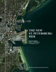
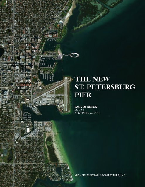
THE NEW<br />
ST. PETERSBURG<br />
PIER<br />
BASIS OF DESIGN<br />
BOOK 1<br />
NOVEMBER 26, 2012<br />
MICHAEL MALTZAN ARCHITECTURE, INC.
1<br />
BASIS OF DESIGN<br />
THE NEW ST. PETERSBURG PIER<br />
ST. PETERSBURG, FLORIDA<br />
BOOK 1<br />
NOVEMBER 26, 2012<br />
Prepared for<br />
The <strong>City</strong> <strong>of</strong> <strong>St</strong>. <strong>Petersburg</strong><br />
A/E Team<br />
Michael Maltzan Architecture, Inc.<br />
Buro Happold<br />
Wannemacher Jensen Architects, Inc.<br />
Tom Leader <strong>St</strong>udio<br />
Applied Technology Management<br />
Janicki Environmental, Inc.<br />
McLaren Engineering Group<br />
L’Observatoire International<br />
Construction Manager<br />
Skanska USA Building Inc.
CONTENT:<br />
BASIS OF DESIGN BOOK 1<br />
1<br />
2<br />
INTRODUCTION<br />
Executive <strong>St</strong>atement<br />
Background<br />
Purpose <strong>of</strong> Report<br />
Description <strong>of</strong> Work Performed<br />
Organization <strong>of</strong> Report<br />
EXECUTIVE SUMMARY<br />
Introduction<br />
Definitions<br />
Component Summary<br />
Cost Summary<br />
A/E Team Organizational Chart<br />
Project Schedule<br />
1 - 1<br />
1 - 2<br />
1 - 5<br />
1 - 6<br />
1 - 7<br />
2 - 1<br />
2 - 2<br />
2 - 8<br />
2 - 10<br />
2 - 12<br />
2 - 13<br />
3<br />
GENERAL PLANNING CRITERIA<br />
Introduction<br />
Public Outreach Notes<br />
Underwater Feature Outreach Summary<br />
Uplands Usage Suggestions<br />
Pier Advisory Task Force Report Summary<br />
Site and Urban Design Criteria<br />
Existing Infrastructure<br />
Architectural Criteria<br />
Engineering Criteria<br />
Marina Criteria<br />
Underwater Feature Criteria<br />
Fire and Life Safety Requirements<br />
Accessibility and Code Requirements<br />
Permitting and Demolition<br />
3 - 1<br />
3 - 4<br />
3 - 16<br />
3 - 17<br />
3 - 20<br />
3 - 22<br />
3 - 54<br />
3 - 61<br />
3 - 84<br />
3 - 104<br />
3 - 108<br />
3 - 122<br />
3 - 126<br />
3 - 136<br />
4<br />
COMPONENT PLANNING CRITERIA<br />
Introduction<br />
Program Components<br />
Existing Conditions<br />
Component Descriptions<br />
4 - 1<br />
4 - 2<br />
4 - 4<br />
4 - 9<br />
5<br />
BASIS OF DESIGN CONCEPT ANALYSIS<br />
Introduction<br />
Engineering Narrative<br />
Basis <strong>of</strong> Design Concept Plans and Diagrams<br />
5 - 1<br />
5 - 2<br />
5 - 5<br />
6<br />
CONSTRUCTION MANAGER AT RISK:<br />
PROJECT IMPLEMENTATION<br />
Cost Estimate Process<br />
Local Business Enterprise Participation<br />
Preliminary Schedule<br />
6 - 1<br />
6 - 4<br />
6 - 15<br />
7<br />
OPERATING EXPENSE AND MAINTENANCE<br />
ESTIMATES<br />
Operating Expense and Maintenance Estimates<br />
7 - 1<br />
MICHAEL MALTZAN ARCHITECTURE, INC. 1
BASIS OF DESIGN<br />
CONTENT:<br />
BASIS OF DESIGN BOOK 2<br />
A-O<br />
APPENDICES<br />
Appendix A<br />
<strong>St</strong>. <strong>Petersburg</strong> Pier Site Observations Report, June 27-28, 2012<br />
(Buro Happold)<br />
Appendix B<br />
Conceptual Fire Safety <strong>St</strong>rategy Presentation, September 26,<br />
2012 (Buro Happold)<br />
Appendix C<br />
Conceptual Fire Safety <strong>St</strong>rategy Presentation, Meeting Minutes<br />
(Buro Happold)<br />
Appendix D<br />
General Site Conditions Meeting Minutes, June 27, 2012<br />
(McLaren Engineering Group)<br />
Appendix E<br />
Environmental Resource Permit Application, August 2012<br />
Appendix F<br />
Underwater Feature Outreach Project: Meeting Minutes from<br />
Technical Workshops and Interviews<br />
Appendix G<br />
Hydrodynamics and Flushing <strong>of</strong> the Proposed Docking Facilities<br />
at <strong>St</strong>. <strong>Petersburg</strong> Pier<br />
Appendix H<br />
Pier Advisory Task Force Report<br />
Appendix I<br />
Vision/Guiding Principles and Context for the Preparation <strong>of</strong> a<br />
Downtown Waterfront Master Plan, December 2011<br />
Appendix J<br />
Skanska - Key Personnel<br />
Appendix K ASCE 24-05: Flood Resistant Design and<br />
Construction<br />
Appendix L<br />
<strong>City</strong> Pier Building Foundation Evaluation, March 1, 2010 (M<strong>of</strong>fatt<br />
and Nichol)<br />
Appendix M<br />
Cost Model (Skanska)<br />
Appendix N<br />
Life Cycle Cost Analysis Report<br />
Appendix O<br />
<strong>St</strong>. <strong>Petersburg</strong> Pier Request for Qualifications - International<br />
Design Competition<br />
2<br />
THE NEW ST. PETERSBURG PIER
LIST OF FIGURES<br />
1<br />
2<br />
3<br />
INTRODUCTION<br />
(none)<br />
EXECUTIVE SUMMARY<br />
Fig 2.1<br />
Fig 2.2<br />
Program Components <strong>of</strong> the New <strong>St</strong>. <strong>Petersburg</strong> Pier<br />
Current Project Schedule Agreed Upon by the A/E<br />
Team and the Construction Manager as <strong>of</strong> 11/19/2012<br />
GENERAL PLANNING CRITERIA<br />
Fig 3.1<br />
Fig 3.2<br />
Fig 3.3<br />
Fig 3.4<br />
Fig 3.5<br />
Fig 3.6<br />
Fig 3.7<br />
Fig 3.8<br />
Fig 3.9<br />
Fig 3.10<br />
Fig 3.11<br />
Fig 3.12<br />
Fig 3.13<br />
Fig 3.14<br />
Fig 3.15<br />
Fig 3.16<br />
Fig 3.17<br />
Fig 3.18<br />
Fig 3.19<br />
Fig 3.20<br />
Fig 3.21<br />
Fig 3.22<br />
Fig 3.23<br />
Fig 3.24<br />
Fig 3.25<br />
Fig 3.26<br />
Fig 3.27<br />
Fig 3.28<br />
Public Presentations and Information Sessions<br />
Site Context<br />
Current Uses <strong>of</strong> Site<br />
Existing Pier Head<br />
Historic Buildings<br />
Points <strong>of</strong> Interest Adjacent to the Pier<br />
Aerial View <strong>of</strong> Existing Pier<br />
View <strong>of</strong> Uplands, 2nd Avenue NE and North Basin<br />
West Elevation <strong>of</strong> Inverted Pyramid Building<br />
View <strong>of</strong> Demens Landing Park and Municipal Marina<br />
View <strong>of</strong> Skyline from Observation Deck<br />
View <strong>of</strong> Pier from South-West<br />
View <strong>of</strong> Inverted Pyramid from Pier Approach<br />
View <strong>of</strong> Pier Approach<br />
View <strong>of</strong> Inverted Pyramid from South<br />
Bird’s Eye View <strong>of</strong> Pier, Pier Approach and Uplands<br />
View <strong>of</strong> Skyline from Pier Approach<br />
Zoning Plan<br />
Height Limitations in Vicinity <strong>of</strong> Albert Whitted Airport<br />
Height Limitations<br />
2012 Seagrass and Essential Fish Habitat Survey<br />
Results<br />
Pier Deck Demolition Plan<br />
View Looking East Along 2nd Avenue NE<br />
Existing Site Access Routes<br />
Community Redevelopment Areas<br />
Datum Conversion Diagram<br />
Flood Insurance Rate Map for Pinellas County, Florida,<br />
and Incorporated Areas<br />
Wind Rose for Albert Whitted Airport<br />
Fig 3.29 Weather Data Gathered Between the Years 1981-2010<br />
for <strong>St</strong>. <strong>Petersburg</strong>, FL.<br />
Fig 3.30<br />
Soil Pr<strong>of</strong>ile Data<br />
MICHAEL MALTZAN ARCHITECTURE, INC. 3
BASIS OF DESIGN<br />
LIST OF FIGURES<br />
(continued)<br />
Fig 3.31<br />
Fig 3.32<br />
Fig 3.33<br />
Fig 3.34<br />
Fig 3.35<br />
Fig 3.36<br />
Fig 3.37<br />
Fig 3.38<br />
Fig 3.39<br />
Fig 3.40<br />
Fig 3.41<br />
Fig 3.42<br />
Fig 3.43<br />
Fig 3.44<br />
Fig 3.45<br />
Fig 3.46<br />
Fig 3.47<br />
Fig 3.48<br />
Fig 3.49<br />
Fig 3.50<br />
Fig 3.51<br />
Fig 3.52<br />
Fig 3.53<br />
Fig 3.54<br />
Fig 3.55<br />
Fig 3.56<br />
Fig 3.57<br />
Fig 3.58<br />
Fig 3.59<br />
Fig 3.60<br />
Fig 3.61<br />
Fig 3.62<br />
Fig 3.63<br />
Fig 3.64<br />
Fig 3.65<br />
Fig 3.66<br />
Hydrographic Survey<br />
Existing Site Services Plan<br />
Potential Photovoltaic Panel and Wind Turbine Array<br />
Potential Sustainable Lens Features: Examples <strong>of</strong><br />
Photovoltaic Panels<br />
Potential Sustainable Lens Features: Examples <strong>of</strong> Small<br />
Scale Wind Turbines<br />
Albert Whitted Airport Flight Paths<br />
Midday Sun Reflection <strong>St</strong>udy Along North-South Flight<br />
Path<br />
Summer Shading <strong>St</strong>udy<br />
Winter Shading <strong>St</strong>udy<br />
Example <strong>of</strong> Metal Panels on a Metal Frame Sub<br />
<strong>St</strong>ructure<br />
Example <strong>of</strong> Ipe Boardwalk<br />
Improved Pier Access Plan<br />
Pier Trolley Circuit<br />
Modified Parking for the New Pier<br />
Pier Activities<br />
Marina Phasing Diagram<br />
Example <strong>of</strong> Floating Dock System<br />
Serviceability <strong>of</strong> Floating Dock System<br />
Breakwater Capacity <strong>of</strong> Floating Dock System<br />
Marine Science in Classrooms<br />
Habitat Enhancement by Local Scientific Community<br />
Real-Time Monitoring and Imaging Technologies<br />
Linkage to the Underwater Feature via the Internet<br />
Habitat Sensitive Underwater Lighting<br />
Docent-Led Tours<br />
Enhanced Local Environment: Habitat Population and<br />
Protection<br />
Artificial Reef Construction Options Built Precedents<br />
Tampa Bay Artificial Reefs<br />
Plan Showing Existing Piles to Remain<br />
Plan Showing Reuse <strong>of</strong> Existing Piles<br />
Maximum Occupant Loads<br />
Example <strong>of</strong> Risk Category I <strong>St</strong>ructure<br />
Example <strong>of</strong> Risk Category II <strong>St</strong>ructure<br />
Example <strong>of</strong> Risk Category III <strong>St</strong>ructure<br />
Example <strong>of</strong> Risk Category IV <strong>St</strong>ructure<br />
Project Zones<br />
4<br />
THE NEW ST. PETERSBURG PIER
4<br />
5<br />
6<br />
7<br />
COMPONENT PLANNING CRITERIA<br />
Fig 4.1<br />
Fig 4.2<br />
Fig 4.3<br />
Fig 4.4<br />
Fig 4.5<br />
Fig 4.6<br />
Fig 4.7<br />
Fig 4.8<br />
Fig 4.9<br />
Fig 4.10<br />
Fig 4.11<br />
Fig 4.12<br />
Program Components <strong>of</strong> the New <strong>St</strong>. <strong>Petersburg</strong> Pier<br />
Comparison <strong>of</strong> Existing and New Piers in Plan<br />
Comparison <strong>of</strong> Existing and New Piers in Elevation<br />
Comparison <strong>of</strong> Existing Inverted Pyramid Building and<br />
New <strong>St</strong>. <strong>Petersburg</strong> Pier<br />
Welcome Mat Program Component and Related<br />
Subcomponents<br />
Hub Program Component and Related<br />
Subcomponents<br />
Overwater Drive Program Component and Related<br />
Subcomponents<br />
Overwater Bridge Program Component and Related<br />
Subcomponents<br />
Lens Canopy Program Component and Related<br />
Subcomponents<br />
Promontory Program Component and Related<br />
Subcomponents<br />
Marina Program Component and Related<br />
Subcomponents<br />
Underwater Feature Program Component and Related<br />
Subcomponents<br />
BASIS OF DESIGN CONCEPT ANALYSIS<br />
List <strong>of</strong> drawings provided on page 5-1<br />
CONSTRUCTION MANAGER AT RISK:<br />
PROJECT IMPLEMENTATION<br />
Fig 6.1 Screenshots <strong>of</strong> 3D Model Used for Costing<br />
Fig 6.2 Small Business Luncheons and Related Sponsored<br />
Events by Skanska<br />
Fig 6.3 Tampa Bay Area Skanska Projects<br />
Fig 6.4 Areas <strong>of</strong> Residence <strong>of</strong> Skanska’s Tampa Employees<br />
Fig 6.5 Port Canaveral Cruise Terminal No. 6<br />
Fig 6.6 Florida Polytech<br />
Fig 6.7 Sample Database <strong>of</strong> Pinellas County Subcontractors<br />
OPERATING EXPENSE AND MAINTENANCE ESTIMATES<br />
(none)<br />
MICHAEL MALTZAN ARCHITECTURE, INC. 5
1INTRODUCTION
EXECUTIVE STATEMENT<br />
The new <strong>St</strong>. <strong>Petersburg</strong> Pier is an extraordinary opportunity to<br />
create a new landmark that is representative <strong>of</strong> both the people<br />
and the <strong>City</strong> <strong>of</strong> <strong>St</strong>. <strong>Petersburg</strong>. As a team, we have come to<br />
know the <strong>City</strong>, its people and its landscape. We recognize the<br />
challenge <strong>of</strong> continuing the legacy first begun by William <strong>St</strong>raub,<br />
as well as the importance <strong>of</strong> this key public space for all <strong>of</strong> <strong>St</strong>.<br />
<strong>Petersburg</strong>. The <strong>City</strong> and the Pier have a shared identity, one<br />
that has become inextricably linked over time. Given this close<br />
relationship, it is especially important for this new icon to reflect<br />
and resonate with the <strong>City</strong> and its defining characteristic - its<br />
connection to the water.<br />
From the onset, the design team has strived to provide the <strong>City</strong><br />
with a Pier that is more than a simple, static object. Rather, our<br />
goal is to provide an accessible, flexible, and functional icon<br />
that is as much a public park as it is a breathtaking sculpture on<br />
the water. No longer a simple terminus, the Pier becomes an<br />
unparalleled place for new experiences from fishing to dining<br />
and falling in love.<br />
Throughout the Basis <strong>of</strong> Design effort, we have worked closely<br />
with the <strong>City</strong>, its citizens and a multitude <strong>of</strong> experts to identify<br />
goals and desires for the new <strong>St</strong>. <strong>Petersburg</strong> Pier. This process<br />
has strengthened and enriched the design, making it truly<br />
adapted to the <strong>City</strong> as a whole and serving as a beacon <strong>of</strong><br />
optimism for the future.<br />
This Report has been prepared by Michael Maltzan Architecture,<br />
Inc. and the A/E team for the <strong>City</strong> <strong>of</strong> <strong>St</strong>. <strong>Petersburg</strong>. The contents<br />
<strong>of</strong> the Basis <strong>of</strong> Design have been developed according to the<br />
<strong>City</strong>’s project requirements and form a living document that<br />
describes the technical approach and design parameters used<br />
for the project.<br />
While a tremendous amount <strong>of</strong> thought, effort and collaborative<br />
evaluation is embedded in this Report, the Basis <strong>of</strong> Design<br />
marks only the beginning <strong>of</strong> the design process, and a rigorous<br />
dialogue will be sustained throughout the development <strong>of</strong> the<br />
project.<br />
At this juncture, with the committed assistance <strong>of</strong> Skanska,<br />
the design team has been able to provide a project that<br />
is representative <strong>of</strong> the competition entry, and that meets<br />
the stipulated budget assigned to the cost <strong>of</strong> work. This<br />
achievement was no small feat and its significance should not be<br />
overlooked when evaluating this phase <strong>of</strong> the project. While a<br />
considerable amount <strong>of</strong> work, challenges, and tough decisions<br />
lie ahead, the team is prepared to undertake them with the<br />
<strong>City</strong> <strong>of</strong> <strong>St</strong>. <strong>Petersburg</strong> as a partner. Most importantly, the same<br />
skill and commitment will be applied to this project in the next<br />
phases in order to maintain the budget and the integrity <strong>of</strong> the<br />
design throughout the further development <strong>of</strong> the new Pier.<br />
MICHAEL MALTZAN ARCHITECTURE, INC. 1 - 1
BASIS OF DESIGN BOOK 1<br />
1 INTRODUCTION<br />
BACKGROUND<br />
The <strong>St</strong>. <strong>Petersburg</strong> Pier is the central element connecting<br />
downtown <strong>St</strong>. <strong>Petersburg</strong> with its waterfront and has become<br />
one <strong>of</strong> the <strong>City</strong>’s most iconic and visible structures. When William<br />
<strong>St</strong>raub became part owner and editor <strong>of</strong> the <strong>St</strong>. <strong>Petersburg</strong><br />
Times in 1901, he led the effort to set aside downtown waterfront<br />
property for the public to enliven community and generate<br />
well-being. This notion endures today with the <strong>City</strong>’s many<br />
initiatives for the preservation and enhancement <strong>of</strong> urban life<br />
and landscape.<br />
A number <strong>of</strong> piers have been constructed on the project site<br />
dating back to 1896. Notable structures include the Brantley<br />
Pier between 1896 and 1906, the Electric Pier between 1906 and<br />
1914, the Municipal Pier (constructed 10 feet north <strong>of</strong> the Electric<br />
Pier) between 1913 and 1921, the Million Dollar Pier between<br />
1926 and 1967, and the Inverted Pyramid building, which<br />
replaced the Million Dollar Pier building in 1973.<br />
Today, all superstructure components <strong>of</strong> the Pier approach<br />
and head, save for the 1973 Inverted Pyramid base, harken<br />
back to its original 1926 construction. Despite repairs, many<br />
<strong>of</strong> these superstructure elements suffer from concrete and<br />
structural deterioration due to corrosion, exposure and aging<br />
<strong>of</strong> the reinforcing steel causing spalls, cracks and delamination.<br />
Continued general repairs do not increase the load carrying<br />
capacity <strong>of</strong> the structure and are not a viable long-term solution.<br />
A structural assessment document prepared by M<strong>of</strong>fatt & Nichol<br />
appears as Appendix L <strong>of</strong> the BOD report.<br />
April 2005 - March 2009<br />
The <strong>City</strong> <strong>of</strong> <strong>St</strong>. <strong>Petersburg</strong> and Pinellas County approved<br />
amendments to the Intown Redevelopment Plan to provide<br />
$50 million for a Pier project. On December 11, 2008, <strong>City</strong><br />
Council met at a Pier Visioning Workshop and recommended<br />
the establishment <strong>of</strong> the Pier Advisory Task Force. On March<br />
19, 2009 <strong>City</strong> Council formally approved the creation <strong>of</strong> the<br />
Task Force and assigned its membership, to provide multiple<br />
redevelopment alternatives, review the status <strong>of</strong> the Pier,<br />
consult with citizens, persons with experience in architectural<br />
development matters and other appropriate persons.<br />
June 2010<br />
The Pier Advisory Task Force Final Report was released. <strong>City</strong><br />
Council authorized an international competition in July 2011 to<br />
enhance the creative process for the redevelopment <strong>of</strong> the <strong>St</strong>.<br />
<strong>Petersburg</strong> Pier, a process recommended by the Pier Advisory<br />
Task Force. The Task Force indicated that the conclusions in<br />
the report can be summed up by a quote from the Lambert<br />
Advisory: “the Pier would not be the Pier without a pier, and<br />
thereby the <strong>City</strong> would lose a major drawing card for Downtown<br />
<strong>St</strong>. <strong>Petersburg</strong>. What the configuration, size or length <strong>of</strong> the pier<br />
is [sic] less important from a marketing/positioning perspective<br />
than the fact that a pier in some form or fashion continues to<br />
exist” (Pier Advisory Task Force Report, p.40).<br />
1 - 2<br />
THE NEW ST. PETERSBURG PIER
The full report can be downloaded as a pdf at the following<br />
web address: http://www.stpete.org/news/the_pier/docs/Pier_<br />
Advisory_Task_Force_Final_Report_6_3_10.pdf<br />
June 2011<br />
The <strong>City</strong> <strong>of</strong> <strong>St</strong>. <strong>Petersburg</strong> released a request for qualifications<br />
(RFQ) document for a design competition. <strong>St</strong>age 1 <strong>of</strong> the<br />
competition called for multi-disciplinary teams interested<br />
in being considered for the services <strong>of</strong> redeveloping the <strong>St</strong>.<br />
<strong>Petersburg</strong> Pier to register and submit a design approach,<br />
relevant project examples and team background and<br />
experience. Concurrently a five (5) member jury reflecting a<br />
diverse range <strong>of</strong> expertise and perspective was assembled<br />
and approved by <strong>City</strong> Council to review the applicants and<br />
select the winning design. The jury was comprised <strong>of</strong> a <strong>City</strong><br />
Council representative, a County commissioner - both <strong>City</strong> <strong>of</strong> <strong>St</strong>.<br />
<strong>Petersburg</strong> residents - and three experts in the respective fields<br />
<strong>of</strong> architecture, urban design and planning, and development/<br />
economics. Of the three experts, one was from Tampa while the<br />
other two were from outside the <strong>St</strong>ate <strong>of</strong> Florida.<br />
August 2011<br />
From a group <strong>of</strong> twenty-three (23) international applicants,<br />
nine (9) were shortlisted for further consideration by the Jury.<br />
The <strong>City</strong> then invited a shortlist <strong>of</strong> three (3) teams <strong>of</strong> Finalists<br />
(architectural firms with their respective team members) to<br />
submit a Design Concept in <strong>St</strong>age 2 <strong>of</strong> the International Design<br />
Competition.<br />
The finalists selected were Michael Maltzan Architecture,<br />
Inc., Bjarke Ingels Group (BIG) and West 8 Urban Design and<br />
Landscape Architecture. The design concept submission<br />
deadline occurred on November 29, 2011. The three groups<br />
were asked to consider the area over the water, the 21 acre<br />
Uplands directly west <strong>of</strong> the Pier and connections to the larger<br />
urban context. <strong>St</strong>age 2 <strong>of</strong> the competition included a two (2) day<br />
briefing and ten (10) weeks to prepare a vision and concept for<br />
the project. http://www.stpete.org/pierdesign/stage_2.asp<br />
January 20, 2012<br />
The <strong>St</strong>. <strong>Petersburg</strong> Pier competition jury unanimously voted<br />
Michael Maltzan Architecture’s Lens design as the top concept.<br />
The ranking served as recommendation that the Lens design<br />
concept go before the <strong>St</strong>. <strong>Petersburg</strong> <strong>City</strong> Council for approval<br />
and authorization to proceed with negotiations with Michael<br />
Maltzan Architecture, Inc. for final design.<br />
February 2, 2012<br />
The <strong>St</strong>. <strong>Petersburg</strong> <strong>City</strong> Council approved the Lens design<br />
concept and authorized city staff to initiate Architectural/<br />
Engineering Services contract negotiations with Michael Maltzan<br />
Architecture, Inc.<br />
MICHAEL MALTZAN ARCHITECTURE, INC. 1 - 3
BASIS OF DESIGN BOOK 1<br />
1 INTRODUCTION<br />
BACKGROUND (continued)<br />
May 17, 2012<br />
The <strong>St</strong>. <strong>Petersburg</strong> <strong>City</strong> Council approved the Architectural/<br />
Engineering Pr<strong>of</strong>essional Services contract. The contract includes<br />
five (5) phases as follows:<br />
• Phase I -- Basis <strong>of</strong> Design<br />
• Phase II -- Schematic Design<br />
• Phase III -- Design Development<br />
• Phase IV -- Construction Documents<br />
• Phase V -- Construction Administration<br />
July 9 - 11, 2012<br />
BOD kick<strong>of</strong>f meetings between the <strong>City</strong> <strong>of</strong> <strong>St</strong>. <strong>Petersburg</strong> staff<br />
and the A/E team were held at the <strong>of</strong>fice <strong>of</strong> Michael Maltzan<br />
Architecture, Inc. in Los Angeles.<br />
September 13, 2012<br />
The A/E team presented BOD midterm updates to <strong>City</strong> Council<br />
in <strong>St</strong>. <strong>Petersburg</strong>.<br />
October 4, 2012<br />
The <strong>City</strong> retained the services <strong>of</strong> Skanska with <strong>City</strong> Council’s<br />
approval <strong>of</strong> the Construction Manager contract.<br />
December 4, 2012<br />
The A/E team will present the final BOD presentation to <strong>City</strong><br />
Council in <strong>St</strong>. <strong>Petersburg</strong>.<br />
1 - 4<br />
THE NEW ST. PETERSBURG PIER
PURPOSE OF REPORT<br />
The purpose <strong>of</strong> this BOD Report is as follows:<br />
• To provide a program narrative that identifies the<br />
concept’s key components.<br />
• To describe the design intent and establish design<br />
criteria. It is not intended to set definitive design<br />
decisions either architecturally or structurally.<br />
• To provide drawings sufficient for description <strong>of</strong> the<br />
scope and concept.<br />
• To provide documentation <strong>of</strong> the A/E team’s public<br />
outreach with the local community and marine science<br />
community.<br />
• To provide a cost model prepared by the Construction<br />
Manager with the A/E team.<br />
• To establish the technical criteria and benchmarks<br />
for building code, occupancy, egress, fire and safety<br />
compliance.<br />
• To provide estimated costs for the operation and<br />
maintenance <strong>of</strong> the project.<br />
• To identify future programmatic and planning<br />
opportunities for the Uplands area that are suggestions<br />
for inclusion in the <strong>City</strong>’s Downtown Waterfront Master<br />
Plan.<br />
MICHAEL MALTZAN ARCHITECTURE, INC. 1 - 5
BASIS OF DESIGN BOOK 1<br />
1 INTRODUCTION<br />
DESCRIPTION OF<br />
WORK PERFORMED<br />
The goal <strong>of</strong> Phase I, BOD (BOD), is to develop a clearly defined,<br />
comprehensive set <strong>of</strong> basic design criteria that the A/E team<br />
will work from in the subsequent four (4) design phases. The A/E<br />
team has worked closely with the <strong>City</strong> appointed Construction<br />
Manager (CM) throughout BOD to ensure that the Lens concept<br />
complies with the <strong>City</strong>’s $40.5 million budget for the demolition<br />
<strong>of</strong> the existing Pier and construction <strong>of</strong> the new Pier.<br />
Michael Maltzan Architecture, Inc. and the members <strong>of</strong> the A/E<br />
team commenced work on the BOD Report in July 2012. Since<br />
then the team has accomplished a number <strong>of</strong> goals, namely the<br />
development and submission <strong>of</strong> the Environmental Resource<br />
Permits for the demolition <strong>of</strong> the existing Pier and construction<br />
<strong>of</strong> the new Pier, as well as assisting with the preparation <strong>of</strong><br />
demolition bid documents. Additionally, the A/E team has held<br />
38 public outreach meetings to date, met with individuals from<br />
the marine science community and worked closely with <strong>City</strong> <strong>of</strong><br />
<strong>St</strong>. <strong>Petersburg</strong> representatives to refine the design and identify<br />
project goals and technical criteria. Through collaboration with<br />
Skanska, a highly detailed cost model has been developed,<br />
allowing for accurate order <strong>of</strong> magnitude pricing and cost<br />
control from the outset <strong>of</strong> the project.<br />
The overall process <strong>of</strong> developing this document was highly<br />
collaborative and participatory, involving the efforts <strong>of</strong> all<br />
members <strong>of</strong> the team and key staff from the <strong>City</strong> <strong>of</strong> <strong>St</strong>.<br />
<strong>Petersburg</strong>.<br />
The BOD process provides for delivery <strong>of</strong> completed<br />
BOD documents by Monday, November 26, 2012, and the<br />
presentation <strong>of</strong> the BOD Report by Tuesday, December 4, 2012.<br />
Once the <strong>City</strong> has received and approved all <strong>of</strong> the deliverables,<br />
with any revisions, the <strong>City</strong> will authorize the A/E team, in writing,<br />
to commence with the Schematic Design phase. Any comments<br />
as part <strong>of</strong> the written authorization to proceed to the Schematic<br />
Design phase will become a part <strong>of</strong> the required services and<br />
deliverables to be provided by the A/E team in the Schematic<br />
Design phase.<br />
1 - 6<br />
THE NEW ST. PETERSBURG PIER
ORGANIZATION OF REPORT<br />
The BOD Report is organized into seven (7) major sections<br />
followed by Appendices.<br />
1 Introduction<br />
Includes the background <strong>of</strong> the project, a definition <strong>of</strong> the<br />
purpose <strong>of</strong> the BOD Report, a description <strong>of</strong> the work performed<br />
and the organization <strong>of</strong> the report and project.<br />
2 Executive Summary<br />
Includes a comprehensive list <strong>of</strong> definitions <strong>of</strong> key words<br />
pertaining to the project and the BOD Report; the A/E team’s<br />
organizational chart; a quantitative summary <strong>of</strong> component<br />
space requirements; a summary <strong>of</strong> project costing and the<br />
project schedule.<br />
3 General Planning Criteria<br />
Includes broad conceptual statements related to the Pier as a<br />
whole and will influence the planning and design processes in<br />
the upcoming phases <strong>of</strong> the project. It is not intended to set<br />
definitive design decisions, but to establish the relationships<br />
between major parts. This section also establishes the technical<br />
criteria and benchmarks for building code, permitting,<br />
occupancy/egress, fire and safety compliance, and summarizes<br />
relevant design information based on the input <strong>of</strong> the public, the<br />
marine science community and the Pier Advisory Task Force.<br />
4 Component Planning Criteria<br />
Includes a description <strong>of</strong> eight (8) individual program<br />
components comprising the project. This section defines the<br />
activities and functions <strong>of</strong> each program component in addition<br />
to its users, character, physical space estimates and technical<br />
requirements.<br />
5 Basis <strong>of</strong> Design Concept Analysis<br />
Includes BOD architectural drawings and diagrams.<br />
6 Construction Manager at Risk: Project Implementation<br />
Includes project implementation information and a preliminary<br />
schedule. The detailed cost model developed by Construction<br />
Manager at Risk is included as Appendix M.<br />
7 Operating Expense and Maintenance Estimates<br />
Includes estimated operation and maintenance costs for the<br />
project.<br />
MICHAEL MALTZAN ARCHITECTURE, INC. 1 - 7
BASIS OF DESIGN BOOK 1<br />
1 INTRODUCTION<br />
ORGANIZATION OF REPORT<br />
(continued)<br />
Appendices<br />
Provide supporting documentation to the sections described<br />
above, including:<br />
• Appendix A: <strong>St</strong>. <strong>Petersburg</strong> Pier Site Observations<br />
Report, June 27-28, 2012 (Buro Happold)<br />
• Appendix B: Conceptual Fire Safety <strong>St</strong>rategy<br />
Presentation, September 26, 2012 (Buro Happold)<br />
• Appendix C: Conceptual Fire Safety <strong>St</strong>rategy<br />
Presentation, Meeting Minutes (Buro Happold)<br />
• Appendix D: General Site Conditions Meeting Minutes,<br />
June 27, 2012 (McLaren Engineering Group)<br />
• Appendix E: Environmental Resource Permit Application,<br />
August 2012<br />
• Appendix F: Underwater Feature Outreach Project:<br />
Meeting Minutes from Technical Workshops and<br />
Interviews<br />
• Appendix G: Hydrodynamics and Flushing <strong>of</strong> the<br />
Proposed Docking Facilities at <strong>St</strong>. <strong>Petersburg</strong> Pier<br />
• Appendix H: Pier Advisory Task Force Report<br />
• Appendix I: Vision/Guiding Principles and Context for<br />
the Preparation <strong>of</strong> a Downtown Waterfront Master Plan,<br />
December 2011<br />
• Appendix J: Skanska - Key Personnel<br />
• Appendix K: ASCE 24-05: Flood Resistant Design and<br />
Construction<br />
• Appendix L: <strong>City</strong> Pier Building Foundation Evaluation,<br />
March 1, 2010 (M<strong>of</strong>fatt & Nichol)<br />
• Appendix M: Cost Model (Skanska)<br />
• Appendix N: Life Cycle Cost Analysis Report<br />
• Appendix O: <strong>St</strong>. <strong>Petersburg</strong> Pier Request for<br />
Qualifications - International Design Competition<br />
1 - 8<br />
THE NEW ST. PETERSBURG PIER
2EXECUTIVE<br />
SUMMARY
INTRODUCTION<br />
This section includes a series <strong>of</strong> tables summarizing key project<br />
scope factors as well as general information concerning the new<br />
Pier, as follows:<br />
• Definitions<br />
Lexicon <strong>of</strong> key words used within the BOD Report.<br />
• Component Summary<br />
Space requirements for each program component.<br />
• Cost Summary<br />
Costs attributed to the new Pier in CSI format.<br />
• A/E Organizational Chart<br />
Organization <strong>of</strong> Architecture and Engineering team for<br />
the project.<br />
• Project Schedule<br />
Schedule and description <strong>of</strong> all phases and tasks <strong>of</strong> the<br />
project.<br />
MICHAEL MALTZAN ARCHITECTURE, INC. 2 - 1
BASIS OF DESIGN BOOK 1<br />
2 EXECUTIVE SUMMARY<br />
DEFINITIONS<br />
Architectural Phases<br />
Basis <strong>of</strong> Design (BOD): First phase <strong>of</strong> the design project. Living<br />
document developed by the Architecture and Engineering team<br />
that translates the <strong>City</strong> <strong>of</strong> <strong>St</strong>. <strong>Petersburg</strong>’s needs into building<br />
components and describes the technical approach and design<br />
parameters used for the project.<br />
Schematic Design (SD): Preparation <strong>of</strong> drawings and other<br />
documents illustrating the scale and relationship <strong>of</strong> project<br />
components.<br />
Design Development (DD): Development <strong>of</strong> plans and<br />
elevations for the project. Drawings establishing all major<br />
elements and outline specifications are prepared and a revised<br />
statement <strong>of</strong> construction cost is produced.<br />
Construction Documents (CD): Preparation <strong>of</strong> working drawings,<br />
specifications and bidding information.<br />
Construction Administration (CA): Construction <strong>of</strong> project as<br />
specified in the CD phase by the Construction Manager with<br />
assistance from the Architect. Additional clarifications to the<br />
drawings issued in the CD phase are made through the issuance<br />
<strong>of</strong> architectural sketches.<br />
A/E Team<br />
Architecture and Engineering team designing the new Pier.<br />
American Association <strong>of</strong> <strong>St</strong>ate Highway and Transportation<br />
Officials (AASHTO)<br />
A standards setting body which publishes specifications, test<br />
protocols and guidelines which are used in highway design and<br />
construction throughout the United <strong>St</strong>ates. The association<br />
represents not only highways but air, rail, water, and public<br />
transportation as well.<br />
American Society for Testing and Materials (ASTM)<br />
International standards organization that develops and publishes<br />
voluntary consensus technical standards for a wide range <strong>of</strong><br />
materials, products, systems and services.<br />
Americans with Disabilities Act (ADA)<br />
Legislation enacted by the U.S. federal government in 1991 with<br />
the goal <strong>of</strong> removing barriers that limit the engagement <strong>of</strong> an<br />
individual with a disability in normal daily activity in the physical,<br />
public environment.<br />
Base Flood Elevation (BFE)<br />
Water surface elevation corresponding to a flood having a<br />
one percent probability <strong>of</strong> being equaled or exceeded in a<br />
given year as defined in the FEMA Flood Map. The base flood<br />
elevation for the site <strong>of</strong> the new Pier is +8 ft. NAVD 88.<br />
2 - 2<br />
THE NEW ST. PETERSBURG PIER
Bent<br />
Part <strong>of</strong> a bridge substructure. A rigid frame commonly made <strong>of</strong><br />
reinforced concrete or steel that supports a vertical load and is<br />
placed transverse to the length <strong>of</strong> a structure.<br />
Biome<br />
Large naturally occurring community <strong>of</strong> flora and fauna<br />
occupying a major habitat.<br />
Bulkhead<br />
Retaining wall along a waterfront. Synonymous with ‘seawall’.<br />
Canopy<br />
Ro<strong>of</strong>like projection or shelter.<br />
Capital Improvement Plan (CIP)<br />
Short range plan which identifies capital projects and equipment<br />
purchases, provides a planning schedule and identifies options<br />
for financing the plan.<br />
Coastal High Hazard Zone<br />
Area particularly vulnerable to the effects <strong>of</strong> coastal flooding.<br />
Community Redevelopment Area (CRA)<br />
Area designated for redevelopment by a municipality or county<br />
after a determination that “slum and blight” criteria have been<br />
met, as established in Chapter 163 Part III <strong>of</strong> the Florida <strong>St</strong>atutes,<br />
traditionally funded by Tax Increment Financing (TIF).<br />
Component<br />
Discrete grouping <strong>of</strong> spaces and activities that are physically<br />
related, composing an area <strong>of</strong> the new Pier designed by Michael<br />
Maltzan Architecture, Inc.<br />
Construction Manager (CM)<br />
The construction team that will lead the construction efforts <strong>of</strong><br />
the various subcontractors and hold the contract with the <strong>City</strong> <strong>of</strong><br />
<strong>St</strong>. <strong>Petersburg</strong> to build the new Pier. The Construction Manager<br />
for the Pier is Skanska USA, Inc.<br />
Construction Manager at Risk (CMR)<br />
Delivey method that entails a commitment by the construction<br />
manager to deliver the project within a Guaranteed Maximum<br />
Price (GMP).<br />
Construction Specifications Institute (CSI)<br />
An organization that maintains and advances the standardization<br />
<strong>of</strong> construction language as pertains to building specifications.<br />
CSI authored MasterFormat, which is an indexing system<br />
for organizing construction data, particularly construction<br />
specifications.<br />
MICHAEL MALTZAN ARCHITECTURE, INC. 2 - 3
BASIS OF DESIGN BOOK 1<br />
2 EXECUTIVE SUMMARY<br />
DEFINITIONS (continued)<br />
Design Flood Elevation (DFE)<br />
Elevation <strong>of</strong> the 100-year storm as defined in FEMA Flood<br />
Insurance <strong>St</strong>udies or, in areas without FEMA floodplains, the<br />
elevation <strong>of</strong> the 25-year storm.<br />
Estuary<br />
Tidal mouth <strong>of</strong> a large river or body <strong>of</strong> water, where the tide<br />
meets the stream.<br />
Federal Emergency Management Agency (FEMA)<br />
Agency that coordinates the federal government’s role in<br />
preparing for, preventing, mitigating the effects <strong>of</strong>, and<br />
recovering from all domestic disasters, whether natural or manmade.<br />
Flood Hazard Area<br />
Areas that are subject to flooding.<br />
Florida Accessibility Code for Building Construction (FACBC)<br />
<strong>St</strong>ate <strong>of</strong> Florida Legislation, adopted in 2012, that contains<br />
guidelines and provisions more stringent than the Federal<br />
Americans with Disabilities Act (ADA).<br />
Geotechnical Investigation<br />
Used to obtain information on the physical properties <strong>of</strong> soil<br />
and rock around a site to design earthworks and foundations for<br />
proposed structures and for repair <strong>of</strong> distress to earthworks and<br />
structures caused by subsurface conditions.<br />
Hub<br />
Program component <strong>of</strong> the new Pier located on the Uplands<br />
serving as the main retail and dining attraction for the project.<br />
HVAC<br />
Term used to refer to the mechanical systems which heat,<br />
cool, filter or dehumidify air in a room or building. Acronym for<br />
‘heating, ventilation and air conditioning’.<br />
Iconic Architecture<br />
Architecture that is beautiful in form, serves a useful purpose and<br />
creates a sense <strong>of</strong> place by contributing to the public realm while<br />
being unique, not ordinary and having never been done before.<br />
Intertidal Zone<br />
Area that is exposed to the air at low tide and underwater at<br />
high tide.<br />
Intermodal<br />
Accommodation <strong>of</strong> multiple means <strong>of</strong> transportation, including<br />
accessible, pedestrian, bicycle and vehicular.<br />
2 - 4<br />
THE NEW ST. PETERSBURG PIER
Leadership in Energy and Environmental Design (LEED)<br />
Suite <strong>of</strong> rating systems for the design, construction and<br />
operation <strong>of</strong> high performance green buildings, homes and<br />
neighborhoods. Developed by the U.S. Green Building Council,<br />
LEED is intended to provide building owners and operators a<br />
concise framework for identifying and implementing practical<br />
and measurable green building design, construction, operations<br />
and maintenance solutions.<br />
Lens<br />
Term referring to the iconic design <strong>of</strong> the new Pier by Michael<br />
Maltzan Architecture, Inc.<br />
Mean Sea Level (MSL)<br />
A tidal datum. The arithmetic mean <strong>of</strong> hourly heights observed<br />
over the National Tidal Datum Epoch. Shorter series are<br />
specified in the name; e.g., monthly mean sea level and yearly<br />
mean sea level.<br />
Millage Rate<br />
Amount per $1,000 that is used to calculate taxes on property.<br />
National Electrical Manufacturers Association (NEMA)<br />
Assocation <strong>of</strong> electrical equipment manufacturers for the<br />
development <strong>of</strong> technical standards that are in the best interests<br />
<strong>of</strong> the industry and users.<br />
National Geodetic Vertical Datum <strong>of</strong> 1929 (NGVD 29)<br />
A fixed reference adopted as a standard geodetic datum for<br />
elevations determined by leveling. The geodetic datum is fixed<br />
and does not take into account the changing stands <strong>of</strong> sea<br />
level. Because many variables affect sea level and because the<br />
geodetic datum represents a best fit over a broad area, the<br />
relationship between the geodetic datum and local mean sea<br />
level (MSL) is not consistent from one location in either time or<br />
space. NGVD (1929) has been superseded for use by the North<br />
American Vertical Datum <strong>of</strong> 1988.<br />
North American Vertical Datum (NAVD 88)<br />
A fixed reference for elevations determined by geodetic leveling.<br />
Established in 1991 by the minimum-constraint adjustment <strong>of</strong><br />
the Canadian-Mexican-U.S. leveling observations, which held<br />
the fixed height <strong>of</strong> the primary tidal bench mark, referenced to<br />
the new International Great Lakes Datum <strong>of</strong> 1985 local mean sea<br />
level height value, at Father Point/Rimouski, Quebec, Canada.<br />
Piazza<br />
Public square or gathering place.<br />
Pier Approach<br />
Area <strong>of</strong> the existing Pier that describes the approximately 1/4<br />
mile long bridge portion <strong>of</strong> the Pier between the Uplands<br />
seawall and the Pier head.<br />
MICHAEL MALTZAN ARCHITECTURE, INC. 2 - 5
BASIS OF DESIGN BOOK 1<br />
2 EXECUTIVE SUMMARY<br />
DEFINITIONS (continued)<br />
Pier Head<br />
Portion <strong>of</strong> the existing Pier that describes the large rectangular<br />
area at the eastern end <strong>of</strong> the 1926 Pier approach.<br />
Project<br />
Term used in the Basis <strong>of</strong> Design document to describe the<br />
new Pier designed by Michael Maltzan Architecture, Inc. in<br />
all <strong>of</strong> its scope, inclusive <strong>of</strong> all design components and site<br />
improvements.<br />
Promontory<br />
High ridge <strong>of</strong> land that juts out into a large body <strong>of</strong> water.<br />
Return Period<br />
Estimate <strong>of</strong> the interval <strong>of</strong> time between flood <strong>of</strong> a certain<br />
intensity or size.<br />
Reef<br />
A ridge <strong>of</strong> rock, coral, or sand just above or below the surface <strong>of</strong><br />
a body <strong>of</strong> water.<br />
Risk Category<br />
Categorization <strong>of</strong> buildings and other structures for the<br />
determination <strong>of</strong> flood, wind, snow, ice and earthquake loads<br />
based on the risk associated with unacceptable performance.<br />
Scour<br />
The removal by hydrodynamic forces <strong>of</strong> bed material in the<br />
vicinity <strong>of</strong> coastal structures.<br />
Seagrass<br />
Underwater flowering plants that live in protected bays, lagoons<br />
and other shallow coastal waters. This grass-like vegetation<br />
forms small patchy beds that can develop into expansive<br />
meadows. Seagrasses perform a number <strong>of</strong> ecological functions<br />
such as improving water quality, contributing to the marine food<br />
web and stabilizing loose sediment.<br />
Seawall<br />
See Bulkhead.<br />
Shell Space<br />
Enclosed space with floors, windows, walls and ro<strong>of</strong> that may<br />
include electrical or plumbing improvements but requires tenant<br />
improvements before it is ready to be occupied.<br />
Tax Increment Financing (TIF)<br />
Mechanism that allows local governments to use future<br />
projected taxes generated within an approved Community<br />
Redevelopment Area to finance public improvement projects.<br />
2 - 6<br />
THE NEW ST. PETERSBURG PIER
Underwater Feature<br />
Future program component <strong>of</strong> the new Pier serving as an<br />
educational attraction that highlights the marine environment<br />
and marine restoration while contributing to the community.<br />
Uplands<br />
Landmass connecting the existing pier approach to the <strong>City</strong><br />
and Bay Shore Drive NE. Extending 2nd Avenue NE into Tampa<br />
Bay, it is also the site <strong>of</strong> Spa Beach, the Pelican Parking Lot, the<br />
Dolphin Parking Lot and the <strong>St</strong>. <strong>Petersburg</strong> Museum <strong>of</strong> History.<br />
Wave Attenuator<br />
Man-made structure used to extract the energy from incoming<br />
waves.<br />
MICHAEL MALTZAN ARCHITECTURE, INC. 2 - 7
BASIS OF DESIGN BOOK 1<br />
2 EXECUTIVE SUMMARY<br />
COMPONENT SUMMARY<br />
The basic elements <strong>of</strong> the project were generally depicted in the<br />
material submitted by the A/E team for the international design<br />
competition and shall be refined and further developed in<br />
accordance with the Agreement with the <strong>City</strong> <strong>of</strong> <strong>St</strong>. <strong>Petersburg</strong>.<br />
Program components for the new Pier include:<br />
• Welcome Mat - 47,400 SF<br />
Open civic space functioning as the site <strong>of</strong> public<br />
interface between the <strong>City</strong> and the Pier<br />
• Hub - 22,350 SF<br />
Planned retail and dining attractor for private sector<br />
development located on the Uplands near the Welcome<br />
Mat<br />
• Overwater Drive - 34,050 SF<br />
Looping bridge serving as a circuit from land to water<br />
and accommodating some vehicular traffic<br />
• Overwater Bridge - 20,100 SF<br />
Looping bridge serving as a circuit from land to water<br />
accommodating pedestrian traffic<br />
• Lens Canopy - 54,550 SF<br />
Visual focal point <strong>of</strong> the project that provides shade<br />
• Promontory - 18,000 SF<br />
Platform beneath Lens Canopy for public gathering and<br />
direct access to water<br />
• Marina - 9,150 SF<br />
Central space within the Lens that accommodates<br />
aquatic vehicles and other visitor attractions<br />
• Underwater Feature (future component) - 20,000 SF<br />
Public attraction that highlights the relationship <strong>of</strong> the<br />
people <strong>of</strong> <strong>St</strong>. <strong>Petersburg</strong>’s to the Bay and its ecology<br />
2 - 8<br />
THE NEW ST. PETERSBURG PIER
LENS CANOPY<br />
WELCOME MAT<br />
OVERWATER<br />
BRIDGE<br />
LENS MARINA<br />
PROMONTORY<br />
HUB<br />
OVERWATER<br />
DRIVE<br />
UNDERWATER<br />
FEATURE<br />
Figure 2.1 Program Components <strong>of</strong> the new Pier<br />
MICHAEL MALTZAN ARCHITECTURE, INC. 2 - 9
BASIS OF DESIGN BOOK 1<br />
2 EXECUTIVE SUMMARY<br />
COST SUMMARY<br />
Project Budget<br />
The total project budget for the new <strong>St</strong>. <strong>Petersburg</strong> Pier is<br />
fifty million dollars ($50,000,000) as set forth in the <strong>City</strong> <strong>of</strong> <strong>St</strong>.<br />
<strong>Petersburg</strong>’s Intown Redevelopment Plan and subsequent<br />
amendments. The project budget is comprised <strong>of</strong> several<br />
categories <strong>of</strong> expenditures required to design, administer and<br />
construct the new <strong>St</strong>. <strong>Petersburg</strong> Pier. The breakdown <strong>of</strong> the<br />
total project budget is as follows:<br />
Project Hard Cost<br />
Demolition Budget $ 3,075,000<br />
Construction Cost Budget $ 36,950,000<br />
Geotechnical Testing $ 500,000<br />
Project Hard Cost Subtotal $ 40,525,000<br />
Project S<strong>of</strong>t Cost<br />
Design and Predevelopment Budget $ 6,595,000<br />
Administration, Inspection & Contingency $ 2,880,000<br />
Project S<strong>of</strong>t Cost Subtotal $ 9,475,000<br />
Total Project Budget $ 50,000,000<br />
Construction Cost Budget<br />
The construction cost budget is defined as the total budget<br />
available to the Construction Manager to construct the new <strong>St</strong>.<br />
<strong>Petersburg</strong> Pier pursuant to the Guaranteed Maximum Price<br />
Construction Manager at Risk Contract. The construction cost<br />
budget does not include the demolition cost, or any <strong>of</strong> the<br />
s<strong>of</strong>t cost required to design and administer the project. The<br />
construction cost budget is $36,950,000.<br />
Project Cost Plan<br />
The development <strong>of</strong> a project cost plan was a key requirement<br />
<strong>of</strong> the BOD phase. The purpose <strong>of</strong> the cost plan is to ensure<br />
that the new Pier concept can be constructed by a Construction<br />
Manager within the construction cost budget. The project cost<br />
plan is determined by the cost <strong>of</strong> the work plus the general<br />
conditions, the CM fee, bonds, insurance, permitting cost and<br />
contingencies required to construct the new Pier.<br />
2 - 10<br />
THE NEW ST. PETERSBURG PIER
Cost Summary (CSI Format)<br />
The basic elements <strong>of</strong> the project that constitute the Cost <strong>of</strong> the<br />
Work are as follows:<br />
1 General Requirements $ 315,000<br />
2 Existing Conditions $ 263,052<br />
3 Concrete $ 6,545,439<br />
4 Masonry $ 77,599<br />
5 Metals $ 6,377,977<br />
6 Wood, Plastics and Composites $ 124,378<br />
7 Thermal and Moisture Protection $ 5,063,791<br />
8 Openings $ 86,652<br />
9 Finishes $ 36,224<br />
10 Specialties $ 55,309<br />
11 Furnishings $ 170,152<br />
12 Special Construction $ 1,395,775<br />
13 Conveying Equipment $ 133,571<br />
14 Fire Suppression $ 5,672<br />
15 Plumbing $ 141,449<br />
16 Heating, Ventilating and Air Conditioning $ 18,151<br />
17 Electrical $ 2,357,373<br />
18 Communications $ 269,207<br />
19 Earthwork $ 79,000<br />
20 Exterior Improvements $ 4,633,855<br />
21 Utilities $ 751,695<br />
Subtotal $ 30,820,502<br />
22 General Conditions, CM Fee, Construction<br />
Bonds, Insurance, Permitting Cost,<br />
Contingencies $ 6,129,498<br />
Construction Cost Budget $ 36,950,000<br />
MICHAEL MALTZAN ARCHITECTURE, INC. 2 - 11
BASIS OF DESIGN BOOK 1<br />
2 EXECUTIVE SUMMARY<br />
A/E TEAM<br />
ORGANIZATIONAL CHART<br />
CITY OF ST. PETERSBURG<br />
SKANSKA USA BUILDING, INC.<br />
CONSTRUCTION MANAGER / TAMPA, FL<br />
CHUCK JABLON<br />
OPERATIONS VICE PRESIDENT<br />
BRIAN COAKLEY<br />
VICE PRESIDENT OF PRECONSTRUCTION<br />
ST. PETERSBURG, FL<br />
PETE KARAMITSANIS<br />
PROJECT ADVISOR / TAMPA, FL<br />
MOFFAT & NICHOL ENGINEERS<br />
ENVIRONMENTAL PLANNING / TAMPA, FL<br />
MICHAEL HERRMAN<br />
WILLIS CONSTRUCTION<br />
OPERATING EXPENSE ANALYSIS / MAITLAND, FL<br />
MICHAEL MALTZAN ARCHITECTURE, INC.<br />
ARCHITECT OF RECORD / LOS ANGELES, CA<br />
MICHAEL MALTZAN, FAIA<br />
DESIGN PRINCIPAL<br />
TIM WILLIAMS<br />
PROJECT DIRECTOR<br />
WIL CARSON, LEED AP<br />
PROJECT DESIGNER<br />
ANDREW SMITH RASMUSSEN<br />
JOB CAPTAIN<br />
LISA MADONNA<br />
PROJECT COORDINATO R<br />
BURO HAPPOLD<br />
SMEP, CIVIL, CODE CONSULTING /<br />
FIRE AND LIFE SAFETY ENGINEER<br />
NEW YORK, NY / LOS ANGELES, CA<br />
CRAIG SCHWITTER<br />
PRINCIPAL IN CHARGE<br />
NEIL PORTO<br />
PRINCIPAL STRUCTURE<br />
JP CHAKAR<br />
ASSOCIATE PRINCIPAL<br />
CARL KEOGH<br />
ASSOCIATE<br />
MCLAREN ENGINEERING GROUP<br />
MARINE STRUCTURAL / ORLANDO, FL<br />
WANNEMACHER JENSEN ARCHITECTS, INC.<br />
ASSOCIATE ARCHITECT / ST. PETERSBURG, FL<br />
LISA WANNEMACHER<br />
PRINCIPAL<br />
JASON JENSEN<br />
PROJECT DIRECTOR<br />
TOM LEADER STUDIO<br />
LANDSCAPE ARCHITECT / BERKELY, CA<br />
TOM LEADER<br />
PRINCIPAL<br />
KATHRYN DRINKHOUSE<br />
ASSOCIATE / TECHNICAL DIRECTOR<br />
APPLIED TECHNOLOGY & MANAGEMENT<br />
MARINA / GAINESVILLE, FL<br />
ROBERT SEMMES<br />
PRINCIPAL<br />
JANICKI ENVIRONMENTAL<br />
ENVIRONMENTAL CONSULTING / ST. PETERSBURG, FL<br />
TONY JANICKI<br />
PRESIDENT<br />
MIKE WESSEL<br />
VICE PRESIDENT<br />
L’OBSERVATOIRE<br />
LIGHTING DESIGNER / NEW YORK, NY<br />
HERVE DESCOTTES<br />
PRINCIPAL<br />
B. ALEX MILLER<br />
PROJECT MANAGER<br />
2 - 12<br />
THE NEW ST. PETERSBURG PIER
PROJECT SCHEDULE<br />
Activity Activity<br />
Activity Activity<br />
2012 2012 2013 2013 2014 2014 2015 2015<br />
ID ID<br />
Description Description Dur Dur<strong>St</strong>art <strong>St</strong>art Finish Finish<br />
M J JMA JS JO AN SD OJ NF DM JA FM MJ AJ MA JS JO AN SD OJNF DM JA FM MJ AJ MA JSJOA NSD OJ NF DM JA FM MJ AJ MA JSOC<br />
J A SOC<br />
Basis Basis <strong>of</strong> Design <strong>of</strong> Design Phase Phase<br />
BD-0010 BD-0010 Public Outreach Public Outreach & Input& Input 42 01JUN12* 42 01JUN12* 31JUL12 31JUL12 Public Outreach Public Outreach & Input& Input<br />
BD-0020 BD-0020 Programming Programming 34 02JUL12* 34 02JUL12* 17AUG12 17AUG12 Programming Programming<br />
BD-1010 BD-1010 Presentations Presentations by Shortlisted by Shortlisted CMs CMs 1 17JUL12* 1 17JUL12* 17JUL12 17JUL12 Presentations Presentations by Shortlisted by Shortlisted CMs CMs<br />
BD-1011 BD-1011 Award Project Award Project 1 18JUL12 1 18JUL12 18JUL12 18JUL12 Award Award Project Project<br />
BD-0060 BD-0060 Basis <strong>of</strong> Basis Design <strong>of</strong> Design Rpt - to Rpt Include - to Include Final Cost Final Plan Cost Plan 97 19JUL12 97 19JUL1204DEC12<br />
04DEC12<br />
Basis <strong>of</strong> Basis Design <strong>of</strong> Design Rpt - to Rpt Include - to Include Final Cost Final Plan Cost Plan<br />
Schematic Schematic Design Design Phase Phase<br />
SD-0020 SD-0020 Constructability Constructability & Cost & Plan Cost Review Plan Review 55 05DEC12 55 05DEC121FEB13<br />
21FEB13<br />
Constructability Constructability & Cost & Plan Cost Review Plan Review<br />
SD-0010 SD-0010 50% Schematic 50% Schematic Design Design Submission Submission 55 05DEC12 55 05DEC121FEB13<br />
21FEB13<br />
SD-0030 SD-0030 Schematic Schematic Design Design Phase Estimate Phase Estimate & Cost & Review Cost Review 20 22FEB13 20 22FEB1321MAR13<br />
21MAR13<br />
SD-0040 SD-0040 100% Schematic 100% Schematic Design Design 57 23JAN13 57 23JAN1311APR13<br />
11APR13<br />
SD-0050 SD-0050 Submittal SD Submittal Including Including Final SD Final Estimate SD Estimate 0 0 11APR13 11APR13<br />
Design Design Development Phase Phase<br />
DD-0020 DD-0020 Constructability Constructability Review Review 21 12APR13 21 12APR13 10MAY13 10MAY13<br />
DD-0010 DD-0010 50% Design 50% Design Development Development Submission Submission 30 12APR13 30 12APR13 23MAY13 23MAY13<br />
DD-0030 DD-0030 Design Design Development Development Phase Estimate Phase Estimate & Cost & Update Cost Update 20 03MAY13 20 03MAY13 31MAY13 31MAY13<br />
DD-0040 DD-0040 100% Design 100% Design Development Development Submission Submission 28 24MAY13 28 24MAY13 03JUL13 03JUL13<br />
DD-0050 DD-0050 Submittal DD Submittal Including Including Final DD Final Estimate DD Estimate 0 0 03JUL13 03JUL13<br />
Geotechnical / Wind / Wind / Wave / Wave <strong>St</strong>udies <strong>St</strong>udies<br />
SD-0015 SD-0015 Bid/Award Bid/Award Geotech Geotech Survey/Fndn Survey/Fndn Borings Borings (Skanska) (Skanska) 22 05DEC12 22 05DEC12 07JAN13 07JAN13<br />
SD-0065 SD-0065 Wind <strong>St</strong>udies Wind <strong>St</strong>udies (Arch/Engr) (Arch/Engr) 132 05DEC12 132 05DEC12 11JUN13 11JUN13<br />
SD-0070 SD-0070 Wave <strong>St</strong>udies Wave <strong>St</strong>udies (Arch/Engr) (Arch/Engr) 132 05DEC12 132 05DEC12 11JUN13 11JUN13<br />
SD-0025 SD-0025 Geotech Geotech Survey Survey & Fndn & Borings Fndn Borings (Skanska) (Skanska) 88 08JAN13 88 08JAN1309MAY13<br />
09MAY13<br />
SD-0035 SD-0035 Issue Geotech Issue Geotech Survey/Fndn Survey/Fndn Borings Borings Rpt (Skanska) Rpt (Skanska) 22 10MAY13 22 10MAY13 11JUN13 11JUN13<br />
Construction Document Document Phase Phase<br />
CD-0020 CD-0020 Constructability Constructability Review Review 21 05JUL13 21 05JUL1302AUG13<br />
02AUG13<br />
CD-0010 CD-0010 50% Construction 50% Construction Document Document Submission Submission 46 05JUL13 46 05JUL1309SEP13<br />
09SEP13<br />
CD-0030 CD-0030 50% CD 50% Phase CD - Phase Initial - GMP Initial Submission GMP Submission 12 22AUG13 12 22AUG13 09SEP13 09SEP13<br />
CD-0040 CD-0040 100% Construction 100% Construction Document Document Submission Submission 53 10SEP13 53 10SEP13 21NOV13 21NOV13<br />
CD-0050 CD-0050 Final GMP Final GMP 32 01NOV13 32 01NOV13 17DEC13 17DEC13<br />
CD-0051 CD-0051 Award Contracts Award Contracts / Buyout / Buyout 22 18DEC13 22 18DEC13 20JAN14 20JAN14<br />
Permitting Permitting<br />
50% Schematic 50% Schematic Design Design Submission Submission<br />
Schematic Schematic Design Design Phase Estimate Phase Estimate & Cost & Review Cost Review<br />
100% Schematic 100% Schematic Design Design<br />
SD Submittal SD Submittal Including Including Final SD Final Estimate SD Estimate<br />
Constructability Constructability Review Review<br />
50% Design 50% Design Development Development Submission Submission<br />
Design Design Development Development Phase Estimate Phase Estimate & Cost & Update Cost Update<br />
100% Design 100% Design Development Development Submission Submission<br />
DD Submittal DD Submittal Including Including Final DD Final Estimate DD Estimate<br />
Bid/Award Bid/Award Geotech Geotech Survey/Fndn Survey/Fndn Borings Borings (Skanska) (Skanska)<br />
Wind <strong>St</strong>udies Wind <strong>St</strong>udies (Arch/Engr) (Arch/Engr)<br />
Wave <strong>St</strong>udies Wave <strong>St</strong>udies (Arch/Engr) (Arch/Engr)<br />
Geotech Geotech Survey Survey & Fndn & Borings Fndn Borings (Skanska) (Skanska)<br />
Issue Geotech Issue Geotech Survey/Fndn Survey/Fndn Borings Borings Rpt (Skanska) Rpt (Skanska)<br />
Constructability Constructability Review Review<br />
50% Construction 50% Construction Document Document Submission Submission<br />
50% CD 50% Phase CD - Phase Initial - GMP Initial Submission GMP Submission<br />
100% Construction 100% Construction Document Document Submission Submission<br />
Final GMP Final GMP<br />
Award Award Contracts Contracts / Buyout / Buyout<br />
SD-0055 Activity SD-0055 Activity SWFWMD SWFWMD Permitting Permitting Activity Activity<br />
261* 01NOV12* 261* 01NOV12* 08NOV13 08NOV13<br />
SWFWMD SWFWMD Permitting Permitting<br />
SD-0045 SD-0045 US Army US Corps Army <strong>of</strong> Corps Engineer <strong>of</strong> Engineer Permitting Permitting 289 21JAN13* 289 21JAN13* 07MAR14 07MAR14<br />
2012 2012 2013 2013 US Army 2014 US Corps Army 2014 <strong>of</strong> Corps Engineer <strong>of</strong> Engineer Permitting 2015 Permitting 2015<br />
ID ID<br />
Description Description Dur Dur<strong>St</strong>art <strong>St</strong>art Finish Finish<br />
M J JMA JS JO AN SD OJ NF DM JA FM MJ AJ MA JS JO AN SD OJNF DM JA FM MJ AJ MA JSJOA NSD OJ NF DM JA FM MJ AJ MA JSOC<br />
J A SOC<br />
SD-0060 SD-0060 Coast Guard Coast Permitting Guard Permitting 289 21JAN13* 289 21JAN13* 07MAR14 07MAR14<br />
Coast Guard Coast Permitting Guard Permitting<br />
<strong>St</strong>art Date<strong>St</strong>art Date<br />
01MAY12 01MAY12 STP3 STP3<br />
Sheet 1 <strong>of</strong> Sheet 2 1 <strong>of</strong> 2<br />
Finish Demolition Date Finish Demolition Date Phase Phase<br />
17AUG15 17AUG15<br />
Data DateData Date<br />
01MAY12 01MAY12<br />
SKANSKA SKANSKA USA Building, USA Building, Inc. Inc.<br />
DE-0010 DE-0010 Close Existing Close Existing Pier Pier 22 01MAY13* 22 01MAY13* 31MAY13 31MAY13<br />
Close Existing Close Existing Pier Pier<br />
Run DateRun Date 19NOV12 19NOV12 11:40 11:40<br />
Basis Basis <strong>of</strong> Design <strong>of</strong> Design<br />
DE-0011 DE-0011 Demo Inverted Demo Inverted Pyramid Pyramid (Above (Above Water) Water) 27 03AUG13 27 03AUG13 30AUG13 30AUG13<br />
Demo Inverted Demo Inverted Pyramid Pyramid (Above (Above Water) Water)<br />
<strong>St</strong>. <strong>Petersburg</strong> <strong>St</strong>. <strong>Petersburg</strong> Municipal Municipal Pier Replacement Pier Project Project<br />
DE-0012 DE-0012 Demo Existing Demo Existing Pier (Below Pier (Below Water) Water) 63 03SEP13 63 03SEP13 29NOV13 29NOV13<br />
Demo Existing Demo Existing Pier (Below Pier (Below Water) Water)<br />
Design Design & Construction & Schedule Schedule<br />
Construction © Phase Primavera © Phase Primavera Systems, Systems, Inc. Inc.<br />
CO-0010 CO-0010 Execute Execute GMP GMP 0 21JAN14 0 21JAN14<br />
Execute Execute GMP GMP<br />
CO-0022 CO-0022 Setup Survey Setup Survey Control Control Piers Piers 10 21JAN14 10 21JAN1403FEB14<br />
03FEB14<br />
Setup Survey Setup Survey Control Control Piers Piers<br />
CO-0021 CO-0021 Mobilize Mobilize & Setup & Environmental Setup Environmental Controls Controls 20 21JAN14 20 21JAN1417FEB14<br />
17FEB14<br />
Mobilize Mobilize & Setup & Environmental Setup Environmental Controls Controls<br />
CO-0023 CO-0023 Test Piles Test / Load Piles Test / Load Test 10 04FEB14 10 04FEB1417FEB14<br />
17FEB14<br />
Test Piles Test / Load Piles Test / Load Test<br />
CO-0024 CO-0024 Install Pier Install / Marina Pier / Marina Fndns & Fndns Bridge & Platform Bridge Platform 132 18FEB14 132 18FEB1422AUG14<br />
22AUG14 Install Pier Install / Marina Pier / Marina Fndns & Fndns Bridge & Bridge Platform Platform<br />
CO-0026 CO-0026 Install Elevated Install Elevated Pathway Pathway / Crown / / Crown Pier Fndns / Pier Fndns 132 18FEB14 132 18FEB1422AUG14<br />
22AUG14 Install Elevated Install Elevated Pathway Pathway / Crown / Crown / Pier Fndns / Pier Fndns<br />
CO-0031 CO-0031 Offsite Offsite Prefab Prefab Crown Architectural Crown Architectural Elements Elements 120 09JUN14 120 09JUN1425NOV14<br />
25NOV14<br />
Offsite Offsite Prefab Prefab Crown Crown Architectural Architectural Elements Elements<br />
CO-0025 CO-0025 Install Lower Install Pathways Lower Pathways 110 23JUN14 110 23JUN1425NOV14<br />
25NOV14<br />
Install Lower Install Pathways Lower Pathways<br />
CO-0027 CO-0027 Install Bridge/Elevated Install Bridge/Elevated Pathway Pathway & Arch & Elements Arch Elements 110 23JUN14 110 23JUN1425NOV14<br />
25NOV14<br />
Install Bridge/Elevated Install Bridge/Elevated Pathway Pathway & Arch & Elements Arch Elements<br />
CO-0028 CO-0028 Construct Construct Observation Observation Areas Areas 66 25SEP14 66 25SEP14 29DEC14 29DEC14<br />
Construct Construct Observation Observation Areas Areas<br />
CO-0029 CO-0029 Construct Construct Marina Marina Sections Sections 88 26NOV14 88 26NOV14 01APR15 01APR15<br />
Construct Construct Marina Marina Sections Sections<br />
CO-0030 CO-0030 Erect Crown Erect Crown 144 26NOV14 144 26NOV14 19JUN15 19JUN15<br />
Erect Crown Erect Crown<br />
CO-0032 CO-0032 Substantial Substantial Completion Completion 0 0 19JUN15 19JUN15<br />
Substantial Substantial Completion Completion<br />
CO-0034 CO-0034 Final Completion Final Completion 20 22JUN15 20 22JUN1520JUL15<br />
20JUL15<br />
Final Completion Final Completion<br />
CO-0040 CO-0040 Close Out Close - Grand Out - Opening Grand Opening 20 21JUL15 20 21JUL1517AUG15<br />
17AUG15<br />
Close Out Close - Grand Out - Opening Grand Opening<br />
Figure 2.2 Current Project Schedule Agreed Upon by the A/E Team and the Construction Manager as <strong>of</strong> 11/19/2012<br />
MICHAEL MALTZAN ARCHITECTURE, INC. 2 - 13<br />
<strong>St</strong>art Date<strong>St</strong>art Date<br />
01MAY12 01MAY12 STP3 STP3<br />
Finish Date Finish Date<br />
17AUG15 17AUG15<br />
Data DateData Date<br />
01MAY12 01MAY12<br />
Run DateRun Date 19NOV12 19NOV12 11:40 11:40<br />
Sheet 2 <strong>of</strong> Sheet 2 2 <strong>of</strong> 2<br />
SKANSKA SKANSKA USA Building, USA Building, Inc. Inc.<br />
Basis Basis <strong>of</strong> Design <strong>of</strong> Design<br />
<strong>St</strong>. <strong>Petersburg</strong> <strong>St</strong>. <strong>Petersburg</strong> Municipal Municipal Pier Replacement Pier Project Project
3GENERAL<br />
PLANNING<br />
CRITERIA
INTRODUCTION<br />
This section is intended to function as a guide for the design<br />
team to develop all subsequent stages <strong>of</strong> work. The criteria are<br />
not intended as specific solutions, but rather to establish the<br />
functional, operational and contextual principles that should<br />
influence the design process <strong>of</strong> the project. They are concerned<br />
with both general qualities and specific requirements:<br />
• Public Outreach Notes<br />
Summary<br />
Frequently Asked Questions<br />
• Underwater Feature Outreach Summary<br />
• Uplands Usage Suggestions<br />
• Pier Advisory Task Force Report Summary<br />
• Site and Urban Design Criteria<br />
Site Location and Orientation<br />
Existing Site Use<br />
Existing Pier Head and Pier Approach<br />
Existing Uplands Area<br />
Existing Building Use<br />
Historic Buildings and Monuments<br />
Adjacent Land Uses<br />
Photographic Documentation <strong>of</strong> Site Context<br />
Zoning Guidelines<br />
Environmental Considerations<br />
Existing <strong>St</strong>ructures to be Retained or Demolished<br />
Parking Requirements<br />
Building Visibility<br />
General Security Requirements<br />
Site Access<br />
Site Accessibility<br />
Economic Development Opportunities<br />
Water Levels<br />
Sea Level Rise<br />
Floodplain Management<br />
Wind Data<br />
Geography and Climate Data<br />
• Existing Infrastructure<br />
Existing Pier<br />
Existing Bulkhead<br />
Existing Water Service<br />
Existing Drainage<br />
Existing Natural Gas<br />
Existing Lighting and Electrical Service<br />
Existing Underwater Conditions<br />
MICHAEL MALTZAN ARCHITECTURE, INC. 3 - 1
BASIS OF DESIGN BOOK 1<br />
3 GENERAL PLANNING CRITERIA<br />
INTRODUCTION (continued)<br />
• Architectural Criteria<br />
Key Concepts<br />
Sustainable Planning and Design<br />
Building Massing<br />
Albert Whitted Airport Flight Path <strong>St</strong>udy<br />
Shading <strong>St</strong>udy<br />
Materials and Finishes<br />
Canopy Materials<br />
Ipe Specification Data<br />
Pier Access<br />
Pier Trolley Implementation<br />
Parking Facilities<br />
Signage and Wayfinding<br />
Public Amenities<br />
Revenue Generating Amenities<br />
Lighting Systems<br />
Pier Activities<br />
• Engineering Criteria<br />
General Technical Requirements<br />
Marine Engineering Criteria<br />
Foundation Selection and Design<br />
Wind and Wave Load Criteria<br />
<strong>St</strong>orm Load Criteria<br />
<strong>St</strong>ructural Criteria<br />
Dimension and Loadings<br />
Clearances<br />
Geotechnical Investigation<br />
Site Work Criteria<br />
Mechanical Criteria<br />
Potable Water<br />
<strong>St</strong>orm Drainage<br />
Sanitary Sewer<br />
Natural Gas<br />
Electrical Criteria<br />
• Marina Criteria<br />
General Marina Criteria<br />
Clearances<br />
Phasing<br />
Floating Dock System<br />
• Underwater Feature Criteria<br />
Introduction<br />
Project Goals<br />
Communities and Needs<br />
Constraints<br />
Approaches and Possible Components<br />
Artificial Reefs<br />
Programs<br />
Appearance, <strong>St</strong>ructure, Materials and Research<br />
3 - 2<br />
THE NEW ST. PETERSBURG PIER
• Fire and Life Safety Requirements<br />
Applicable Codes<br />
Occupancy Classification<br />
Occupant Load<br />
Performance Based Egress Design approach<br />
Fire Department Access and Facilities<br />
Fire Protection Systems<br />
• Accessibility and Code Requirements<br />
Accessibility Requirements<br />
Occupancy<br />
Applicable Codes and <strong>St</strong>andards<br />
Risk Category Descriptions<br />
Risk Category Requirements<br />
Risk Category Recommendation<br />
Risk Category Design Implications<br />
• Permitting and Demolition<br />
New <strong>St</strong>. <strong>Petersburg</strong> Pier Permitting<br />
Pier Demolition<br />
Albert Whitted Shoreline <strong>St</strong>abilization<br />
Water Quality Monitoring<br />
Pier <strong>St</strong>ructure Environmental Considerations<br />
Marina Environmental Considerations<br />
Underwater Reef Environmental Considerations<br />
Construction Methodologies<br />
MICHAEL MALTZAN ARCHITECTURE, INC. 3 - 3
BASIS OF DESIGN BOOK 1<br />
3 GENERAL PLANNING CRITERIA<br />
PUBLIC OUTREACH NOTES<br />
Summary<br />
Beginning in June 2012, the design team embarked on a<br />
substantial public outreach campaign to educate the community<br />
about the Lens. Led by Lisa Wannemacher <strong>of</strong> Wannemacher<br />
Jensen Architects, a total <strong>of</strong> 38 presentations were made to local<br />
Rotary Groups, Exchange Clubs, Neighborhood Associations,<br />
university students and public and private organizations<br />
between April and November <strong>of</strong> 2012. Several others will be<br />
held in the near future. Following the presentations, a question<br />
and answer period provided an opportunity for the public to<br />
obtain additional insight and <strong>of</strong>fer their personal ideas and<br />
aspirations. The attendees left the presentations with a greater<br />
understanding <strong>of</strong> the project and the overwhelming majority<br />
became strong supporters <strong>of</strong> the process and the design. A few<br />
noteworthy comments follow:<br />
“I had several members approach me afterwards to<br />
express how much more clearly they understood the<br />
project, and felt more comfortable with the plan and<br />
design. I believe that the evening was a success.”<br />
Andrew Lee – President, MLK Business District<br />
“I know the vast majority <strong>of</strong> the audience was favorably<br />
impressed, if not inspired. You set the stage nicely, and<br />
then made a great case for the direction we are headed in<br />
on this long range project.”<br />
Peter Motzenbecker – Vinoy Business Alliance<br />
“I believe I detected a growing enthusiasm for the project<br />
within our membership.”<br />
Jim Schattman – President, Crossroads Area Neighborhood<br />
Association<br />
“Lisa, you changed a lot <strong>of</strong> people’s minds.”<br />
David Hoover – President, Riviera Bay Civic Association<br />
“I feel several ‘undecideds’ left with a much better<br />
understanding <strong>of</strong> what the Lens is about!”<br />
Hal Freedman – Downtown Resident<br />
Additionally, artists, commercial business owners and athletic<br />
event directors, among others, were contacted to solicit their<br />
input for the final BOD Report. Presentations and public<br />
outreach will continue throughout future phases <strong>of</strong> the project so<br />
that the new Pier design will ultimately become a true reflection<br />
<strong>of</strong> the communities’ ambitions, goals and desires.<br />
Several design refinements have already occurred as a result<br />
<strong>of</strong> comments from the community and individual citizens.<br />
Important changes include: elimination <strong>of</strong> motorboats from the<br />
Marina to provide a space that favors passive, people-powered<br />
watercraft; relocation <strong>of</strong> the Learning <strong>St</strong>eps Amphitheater to the<br />
Promontory; provision <strong>of</strong> designated fishing platforms; reduction<br />
in overall length <strong>of</strong> the Lens; incorporation <strong>of</strong> a civic water<br />
feature at the Uplands; increase in the widths <strong>of</strong> the Overwater<br />
3 - 4<br />
THE NEW ST. PETERSBURG PIER
Bridge and Overwater Drive; relocation <strong>of</strong> Hub to South Uplands;<br />
introduction <strong>of</strong> a waterside restaurant at the Hub; and expansion<br />
<strong>of</strong> the concessions shop at the Promontory to also serve as an<br />
open-air “drinking and dining garden.”<br />
A complete list <strong>of</strong> presentations is included in the table Figure<br />
3.1. A list <strong>of</strong> Frequently Asked Questions is also provided in this<br />
section <strong>of</strong> the BOD Report.<br />
MICHAEL MALTZAN ARCHITECTURE, INC. 3 - 5
BASIS OF DESIGN BOOK 1<br />
3 GENERAL PLANNING CRITERIA<br />
PUBLIC OUTREACH NOTES<br />
(continued)<br />
1<br />
2<br />
3<br />
4<br />
5<br />
6<br />
7<br />
8<br />
9<br />
10<br />
11<br />
12<br />
13<br />
14<br />
15<br />
16<br />
17<br />
18<br />
19<br />
20<br />
21<br />
22<br />
23<br />
24<br />
25<br />
26<br />
27<br />
28<br />
29<br />
30<br />
31<br />
32<br />
33<br />
34<br />
35<br />
36<br />
37<br />
38<br />
Organization / Community Member Date Persons<br />
Real Estate Investment Council <strong>of</strong> Tampa Bay<br />
<strong>City</strong> Pier Forum<br />
<strong>City</strong> Pier Forum<br />
<strong>City</strong> Pier Forum<br />
<strong>City</strong> Pier Forum<br />
Chamber <strong>of</strong> Commerce<br />
CONA - Council <strong>of</strong> Neighborhood Associations<br />
Pinellas County Economic Development Council<br />
<strong>City</strong> Council Meeting<br />
Tampa Bay Times Editorial Board<br />
Ocean Team/Marine Science Community<br />
<strong>City</strong> Planning and Development Services Department<br />
<strong>St</strong>. <strong>Petersburg</strong> Sunrise Rotary<br />
Leadership <strong>St</strong>. Pete Alumni Association<br />
Old Northeast Exchange Club<br />
MLK Business District Association<br />
Chamber/Marine Science/Task Force<br />
Crossroads Area Neighborhood Association<br />
Vinoy Business Alliance<br />
<strong>St</strong>. Pete Arts Executives<br />
Broadwater Civic Association<br />
Marina Advisory Group<br />
<strong>St</strong>. Pete Committee to Advocate for Persons with Impairment (CAPI)<br />
Chamber <strong>of</strong> Commerce<br />
Exchange Club <strong>of</strong> <strong>St</strong>. <strong>Petersburg</strong><br />
<strong>St</strong>. Pete Parks and Recreation Department<br />
Riviera Bay Civic Association<br />
Urban Land Institute Tampa Bay<br />
Agency on Bay Management<br />
Downtown Neighborhood Association<br />
<strong>St</strong>. Pete Management Team<br />
University <strong>of</strong> South Florida Introduction to Architecture Class - all majors represented<br />
<strong>St</strong>. Pete Mayor’s Youth Congress & TASCO <strong>St</strong>aff<br />
<strong>St</strong>. Pete College Building Construction <strong>St</strong>udents & Architecture <strong>St</strong>udents<br />
WOW <strong>St</strong>. <strong>Petersburg</strong><br />
District 5 - Multiple Neighborhood Associations<br />
District 4 - Multiple Neighborhood Associations<br />
Boca Ciega High School - <strong>St</strong>udents and Faculty<br />
April 18<br />
June 7<br />
June 12<br />
June 14<br />
June 19<br />
July 17<br />
July 18<br />
July 19<br />
July 19<br />
July 20<br />
July 26<br />
July 27<br />
July 31<br />
Aug 3<br />
Aug 7<br />
Aug 7<br />
Aug 14<br />
Aug 14<br />
Aug 15<br />
Aug 22<br />
Sept 6<br />
Sept 11<br />
Sept 12<br />
Sept 14<br />
Sept 20<br />
Sept 21<br />
Sept 27<br />
Sept 28<br />
Oct 11<br />
Oct 11<br />
Oct 17<br />
Oct 18<br />
Oct 24<br />
Oct 30<br />
Nov 2<br />
Nov 7<br />
Nov 14<br />
Nov 15<br />
140<br />
120<br />
25<br />
49<br />
76<br />
70<br />
35<br />
35<br />
40+<br />
8<br />
20<br />
9<br />
35<br />
40<br />
40<br />
40<br />
8<br />
45<br />
65<br />
35<br />
35<br />
11<br />
12<br />
75<br />
12<br />
7<br />
12<br />
15<br />
30<br />
60<br />
95<br />
191<br />
38<br />
45<br />
125<br />
25<br />
4<br />
68<br />
Figure 3.1 Public Presentations and Information Sessions<br />
3 - 6<br />
THE NEW ST. PETERSBURG PIER
Frequently Asked Questions<br />
1 What is there to do at the New<br />
Pier? Why would I go out there?<br />
A/E Team Response<br />
Eat, drink, walk, kayak, relax, create moments that will last forever<br />
while enjoying the views and the best <strong>St</strong>. <strong>Petersburg</strong> has to <strong>of</strong>fer<br />
over the Bay. The opportunities for the new Pier are endless; it<br />
will be a unique destination to be active or relax, get married or<br />
fish with the kids. More specifically, you can:<br />
• buy a c<strong>of</strong>fee, a cold soda, a hamburger, french fries or a beer<br />
• watch live entertainment and dance<br />
• rent a kayak, canoe or pedal boat at the Marina<br />
• ride an elevator to elevated viewing platforms and balconies<br />
and watch the sunrise over Tampa Bay or the sunset over<br />
downtown<br />
• buy bait, fish at the Promontory or the north-east side <strong>of</strong> the<br />
Marina, and feed the pelicans<br />
• dine at a water’s edge restaurant<br />
• rent a pedicycle or ride a bike<br />
• experience a variety <strong>of</strong> educational opportunities at the<br />
Promontory and the Learning <strong>St</strong>eps<br />
• watch an underwater light show in the center <strong>of</strong> the Lens<br />
• use the 18,000 sq. ft. <strong>of</strong> shaded gathering space for a party<br />
or community event.<br />
• surf the internet via WiFi<br />
• purchase a souvenir<br />
• rest in the shade on public benches, tables and chairs<br />
• use a public toilet at the Hub, the Marina or the Promontory<br />
• park your car at the Pelican or Dolphin Lot and catch a trolley<br />
out to the end <strong>of</strong> the Pier<br />
• experience 360° views from all areas on the Pier<br />
• enjoy extensive shaded walkways<br />
• drink from public water fountains<br />
2 Will there be an admission charge?<br />
No.<br />
3 Where can I buy something to eat<br />
or drink?<br />
The Pier will provide leasing opportunities for concessions and<br />
restaurants at the Hub, Marina and Promontory.<br />
MICHAEL MALTZAN ARCHITECTURE, INC. 3 - 7
BASIS OF DESIGN BOOK 1<br />
3 GENERAL PLANNING CRITERIA<br />
PUBLIC OUTREACH NOTES<br />
(continued)<br />
4 Where will I park?<br />
You can park in one <strong>of</strong> the 157 spaces at the existing Pelican<br />
Lot or at one <strong>of</strong> the 312 spaces at the existing Dolphin Lot.<br />
Valet parking may also be provided by the operator <strong>of</strong> the Hub<br />
restaurant.<br />
5 Is public transportation available<br />
from the parking areas to the<br />
Pier?<br />
Yes. A public trolley accommodating wheelchairs will take visitors<br />
from the Welcome Mat/Hub and Spa Beach near the Pelican Lot<br />
out to the Promontory. There will be stops at the Dolphin and<br />
Pelican Lots, the Welcome Mat, the Marina, the Promontory and<br />
connections to Beach Drive and The Shops at <strong>St</strong>. Pete.<br />
6 How long will it take me to walk<br />
to the end <strong>of</strong> the new Pier?<br />
Walking at a comfortable pace <strong>of</strong> 2 mph or 30 minutes per mile,<br />
it will take approximately 7 minutes to walk from the landside<br />
Hub to the Promontory.<br />
7 Will the new Pier be ADA<br />
accessible?<br />
Yes. The new Pier will provide universal access. Accessible ramps<br />
will be utilized in several areas and an elevator will take visitors<br />
up to elevated viewing platforms.<br />
8 Can people use bicycles or<br />
skateboards on the Pier? Are there<br />
any types <strong>of</strong> transportation that<br />
the Pier will not accommodate?<br />
The new Pier will accommodate walkers and runners as well as<br />
bicyclists, rollerbladers, Segways, children’s strollers, wheelchairs<br />
and low speed mobility scooters. The new Pier will not<br />
accommodate private vehicles, motorcycles or motorscooters (a<br />
Vespa for example). The accommodation <strong>of</strong> skateboards is still<br />
to be determined.<br />
9 Will there be opportunities to<br />
rent kayaks, canoes, stand-up<br />
paddleboards, or pedal boats?<br />
10 Will there be a fueling pump for<br />
boats at the Marina?<br />
11 Will WiFi be provided at the Pier?<br />
Yes. The <strong>City</strong> will provide a venue for watercraft rental companies<br />
to locate their businesses at the Pier’s Marina.<br />
No. Motorized vessels will not be allowed in the Marina.<br />
Yes.<br />
12 Can I take my dog to the new Pier?<br />
Yes.<br />
13 Will my taxes be raised to pay for<br />
the Pier project?<br />
No. Neither the taxes <strong>of</strong> downtown property owners, nor the<br />
taxes <strong>of</strong> other property owners in <strong>St</strong>. <strong>Petersburg</strong> will be raised.<br />
3 - 8<br />
THE NEW ST. PETERSBURG PIER
14 What is the total cost <strong>of</strong> the<br />
project and what does it include?<br />
The total cost <strong>of</strong> the project is $50 million. This includes the<br />
demolition <strong>of</strong> the existing Pier, the construction <strong>of</strong> the new Pier<br />
and all “s<strong>of</strong>t” costs like pr<strong>of</strong>essional services fees, geotechnical<br />
testing and contingencies. Approximately $36.9 million <strong>of</strong><br />
the $50 million is set aside for the construction contract with<br />
the Construction Manager. The $36.9 million will pay for all <strong>of</strong><br />
the overwater elements, including the Overwater Bridge, the<br />
Overwater Drive, the Marina, the Canopy, the Promontory, and<br />
the Hub and the Welcome Mat on the Uplands.<br />
15 Who is paying for the new <strong>St</strong>.<br />
Pete Pier?<br />
See pages 3-45 and 3-46 <strong>of</strong> this report for a detailed<br />
explanation <strong>of</strong> the Tax Increment Financing Plan and the Intown<br />
Redevelopment District.<br />
16 Is the $50 million just a<br />
downpayment on a $150 million<br />
project?<br />
No. Program elements that cost more than the current total cost<br />
<strong>of</strong> $50 million are not part <strong>of</strong> the project and are not required to<br />
make the project successful. The results <strong>of</strong> the <strong>City</strong>’s Downtown<br />
Waterfront Master Plan, scheduled to be adopted in 2015, will<br />
guide all downtown waterfront development beyond the $50<br />
million allocated to the Pier project.<br />
17 Will the new Pier be complete<br />
and ready for full use by the<br />
public with the $50 million<br />
budget?<br />
Yes. The new Pier will be complete, fully functional and<br />
integrated into the Uplands via the Overwater Drive. The<br />
restaurant at the Hub will require private sector investment and<br />
the <strong>City</strong> will solicit proposals through an RFP process in the first<br />
quarter <strong>of</strong> 2013. It is intended that a full service restaurant at the<br />
Hub will be completed concurrent with the opening <strong>of</strong> the new<br />
Pier.<br />
18 How much money is currently in<br />
the Intown TIF District pot?<br />
As <strong>of</strong> September 30, 2012 (the end <strong>of</strong> the <strong>City</strong>’s Fiscal Year)<br />
there was approximately $1.4 million in the Intown District’s fund<br />
balance. These monies, along with future years earnings, will be<br />
used to pay for the approved Intown District projects.<br />
19 Why not wait until all <strong>of</strong> the $50<br />
million is in the TIF pot before we<br />
move forward with the project?<br />
After taking care <strong>of</strong> the existing debt obligations that are being<br />
paid for using TIF revenues, it would take approximately 10 years<br />
to accumulate sufficient TIF funds to pay for the Pier project.<br />
The existing Pier will close on May 31, 2013. During the ten (10)<br />
additional years, while the <strong>City</strong> waits for the funds to accumulate,<br />
the Pier will remain closed and construction costs will escalate.<br />
MICHAEL MALTZAN ARCHITECTURE, INC. 3 - 9
BASIS OF DESIGN BOOK 1<br />
3 GENERAL PLANNING CRITERIA<br />
PUBLIC OUTREACH NOTES<br />
(continued)<br />
20 Why should we spend $50 million<br />
in these tough budget times?<br />
The Pier in its many incarnations has been a landmark for the<br />
<strong>City</strong> <strong>of</strong> <strong>St</strong>. <strong>Petersburg</strong>. While the Pier building has been replaced<br />
every 40 years, the original structure dates back to 1926. The<br />
<strong>City</strong> and County jointly established a funding source specifically<br />
for its replacement, and the construction <strong>of</strong> the new Pier at the<br />
present moment is necessary to continue this legacy. Through<br />
the lengthy public visioning process and the many meetings <strong>of</strong><br />
the Pier Advisory Task Force, it became abundantly clear that the<br />
citizens <strong>of</strong> <strong>St</strong>. <strong>Petersburg</strong> want a pier.<br />
21 If the <strong>City</strong> doesn’t expend the<br />
entire $50 million on the Pier<br />
renovation project, what will<br />
happen to the remaining funds?<br />
Under the current Redevelopment Plan, any unspent monies<br />
would remain in the Intown District Trust Fund until the<br />
expiration <strong>of</strong> the District (currently planned for 2035). Thereafter,<br />
these funds would be returned to each government in the same<br />
percentage as the original contributions (roughly 55% <strong>City</strong><br />
and 45% County). The <strong>City</strong> and County have jointly agreed to<br />
fund up to $50 million <strong>of</strong> project costs for the Pier renovation.<br />
If all <strong>of</strong> these funds are not needed to support this project, the<br />
unspent revenues would be treated as described above; or, the<br />
<strong>City</strong> and County could add projects to the approved list; or,<br />
they can agree to rebate a portion <strong>of</strong> the unspent funds back<br />
to the respective contributing government prior to the planned<br />
expiration <strong>of</strong> the District. Any <strong>of</strong> these actions would require<br />
formally amending the Intown Redevelopment Plan and the<br />
related <strong>City</strong>/County Interlocal Agreement.<br />
22 Why doesn’t the <strong>City</strong> build a new<br />
police station with the money<br />
instead?<br />
The police station does not fall within the Intown Tax District so<br />
the money generated by downtown property owners cannot<br />
be used to build a new police station. Businesses and residents<br />
<strong>of</strong> the Downtown Tax Increment Financing District have had a<br />
portion <strong>of</strong> their taxes applied to the Pier project and are entitled<br />
to have those funds committed back into their district, as agreed<br />
between the <strong>City</strong> and County per the Intown Redevelopment<br />
Agreement.<br />
23 What happens if the design<br />
exceeds the budget?<br />
The agreement with the design team and the Construction<br />
Manager includes several provisions that deal with cost<br />
protection. The design team is tasked with developing a design<br />
that must be built within a fixed construction budget. The<br />
Construction Manager is currently working with the A/E team to<br />
help ensure that the project stays within the budget throughout<br />
the design and into the construction phase and will continue<br />
to do so in the future. If at any time the design exceeds the<br />
construction cost budget, the design must be revised to bring<br />
the project back within budget at no cost to the <strong>City</strong>.<br />
3 - 10<br />
THE NEW ST. PETERSBURG PIER
24 What is the actual operating<br />
cost/subsidy <strong>of</strong> the existing Pier?<br />
The total annual cost to maintain and operate the existing Pier<br />
was $2.4 million in 2011, with a subsidy <strong>of</strong> $1.35 million, paid<br />
for by the taxpayers in <strong>St</strong>. <strong>Petersburg</strong>. The ten year average<br />
expenses were $2.8 million, with a ten year average subsidy <strong>of</strong><br />
$1.4 million.<br />
25 What is the anticipated operating<br />
cost/subsidy <strong>of</strong> the Lens?<br />
Less than the current Pier. The <strong>City</strong> has prepared a cost plan that<br />
outlines a pr<strong>of</strong>orma for operation. Please see Section 7 <strong>of</strong> this<br />
BOD Report for additional information.<br />
26 Will the project create new jobs<br />
for <strong>St</strong>. Pete and Pinellas County<br />
residents?<br />
The Lens will create local construction jobs. Additional jobs will<br />
be created for people at the waterside restaurant and other<br />
concession, rental and retail spaces.<br />
27 We already have lots <strong>of</strong> walkways<br />
and pedestrian trails - why do we<br />
need another?<br />
The Pier’s pathways are an extension <strong>of</strong> the downtown waterfront<br />
and allow the community and tourists to experience the water<br />
without needing to be in a boat, an amenity that not all people<br />
have access to. The location over the water also provides<br />
spectacular views back to the <strong>City</strong>.<br />
28 Will there be benches to sit on<br />
and shaded areas for resting?<br />
Yes. Multiple spaces will be provided at the Hub, the Marina<br />
and at the Promontory. In addition to the shade provided by the<br />
Canopy, the design includes additional shade structures along<br />
the length <strong>of</strong> the Overwater Drive.<br />
29 What is planned for the Uplands?<br />
The Welcome Mat and the Hub provide infrastructure for retail<br />
shell space to be leased by restaurateurs or retailers. Hardscape<br />
and landscape improvements will be provided.<br />
30 Are there future plans for more<br />
development on the Uplands?<br />
The <strong>City</strong> is currently working on a Downtown Waterfront Master<br />
Plan that will include additional program elements on the<br />
Uplands. The community and <strong>City</strong> Council will decide what<br />
program elements shall be included, how they will be paid<br />
for, and when they will be implemented. Suggested Uplands<br />
enhancements requested by the community are found on pages<br />
3-17 thru 3-19 <strong>of</strong> this Report.<br />
31 Will the new Pier incorporate<br />
public art?<br />
The design team envisions numerous opportunities to work<br />
with the local art community. As the design progresses in future<br />
phases, further discussion regarding the incorporation <strong>of</strong> public<br />
art will occur.<br />
MICHAEL MALTZAN ARCHITECTURE, INC. 3 - 11
BASIS OF DESIGN BOOK 1<br />
3 GENERAL PLANNING CRITERIA<br />
PUBLIC OUTREACH NOTES<br />
(continued)<br />
32 How wide are the bridges?<br />
The Overwater Drive, beginning near Spa Beach and ending<br />
at the Promontory, is 20-ft clear between the railings and will<br />
accommodate emergency vehicles, service vehicles and a<br />
public trolley. A vehicular turnaround large enough for fire trucks<br />
and the trolley is provided at the Promontory. The Overwater<br />
Bridge, which spans from the Hub and to the Promontory and<br />
accommodates pedestrians and bicycles, is 10-ft clear between<br />
the railings. Motor vehicles will not be accommodated on this<br />
portion <strong>of</strong> the new Pier.<br />
33 What are the sustainable design<br />
elements being considered?<br />
A conscious effort will be maintained throughout design and<br />
construction to prioritize durable and environmentally friendly<br />
products. An opportunity exists for the installation <strong>of</strong> sustainable<br />
technologies in the future.<br />
34 What are the project’s<br />
environmental impacts?<br />
The area <strong>of</strong> the Bay bottom that is shaded by the Pier will be<br />
reduced by approximately 90,000 sq ft due to a reduction in<br />
footprint, which will benefit sea life; the parking surface will<br />
be reduced by approximately 30,000 sq ft on the Uplands;<br />
and the number <strong>of</strong> pilings penetrating the Bay bottom will be<br />
diminished. The Tampa Bay Regional Planning Council’s Agency<br />
on Bay Management has stated in a report that “removal <strong>of</strong> the<br />
existing structure, and the replacement with a new structure that<br />
has no parking and limited driveway, will improve water quality in<br />
the area.”<br />
35 What is the schedule for the<br />
project and when will the existing<br />
Pier close and be demolished?<br />
The existing Pier will close on May 31, 2013. Demolition is<br />
scheduled to begin in August 2013. Construction on the new Pier<br />
will begin in January 2014 and last approximately 18 months. The<br />
new Pier will open during Fall 2015.<br />
36 What is the Canopy made <strong>of</strong> and<br />
how will the <strong>City</strong> keep it clean?<br />
The construction materials considered were analyzed to select<br />
the lowest maintenance finishes for <strong>St</strong>. <strong>Petersburg</strong>’s severe<br />
climate. The Canopy is made <strong>of</strong> matte finish aluminum panels<br />
supported on a metal structure. Exposed horizontal beams were<br />
eliminated from the design wherever possible to discourage<br />
roosts for birds. The A/E team is also considering the installation<br />
<strong>of</strong> a manually operated water wash system that would be<br />
integrally located at the top <strong>of</strong> the Canopy.<br />
37 What is the height at the top <strong>of</strong><br />
the Canopy? How high are the<br />
elevated viewing platforms?<br />
The height at the top <strong>of</strong> the Canopy is 86 ft. The height to the<br />
highest elevated viewing platform is 52 ft. For reference, the<br />
height to the top <strong>of</strong> the existing Pier is 78 ft and the height at the<br />
ro<strong>of</strong> terrace is 52 ft.<br />
3 - 12<br />
THE NEW ST. PETERSBURG PIER
38 What will happen to the material<br />
from the demolished Pier?<br />
The suitable concrete material from the demolition will be used<br />
to stabilize the shoreline at Albert Whitted Airport. Any material<br />
not used will be recycled or legally disposed <strong>of</strong>.<br />
39 What precautions will be taken<br />
during construction to protect<br />
the environment, including the<br />
fish, the manatee and the water?<br />
The A/E team takes the environment seriously. Skanska’s<br />
environmental management system is certified against the<br />
international standard ISO 14001. In addition to managing<br />
conservation, environmental and natural resource concerns,<br />
Skanska will implement site-specific environmental protection<br />
measures. These include siltation barriers made <strong>of</strong> a material<br />
that is proven safe for manatees and other local sea life. These<br />
barriers are properly secured and prevent wildlife entanglement.<br />
Skanska’s onsite staff will regularly monitor all environmental<br />
protection measures including the posting <strong>of</strong> temporary signs<br />
prior to and during all construction activities.<br />
Most importantly, all construction personnel involved in the<br />
operation will be trained and made aware <strong>of</strong> the civil and<br />
criminal implications <strong>of</strong> environmental breaches. The process<br />
will also include an evaluation <strong>of</strong> all potential impacts during<br />
the proposed construction activities. Reasonable alternative<br />
locations and methods will be coordinated for all proposed<br />
uses and activities during the construction <strong>of</strong> the project. The<br />
potential effects on public uses, scenic and recreational values,<br />
and the needs and welfare <strong>of</strong> the people will be communicated.<br />
Skanska’s onsite team is committed to an incident free<br />
environment during the execution and delivery <strong>of</strong> the Lens.<br />
40 How will the new Pier resist<br />
a hurricane? Has the design<br />
considered projected rises in sea<br />
level?<br />
The project is being designed to comply with recently<br />
adopted Building Codes and the stringent Federal Emergency<br />
Management Act (FEMA) Guidelines. Those codes require the<br />
structure to withstand 145 mph wind speeds with 3 second gusts.<br />
To respond to wave action and sea level rise, the bottom <strong>of</strong> the<br />
lowest structural members are designed to be 1 ft higher than<br />
the base flood elevation. This will place the top surfaces <strong>of</strong> the<br />
new Overwater Drive and Overwater Bridge at a level 12’-0”<br />
above mean sea level and more than 3 ft above the deck <strong>of</strong> the<br />
existing Pier.<br />
41 Does the new Pier conflict with<br />
the Albert Whitted Airport flight<br />
paths?<br />
No. The height <strong>of</strong> the new Pier is well below the minimum<br />
levels established by the FAA. The Canopy material will be nonreflective<br />
in consideration <strong>of</strong> pilots on approach and take<strong>of</strong>f.<br />
Night time navigation lights will be placed on top <strong>of</strong> the Canopy<br />
and will comply with all FAA rules.<br />
MICHAEL MALTZAN ARCHITECTURE, INC. 3 - 13
BASIS OF DESIGN BOOK 1<br />
3 GENERAL PLANNING CRITERIA<br />
PUBLIC OUTREACH NOTES<br />
(continued)<br />
42 At the Marina, will the noise from<br />
motorboats be loud? Can they<br />
get stuck circulating below the<br />
bridge? How will the boats be<br />
protected from the rough waters<br />
in the Bay?<br />
The A/E team and <strong>City</strong> <strong>St</strong>aff were attentive to the concerns<br />
<strong>of</strong> the Marine Community and environmental organizations.<br />
The Marina at the center <strong>of</strong> the Lens will allow courtesy boat<br />
dockage for human powered watercraft (kayaks, canoes, standup<br />
paddleboards, pedal boats, etc.) or silent electric vessels only.<br />
The Pier Advisory Task Force recommended the provision <strong>of</strong><br />
courtesy slips south <strong>of</strong> the Pelican Parking Lot, where motorized<br />
vessels would be able to dock. As part <strong>of</strong> the upcoming<br />
Downtown Waterfront Master Plan, this planning effort would<br />
give transient boaters easier access to the Hub’s restaurant and<br />
retail amenities without height restrictions.<br />
43 What will happen to the Museum<br />
<strong>of</strong> History?<br />
The existing Museum <strong>of</strong> History will remain open at its current<br />
location during construction and it is anticipated that there will<br />
be minimal impacts to access during construction. The new<br />
Pier will bring additional people past the Museum, thereby<br />
encouraging more patrons to visit.<br />
44 Will my family and I be safe on<br />
the new Pier?<br />
Yes. There will be 24 hour security, and ambulances and<br />
fire trucks will be able to drive out to the end <strong>of</strong> the Pier in<br />
emergency situations. Railings will be provided on both sides <strong>of</strong><br />
all bridges and walkways. The Pier will also be evacuated prior to<br />
a major storm event and will remain closed to the public until the<br />
threat subsides. An emergency voice evacuation system will be<br />
provided.<br />
45 What is the status <strong>of</strong> the<br />
Underwater Feature?<br />
On several occasions during the BOD, the design team reached<br />
out to numerous members <strong>of</strong> the marine science community<br />
both at larger workshops and within individual meetings. While<br />
some members did express criticism <strong>of</strong> the process, a majority<br />
<strong>of</strong> the marine science community believes very strongly in the<br />
limitless possibilities for educating the public, and especially<br />
children, about the Tampa Bay estuary. The Pier’s existing piles<br />
will be reused and braced to create a framework for the scientific<br />
community’s use in establishing a viable Underwater Feature, at<br />
which point the design team will be ready to assist with great<br />
enthusiasm.<br />
46 How can I share my ideas and<br />
suggestions?<br />
The <strong>City</strong> has set up a dedicated website www.thenewstpetepier.<br />
com that includes opportunities for the public to obtain<br />
information on the project and provide constructive comments.<br />
Additional public presentations <strong>of</strong> the design will be held in the<br />
future.<br />
3 - 14<br />
THE NEW ST. PETERSBURG PIER
47 Why isn’t the design more <strong>of</strong> the<br />
Mediterranean Revival style?<br />
Aesthetic opinions vary from one person to the next. The design<br />
<strong>of</strong> the new Pier is meant to reflect a contemporary view <strong>of</strong> a 21st<br />
century <strong>St</strong>. <strong>Petersburg</strong> and its waterfront. For architecture to be<br />
iconic, it must not have been created before. Examples such as<br />
the Sydney Opera House, the Eiffel Tower, and the <strong>St</strong>. Louis Arch<br />
are all iconic for that same reason. These buildings were subject<br />
to aesthetic criticism prior to their construction but, over time,<br />
became beloved icons.<br />
48 If there was more money<br />
available for the project, would<br />
the design look different?<br />
No. The design <strong>of</strong> the overwater Pier, its iconic Canopy,<br />
the Marina and the Overwater Bridge and Overwater Drive<br />
would not change. The additional money would be spent on<br />
the Uplands and go towards improvements that have been<br />
suggested by the community such as courtesy boat slips in the<br />
Central Basin, an enhanced Spa Beach, a multi-purpose exercise<br />
area, an event lawn with a sloped grass amphitheater and<br />
stage, a children’s waterpark and/or playground, and improved<br />
greenway connections to Beach Drive. Note that any additional<br />
monies will require approval from the <strong>City</strong> Council.<br />
49 Does the Lens have a Facebook<br />
page?<br />
WOW Our Waterfront <strong>St</strong>. Pete has a Facebook page that can<br />
be accessed via www.wowstpete.com. This page, created by a<br />
dedicated grassroots supporter <strong>of</strong> the <strong>City</strong> and the Lens, is an<br />
open forum for the promotion, completion, and enjoyment <strong>of</strong><br />
the visionary, award-winning Lens project.<br />
MICHAEL MALTZAN ARCHITECTURE, INC. 3 - 15
BASIS OF DESIGN BOOK 1<br />
3 GENERAL PLANNING CRITERIA<br />
UNDERWATER FEATURE<br />
OUTREACH SUMMARY<br />
The design team held several outreach meetings with Bay<br />
experts and the marine science community to hear concerns,<br />
gather information, discuss possible opportunities and identify<br />
the audience and desires for a potential Underwater Feature.<br />
These meetings and workshops focused on organizing the<br />
needs that will assist the A/E team in designing an attractive and<br />
educational Underwater Feature that is capable <strong>of</strong> engaging<br />
the public, highlighting the marine environment and marine<br />
restoration, and contributing to the community. This outreach<br />
also helped identify the constraints and criteria for creating a<br />
successful feature.<br />
The execution <strong>of</strong> an Underwater Feature, unique to <strong>St</strong>.<br />
<strong>Petersburg</strong> and the world, is crucial. The intention <strong>of</strong> the project<br />
is to engage visitors with estuarine environments on a number <strong>of</strong><br />
levels: observation, awareness and interaction.<br />
The Underwater Feature criteria described in this section <strong>of</strong> the<br />
BOD Report was developed as a result <strong>of</strong> these outreach efforts<br />
and will guide the development <strong>of</strong> the project from conceptual<br />
design onward.<br />
Summaries <strong>of</strong> the meetings and workshops described above are<br />
included in Appendix F: Underwater Feature Outreach Project:<br />
Meeting Minutes from Technical Workshops and Interviews.<br />
3 - 16<br />
THE NEW ST. PETERSBURG PIER
UPLANDS USAGE<br />
SUGGESTIONS<br />
The existing Uplands area is approximately 21 acres and consists<br />
predominantly <strong>of</strong> asphalt parking, roadway and unprogrammed,<br />
underutilized green space. It represents a “great divide”<br />
that separates the water and the Pier from the more active<br />
downtown. In great need <strong>of</strong> development, the Uplands should<br />
be further discussed as the Downtown Waterfront Master Plan<br />
is developed. Multiple program elements may enhance the<br />
experience <strong>of</strong> visitors and residents and become both visual and<br />
dynamic links to the new Pier. While many <strong>of</strong> the following ideas<br />
are suggestions from the community, none <strong>of</strong> the considerations<br />
below are within the $50 million approved budget.<br />
Transient Boat Docks<br />
As recommended on page 15 <strong>of</strong> the Pier Advisory Task Force<br />
Report, new courtesy boat docks located at the eastern entrance<br />
<strong>of</strong> the Central Basin, south <strong>of</strong> the Hub, would meet the sizable<br />
need for courtesy boat slips. Its location adjacent to the Hub<br />
would make it an optimal spot for water taxis, the Dolphin Cruise<br />
and other commercial boating enterprises.<br />
Expanded Greenway Trail System<br />
To better connect the new Pier to Bay Shore Drive NE, Beach<br />
Drive and The Shops at <strong>St</strong>. Pete, a looping walkway system<br />
should be created around the northern Uplands area connecting<br />
Spa Beach and the Welcome Mat to the Museum <strong>of</strong> History.<br />
Enhanced Civic Water Feature<br />
Located at the edge <strong>of</strong> Spa Beach, adjacent to the Welcome Mat<br />
or designed integrally with the playground, the water feature<br />
would provide another family friendly program element. The<br />
feature could be equipped with bubblers, vertical sprays and<br />
fountains programmed to allow for passive play on a hot day,<br />
yet without standing water and requiring no lifeguards. The<br />
fountains may be tiwmed to music and have a lighting element.<br />
Public restrooms will be provided at a distance complying with<br />
code regulations. The budget for the new Pier currently includes<br />
funds for a minor civic water feature; the enhancement <strong>of</strong> this<br />
feature was highly encouraged by the community.<br />
Amphitheater and Event Lawn<br />
Providing 1,000 to 1,400 places for blanket or lawn chair seating,<br />
a gently sloping, grass bowled amphitheater could provide a<br />
permanent location for American <strong>St</strong>age’s performances in the<br />
park. When not used by American <strong>St</strong>age, it can be an event lawn<br />
for larger community gatherings, public speaking events and<br />
spontaneous unscripted play.<br />
Playground<br />
Currently, playgrounds at Vinoy Park and Albert Whitted Park do<br />
not sufficiently serve the downtown area. A new playground at<br />
the Uplands would satisfy the requests heard during the public<br />
outreach presentations from numerous mothers and fathers.<br />
A playground with a historical theme could possibly honor the<br />
MICHAEL MALTZAN ARCHITECTURE, INC. 3 - 17
BASIS OF DESIGN BOOK 1<br />
3 GENERAL PLANNING CRITERIA<br />
UPLANDS USAGE<br />
SUGGESTIONS<br />
(continued)<br />
legacy <strong>of</strong> Tony Jannus, William <strong>St</strong>raub and others who put <strong>St</strong>.<br />
Pete on the map.<br />
Multi-Purpose Exercise Area<br />
An exercise area should be covered with artificial turf or a<br />
synthetic surface and equipped with step-up benches, good<br />
lighting, drinking fountains, pull-up bars and other amenities.<br />
In addition to the thousands <strong>of</strong> individual residents and visitors<br />
using the waterfront sidewalks and parks for their own training<br />
and exercise, the following organized exercise groups are<br />
currently using Vinoy Park, Flora Willie Park, North <strong>St</strong>raub Park or<br />
the beach area near North Shore Pool for their training sessions:<br />
<strong>St</strong>. Pete Boot Camp, Baby Boot Camp, Bay View Boot Camp, I<br />
Train You Personal Training & Fitness and <strong>St</strong>. Pete Yoga.<br />
Enhanced Spa Beach<br />
Spa Beach is an underutilized downtown asset; it is difficult to<br />
access and has inadequate public amenities. Limited shade is<br />
provided by sparse vegetation and the site is not equipped with<br />
water fountains. Only one picnic table and an aging, inaccessible<br />
toilet building 300 ft west <strong>of</strong> the beach are located on site. The<br />
existing concrete retaining wall along the beach head (averaging<br />
about 3 ft tall above the sand) functions as a barrier to the beach.<br />
Ramp access for small parks maintenance service vehicles must<br />
be worked into the new design. Better public access should be<br />
created along with enhanced amenities.<br />
Boardwalk<br />
Located south <strong>of</strong> the Hub and at the eastern entrance to the<br />
Central Basin, the existing rock jetty could be enhanced and<br />
fortified in conjunction with the transient boat slips for food<br />
vendor carts, benches, fishing and enjoying views at the water’s<br />
edge.<br />
Pier History Trail<br />
Created in partnership with <strong>St</strong>. Pete Preservation Inc. and the<br />
<strong>City</strong>’s Community Preservation <strong>St</strong>aff, a pathway <strong>of</strong> markers or<br />
storyboards in an audio and/or visual format could tell the story<br />
<strong>of</strong> the Pier from its early beginnings in 1896 to the present day.<br />
Recommendations include establishing minor monuments <strong>of</strong> the<br />
Million Dollar Pier and Inverted Pyramid; adding new plaques<br />
commemorating the history <strong>of</strong> Spa Beach, including its reference<br />
to the segregated African American beach at Demens Landing;<br />
and incorporating historic motifs or reliefs to reflect the <strong>City</strong>’s<br />
history and Native American past.<br />
Parking<br />
Parking, in some form, should remain in at least three (3)<br />
locations at the Uplands: along the north side <strong>of</strong> the Central<br />
Basin, adjacent to the Museum <strong>of</strong> History (used by both the<br />
Museum <strong>of</strong> History and the Museum <strong>of</strong> Fine Arts), and adjacent<br />
to the Hub.<br />
3 - 18<br />
THE NEW ST. PETERSBURG PIER
Bridge to the Vinoy<br />
The bridge connecting Vinoy Park to the northern Uplands is<br />
conceived to be “operable” to allow boat access to the North<br />
Basin.<br />
Marine Science Discovery <strong>St</strong>ation<br />
Located at the Hub, this educational outpost would be linked to<br />
the Underwater Feature to provide an indication <strong>of</strong> what can be<br />
seen out at the Pier, and an opportunity to highlight partnerships<br />
with the <strong>City</strong>’s marine science community, Marine Science<br />
programs at the local universities, Tampa Bay Watch and other<br />
Marine Science businesses and organizations. While clearly an<br />
important opportunity for the Pier project, this feature requires a<br />
sponsor and/or source <strong>of</strong> funding.<br />
HMS Bounty Memorial<br />
The tragic sinking <strong>of</strong> the HMS Bounty <strong>of</strong>f the North Carolina<br />
coast during Hurricane Sandy will not soon be forgotten. Since<br />
the 1970s, the HMS Bounty docked for stretches at the Pier as<br />
a tourist attraction. The Bounty’s Captain, Robin Walbridge,<br />
who went down with the ship, called <strong>St</strong>. <strong>Petersburg</strong> home. A<br />
respectful monument or memorial located at the new Pier, would<br />
honor its impact and legacy.<br />
Arts & Entertainment Kiosk<br />
An interactive kiosk located at the Uplands could provide<br />
information about local happenings or opportunities to purchase<br />
tickets to the <strong>City</strong>’s arts and entertainment venues.<br />
MICHAEL MALTZAN ARCHITECTURE, INC. 3 - 19
BASIS OF DESIGN BOOK 1<br />
3 GENERAL PLANNING CRITERIA<br />
PIER ADVISORY TASK FORCE<br />
REPORT SUMMARY<br />
Formed on March 19, 2009, the 20-member Pier Advisory Task<br />
Force was charged with providing multiple re-development<br />
alternatives, reviewing the status <strong>of</strong> the Pier, and initiating<br />
discussions with citizens and experienced architectural and<br />
development consultants, among others. The Task Force’s<br />
ultimate goal was to submit recommendations to the <strong>City</strong><br />
Council. Released in June 2010, the Pier Advisory Task Force<br />
Report (appearing in full as Appendix H) provided multiple<br />
recommendations, including that the <strong>City</strong> <strong>of</strong> <strong>St</strong>. <strong>Petersburg</strong> hold<br />
an international design competition to select a team for the<br />
design <strong>of</strong> the new Pier while including recommendations and<br />
conclusions based on the Task Force’s findings. The following is a<br />
list <strong>of</strong> the recommendations for the design <strong>of</strong> the new Pier from<br />
the Report; indicated by a check mark are the achievements <strong>of</strong><br />
the Lens design.<br />
* denotes a recommendation that will be addressed as part <strong>of</strong><br />
the <strong>City</strong>’s Downtown Waterfront Master Plan<br />
** denotes a recommendation that will be addressed by the<br />
<strong>City</strong>’s Transportation and Parking Management Department<br />
Pier & Program<br />
Pier needs to be a destination, not only for the region, but<br />
internationally as well<br />
Pier should be integrated into waterfront as its anchor and<br />
centerpiece<br />
Views to and from <strong>City</strong> as well as outward into the Bay<br />
should be preserved<br />
Design should be efficient, flexible - allowing for phasing <strong>of</strong><br />
future development<br />
Program for Pier should begin as close to Uplands as<br />
possible if not on Uplands to reduce walking distances<br />
between points <strong>of</strong> interest<br />
Differentiation as an attraction is critical to Pier success<br />
Program must attract both visitors and locals<br />
Further exploration <strong>of</strong> a Marine Discovery Center<br />
Building<br />
Building should be an iconic structure, a worthy symbol <strong>of</strong><br />
our great <strong>City</strong><br />
Pier vista should remain unobstructed to allow for maximum<br />
views<br />
Once an alternative is selected, an international design<br />
competition is recommended to encourage creativity<br />
S Potential for 26,000 sq. ft. restaurant and 5,000 sq. ft. retail<br />
for revenue production, with additional 5,000 sq. ft. potential<br />
for non-revenue producing community flexible space<br />
Note: recommendation is partially met<br />
Green/LEED certified structure, energy efficient design and<br />
equipment<br />
3 - 20<br />
THE NEW ST. PETERSBURG PIER
Uplands<br />
Water park and/or family oriented entertainment for children<br />
should be considered<br />
Restaurant/cafes should be adjacent to docks, providing<br />
excitement upon arrival<br />
Pedestrian bridge connecting Spa Park to Vinoy Park would<br />
provide a vital link*<br />
Transient docks should be provided for access by boaters<br />
Installation <strong>of</strong> a breakwater system in the North Basin would<br />
allow access for all boat sizes*<br />
Incorporate pedestrian/bike trails into the design <strong>of</strong> the<br />
Uplands and link to downtown<br />
Accessibility & Transportation<br />
Transient docks immediately south <strong>of</strong> Pelican Lot would<br />
provide better access for boaters*<br />
Enhanced trolley service is needed to create or supplement<br />
linkage to Pier**<br />
Enhanced tram/trolley or sky ride type <strong>of</strong> system connecting<br />
to Downtown, BayWalk and Mid-Core Garage could help<br />
Pier’s success**<br />
Accessible and convenient for disabled persons<br />
Potential for Port <strong>of</strong> Call*<br />
Further study required for North Basin mega-yacht concept*<br />
Financial Information<br />
Plan to utilize existing $50M TIF funding available, but<br />
consider phasing <strong>of</strong> additional development in plan if<br />
supplemental funding becomes accessible at later time<br />
Focus on restaurant-based program to provide maximum<br />
contribution to Pier overhead<br />
Continue to pursue all state and federal grants<br />
<strong>St</strong>rong consideration required regarding long-term<br />
maintenance costs <strong>of</strong> both Pier and building alternatives<br />
ultimately selected<br />
Retail should be considered only to support the family<br />
entertainment objective<br />
Summary<br />
The success <strong>of</strong> the Lens in achieving the various<br />
recommendations <strong>of</strong> the Pier Advisory Task Force is a reflection<br />
<strong>of</strong> the A/E team’s commitment to the needs <strong>of</strong> the <strong>City</strong> <strong>of</strong> <strong>St</strong>.<br />
<strong>Petersburg</strong> and its citizens. Because the new Pier fits into a more<br />
extensive re-shaping <strong>of</strong> the <strong>City</strong>’s downtown waterfront, the Lens<br />
should be considered a catalyst for new development that will<br />
grow organically over time.<br />
MICHAEL MALTZAN ARCHITECTURE, INC. 3 - 21
BASIS OF DESIGN BOOK 1<br />
3 GENERAL PLANNING CRITERIA<br />
SITE AND URBAN<br />
DESIGN CRITERIA<br />
Site Location and Orientation<br />
<strong>St</strong>. <strong>Petersburg</strong> Pier<br />
800 2 nd Avenue NE<br />
<strong>St</strong>. <strong>Petersburg</strong>, Florida 33701<br />
T: 727 821 6443<br />
www.stpetepier.com<br />
Latitude 28° N, Longitude 83° W<br />
The site is located in downtown <strong>St</strong>. <strong>Petersburg</strong>, Florida. Oriented<br />
along an east-west axis, the Pier functions as an extension <strong>of</strong> 2 nd<br />
Avenue NE into Tampa Bay. Whereas the Pier encompasses the<br />
area east <strong>of</strong> the sea wall, the portion <strong>of</strong> the site located between<br />
Bay Shore Drive NE and the seawall is referred to as the Uplands.<br />
The Pier approach, a roadway accommodating vehicles, bicycles<br />
and pedestrians, bridges the Uplands and the Pier head. The<br />
five-story Inverted Pyramid, constructed in 1973, presently<br />
occupies the Pier.<br />
Existing Site Use<br />
Figure 3.3 illustrates the current uses <strong>of</strong> the site. The Pier is<br />
owned by the <strong>City</strong> <strong>of</strong> <strong>St</strong>. <strong>Petersburg</strong> and is administered by the<br />
Downtown Enterprise Facilities Department <strong>of</strong> the <strong>City</strong>. Urban<br />
Retail Properties, LLC has been managing and marketing the<br />
Pier since 2001.<br />
Existing Pier Head and Pier Approach<br />
The first Pier Pavilion opened in 1895. The 1926 million Dollar<br />
Pier building was torn down in 1967 and replaced in 1973 by the<br />
Inverted Pyramid structure that currently occupying the site. The<br />
Pier’s 1988 renovation incorporated new programmatic elements<br />
such as shops, galleries and restaurants. Activities on the Pier<br />
encompass fishing, festivals and the Pier Aquarium. Fishing<br />
takes place on the Pier approach and around the exterior <strong>of</strong><br />
the building along the sea walls. Daily sightseeing boat tours<br />
are also launched from the Pier and educational programs have<br />
been held at the Education <strong>St</strong>ation on Pier approach. Metered<br />
and valet parking is available on the Pier approach.<br />
Existing Uplands Area<br />
The Uplands area, approximately 21 acres, is divided into three<br />
parcels: the West, South, and North Parcels. The area east <strong>of</strong> Bay<br />
Shore Drive consists <strong>of</strong> landscaped parkland, civic structures,<br />
and beaches. Two parking lots accommodating cars and tour<br />
buses are located in the Uplands area – the Dolphin Lot and<br />
the Pelican Lot. The <strong>City</strong>’s Capital Improvement Plan calls for<br />
the replacement <strong>of</strong> a small building with restrooms, and park<br />
maintenance storage space in the near future. The Uplands area<br />
is also the site <strong>of</strong> the <strong>St</strong>. <strong>Petersburg</strong> Museum <strong>of</strong> History, Spa<br />
Beach, and Fresco’s Waterfront Bistro, located on the corner <strong>of</strong><br />
2 nd Avenue NE and Bay Shore Drive. At the southern edge are<br />
the existing Marina and Central Basin; the northern edge abuts<br />
the North Basin.<br />
3 - 22<br />
THE NEW ST. PETERSBURG PIER
<strong>City</strong> <strong>of</strong> <strong>St</strong>. <strong>Petersburg</strong><br />
Tampa Bay<br />
<strong>St</strong>. <strong>Petersburg</strong> Pier<br />
Figure 3.2 Site Context<br />
North Basin<br />
North Parcel<br />
Spa Beach<br />
Pier Head<br />
Dolphin<br />
Parking Lot<br />
West Parcel<br />
Spa<br />
Beach<br />
Park<br />
Inverted Pyramid<br />
South Parcel<br />
Fresco’s Waterfront<br />
Bistro<br />
<strong>St</strong>. <strong>Petersburg</strong><br />
Museum <strong>of</strong> History<br />
Central Basin<br />
Pier Approach<br />
Pelican<br />
Parking Lot<br />
Figure 3.3 Current Uses <strong>of</strong> Site<br />
MICHAEL MALTZAN ARCHITECTURE, INC. 3 - 23
BASIS OF DESIGN BOOK 1<br />
3 GENERAL PLANNING CRITERIA<br />
SITE AND URBAN<br />
DESIGN CRITERIA<br />
(continued)<br />
Existing Building Use<br />
The existing five-story Inverted Pyramid building, located at the<br />
eastern edge <strong>of</strong> the Pier, overlooks Tampa Bay. The total square<br />
footage <strong>of</strong> the existing Pier building is approximately 78,900 sq.<br />
ft., with approximately 49,800 sq. ft. <strong>of</strong> leasable space.<br />
The first level <strong>of</strong> the structure is occupied by fourteen specialty<br />
stores, galleries, and boutiques as well as a concierge center,<br />
the Dockside Eatery food court, and Jonny Reno’s Waterfront<br />
Grill & Watering Hole. A community meeting room is located<br />
near the food court. On the second floor is the Pier Aquarium,<br />
a private, non-pr<strong>of</strong>it community marine education center, which<br />
encompasses several sea life tanks, exhibits and a museum<br />
store. The third level is available for events and houses <strong>of</strong>fices<br />
for the Pier Aquarium and Urban Retail Properties. The fourth<br />
level is home to the Columbia restaurant, while the fifth floor is<br />
occupied by Cha Cha Coconuts Tropical Bar and Grill, as well as<br />
the Observation Deck. The Pier’s courtyard, located on the east<br />
side <strong>of</strong> the Pier, hosts special events and live music.<br />
The Pier Bait House at the south-west corner <strong>of</strong> the Pier rents out<br />
fishing poles and sells bait. Bicycles may be rented at Wheel Fun<br />
Rentals opposite the Pier Bait House.<br />
Historic Buildings and Monuments<br />
The 1927 Comfort <strong>St</strong>ation designed by Henry Taylor is an<br />
unaltered example <strong>of</strong> the Romanesque Revival style. Located<br />
on the Uplands at the northeast corner <strong>of</strong> Bay Shore Drive and<br />
2 nd Avenue NE, the octagonal design is on the Local Historic<br />
Register.<br />
The Tony Jannus Memorial, commemorating the site <strong>of</strong> the<br />
world’s first commercial airline flight on January 1, 1914, is<br />
located on the Uplands, just west <strong>of</strong> the Pelican Lot. In the<br />
parking circle just east <strong>of</strong> the Museum <strong>of</strong> History, a monument<br />
commemorates the American Institute <strong>of</strong> Aeronautics and<br />
Astronautics (AIAA) designation <strong>of</strong> the Central Basin as a<br />
“Historic Aerospace Site” - the place <strong>of</strong> the first commercial<br />
airline flight.<br />
The Bait House and Wheel Fun Rentals, architectural examples<br />
<strong>of</strong> the Mediterranean Revival style, date back to the original<br />
Million Dollar Pier. Saving and relocating these small functional<br />
structures would respect the heritage <strong>of</strong> the Pier.<br />
A number <strong>of</strong> commemorative plaques remain at the Pier,<br />
including a plaque for <strong>St</strong>. <strong>Petersburg</strong>’s own Wimbledon<br />
champion Shirley Fry Irvin, an “honorary owner” <strong>of</strong> the Municipal<br />
Pier.<br />
3 - 24<br />
THE NEW ST. PETERSBURG PIER
Figure 3.4 Existing Pier Head<br />
Comfort <strong>St</strong>ation (1927)<br />
Architect: Henry Taylor<br />
AIAA Historic Aerospace<br />
Site Monument<br />
Tony Jannus Memorial<br />
Wheel Fun and Bait<br />
House <strong>St</strong>ructures<br />
Figure 3.5 Historic Buildings<br />
MICHAEL MALTZAN ARCHITECTURE, INC. 3 - 25
BASIS OF DESIGN BOOK 1<br />
3 GENERAL PLANNING CRITERIA<br />
SITE AND URBAN<br />
DESIGN CRITERIA<br />
(continued)<br />
Adjacent Land Uses<br />
The <strong>St</strong>. <strong>Petersburg</strong> Pier is located in the <strong>City</strong>’s downtown<br />
waterfront area, a dense urban location on Tampa Bay adjacent<br />
to several cultural, commercial and recreational amenities.<br />
Immediately west <strong>of</strong> the Uplands, between Bay Shore Drive<br />
NE and Beach Drive NE, is <strong>St</strong>raub Park, which is the site <strong>of</strong> the<br />
Museum <strong>of</strong> Fine Arts and a short walk from the Uplands’ <strong>St</strong>.<br />
<strong>Petersburg</strong> Museum <strong>of</strong> History. <strong>St</strong>raub Park hosts a variety <strong>of</strong><br />
community events throughout the year including Movies in the<br />
Park, the Holiday Tree Lighting Festival, Santa’s Wonderland and<br />
numerous running and walking events.<br />
Just north <strong>of</strong> the Uplands are Vinoy Park and the North Basin.<br />
Vinoy Park hosts a large variety <strong>of</strong> community events throughout<br />
the year including the Rock ‘n’ Roll Half Marathon, food festivals,<br />
concerts, art festivals and the internationally acclaimed <strong>St</strong>.<br />
Anthony’s Triathlon.<br />
To the south <strong>of</strong> the Pier are Demens Landing Park and the<br />
<strong>St</strong>. <strong>Petersburg</strong> Municipal Marina, one <strong>of</strong> the largest marinas<br />
in the Southeast with more than 600 rental boat slips. The <strong>St</strong>.<br />
<strong>Petersburg</strong> Sailing Center is located at the south-west corner <strong>of</strong><br />
Demens Landing. Events such as American <strong>St</strong>age in the Park are<br />
also held at Demens Landing Park.<br />
Adjacent to the Marina and west <strong>of</strong> Bay Shore Drive Southeast<br />
are the Salvador Dalì Museum, the Mahaffey Theatre, Al Lang<br />
Field and a lot that currently hosts the Saturday Morning Market.<br />
Albert Whitted Airport is located across from the Dalì Museum<br />
at the end <strong>of</strong> Bay Shore Drive S.E. Albert Whitted Airport Park<br />
anchors the waterfront park system to the south.<br />
Appendix I: Vision/Guiding Principles and Context for<br />
the Preparation <strong>of</strong> a Downtown Waterfront Master Plan,<br />
December 2011 <strong>of</strong> this Report lists the guiding principles for<br />
the development <strong>of</strong> the downtown and waterfront areas <strong>of</strong> <strong>St</strong>.<br />
<strong>Petersburg</strong> and its connections to the greater urban context.<br />
Figure 3.6 locates the aforementioned areas <strong>of</strong> interest in<br />
proximity to the <strong>St</strong>. <strong>Petersburg</strong> Pier.<br />
3 - 26<br />
THE NEW ST. PETERSBURG PIER
North Shore Pool<br />
Vinoy Renaissance<br />
<strong>St</strong> <strong>Petersburg</strong> Resort<br />
and Golf Club<br />
Chihuly Collection<br />
<strong>St</strong>. <strong>Petersburg</strong><br />
Museum <strong>of</strong> History<br />
Museum <strong>of</strong><br />
Fine Arts<br />
Muvico Theatres<br />
North<br />
<strong>St</strong>raub<br />
Park<br />
North<br />
Basin<br />
Vinoy Park<br />
Mirror<br />
Lake<br />
The Shops at <strong>St</strong>. Pete<br />
<strong>St</strong>. <strong>Petersburg</strong><br />
Yacht Club<br />
South<br />
<strong>St</strong>raub<br />
Park<br />
Central<br />
Basin<br />
Municipal Marina<br />
Ships <strong>St</strong>ore<br />
Pioneer<br />
Park<br />
<strong>St</strong>. <strong>Petersburg</strong><br />
Sailing Center<br />
Demens Landing<br />
Al Lang Field<br />
Mahaffey Theater<br />
South<br />
Basin<br />
Albert Whitted Airport Park<br />
Salvador Dalì Museum<br />
Port <strong>of</strong> <strong>St</strong>. <strong>Petersburg</strong><br />
Albert<br />
Whitted<br />
Airport<br />
University <strong>of</strong> South Florida<br />
College <strong>of</strong> Marine Science<br />
University <strong>of</strong><br />
South Florida<br />
<strong>St</strong>. <strong>Petersburg</strong><br />
Figure 3.6 Points <strong>of</strong> Interest Adjacent to the Pier<br />
MICHAEL MALTZAN ARCHITECTURE, INC. 3 - 27
BASIS OF DESIGN BOOK 1<br />
3 GENERAL PLANNING CRITERIA<br />
SITE AND URBAN<br />
DESIGN CRITERIA<br />
(continued)<br />
Photographic Documentation <strong>of</strong> Site Context<br />
The following are images documenting the site and the<br />
surrounding context.<br />
3.7<br />
3.9<br />
3.10<br />
3.11<br />
3.12<br />
3.8<br />
Figure 3.7 Aerial View <strong>of</strong> Existing Pier<br />
3 - 28<br />
THE NEW ST. PETERSBURG PIER
Figure 3.8 View <strong>of</strong> Uplands, 2nd Avenue NE and North Basin<br />
Figure 3.9 West Elevation <strong>of</strong> Inverted Pyramid Building<br />
Figure 3.10 View <strong>of</strong> Demens Landing Park and Municipal Marina<br />
Figure 3.11 View <strong>of</strong> Skyline from Observation Deck<br />
Figure 3.12 View <strong>of</strong> Pier from South-West<br />
MICHAEL MALTZAN ARCHITECTURE, INC. 3 - 29
BASIS OF DESIGN BOOK 1<br />
3 GENERAL PLANNING CRITERIA<br />
SITE AND URBAN<br />
DESIGN CRITERIA<br />
(continued)<br />
3.14<br />
3.13<br />
3.17<br />
3.16<br />
3.15<br />
Figure 3.17 View <strong>of</strong> Skyline from Pier Approach<br />
3 - 30<br />
THE NEW ST. PETERSBURG PIER
Figure 3.13 View <strong>of</strong> Inverted Pyramid from Pier Approach<br />
Figure 3.14 View <strong>of</strong> Pier Approach<br />
Figure 3.15 View <strong>of</strong> Inverted Pyramid from South<br />
Figure 3.16 Bird’s Eye View <strong>of</strong> Pier, Pier Approach and Uplands<br />
MICHAEL MALTZAN ARCHITECTURE, INC. 3 - 31
BASIS OF DESIGN BOOK 1<br />
3 GENERAL PLANNING CRITERIA<br />
SITE AND URBAN<br />
DESIGN CRITERIA<br />
(continued)<br />
Zoning Guidelines<br />
The <strong>City</strong>’s Development Review Services Division served as a<br />
resource for the following information.<br />
The downtown area is the traditional gathering center <strong>of</strong><br />
the <strong>City</strong>. Since its inception, it has been the regional center,<br />
attracting residents and visitors for recreation, socializing,<br />
shopping and business. It is also a vibrant residential<br />
neighborhood <strong>of</strong>fering a variety <strong>of</strong> housing typologies. The <strong>City</strong><br />
is fortunate to have created and maintained a strong pedestrianoriented<br />
streetscape, with its grid street pattern and buildings<br />
at a typical 2 to 4- story scale along its wide sidewalks. Although<br />
high rise buildings, including those that occupy a full city block,<br />
have been added to the downtown area, they are the exception,<br />
retaining a pedestrian character at the sidewalk. The 100 ft.<br />
wide right-<strong>of</strong>-way allows ample room for vehicles in the street<br />
travel lanes, on-street parking, and pedestrian sidewalks. Future<br />
development should recognize and reinforce the pedestrian<br />
scale as a key asset by protecting the right-<strong>of</strong>-way through both<br />
the selection and location <strong>of</strong> pedestrian-oriented businesses.<br />
Development regulations for the downtown area require that<br />
the base <strong>of</strong> all buildings create and maintain a strongly defined<br />
street edge, while allowing and encouraging larger and taller<br />
buildings to be constructed above and stepped back into the<br />
property. By reinforcing the street edges, providing active<br />
uses, concealing parking areas and requiring streetscape<br />
improvements, vibrant activity will continue at the street level.<br />
Figure 3.18 describes zoning guidelines for the downtown<br />
waterfront area <strong>of</strong> <strong>St</strong>. <strong>Petersburg</strong>. The blue color that covers the<br />
Pier and other areas represents the DC-3 zoning district. The<br />
green color on the abutting land represents the DC-P district.<br />
Noted are the <strong>City</strong>’s allowable lease terms for buildings leased<br />
by private entities. The southern portion <strong>of</strong> the Uplands (the area<br />
<strong>of</strong> the Hub) allows a 10-year lease, while the northern portion<br />
allows a 5-year lease.<br />
The DC-3 zoning district encourages development <strong>of</strong> residential,<br />
<strong>of</strong>fices, hotels, specialty retail and other permitted mixed<br />
uses compatible with the waterfront area with emphasis on<br />
pedestrian-oriented development at the street level. There is no<br />
required waterfront setback in the DC-3 zone, but projects must<br />
adhere to a building-to-building setback along interior property<br />
lines; for portions <strong>of</strong> a building located above 50 ft. in height, a<br />
building setback along streets and an additional setback along<br />
Beach Drive are applicable.<br />
The DC-P district denotes lands that are public parks or<br />
developments within public parks, east <strong>of</strong> Beach Drive. In<br />
these areas, heights and development intensities are limited<br />
and setbacks are generous to maintain a sense <strong>of</strong> open space<br />
adjacent to the public spaces.<br />
3 - 32<br />
THE NEW ST. PETERSBURG PIER
10 yr lease<br />
5 yr lease<br />
10 yr lease<br />
10 yr lease<br />
LEGEND<br />
DC-3 zoning district<br />
DC-P zoning district<br />
Figure 3.18 Zoning Plan<br />
Height Limitation Height Limitation Height Limitation Height Limitation<br />
+158 ft +108 ft +108 ft<br />
+158 ft<br />
dist = 275 ft<br />
dist = 330 ft<br />
dist = 400 ft<br />
dist = 1043 ft<br />
Shoreline<br />
Centerline <strong>of</strong> Current Runway<br />
(No significant vertical structures allowed.<br />
Bridge structures acceptable.)<br />
Figure 3.19 Height Limitations in Vicinity <strong>of</strong> Albert Whitted Airport<br />
MICHAEL MALTZAN ARCHITECTURE, INC. 3 - 33
BASIS OF DESIGN BOOK 1<br />
3 GENERAL PLANNING CRITERIA<br />
SITE AND URBAN<br />
DESIGN CRITERIA<br />
(continued)<br />
2 nd Avenue NE is a Pedestrian Level “A” <strong>St</strong>reet. The abutting<br />
public sidewalk shall be improved in compliance with the<br />
streetscape treatment plan identified in the Plaza Parkway<br />
Design Guidelines.<br />
Maximum building height on the north and south Uplands,<br />
without a variance, is 50 ft. Maximum building height in the area<br />
<strong>of</strong> the current Pier head is 125 ft. <strong>St</strong>aff approval through the<br />
<strong>St</strong>reamline process is allowed if a structure is between 125 and<br />
150 ft. Above 150 ft., a public hearing is required.<br />
Additional height limitations result from the proximity <strong>of</strong> Albert<br />
Whitted Airport directly south <strong>of</strong> the Pier and are directly<br />
related to the distance one moves away from the shoreline, as<br />
described in Figure 3.19. The north-south runway for the airport<br />
is perpendicularly aligned with the Pier approach. Although<br />
not a technical regulation, the Airport has determined that no<br />
significant vertical structures are permitted on the Pier in the 70<br />
ft. wide area directly in line with the runway. While Figure 3.19<br />
denotes the current alignment <strong>of</strong> the runway, it is scheduled<br />
to be realigned 33 ft to the east in the future. All other height<br />
limitations on the site are dictated by the FAA regulations<br />
controlling heights within the proximity <strong>of</strong> a runway. Figure 3.20<br />
describes height limitations for the areas in vicinity <strong>of</strong> the Airport<br />
corresponding to Federal Aviation Administration Regulations,<br />
Part 77.<br />
3 - 34<br />
THE NEW ST. PETERSBURG PIER
PRIMARY ZONE<br />
PRIMARY Height (Feet ZONE Above Mean Sea Level - AMSL) <strong>of</strong> runway at center line<br />
Height (Feet Above Mean Sea Level - AMSL) <strong>of</strong> runway at center line<br />
HORIZONTAL ZONE<br />
HORIZONTAL 158’above mean ZONE sea level. The zone is delineated by connecting<br />
158’above arcs radiating mean 5000’ sea from level. the The end zone <strong>of</strong> each is delineated primary zone. by connecting<br />
arcs radiating 5000’ from the end <strong>of</strong> each primary zone.<br />
CONICAL ZONE<br />
<strong>St</strong>arts CONICAL at the ZONE Horizontal Zone elevation (158’ AMSL) increasing 1’<br />
vertically <strong>St</strong>arts at the for Horizontal each 20’ horizontally, Zone elevation ending (158’ 200’ AMSL) above increasing Horizontal 1’ Zone<br />
elevation. vertically for each 20’ horizontally, ending 200’ above Horizontal Zone<br />
elevation.<br />
TRANSNATIONAL ZONE<br />
TRANSNATIONAL <strong>St</strong>arts at the Approach ZONE Zone height, increasing 1’ for each 7’<br />
<strong>St</strong>arts horizontal, at the ending Approach at the Zone Horizontal height, Zone increasing elevation 1’ for (158’ each AMSL). 7’<br />
horizontal, NOTE: There ending is no at Transitional the Horizontal Zone Zone for that elevation portion (158’ <strong>of</strong> the AMSL). Approach<br />
NOTE: Zone extending There is no above Transitional the Horizontal Zone for Zone that elevation portion <strong>of</strong> (158’ the AMSL). Approach<br />
Zone extending above the Horizontal Zone elevation (158’ AMSL).<br />
APPROACH ZONE<br />
APPROACH <strong>St</strong>arts at the Primary ZONE Zone hiehgt for each runway end; increasing 1’<br />
<strong>St</strong>arts vertically at the for Primary each 20’ Zone horizontally hiehgt for from each that runway Primary end; Zone increasing end and 1’<br />
vertically ending 5000’ for each ou & 20’ 250’ horizontally above the from Primary that Zone Primary height. Zone NOTE: end and The<br />
ending outer approximate 5000’ ou & 250’ 2000’ above <strong>of</strong> each the approach Primary Zone surface height. lies above NOTE: the The<br />
outer Airport’s approximate Horizontal 2000’ Surface. <strong>of</strong> each approach surface lies above the<br />
Airport’s Horizontal Surface.<br />
Figure 3.20 Height Limitations<br />
MICHAEL MALTZAN ARCHITECTURE, INC. 3 - 35
BASIS OF DESIGN BOOK 1<br />
3 GENERAL PLANNING CRITERIA<br />
SITE AND URBAN<br />
DESIGN CRITERIA<br />
(continued)<br />
Environmental Considerations<br />
The <strong>St</strong>ate <strong>of</strong> Florida regulates coastal construction, including all<br />
gulf and ocean fishing piers. In 1995, the Florida Department<br />
<strong>of</strong> Environmental Protection (FDEP) initiated the concurrent<br />
processing <strong>of</strong> applications for coastal construction permits,<br />
environmental resource permits, wetland resource permits and<br />
sovereign submerged lands authorizations, eliminating the<br />
potential for conflict between permitting agencies.<br />
The state environmental regulatory program ensures that any<br />
fishing pier construction does not degrade water quality through<br />
the loss <strong>of</strong> wetlands, through improper in-water construction<br />
techniques, or through the creation <strong>of</strong> excessive turbidity. This<br />
regulatory program also ensures that pier construction and<br />
operation causes no harm or damage to protected wildlife<br />
species or important marine resources, including corals,<br />
seagrasses, mangroves, or manatee or marine turtle habitats.<br />
Existing seagrass beds are located near the shoreline in water<br />
depths ranging from 4 to 9 ft. No seagrass was identified in the<br />
100-ft. wide area where the existing Pier crosses these depths.<br />
Construction barges will be prohibited from approaching within<br />
20-ft. <strong>of</strong> the existing seagrass beds.<br />
Essential fish habitat in the Pier area is generally comprised <strong>of</strong><br />
construction debris that has fallen from the Pier over time. This<br />
material will be left in place, where possible.<br />
Manatees and sawtooth fish are found in the project area. No<br />
endangered bird species habitat has been observed in the<br />
project area. Construction is expected to conform to standard<br />
manatee construction guidelines, including slow speed<br />
waterborne equipment, observing for the presence <strong>of</strong> manatees<br />
and ceasing work when a manatee is present. Figure 3.21<br />
describes the existing seagrass beds and essential fish habitats<br />
in the project area.<br />
Existing water depths in the vicinity <strong>of</strong> the marina range from 10<br />
to 12 ft. NAVD (8.9 to 10.9 ft. MLW).<br />
3 - 36<br />
THE NEW ST. PETERSBURG PIER
Text<br />
LEGEND<br />
Seagrass Limits (July 2012)<br />
EFH Limits (May 2011 and July 2012)<br />
Figure 3.21 2012 Seagrass and Essential Fish Habitat Survey Results<br />
MICHAEL MALTZAN ARCHITECTURE, INC. 3 - 37
BASIS OF DESIGN BOOK 1<br />
3 GENERAL PLANNING CRITERIA<br />
SITE AND URBAN<br />
DESIGN CRITERIA<br />
(continued)<br />
Existing <strong>St</strong>ructures to be Retained or Demolished<br />
Due to concrete and structural deterioration at the Pier approach<br />
and head, continued general repairs are not seen as a viable<br />
long-term solution for the existing Pier. It has been determined<br />
that replacement <strong>of</strong> these areas is necessary, particularly because<br />
many components <strong>of</strong> the structure date back to its original 1926<br />
construction (Appendix H: Pier Advisory Task Force Report, p.8).<br />
Additional information specifically concerning the Pier’s existing<br />
conditions at the Pier approach, building foundation and<br />
Inverted Pyramid may be found in Appendix L: <strong>City</strong> Pier Building<br />
Foundation Evaluation, March 1, 2010 (M<strong>of</strong>fatt & Nichol) as well<br />
as in Appendix H: Pier Advisory Task Force Report (pp.8-9).<br />
Figure 3.22 highlights the area <strong>of</strong> the site that is subject to<br />
demolition. Though the limits <strong>of</strong> the Pier demolition extend past<br />
the seawall and run along Spa Beach, the great majority <strong>of</strong> the<br />
Uplands area does not entail any demolition.<br />
Parking Requirements<br />
There are over 1,000 events in downtown <strong>St</strong>. <strong>Petersburg</strong> each<br />
year. The <strong>City</strong>’s Transportation and Parking Management<br />
Department staff maintains and improves the transportation<br />
system for the safe and efficient movement <strong>of</strong> people, goods<br />
and services. On-street management <strong>of</strong> spaces is conducted<br />
primarily through time limits and parking meters to encourage<br />
vehicle turnover. The current Pelican Lot on the south side <strong>of</strong> the<br />
Uplands accommodates 157 cars, while the Dolphin Lot on the<br />
north side accommodates 312 cars.<br />
Parking requirements for restaurants and retail will generally fall<br />
into the one (1) space per 500 sq. ft. <strong>of</strong> conditioned building<br />
area. Parking will be required for table and chair seating at the<br />
Promontory and at any large open terraces associated with<br />
concession spaces and restaurants. Disabled parking will be<br />
provided as required by code and valet parking may be provided<br />
by the operator <strong>of</strong> the Hub restaurant. In general it is anticipated<br />
that the parking that will remain at the Pelican Lot will be more<br />
than sufficient for the proposed Pier development.<br />
3 - 38<br />
THE NEW ST. PETERSBURG PIER
Figure 3.22 Pier Deck Demolition Plan<br />
MICHAEL MALTZAN ARCHITECTURE, INC. 3 - 39
BASIS OF DESIGN BOOK 1<br />
3 GENERAL PLANNING CRITERIA<br />
SITE AND URBAN<br />
DESIGN CRITERIA<br />
(continued)<br />
Building Visibility<br />
The new Pier’s exceptional location within the <strong>City</strong> and its role<br />
as the primary attraction <strong>of</strong> the <strong>City</strong>’s waterfront means that it<br />
will be seen and experienced in a variety <strong>of</strong> ways. Because <strong>of</strong><br />
its centrality in the downtown waterfront area, the 2nd Avenue<br />
North view corridor looking east from Bay Shore Drive should<br />
remain open and free <strong>of</strong> major obstructions as much as possible,<br />
following the recommendation <strong>of</strong> the Pier Advisory Task Force<br />
and the Downtown Neighborhood Association (Appendix H: Pier<br />
Advisory Task Force Report, p.38). Figure 3.23 shows the view<br />
looking east along 2nd Avenue NE toward the existing Inverted<br />
Pyramid.<br />
General Security Requirements<br />
The new Pier is an extension <strong>of</strong> the <strong>City</strong>’s Waterfront Park<br />
system. The Downtown Enterprise Facilities Department<br />
currently manages the Pier, and the <strong>City</strong>’s Parks and Recreation<br />
Department maintains the Uplands. It is still to be determined<br />
the best methods, departments and/or subcontracted firms to<br />
manage the New <strong>St</strong>. <strong>Petersburg</strong> Pier, but it is anticipated that the<br />
Downtown Enterprise Facilities Department will manage the Hub<br />
restaurant at this time.<br />
<strong>City</strong> Parks are open sunrise to sunset. It is expected that the<br />
future dining amenities on the overwater portion <strong>of</strong> the new<br />
Pier will be open until 11 pm on weekdays and 1 am or later on<br />
weekends. The elevator to the Balconies on the Canopy will only<br />
be operable during typical food service times at the Promontory.<br />
Nighttime lighting will provide adequate footcandle levels<br />
to allow safety patrols. The overwater portion <strong>of</strong> the Pier will<br />
be evacuated in periods <strong>of</strong> severe weather alerts and closed<br />
until the <strong>City</strong> determines that the danger has safely passed.<br />
A removable swing gate or retractable bollard system will be<br />
installed at the entrances to the Overwater Drive to prevent<br />
access. Changeable lighted signage, mounted in a conspicuous<br />
place at the Pier entrance, will be used for public communication<br />
purposes. The Pier will have security staff, who will patrol the<br />
Marina at night. If security perceives an unsafe situation after<br />
dark, they can notify the police or marine patrol. Security staff at<br />
the <strong>City</strong>’s marina are also available to assist.<br />
3 - 40<br />
THE NEW ST. PETERSBURG PIER
Figure 3.23 View Looking East Along 2nd Avenue NE<br />
MICHAEL MALTZAN ARCHITECTURE, INC. 3 - 41
BASIS OF DESIGN BOOK 1<br />
3 GENERAL PLANNING CRITERIA<br />
SITE AND URBAN<br />
DESIGN CRITERIA<br />
(continued)<br />
Site Access<br />
Figure 3.24 illustrates the existing routes <strong>of</strong> access to the <strong>St</strong>.<br />
<strong>Petersburg</strong> Pier. The major street arterials for the site are Second<br />
Avenue NE and Bay Shore Drive NE The primary freeways in<br />
proximity <strong>of</strong> the site are I-175, I-275 and I-375<br />
Public Transit Lines<br />
Central Avenue Trolley: operating 7 days per week, free fare<br />
between the Pier and The Shops at <strong>St</strong>. Pete (formerly BayWalk),<br />
$0.50 reduced fare from Grand Central <strong>St</strong>ation at Central Avenue<br />
and 31st <strong>St</strong>reet.<br />
Downtown Looper: operating 7 days per week, 50 cent fare with<br />
service every 15 minutes<br />
During operating hours (Sun-Thu 10 am-5 pm, Fri/Sat 10 ammidnight),<br />
the Looper stops at each Pier lot on its way to and<br />
from the Pier. Service to and from the Pier head is provided<br />
approximately every 15 minutes. Additionally, the Central<br />
Avenue Trolley (CAT) operates an overlapping route to and from<br />
the Pier that also serves the lots, at the same frequency as the<br />
Looper. However, the CAT’s last stop at the Pier is at 11:10 pm on<br />
Friday and Saturday, as opposed to midnight for the Looper. This<br />
combined service provides an average 7.5 minute headway from<br />
10 am to 5 pm, Monday through Friday. On nights and weekends<br />
the average headway is approximately 10-15 minutes.<br />
In addition to the above-described service, the Pier utilizes cityowned<br />
trolleys to provide service for employees before the Pier<br />
opens in the morning and after it closes at night, with city-owned<br />
vehicles augmenting Looper and CAT service during nights and<br />
weekends to reduce the headways and accommodate larger<br />
capacity crowds. This allows night/weekend headways to be in<br />
the 5 to 7 minute range.<br />
<strong>City</strong>-owned trolleys have a capacity <strong>of</strong> 26, while the two models<br />
<strong>of</strong> the Looper trolleys have respective capacities <strong>of</strong> 15 (open air)<br />
and 28 (enclosed). CAT vehicles are 35 passenger trolleys. 28 and<br />
35 passenger trolleys use diesel; the 15 and 26 passenger trolleys<br />
use gas. A portion <strong>of</strong> the CAT vehicles are hybrid diesel/electric.<br />
All vehicles have wheelchair lifts.<br />
Trails<br />
<strong>St</strong>. <strong>Petersburg</strong>’s <strong>City</strong>Trails are facilities for non-motorized traffic,<br />
primarily bicyclists and pedestrians. The North Bay Trail provides<br />
access from the starting point <strong>of</strong> the Pinellas Trail at 1st Avenue<br />
South and Bay Shore Drive north to Vinoy Park, North Shore Pool<br />
and Park, the Gisella Kopsick Arboretum, Flora Wylie Park, Elva<br />
Rouse Park and to the Centennial Human Sundial at Vista Point.<br />
The existing downtown North Bay Trail system will be enhanced<br />
with 1 mile <strong>of</strong> out and back trail at the new Pier.<br />
www.stpetecitytrails.org<br />
3 - 42<br />
THE NEW ST. PETERSBURG PIER
5th Av N<br />
4th <strong>St</strong> N<br />
3rd <strong>St</strong> N<br />
2nd <strong>St</strong> N<br />
1st <strong>St</strong> N<br />
I-375<br />
4th Av N<br />
Beach Dr<br />
Bay Shore Dr<br />
2nd Av N<br />
1st Av N<br />
Central Av<br />
1st Av S<br />
I-175<br />
Figure 3.24 Existing Site Access Routes<br />
5th Av S<br />
4th <strong>St</strong> S<br />
3rd <strong>St</strong> S<br />
2nd <strong>St</strong> S<br />
1st <strong>St</strong> S<br />
Major Vehicular Routes<br />
Central Avenue Shuttle<br />
Downtown Looper<br />
Freeways<br />
BlueWays Trail<br />
Bike Trail<br />
MICHAEL MALTZAN ARCHITECTURE, INC. 3 - 43
BASIS OF DESIGN BOOK 1<br />
3 GENERAL PLANNING CRITERIA<br />
SITE AND URBAN<br />
DESIGN CRITERIA<br />
(continued)<br />
BlueWays Kayak Trails run all along <strong>St</strong>. <strong>Petersburg</strong>’s scenic<br />
coast line from Fort Desoto Park, north past the Pier and up<br />
to Weedon Island Preserve where paddlers can experience a<br />
diverse thriving ecosystem. Each <strong>City</strong>Trails BlueWay presents a<br />
unique environmental, historic and/or scenic vista opportunity.<br />
The Downtown Waterfront BlueWay begins at C<strong>of</strong>fee Pot Park<br />
and follows the waterfront south to Demens Landing at the<br />
Central Basin. The new Pier will provide another designated<br />
landing opportunity where paddlers can enjoy all that downtown<br />
has to <strong>of</strong>fer. The kayak dock at the new Pier will be equipped<br />
with a floating dock, wash station and a method to secure<br />
watercraft. www.stpete.org/outside/blueways.asp<br />
Site Accessibility<br />
It is essential that the site be accessible to each <strong>of</strong> the following:<br />
• Pedestrians<br />
• Patrons and staff picked up or dropped <strong>of</strong>f by car or bus<br />
• Patrons and staff on bicycles<br />
• Patrons and staff with disabilities<br />
• Service and emergency vehicles<br />
Pedestrians<br />
The site should relate strongly to the adjacent streetscape.<br />
Pedestrian traffic must flow easily to the new Pier via existing<br />
sidewalks. Reflecting the general guiding principles <strong>of</strong> the<br />
“Vision/Guiding Principles and Context for the Preparation <strong>of</strong><br />
a Downtown Waterfront Master Plan, December 2011”, public<br />
access will be prioritized in the following hierarchy when feasible:<br />
pedestrians, bicyclists, public transit and motorized vehicles<br />
(Appendix H, p. 5).<br />
Patron/<strong>St</strong>aff Drop-Off Points<br />
The new Pier will act as a major focus <strong>of</strong> downtown and<br />
waterfront activity. The site development should be mindful <strong>of</strong><br />
existing bus stops and access to public transportation routes. In<br />
addition, the site development should include a zone for taxi,<br />
bus and private vehicle drop-<strong>of</strong>f.<br />
3 - 44<br />
THE NEW ST. PETERSBURG PIER
Service Vehicles<br />
The <strong>City</strong>’s Parks and Recreation Department will operate and<br />
maintain the grounds and buildings on the Upland park lands,<br />
including Spa Beach, the public restrooms and other public<br />
facilities. Because seagrasses frequently wash ashore along<br />
Spa Beach, access to this part <strong>of</strong> the site via a service vehicle<br />
ramp will be required for cleanup. The Parks and Recreation<br />
Department is not currently responsible for maintaining the Pier.<br />
Economic Development Opportunities<br />
Community Redevelopment Areas<br />
The Florida Legislature passed the Community Redevelopment<br />
Act in 1969, allowing for the establishment <strong>of</strong> Community<br />
Redevelopment Agencies throughout Florida. These Agencies<br />
have the authority to create Community Redevelopment Areas<br />
(CRA’s) with the purpose <strong>of</strong> encouraging economic development<br />
and redevelopment.<br />
In <strong>St</strong>. <strong>Petersburg</strong>, the Community Redevelopment Agency (the<br />
<strong>City</strong> Council) created (7) CRA’s beginning in 1981 with the Intown<br />
(Downtown) Redevelopment Area, shown in red in Figure 3.25:<br />
Community Redevelopment Areas Map. The <strong>City</strong> then prepared<br />
a Community Redevelopment Plan to guide the projects to be<br />
carried out within the Intown Redevelopment Area.<br />
Tax Increment Financing (TIF) Revenue<br />
Community Redevelopment Areas have a unique financing<br />
method available to fund city projects called Tax Increment<br />
Financing. When the <strong>City</strong> established the Intown Redevelopment<br />
Plan in 1981, the assessed value <strong>of</strong> the properties in the area in<br />
red was frozen. The value <strong>of</strong> this frozen base was roughly $108<br />
million.<br />
<strong>City</strong> and County property taxes generated from the growth in<br />
the assessed value over the frozen base are placed in a special<br />
Trust Fund to be used to fund approved projects within the<br />
redevelopment area. The taxes generated on the frozen base<br />
continue to be available to all local taxing agencies for operating<br />
purposes (<strong>City</strong>, County, and School Board).<br />
In 2012, the assessed value <strong>of</strong> the area in red was almost<br />
$820 million. This $712 million increment over the frozen base<br />
value <strong>of</strong> 1981 generated $7.3 million <strong>of</strong> TIF revenues during<br />
fiscal year 2012 that was used to pay for approved projects. It<br />
is estimated that $162 million <strong>of</strong> TIF funds will be generated<br />
between 2013 and 2032 (the current end date for <strong>City</strong>/County<br />
funding <strong>of</strong> the Intown TIF). All TIF revenues generated by the<br />
redevelopment area must be spent on approved projects within<br />
that redevelopment area (the area in red in Figure 3.25).<br />
Intown (Downtown) Redevelopment Projects<br />
The <strong>City</strong>’s Intown Redevelopment Plan and its TIF funding<br />
have been used to complete many public improvement<br />
MICHAEL MALTZAN ARCHITECTURE, INC. 3 - 45
BASIS OF DESIGN BOOK 1<br />
3 GENERAL PLANNING CRITERIA<br />
SITE AND URBAN<br />
DESIGN CRITERIA<br />
(continued)<br />
projects throughout the downtown area including: Tropicana<br />
Field, BayWalk, MidCore & SouthCore Parking Garages,<br />
<strong>St</strong>reetscape Programs, Waterfront Parks Improvements, Museum<br />
Development and others.<br />
In 2005, the Intown Redevelopment Plan was amended to add<br />
projects including the renovations to the Mahaffey Theater, the<br />
Dalì Museum and the proposed Pier project. Other downtown<br />
projects to be funded from future TIF Funds include a new<br />
mixed use transportation facility and pedestrian streetscape and<br />
downtown park improvements.<br />
As was the case with the Mahaffey Theater renovation project,<br />
the majority <strong>of</strong> the Pier project will be accomplished using debt<br />
financing. The <strong>City</strong> will borrow funds in the municipal bond<br />
market and the debt service (principal and interest) will be paid<br />
using the TIF revenues discussed above.<br />
Based upon historic and current <strong>City</strong>/County millage rates, the<br />
<strong>City</strong> TIF revenues will fund approximately 55% <strong>of</strong> the Intown<br />
Projects with the County share being approximately 45%.<br />
Example<br />
The following is an example <strong>of</strong> the application <strong>of</strong> the funding<br />
concept described above. This example explains where TIF<br />
money comes from and thus how the municipal bonds serving<br />
the Pier project will be paid back.<br />
John Doe owns a commercial <strong>of</strong>fice building downtown. In<br />
1981 the property was valued at $100,000. In 2012, that same<br />
property was valued at $650,000. John’s 2012 <strong>City</strong> taxes on<br />
the $550,000 increment (the $650,000 current value minus<br />
the $100,000 value in 1981) are $3,252 (based on a <strong>City</strong><br />
millage rate <strong>of</strong> 5.9125). His 2012 Pinellas County taxes on the<br />
$550,000 increment are $2,680 (based upon a County millage<br />
rate <strong>of</strong> 4.873). The $3,252 plus the $2,680 are placed in the<br />
TIF Trust Fund pot along with the incremental tax money<br />
from other downtown property owners.<br />
Based on this model, the <strong>City</strong> will borrow the funds to pay for<br />
the new Pier project using 20-year municipal bonds (currently<br />
at historically low interest rates) and will repay these borrowed<br />
funds using the TIF Trust Fund pot <strong>of</strong> money.<br />
3 - 46<br />
THE NEW ST. PETERSBURG PIER
Figure 3.25 Community Redevelopment Areas<br />
MICHAEL MALTZAN ARCHITECTURE, INC. 3 - 47
BASIS OF DESIGN BOOK 1<br />
3 GENERAL PLANNING CRITERIA<br />
SITE AND URBAN<br />
DESIGN CRITERIA<br />
(continued)<br />
Water Levels<br />
Tides in the Tampa Bay region are mixed semi-diurnal tides,<br />
meaning water levels may exhibit one high and low tide (diurnal)<br />
or two high and two low tides (semi-diurnal) in any given day or<br />
cycle.<br />
Figure 3.26 describes the relationship between the three<br />
different water level datum systems relevant to the new Pier<br />
(NAVD 88, NGVD 29 and the <strong>St</strong>. <strong>Petersburg</strong> Datum) and lists key<br />
water level data for the <strong>St</strong>. <strong>Petersburg</strong> Pier. Tidal information<br />
was obtained from NOAA <strong>St</strong>ation 8726520 located near the <strong>St</strong>.<br />
<strong>Petersburg</strong> Coast Guard station. This data was accumulated over<br />
19 years <strong>of</strong> measurements, from 1983 to 2001.<br />
Sea Level Rise<br />
With sea levels around the world rising, human populations living<br />
in coastal regions and ecosystems in the natural environment<br />
may potentially be impacted. Global average sea level rose at<br />
an average <strong>of</strong> around 1.7 +/- 0.3 mm per year from 1950 to 2009<br />
and at a satellite-measured average rate <strong>of</strong> about 3.3 +/- 0.4<br />
mm per year from 1993 to 2009, an increase on earlier estimates.<br />
Though it is unclear whether the rate reflects an increase in<br />
the underlying long term trend, observed sea level rise has<br />
been taken into consideration in the design <strong>of</strong> the new Pier, in<br />
particular because the project has a 75-year life span.<br />
In response to wave action and sea level rise, the bottom <strong>of</strong> the<br />
lowest structural members are designed to be 1 ft higher than<br />
the base flood elevation. This will place the top surfaces <strong>of</strong> the<br />
new Overwater Drive and Bridge at a level 12 ft above mean sea<br />
level and more than 3 ft above the deck <strong>of</strong> the existing Pier.<br />
Floodplain Management<br />
Preliminary code analysis and floodplain management<br />
considerations are as follows.<br />
Scour at the structure foundation varies depending on the<br />
structure type and dimensions. The depth and design impact <strong>of</strong><br />
scour on the proposed structure should be evaluated for a 100-<br />
year return period event.<br />
<strong>St</strong>orm surge data from the most recent FEMA Flood Insurance<br />
<strong>St</strong>udy (FIS) for Pinellas County (2003) lists the water level at 5.7<br />
ft for a return period <strong>of</strong> 25 years, 7.0 ft for a return period <strong>of</strong> 50<br />
years and 8.3 ft for a return period <strong>of</strong> 100 years.<br />
Figure 3.27 is used to administer the National Flood Insurance<br />
Program for Pinellas County, Florida. An explanation <strong>of</strong> the<br />
design implications for the new Pier, which is subject to extreme<br />
environmental conditions, can be found in the ‘Accessibility and<br />
Code Requirements’ section <strong>of</strong> this Report.<br />
For additional information pertaining to floodplain management<br />
refer to Appendix K: Flood Resistant Design and Construction,<br />
which contains highlights <strong>of</strong> ASCE 24-05, a referenced standard<br />
3 - 48<br />
THE NEW ST. PETERSBURG PIER
NAVD 88<br />
(NORTH AMERICAN<br />
VERTICAL DATUM)<br />
NGVD 29<br />
(NATIONAL GEODETIC<br />
VERTICAL DATUM)<br />
ST. PETERSBURG<br />
DATUM<br />
Highest Observed<br />
Water Level (08/31/1985)<br />
4.80’ NAVD 88<br />
4’ NAVD 88<br />
4.88’ NGVD 29<br />
101.88’ <strong>St</strong>. Pete Datum<br />
Flood Elevation<br />
3’ NAVD 88<br />
3.88’ NGVD 29<br />
100.88’ <strong>St</strong>. Pete Datum<br />
Mean Higher<br />
High Water (MHHW)<br />
2’ NAVD 88<br />
2.88’ NGVD 29<br />
99.88’ <strong>St</strong>. Pete Datum<br />
Mean High<br />
Water (MHW)<br />
Mean Sea<br />
Level (MSL)<br />
1.00’ NAVD 88<br />
0.88’ NAVD 88<br />
0.52’ NAVD 88<br />
-0.26’ NAVD 88<br />
1’ NAVD 88<br />
0’ NAVD 88<br />
1.88’ NGVD 29<br />
0.88’ NGVD 29<br />
98.88’ <strong>St</strong>. Pete Datum<br />
97.88’ <strong>St</strong>. Pete Datum<br />
Mean Low<br />
Water Level (MLW)<br />
-1.08’ NAVD 88<br />
-1.46’ NAVD 88<br />
-1’ NAVD 88<br />
-0.12’ NGVD 29<br />
96.88’ <strong>St</strong>. Pete Datum<br />
-2’ NAVD 88<br />
-1.12’ NGVD 29<br />
95.88’ <strong>St</strong>. Pete Datum<br />
Mean Lower Low<br />
Water Level (MLLW)<br />
-3’ NAVD 88<br />
-2.12’ NGVD 29<br />
94.88’ <strong>St</strong>. Pete Datum<br />
Lowest Observed<br />
Water Level (01/16/1972)<br />
-3.93’ NAVD 88<br />
-4’ NAVD 88<br />
-3.12’ NGVD 29<br />
93.88’ <strong>St</strong>. Pete Datum<br />
Figure 3.26 Datum Conversion Diagram<br />
LEGEND<br />
SPECIAL FLOOD HAZARD AREAS INUNDATED<br />
BY 100-YEAR FLOOD<br />
Zone A No base flood elevations determined.<br />
Zone AE Base flood elevations determined.<br />
Zone AH Flood depths <strong>of</strong> 1 to 3 feet (usually areas <strong>of</strong><br />
ponding); base flood elevations determined.<br />
Zone AO Flood depths <strong>of</strong> 1 to 3 feet (usually sheet<br />
flow on sloping terrain); average depths<br />
determined.<br />
Zone A99 To be protected from 100-year flood by<br />
Federal flood protection system under<br />
construction; no base flood elevations<br />
determined.<br />
Zone V Coastal flood with velocity hazard (wave<br />
action); no base flood elevations determined.<br />
Zone VE Coastal flood with velocity hazard (wave<br />
action); base flood elevations<br />
determined.<br />
FLOODWAY AREAS INUNDATED IN ZONE AE<br />
OTHER FLOOD AREAS<br />
Zone X<br />
Areas <strong>of</strong> 500-year flood; areas <strong>of</strong> 100-year<br />
flood with average depths <strong>of</strong> less than 1<br />
foot or with drainage area less than 1<br />
square mile; and areas protected by<br />
levees from 100-year floor.<br />
OTHER AREAS<br />
Zone X Areas determined to be outside 500-year<br />
floodplain.<br />
Zone X Areas in which flood hazards are<br />
undetermined.<br />
Figure 3.27 Flood Insurance Rate Map for Pinellas County, Florida and Incorporated Areas<br />
MICHAEL MALTZAN ARCHITECTURE, INC. 3 - 49
BASIS OF DESIGN BOOK 1<br />
3 GENERAL PLANNING CRITERIA<br />
SITE AND URBAN<br />
DESIGN CRITERIA<br />
(continued)<br />
in the International Building Code and the Florida Building Code<br />
for buildings and structures proposed in flood hazard areas.<br />
Applicable Code<br />
• <strong>St</strong>. <strong>Petersburg</strong>, Florida, Code <strong>of</strong> Ordinances, Chapter<br />
16 – Land Development Regulations, Section 16.40.050 –<br />
Floodplain Management.<br />
• Florida Building Code 2010 with Amendments<br />
• South Florida Water Management District<br />
• Pinellas County Water and Navigation Code<br />
• Florida Fish and Wildlife Conservation Commission<br />
Wind Data<br />
Extreme value analysis <strong>of</strong> historical wind speeds recorded at<br />
MacDill Air Force Base from 1941 to 2011 indicate the following<br />
wind speed return periods:<br />
• 25-year return period: 74 mph<br />
• 50-year return period: 83 mph<br />
• 100-year return period: 92 mph<br />
Wind data is sourced from the document Metocean and<br />
<strong>St</strong>ructural Concept Level Design Basis prepared by M<strong>of</strong>fatt &<br />
Nichol for the <strong>St</strong>. <strong>Petersburg</strong> Design Competition.<br />
Figure 3.28 depicts winds recorded at Albert Whitted Airport<br />
in <strong>St</strong>. <strong>Petersburg</strong> between the years <strong>of</strong> 1995 and 2012. The<br />
recurrence <strong>of</strong> directional extreme winds should be further<br />
evaluated for final design.<br />
3 - 50<br />
THE NEW ST. PETERSBURG PIER
Wind Speed (mph)<br />
2 - 5<br />
5 - 7<br />
7 - 10<br />
10 - 15<br />
15 - 20<br />
20 +<br />
Windrose Period <strong>of</strong> Record: 01 Nov 1995 - 01 Nov 2012<br />
Observation Count: 138685<br />
Average Speed: 8.7 mph<br />
Figure 3.28 Wind Rose for Albert Whitted Airport. Source: National Climatic Data Center<br />
MICHAEL MALTZAN ARCHITECTURE, INC. 3 - 51
BASIS OF DESIGN BOOK 1<br />
3 GENERAL PLANNING CRITERIA<br />
SITE AND URBAN<br />
DESIGN CRITERIA<br />
(continued)<br />
Geography and Climate Data<br />
Extending along the western shoreline <strong>of</strong> Tampa Bay in the area<br />
commonly referred to as Middle Tampa Bay, the <strong>St</strong>. <strong>Petersburg</strong><br />
Pier is located in Pinellas County, Florida. With a population <strong>of</strong><br />
244,769 (as <strong>of</strong> the 2010 census), <strong>St</strong>. <strong>Petersburg</strong> is the second<br />
largest city in the Tampa Bay Area. The <strong>City</strong> has a total area <strong>of</strong><br />
137.6 square miles: 61.7 are land and 75.9 are water.<br />
<strong>St</strong>. <strong>Petersburg</strong> is located on a peninsula between Tampa Bay<br />
and the Gulf <strong>of</strong> Mexico. It is connected to mainland Florida to<br />
the north and to the city <strong>of</strong> Tampa to the east by causeways<br />
and bridges. The Sunshine Skyway Bridge, which traverses the<br />
mouth <strong>of</strong> the Bay toward the south, connects <strong>St</strong>. <strong>Petersburg</strong> to<br />
Bradenton while the Gandy Bridge, opened in 1924, connects <strong>St</strong>.<br />
<strong>Petersburg</strong> to Tampa.<br />
Pinellas County has a population <strong>of</strong> 916,542 and together with<br />
Hillsborough, Hernando and Pasco counties forms the Tampa-<strong>St</strong>.<br />
<strong>Petersburg</strong>-Clearwater Metropolitan <strong>St</strong>atistical Area. The county<br />
has 587 miles <strong>of</strong> coastline and its elevation ranges from mean<br />
sea level to a high natural point <strong>of</strong> 110 ft.<br />
<strong>St</strong>. <strong>Petersburg</strong> has a humid subtropical climate, closely bordering<br />
a tropical savanna climate, with a rainy season from June through<br />
September. Pinellas County’s position on a peninsula between<br />
Tampa Bay and the Gulf <strong>of</strong> Mexico introduces a large amount<br />
<strong>of</strong> humidity into the atmosphere, which serves to moderate<br />
temperatures.<br />
Freezing temperatures and precipitation are very rare. Springs<br />
are short, mild and dry, and summertime weather is consistent<br />
with highs in the low 90s and lows in the mid 70s, accompanied<br />
by high humidity levels and regular afternoon thundershowers.<br />
Fall and winter are drier periods.<br />
Like the rest <strong>of</strong> the Tampa Bay area, <strong>St</strong>. <strong>Petersburg</strong> is occasionally<br />
affected by tropical storms and hurricanes, with the hurricane<br />
season extending from June through November. Many portions<br />
<strong>of</strong> <strong>St</strong>. <strong>Petersburg</strong>, especially along the Bay, have tropical<br />
microclimates, which allow for Royal Palms and coconut palms to<br />
grow.<br />
Figure 3.29 lists average climate data for <strong>St</strong>. <strong>Petersburg</strong>, FL for<br />
the years 1981-2010.<br />
Heating degree day (HDD) is a measurement designed to reflect<br />
the demand for energy needed to heat a building, derived from<br />
measurements <strong>of</strong> outside air temperature. Cooling degree day<br />
(CDD) is a similar measurement, reflecting the amount <strong>of</strong> energy<br />
needed to cool a home or business. Heating and cooling degree<br />
days are defined relative to a base outside temperature that<br />
demands no heating or cooling within a building.<br />
3 - 52<br />
THE NEW ST. PETERSBURG PIER
CLIMATE DATA FOR ST. PETERSBURG, FL<br />
Jan Feb Mar Apr May Jun Jul Aug Sep Oct Nov Dec Annual<br />
Max Temp (F)<br />
Min Temp (F)<br />
Avg Temp (F)<br />
Precipitation (in)<br />
Snowfall (in)<br />
Snow Depth (in)<br />
Heating Degree Days<br />
Cooling Degree Days<br />
69.2 71.6 75.4 80.2 86.1 89.3 90.4 90.2 88.5 83.5 76.8 71.3<br />
53.8 56.3 60.2 65.2 71.4 75.6 76.8 77.0 75.6 70.3 62.9 56.6<br />
61.5 64.0 67.8 72.7 78.7 82.5 83.6 83.6 82.1 76.9 69.8 64.0<br />
2.57 2.72 3.74 2.27 2.21 6.53 7.33 8.38 7.76 2.77 1.90 2.75<br />
0.0 0.0 0.0 0.0 0.0 0.0 0.0 0.0 0.0 0.0 0.0 0.0<br />
0.0 0.0 0.0 0.0 0.0 0.0 0.0 0.0 0.0 0.0 0.0 0.0<br />
0 0 0 2 25 105 143 84 40 5 0 0<br />
48 63 136 244 434 531 584 584 518 380 177 82<br />
81.0<br />
66.8<br />
73.9<br />
50.93<br />
0.0<br />
0.0<br />
406<br />
3781<br />
Figure 3.29 Weather Data Gathered Between the Years 1981-2010 for <strong>St</strong>. <strong>Petersburg</strong>, FL.<br />
Source: NOWData - NOAA Online Weather Data<br />
MICHAEL MALTZAN ARCHITECTURE, INC. 3 - 53
BASIS OF DESIGN BOOK 1<br />
3 GENERAL PLANNING CRITERIA<br />
EXISTING INFRASTRUCTURE<br />
The following is an inventory and discussion <strong>of</strong> existing<br />
infrastructure at the Pier and its environs. Figure 3.32 locates<br />
existing site services. Further detail and photos can be found in<br />
Appendix A: <strong>St</strong>. <strong>Petersburg</strong> Pier Site Observations Report, June<br />
27-28, 2012 (Buro Happold).<br />
Existing Pier<br />
The existing <strong>St</strong>. <strong>Petersburg</strong> Pier is scheduled for demolition due<br />
to well-documented structural and code compliance problems;<br />
however, it is necessary to document some basic features <strong>of</strong> the<br />
Pier since they may inform future design decisions.<br />
The existing <strong>St</strong>. <strong>Petersburg</strong> Pier can be broken down into two<br />
sections: the Pier approach and the Pier head where the Inverted<br />
Pyramid building is located. The Pier approach is 100 ft wide and<br />
extends 1380 ft to the Pier head, supporting the 2nd Avenue<br />
roadway to the Inverted Pyramid building. Parking is located<br />
on the north and south extents <strong>of</strong> the roadway with sidewalks<br />
located along the approach.<br />
The Pier approach is supported by 781 16”x16” square concrete<br />
piles. The western end <strong>of</strong> the Pier, at bents 1-21, is underpinned<br />
with sand and grout, and is retained by a bulkhead. The concrete<br />
bulkhead spans north-south between piles at bent 21. The<br />
bulkhead turns west toward the shore on the north side <strong>of</strong> the<br />
Pier and continues south its south side. Grout has been placed<br />
in various locations behind the bulkhead in conjunction with the<br />
bulkhead maintenance and repair program to prevent soil from<br />
washing out.<br />
The Pier head is 300 ft wide and 422 ft long. Parking extends<br />
around the building where a sidewalk marks the outer extent <strong>of</strong><br />
this Pier section. A 245-ft wooden fishing Pier is located just <strong>of</strong>f<br />
the eastern side <strong>of</strong> the Pier head. Approximately 24 boat slips<br />
are located along the western and southwestern edges <strong>of</strong> this<br />
section. The 1969 Ardaman & Associates report was conducted<br />
to make recommendations for the existing Inverted Pyramid<br />
building’s large caisson foundations, supporting a load <strong>of</strong><br />
3,550,000 lbs.<br />
The Inverted Pyramid’s foundation system consists <strong>of</strong> four<br />
main caisson support structures. A fifth caisson was installed<br />
to support the entry elevator located on the west side <strong>of</strong> the<br />
building. As-built drawings show that each foundation structure<br />
has load bearing steel piles encased in a mass concrete filled<br />
steel sheet pile caisson. Each caisson is approximately 20-ft<br />
by 20-ft square in plan, and the sheet piles are embedded<br />
approximately 8 ft into the soil acting as a sacrificial stay-in-place<br />
form.<br />
The load bearing piles serve as the primary foundation system<br />
for the Inverted Pyramid. Construction <strong>of</strong> the building involved<br />
cutting holes in the Pier deck, installing the caissons, and tying<br />
the caissons to the Pier structure. The first floor <strong>of</strong> the building<br />
utilizes the deck <strong>of</strong> the concrete Pier constructed in the 1920s. It<br />
3 - 54<br />
THE NEW ST. PETERSBURG PIER
is important to note that the Pier is approximately 50 years older<br />
than the Inverted Pyramid and associated building foundations<br />
(M<strong>of</strong>fatt & Nichol, 2010). Inspection <strong>of</strong> the caisson structures<br />
supporting the Inverted Pyramid building will be conducted to<br />
determine if the caissons are structurally suitable for use in the<br />
proposed work. Additional information is provided in Appendix<br />
L: <strong>City</strong> Pier Building Foundation Evaluation, March 1, 2010<br />
(M<strong>of</strong>fatt & Nichol).<br />
The landward connection <strong>of</strong> the existing Pier, from bents 1-21,<br />
is composed <strong>of</strong> an underpinning <strong>of</strong> sand and grout that is<br />
retained by a bulkhead. The grout has been placed into this<br />
area in conjunction with the bulkhead maintenance and repair<br />
program. This section <strong>of</strong> the existing Pier is scoped for selective<br />
demolition and its southern section will become a connection<br />
location for a walkway in the proposed Pier design. A thorough<br />
investigation <strong>of</strong> this area is recommended in order to accurately<br />
assess its condition and ability to meet the needs <strong>of</strong> the<br />
proposed design.<br />
Existing Bulkhead<br />
The bulkhead, or seawall, is in fair to good condition in the<br />
project area due to an ongoing inspection and repair program<br />
undertaken by the <strong>City</strong> on an annual basis. The bulkhead in the<br />
vicinity <strong>of</strong> the Pier is reportedly <strong>of</strong> “double wall” construction<br />
and is not supported on piles. Various grouting and bulkhead<br />
face repairs have taken place over the years under the north side<br />
<strong>of</strong> the Pier; the bulkhead runs parallel to the Pier, separating it<br />
from a public beach. In this area, the bulkhead is <strong>of</strong>fset several<br />
feet from the Pier, creating a walkway (<strong>of</strong>f-limits to the public)<br />
along the side <strong>of</strong> the Pier.<br />
The bulkhead makes a 90 degree turn to run under the Pier<br />
along bent 21, spanning the Pier pile caps--an important factor<br />
when devising demolition strategies for the existing Pier.<br />
MICHAEL MALTZAN ARCHITECTURE, INC. 3 - 55
BASIS OF DESIGN BOOK 1<br />
3 GENERAL PLANNING CRITERIA<br />
EXISTING INFRASTRUCTURE<br />
(continued)<br />
Existing Water Service<br />
A 6” potable water main feeds the existing Pier. The water meter<br />
for the municipal Pier is located in the Uplands area, along with a<br />
series <strong>of</strong> valves, most likely backflow preventers. A 6” fire service<br />
main feeds the existing <strong>St</strong>. <strong>Petersburg</strong> Pier. A 4” PVC fire service<br />
main to the <strong>St</strong>. <strong>Petersburg</strong> Municipal Marina is located to the<br />
south <strong>of</strong> the existing Pier.<br />
Existing Drainage<br />
Pier<br />
There are 10 stormwater grates on the Pier head and 18 grates<br />
on the approach. All drainage grates drop into the Bay.<br />
Bay Shore Drive<br />
Along Bay Shore Drive NE, there are 36”, 30” and 12” diameter<br />
pipes that collect stormwater and convey it eastwards to<br />
4 outfalls that discharge into the Bay. Three <strong>of</strong> the outfalls<br />
discharge to the south <strong>of</strong> the Pier, and one discharges to the<br />
north. A box culvert flows north, crossing 2nd Avenue NE, and<br />
discharges into the Bay to the east <strong>of</strong> the intersection <strong>of</strong> Bay<br />
Shore Drive NE.<br />
Pier Access Road<br />
The access roadway has curb inlets approximately 60 ft.<br />
immediately to the east <strong>of</strong> Bay Shore Drive on 2nd Avenue NE<br />
that drop into 36” diameter pipe <strong>of</strong> the municipal stormwater<br />
collection network. Further east, along the overwater section <strong>of</strong><br />
2nd Avenue NE, drainage inlets discharge directly into the Bay.<br />
<strong>St</strong>. <strong>Petersburg</strong> Museum <strong>of</strong> History Area<br />
The southern Museum lawn drains into swales that convey<br />
stormwater north into a retention basin area. Areas north <strong>of</strong><br />
the Museum capture water in grates and convey water north in<br />
6” and 8” PVC pipes. These pipes discharge into MES culverts<br />
that then discharge into a retention basin area. The northern<br />
edge <strong>of</strong> the retention basin area contains a 6” underdrain, which<br />
along with the retention basin area overflow, feeds into a control<br />
structure that discharges north into a 15” RCP pipe through the<br />
seawall and into the Bay. A silt barrier is located on the northern<br />
edge <strong>of</strong> the seawall protecting the Bay. The museum area<br />
system drains 2.62 acres.<br />
Dolphin Lot North <strong>of</strong> Pier Access Road<br />
The northern parking system drains 4.15 acres. <strong>St</strong>ormwater<br />
is captured in a grate system that conveys stormwater north<br />
through a gravel encased 12” perforated RCP for stormwater<br />
storage and retention. These pipes have an overflow discharge<br />
into a FDOT Type “F” control structure, and then into a 15”<br />
RCP discharging into the Bay. A water quality swale exists at the<br />
northern edge <strong>of</strong> the site, and is fed by on-site run<strong>of</strong>f from the<br />
parking lot, but is not fed by discharging drainage pipes.<br />
3 - 56<br />
THE NEW ST. PETERSBURG PIER
The <strong>City</strong> reports that once per year, prior to wet season, the<br />
inlets and control structure are cleared <strong>of</strong> all silt and debris.<br />
The 12” perforated pipes and the 15” RCP are flushed with<br />
high pressure water prior to cleaning the inlets. Before these<br />
operations, procedures are put in place to prevent silt from<br />
being flushed into the North Basin, with flushing <strong>of</strong> the pipe<br />
conducted back from the outfall to the control structure.<br />
Pelican Municipal Parking Lot No. 7 South <strong>of</strong> Pier Access Road<br />
In the Pelican Municipal Parking Lot (Lot #7) south <strong>of</strong> the<br />
access road, the existing drainage system drains 2.82 acres<br />
and consists <strong>of</strong> four inlets with grates. Record drawings show<br />
the westernmost <strong>of</strong> these inlets connected to a 24” reinforced<br />
concrete pipe which drains south to the Bay, but no connections<br />
between the other three basins and the 24” RCP.<br />
Sanitary Sewer<br />
There is a current sewer lift station at the end <strong>of</strong> the existing Pier.<br />
A 6” force main runs along the Pier and continues on to 2nd<br />
Avenue NE westwards travelling a distance <strong>of</strong> 1400’ where it then<br />
discharges into a 6” gravity-fed steel cement lined pipe on 2nd<br />
Avenue. The sewer line continues westward, becoming a 10”<br />
vitrified clay pipe lined with UPVC (VCP) that connects with the<br />
sewer pipe on Bay Shore Drive NE at an invert level <strong>of</strong> 94.71”.<br />
An existing reused treated sewage effluent (TSE) line exists on<br />
the Uplands area. However, it is assumed that new uses for the<br />
proposed Pier would be minimal, making continuation <strong>of</strong> this<br />
service unwarranted.<br />
Existing Natural Gas<br />
The Teco Utility Company provides a 2” natural gas line to the<br />
Pier’s Inverted Pyramid building. A gas service valve assembly<br />
exists in the vicinity <strong>of</strong> the electrical panel box.<br />
Existing Lighting and Electrical Service<br />
The existing Pier is fed by a 1MVA transformer that also serves<br />
the existing Inverted Pyramid building. It is assumed that<br />
Progress Energy owns this transformer and the secondary<br />
voltage to be 480V.<br />
The lighting in the Dolphin Lot, located on the north side <strong>of</strong> 2nd<br />
Avenue NE, belongs to Progress Energy (PEF). The light fixture is<br />
Washington, manufactured by Holophane Lighting. Wattage <strong>of</strong><br />
the light is 175 watt MH. If the <strong>City</strong> <strong>of</strong> <strong>St</strong>. <strong>Petersburg</strong> purchases<br />
these lights, they will be converted to 85 watt induction<br />
luminaires. The pole manufacturer is Ameron Pole Products and<br />
the pole style is the 22’ Victorian II. Along 2nd Avenue NE there<br />
is a mixture <strong>of</strong> PEF Washington lights and <strong>City</strong> “shepherd hook”<br />
style lights.<br />
In the Pelican Lot, located on the south side <strong>of</strong> 2nd Avenue<br />
NE, the Mongoose style light and pole fixtures are made by<br />
Holophane and are owned by the <strong>City</strong>.<br />
MICHAEL MALTZAN ARCHITECTURE, INC. 3 - 57
BASIS OF DESIGN BOOK 1<br />
3 GENERAL PLANNING CRITERIA<br />
EXISTING INFRASTRUCTURE<br />
(continued)<br />
Existing Underwater Conditions<br />
Ardaman & Associates prepared a report, “Pier Development<br />
<strong>St</strong>. <strong>Petersburg</strong>, FL”, which assessed the geotechnical conditions<br />
and Pier substructure in 1969. From conducting standard<br />
penetration borings, a general soil pr<strong>of</strong>ile was interpreted and<br />
found to be uniform in texture and stratification. The results <strong>of</strong><br />
this investigation are discussed below in Figure 3.30 and serve as<br />
a general basis for infrastructure design and should be followed<br />
up with new investigations to provide current data required for<br />
final design.<br />
A full geotechnical exploration program will be carried out in the<br />
next stage <strong>of</strong> the project. The diagram Figure 3.31 shows data<br />
from a hydrographic survey conducted by George F. Young, Inc.<br />
for M<strong>of</strong>fatt & Nichol Engineers.<br />
Depth from Water Surface (ft)<br />
From<br />
To<br />
Description<br />
0<br />
11 Depth <strong>of</strong> water<br />
11<br />
12<br />
26<br />
42<br />
61<br />
12<br />
26<br />
42<br />
61<br />
83+<br />
Dark gray silty sand - very loose<br />
Gray to light gray silty sand with brown shell - very<br />
loose<br />
Gray to brown, slightly silty very fine sand with shell<br />
and phosphates - very loose to medium compact<br />
Gray silty clay with some hard consolidation - s<strong>of</strong>t<br />
to hard<br />
Light brown decomposed consolidated limerock -<br />
dense to very dense<br />
Figure 3.30 Soil Pr<strong>of</strong>ile Data<br />
3 - 58<br />
THE NEW ST. PETERSBURG PIER
NOTES<br />
1. All elevations are (-) negative unless otherwise noted.<br />
2. Elevations are in U.S. Survey Feet and are referenced to NAVD 88.<br />
3. Horizontal coordinates are Florida <strong>St</strong>ate Plane, West Zone, NAD<br />
83 (2007 adjustment), U.S. Survey Feet.<br />
4. Horizontal and Vertical Control is based on NOS monument 872<br />
6520 A. Monument is a dist set in a seawall stamped “6520 A 1978”.<br />
Elevation = +4.13 NAVD 88.<br />
5. Vessel positioning was maintained using a Trimble 5700 Dual<br />
Frequency Receiver, receiving corrections from Trimble’s GNSS RTN<br />
as co-operatively tied to the FDOT FPRN.<br />
6. An Odom Hydrotrac echo sounder with a 200 kHz transducer was<br />
used to obtain the elevations shown hereon.<br />
7. The information shown represents a survey performed on 6/21/12<br />
and can only indicate the general conditions existing on said date.<br />
8. Location <strong>of</strong> structures and shoreline is approximate and based on<br />
FDOT aerial photography.<br />
Figure 3.31 Hydrographic Survey<br />
MICHAEL MALTZAN ARCHITECTURE, INC. 3 - 59
BASIS OF DESIGN BOOK 1<br />
3 GENERAL PLANNING CRITERIA<br />
EXISTING INFRASTRUCTURE<br />
(continued)<br />
LEGEND<br />
Gas<br />
Electric<br />
Sanitary Water<br />
Potable Water<br />
<strong>St</strong>orm Sewer Area Drains<br />
<strong>St</strong>orm Sewer Manhole<br />
<strong>St</strong>orm Water Grate Inlet<br />
<strong>St</strong>orm Sewer<br />
<strong>St</strong>orm Sewer Outlet<br />
SW<br />
... TOP<br />
97.00 15" S<br />
ALL STORMWATER<br />
GRATE INLETS<br />
ON PIER APPROACH<br />
AND PIER HEAD<br />
DROP INTO BAY<br />
6" CIP<br />
4" CIP<br />
CB II<br />
102.31 TH<br />
(.....)<br />
..... N 24''<br />
CB II<br />
102.28 TH<br />
97.83 S 30"<br />
99.08 NE 18"<br />
8" VCP 8" VCP<br />
10" VCP<br />
SW<br />
10" VCP<br />
8" CIP<br />
SW<br />
(1082-1)<br />
96.45 30" W<br />
E2-30<br />
65 DIST<br />
102.8 RIM<br />
94.92 W-E<br />
2.5" PVC<br />
CB I<br />
102.12 TH<br />
..... N-S<br />
BC 8' x 4'<br />
SW<br />
SW<br />
102.78 TOP<br />
(MFS 7/76)<br />
96.35 36" SE<br />
BC 8' x 4'<br />
PRIVATE<br />
CB II<br />
99.9 TH<br />
(FB 895 PG 22)<br />
..... N-S-W<br />
2" PVC<br />
E2-35<br />
50 DIST<br />
102.9 RIM<br />
94.98 W-E<br />
1.5" PVC<br />
10" VCP<br />
1" PVC<br />
MISC #811<br />
10" VCP<br />
4" VCP<br />
D2-40<br />
381 DIST<br />
102.6 RIM<br />
96.20<br />
1" PVC<br />
GI<br />
... TOP<br />
(6393-1)<br />
99.00 15" N<br />
4" Fire Service to<br />
ST PETE MUNICIPAL MARINA<br />
1.5" PVC<br />
6" CIP<br />
2.5" PVC<br />
6" VCP 6" VCP<br />
2" PVC 1.5" PVC<br />
6" CIP 6" CIP<br />
6" CIP<br />
6" CIP<br />
MASTER METER FOR<br />
MUNICIPAL PIER<br />
8" DIP<br />
369 DIST<br />
4.00 DEPTH<br />
6” POTABLE WATER MAIN<br />
6” FIRE SERVICE MAIN<br />
6” SANITARY FORCE MAIN<br />
3” GAS MAIN<br />
6" DIP<br />
GI<br />
... TOP<br />
(6739-1)<br />
104.41<br />
GI<br />
... TOP<br />
(6739-1)<br />
104.38<br />
GI<br />
... TOP<br />
(6739-1)<br />
104.23<br />
GI<br />
... TOP<br />
(6739-1)<br />
104.24<br />
1000KVA<br />
480V<br />
TRANSFORMER<br />
4" VCP<br />
4" VCP<br />
6" CIP<br />
6" DIP<br />
6" VCP<br />
6" VCP<br />
4" VCP<br />
GI<br />
... TOP<br />
(6739-1)<br />
104.27<br />
GI<br />
... TOP<br />
(6739-1)<br />
104.29<br />
SANITARY LIFT STATION<br />
4" VCP<br />
4" VCP 4" VCP<br />
4" VCP<br />
GI<br />
... TOP<br />
(6739-1)<br />
104.35<br />
GI<br />
... TOP<br />
(6739-1)<br />
104.33<br />
GI<br />
... TOP<br />
(6739-1)<br />
104.25<br />
GI<br />
... TOP<br />
(6739-1)<br />
104.30<br />
1.25" PVC 1.5" PVC 2" PVC<br />
1.5" PVC<br />
1.25" PVC<br />
4" PVC<br />
2" PVC<br />
1.5" PVC<br />
1.5" PVC<br />
Figure 3.32 Existing Site Services Plan<br />
3 - 60<br />
THE NEW ST. PETERSBURG PIER
ARCHITECTURAL CRITERIA<br />
The new Pier is expected to be a new landmark for the <strong>City</strong><br />
<strong>of</strong> <strong>St</strong>. <strong>Petersburg</strong>, the region <strong>of</strong> Tampa Bay and Florida. It is<br />
intended as an icon, a representation <strong>of</strong> the <strong>City</strong>, the ambitions<br />
<strong>of</strong> its people, and its relationship to the Bay. It is also intended<br />
to be an observatory, a Lens both back to the <strong>City</strong> and onto the<br />
Bay itself that frames the <strong>City</strong>’s inextricable link to the water,<br />
enhancing the residents’ view <strong>of</strong> their present and future.<br />
As it is intended to be a flexible and functional resource for<br />
the community for the next 75 years, it should be planned and<br />
designed with the principles <strong>of</strong> quality, durability, flexibility and<br />
operational sustainability. The Pier shall be designed to meet the<br />
criteria for a 100-year return period design storm event.<br />
Key Concepts<br />
The following are key concepts to be implemented in the design<br />
<strong>of</strong> the new Pier, as presented in the Pier Advisory Task Force<br />
Report, which appears as Appendix H <strong>of</strong> this document:<br />
• Proximity to and integration into the existing urban<br />
fabric and waterfront<br />
• The creation <strong>of</strong> comfortable and attractive pedestrian<br />
walkways and pathways<br />
• Optimizing accessibility by way <strong>of</strong> trolleys and public<br />
transportation<br />
• Program should begin directly at the main entry <strong>of</strong> the<br />
Pier<br />
• The new Pier should function as a “destination”<br />
• The new Pier should be “one <strong>of</strong> a kind and unique”<br />
relative to its adjacent surroundings<br />
• Short walking distances between attractions<br />
• The new Pier should be attractive to both locals and<br />
visitors in order for revenue generating activity to flourish<br />
• Preservation <strong>of</strong> views to and from the <strong>City</strong> and Bay<br />
• Energy efficiency<br />
• Enhanced accessibility for persons with disabilities<br />
MICHAEL MALTZAN ARCHITECTURE, INC. 3 - 61
BASIS OF DESIGN BOOK 1<br />
3 GENERAL PLANNING CRITERIA<br />
ARCHITECTURAL CRITERIA<br />
(continued)<br />
Sustainable Planning and Design<br />
The principal goal <strong>of</strong> sustainable design is that new<br />
developments only use the amount <strong>of</strong> energy absolutely<br />
necessary in an effort to reduce the depletion <strong>of</strong> natural<br />
resources. Sustainable design, performed correctly, should pay<br />
equal weight to the people, the environment, and cost, in order<br />
to create the optimum building for the present and the future.<br />
The basic goals <strong>of</strong> sustainable design are:<br />
• To design energy efficient buildings and systems to<br />
reduce energy use<br />
• To use recycled materials and reduce energy<br />
consumption to minimize one’s impact on the<br />
environment<br />
• To improve the indoor quality <strong>of</strong> life for the better health<br />
and well-being <strong>of</strong> occupants<br />
Achieving these goals can provide the following benefits:<br />
• Reduce energy and operating costs<br />
• Reduce the impact on the environment<br />
• Promote good health and increase productivity<br />
• Create a positive public image<br />
A sustainable ethos permeates the new Pier. While the project<br />
is not currently seeking LEED Certification, its goals are based<br />
on LEED Silver standards, and are encompassed by five major<br />
categories: Sustainable Sites, Water Efficiency, Energy and<br />
Atmosphere, Materials and Resources, Indoor Environmental<br />
Quality.<br />
Beyond the simple use <strong>of</strong> sustainable materials, the project<br />
seeks to minimize environmental impact throughout the building<br />
process from initial project mobilization to the reuse and<br />
recycling <strong>of</strong> demolished components. Sourcing as much material<br />
locally as possible will be an elemental part <strong>of</strong> the building<br />
process. In order to create a successful project for the <strong>City</strong> <strong>of</strong> <strong>St</strong>.<br />
<strong>Petersburg</strong>, these strategies will not be considered as “add-ons”<br />
or “special features,” but rather as integrated components <strong>of</strong><br />
the overall design process. Durable, environmentally preferable<br />
products will be specified including certified wood, post<br />
industrial and post consumer recycled materials, concrete with fly<br />
ash and low-VOC (volatile organic compounds) materials.<br />
In addition, the Lens Canopy is designed to potentially<br />
accommodate an array <strong>of</strong> photovoltaic panels on its north side<br />
and wind turbines on its south side, as described in Figure 3.33.<br />
These renewable technologies would be capable <strong>of</strong> generating<br />
energy for the project from the wind and sun. The tilt <strong>of</strong> the<br />
Canopy can improve the efficiency <strong>of</strong> the solar panels while the<br />
turbines can benefit from the windy environment <strong>of</strong> the Bay.<br />
3 - 62<br />
THE NEW ST. PETERSBURG PIER
PV PANELS<br />
WIND TURBINES<br />
Figure 3.33 Potential Photovoltaic Panel and Wind Turbine Array<br />
Figure 3.34 Potential Sustainable Lens Features: Examples <strong>of</strong> Photovoltaic Panels<br />
MICHAEL MALTZAN ARCHITECTURE, INC. 3 - 63
BASIS OF DESIGN BOOK 1<br />
3 GENERAL PLANNING CRITERIA<br />
Through the integration <strong>of</strong> a bicycle and recreation path, the<br />
design <strong>of</strong> the new Pier emphasizes active lifestyles by engaging<br />
with the existing community <strong>of</strong> physically active city dwellers and<br />
the growing community <strong>of</strong> cyclists.<br />
The multiple approaches taken by the A/E team with respect<br />
to sustainable principles can provide a permanent, adaptive<br />
platform that supports the site and the <strong>City</strong>’s health and<br />
longevity, not only in terms <strong>of</strong> energy, water and ecology, but<br />
for the life and culture that emerges as a result <strong>of</strong> this resilient<br />
system.<br />
Building Massing<br />
The new Pier’s massing will be conditioned by a complex range<br />
<strong>of</strong> factors, including, but not limited to:<br />
• Programmatic functions<br />
• Integration within existing context<br />
• Site orientation<br />
• Outdoor space<br />
• Relationship to the Uplands<br />
• Boating<br />
• Urban fabric<br />
• Views<br />
• Relationship to water<br />
• Shading<br />
• Accessibility<br />
• Circulation<br />
• FAA height limitations<br />
3 - 64<br />
THE NEW ST. PETERSBURG PIER
Figure 3.35 Potential Sustainable Lens Features: Examples <strong>of</strong> Small Scale Wind Turbines<br />
MICHAEL MALTZAN ARCHITECTURE, INC. 3 - 65
BASIS OF DESIGN BOOK 1<br />
3 GENERAL PLANNING CRITERIA<br />
ARCHITECTURAL CRITERIA<br />
(continued)<br />
Albert Whitted Airport Flight Path <strong>St</strong>udy<br />
The proximity <strong>of</strong> Albert Whitted Airport to the south <strong>of</strong> the<br />
<strong>St</strong>. <strong>Petersburg</strong> Pier defines a number <strong>of</strong> height restrictions for<br />
the project. These are described on pages 3-32 thru 35 <strong>of</strong> this<br />
document. Figure 3.36 illustrates the relationship between<br />
the Pier and the airport’s two runways. While the southwestnortheast<br />
flight path does not interfere with the Pier, the northsouth<br />
flight path overlaps with the east-west axis <strong>of</strong> the Pier.<br />
Though the heights <strong>of</strong> all structures to be erected in this zone<br />
<strong>of</strong> interference are below the limits established by the Federal<br />
Aviation Administration Regulations, the A/E team has studied<br />
the reflection <strong>of</strong> the sun on the Canopy in order to understand<br />
the effects <strong>of</strong> glare on planes descending towards the runway<br />
from the north.<br />
Figure 3.37 delineates the effects <strong>of</strong> the sun at midday, the only<br />
time at which the sun’s position relative to the Canopy aligns<br />
with the north-south flight path. During both summer and winter,<br />
it has been determined that the angle <strong>of</strong> the sun’s reflection<br />
will not interfere with the pilot’s viewing range upon landing.<br />
However, as the design develops, the A/E will conduct ongoing<br />
studies in order to minimize any possibility <strong>of</strong> visual interference.<br />
Additionally, portions <strong>of</strong> the Canopy will be treated with an antiglare<br />
protector.<br />
3 - 66<br />
THE NEW ST. PETERSBURG PIER
North-South<br />
Flight Path<br />
Possible Sun<br />
Reflection Conflict<br />
Southwest-Northeast<br />
Flight Path<br />
No Sun Reflection<br />
Conflict<br />
Figure 3.36 Albert Whitted Airport Flight Paths<br />
PILOT’S<br />
VIEWING<br />
ANGLE<br />
NORTH - SOUTH FLIGHT PATH<br />
Figure 3.37 Midday Sun Reflection <strong>St</strong>udy Along North-South Flight Path<br />
Winter Sun<br />
38°<br />
Summer Sun<br />
86°<br />
MICHAEL MALTZAN ARCHITECTURE, INC. 3 - 67
BASIS OF DESIGN BOOK 1<br />
3 GENERAL PLANNING CRITERIA<br />
ARCHITECTURAL CRITERIA<br />
(continued)<br />
Shading <strong>St</strong>udy<br />
Figures 3.38 and 3.39 illustrate shadow studies completed for<br />
the new Pier during summer and winter solstices. The Canopy<br />
has been designed to maximize shade in the summer to<br />
protect visitors from the harsh sunlight and to create a pleasant<br />
environment for waterfront activities. In the summertime, the<br />
Promontory and areas covered by the Canopy are sheltered from<br />
the sun for a majority <strong>of</strong> the daytime.<br />
Materials and Finishes<br />
Materials for the project shall be chosen to provide a long<br />
service life and performance consistent with the design<br />
requirements and to provide adequate structural capacity to<br />
support the anticipated loads for this type <strong>of</strong> facility. In general,<br />
concrete is highly durable in a marine environment. Where<br />
steel is used, consideration shall be taken as to whether to use<br />
stainless steel, hot-dipped galvanizing, epoxy coatings and/or<br />
some type <strong>of</strong> cathodic protection system.<br />
Material used in the Pier structure shall meet the following<br />
criteria:<br />
• <strong>St</strong>eel pipe shall be to ASTM A 501 and A 53<br />
• <strong>St</strong>ructural steel shall be as follows:<br />
1. Rolled sections, plates and angles: ASTM A 36,<br />
ASTM A 572 and or ASTM A 992<br />
2. Hollow structural sections: ASTM A 500, Grade B<br />
• Coating system for structural steel: zinc-coated or<br />
galvanized by the hot-dipped process in accordance<br />
with the requirements <strong>of</strong> ASTM A 123 and/or A 153 as<br />
applicable, after fabrication<br />
• <strong>St</strong>ructural bolts, nuts and washers: ASME/ANSI B 18.2.2<br />
and ASTM A 325<br />
• Anchor bolts: ASTM A 307, A 449, or ASTM F 1554<br />
• Marine concrete: 5,500 psi minimum at 28 days FDOT<br />
Class IV Portland cement concrete with calcium nitrate<br />
for superstructure and silica fume for substructure for<br />
an extremely aggressive environment with a maximum<br />
water cement ratio <strong>of</strong> 0.40<br />
• Reinforcing steel: ASTM A 615, A 616, A 617 and A 706<br />
as applicable<br />
• <strong>St</strong>ainless steel: ASTM Type 316L stainless<br />
• Electrical and lighting equipment shall be NEMA rated<br />
A number <strong>of</strong> materials were considered for the Canopy: precast<br />
concrete panels, lightweight concrete panels and aluminum<br />
panels. The table Figure 3.40 summarizes these materials’<br />
attributes. Due to their optimum balance <strong>of</strong> cost, performance<br />
and architectural qualities, aluminum panels were concluded to<br />
be the most appropriate at this stage in the design process.<br />
3 - 68<br />
THE NEW ST. PETERSBURG PIER
Summer 8am<br />
Summer 2pm<br />
Summer 10am<br />
Summer 4pm<br />
Figure 3.38 Summer Shading <strong>St</strong>udy<br />
Summer 12pm<br />
Summer 6pm<br />
Winter 8am<br />
Winter 2pm<br />
Winter 10am<br />
Winter 4pm<br />
Figure 3.39 Winter Shading <strong>St</strong>udy<br />
Winter 12pm<br />
Winter 6pm<br />
MICHAEL MALTZAN ARCHITECTURE, INC. 3 - 69
BASIS OF DESIGN BOOK 1<br />
3 GENERAL PLANNING CRITERIA<br />
ARCHITECTURAL CRITERIA<br />
(continued)<br />
Canopy Materials<br />
Over the course <strong>of</strong> the BOD phase, the design team looked<br />
at several options for the material <strong>of</strong> the Canopy, taking into<br />
consideration life cycle and maintenance cost, initial material<br />
cost, constructability, and visual impact upon completion and<br />
long term. The material understood by the team to best meet<br />
these criteria is 5086 Aluminum Alloy with a high grade coating.<br />
This alloy has very good corrosive resistance in harsh seawater<br />
environments and is typically used in boat building and other<br />
constructions near or on water. A Kynar 500 base coating with<br />
a minimum 20 year, as much as 30 year warranty allows for a<br />
long serviceability life span. The following attributes render this<br />
material appropriate for the construction <strong>of</strong> the Canopy:<br />
• Fits the current budget goals while maximizing the<br />
Canopy’s iconic look<br />
• Good strength to weight ratio, minimizing the impact <strong>of</strong><br />
foundations<br />
• Panels are easily erected, replaced, or modified<br />
• Self-cleaning and not susceptible to algae, mold, or<br />
staining<br />
• Long-term color consistency, regardless <strong>of</strong> exposure to<br />
the sun and elements<br />
As the team moves into the next phases <strong>of</strong> the project,<br />
large scale performance mock-ups are being planned in<br />
order to continue to explore the constructability, life cycle<br />
and maintenance, and aesthetic criteria that must be met.<br />
At this juncture the aluminum panels are anticipated to be<br />
approximately 30 sq. ft. in size and attached to a galvanized<br />
sub structure, which is in turn attached to a galvanized super<br />
structure producing a compatable assembly system.<br />
3 - 70<br />
THE NEW ST. PETERSBURG PIER
Figure 3.40 Example <strong>of</strong> Metal Panels on a Metal Frame Sub <strong>St</strong>ructure<br />
MICHAEL MALTZAN ARCHITECTURE, INC. 3 - 71
BASIS OF DESIGN BOOK 1<br />
3 GENERAL PLANNING CRITERIA<br />
ARCHITECTURAL CRITERIA<br />
(continued)<br />
Ipe Specification Data<br />
Ipe (also known as Ironwood) is <strong>of</strong>ten referred to as one <strong>of</strong> the<br />
hardest woods known to man and will outlast most all other<br />
decking products on the market. Its resilient properties are<br />
complemented by a rich and warm appearance.<br />
Family Name<br />
Tabebuia avellandedae, Tabebuia ipe and Tabebuia serratifolia<br />
<strong>of</strong> the Family Bignoniaceae.<br />
Common Names<br />
Ipe, pau d’arco, ipe tabaco, bethabara, lapacho, ebene vert,<br />
amata prieto, ironwood, greenheart, amapa, cortez, guayacan,<br />
guayacan polvillo, flor amarillo, madera negra, tahuari, lapacho<br />
negro, Brazilian Walnut.<br />
Height/Weight<br />
Trees routinely grow to 150 ft., and can reach 200 ft., with trunk<br />
diameters <strong>of</strong> 6 ft. and boles clear to 60 ft. or more. Weight varies<br />
between 60 and 75 lbs/cu. ft. with a specific gravity <strong>of</strong> 1.08.<br />
Properties<br />
Air dries rapidly with very slight checking or warping. Highly<br />
resistant to insect and fungal attacks. Exceeds ADA requirements<br />
for <strong>St</strong>atic Coefficient <strong>of</strong> friction in a wet environment.<br />
Dimensional <strong>St</strong>ability<br />
<strong>St</strong>able, minimal checking and warping<br />
Maintenance<br />
Low<br />
Fire Rating (NFPA)<br />
Class A<br />
Service Life<br />
Over 40 years<br />
Movement In Service<br />
Low<br />
Bending <strong>St</strong>rength (PSI)<br />
26,000<br />
Modulus Of Elasticity (PSI)<br />
3,308,000<br />
Hardness (PSI)<br />
3,650<br />
3 - 72<br />
THE NEW ST. PETERSBURG PIER
Figure 3.41 Example <strong>of</strong> Ipe Boardwalk<br />
MICHAEL MALTZAN ARCHITECTURE, INC. 3 - 73
BASIS OF DESIGN BOOK 1<br />
3 GENERAL PLANNING CRITERIA<br />
ARCHITECTURAL CRITERIA<br />
(continued)<br />
Pier Access<br />
The <strong>St</strong>. <strong>Petersburg</strong> Pier presents a range <strong>of</strong> entry conditions<br />
accommodating staff and visitors, including:<br />
• Welcome Mat<br />
• Hub<br />
• Overwater Bridge<br />
• Overwater Drive<br />
• Promontory<br />
The Pier will include access points for support functions such as<br />
shipping and receiving <strong>of</strong> supplies and materials:<br />
• Hub<br />
• Marina<br />
• Promontory<br />
There will be adequate vehicular access from an improved street,<br />
the design <strong>of</strong> which will be approved by the <strong>City</strong>’s Engineering<br />
and Transportation and Parking Management Departments.<br />
All areas <strong>of</strong> the building and site must conform to codes<br />
and regulations with respect to accessibility, specifically the<br />
Americans with Disabilities Act (ADA) and the Florida Building<br />
Code, which impact the design <strong>of</strong> building elements such as:<br />
• Circulation routes, both interior and exterior<br />
• Parking<br />
• Entrances and doors<br />
• Ramps and stairs<br />
• Restroom facilities<br />
• Drinking fountains<br />
• Emergency alarm systems<br />
• Signage<br />
The new Pier will expand existing site access routes, with the<br />
BlueWays Trail running through the Lens Marina (providing<br />
kayakers and canoers many amenities), and the Downtown<br />
Looper Central Avenue Trolley stopping at the Welcome Mat.<br />
An open-air electric tram is being considered as the means <strong>of</strong><br />
transportation to the end <strong>of</strong> the new Pier. Figure 3.42 describes<br />
these improved access routes.<br />
As a general guideline highlighted in the Vision/Guiding<br />
Principles and Context for the Preparation <strong>of</strong> a Downtown<br />
Waterfront Master Plan (Appendix I), public access to the<br />
downtown waterfront will be prioritized in the following<br />
hierarchy: pedestrians, bicyclists, public transit and motorized<br />
vehicles. Garbage pickup will occur at the location <strong>of</strong> the existing<br />
dumpster west <strong>of</strong> the Pelican Lot; garbage truck access for the<br />
Overwater Bridge will not be needed. Small service vehicles will<br />
bring trash from the new Pier to the dumpsters.<br />
3 - 74<br />
THE NEW ST. PETERSBURG PIER
Promontory<br />
Lens<br />
Marina<br />
Welcome<br />
Mat<br />
Pier Trolley<br />
Central Avenue Shuttle<br />
Downtown Looper<br />
BlueWays Trail<br />
Figure 3.42 Improved Pier Access Plan<br />
MICHAEL MALTZAN ARCHITECTURE, INC. 3 - 75
BASIS OF DESIGN BOOK 1<br />
3 GENERAL PLANNING CRITERIA<br />
ARCHITECTURAL CRITERIA<br />
(continued)<br />
Pier Trolley Implementation<br />
The Pier Trolley provides free transportation between the<br />
Dolphin and Pelican Lots and the <strong>St</strong>. <strong>Petersburg</strong> Pier. This<br />
program is administered by the <strong>St</strong>. <strong>Petersburg</strong> Downtown<br />
Partnership in cooperation with the <strong>City</strong> <strong>of</strong> <strong>St</strong>. <strong>Petersburg</strong> and<br />
the Pinellas Suncoast Transit Authority.<br />
Figure 3.43 describes the Pier Trolley circuit for the new Pier.<br />
The trolley is expected to complete a circuit from the Pelican<br />
and Dolphin Parking Lots to the Promontory and back in<br />
approximately 15 minutes.<br />
The development <strong>of</strong> the new Pier provides the opportunity to<br />
introduce more ecologically sensitive transportation, such as<br />
electric or solar trolley, with possibly more seating and ease <strong>of</strong><br />
accessibility.<br />
3 - 76<br />
THE NEW ST. PETERSBURG PIER
CONNECTION<br />
TO THE SHOPS<br />
AT ST. PETE<br />
1<br />
PARKING<br />
GARAGE<br />
2<br />
BEACH<br />
DRIVE<br />
7<br />
2ND AVENUE NE<br />
DOLPHIN<br />
PARKING<br />
SPA<br />
BEACH<br />
PELICAN<br />
PARKING<br />
6<br />
3<br />
WELCOME<br />
MAT<br />
HUB<br />
1<br />
2 min<br />
LENS<br />
MARINA<br />
4<br />
Connection to The Shops at<br />
<strong>St</strong>. Pete<br />
PROMONTORY<br />
5<br />
CENTRAL YACHT<br />
BASIN MARINA<br />
3 min<br />
2<br />
Beach Drive<br />
3<br />
Welcome Mat, Hub & Spa Beach<br />
2 min<br />
3 min<br />
4<br />
Lens Marina<br />
1 min<br />
5<br />
Promontory<br />
2 min<br />
6<br />
Welcome Mat, Hub & Spa Beach<br />
2 min<br />
7<br />
Dolphin Parking /<br />
Central Yacht Basin Marina<br />
Figure 3.43 Pier Trolley Circuit<br />
MICHAEL MALTZAN ARCHITECTURE, INC. 3 - 77
BASIS OF DESIGN BOOK 1<br />
3 GENERAL PLANNING CRITERIA<br />
ARCHITECTURAL CRITERIA<br />
(continued)<br />
Parking Facilities<br />
The existing Pier head lot holds 22 car parking spaces and<br />
the Pier approach is the site <strong>of</strong> 4 loading spaces, 25 reserved<br />
valet car parking spaces and 44 metered car parking spaces.<br />
These existing spaces will be eliminated. Onsite parking will be<br />
provided via existing parking lots located on the Uplands. To<br />
the north <strong>of</strong> 2nd Avenue NE, the Dolphin Lot, which is currently<br />
the site <strong>of</strong> 312 car parking spaces and 6 bus spaces. There is a<br />
possibility <strong>of</strong> increasing the number <strong>of</strong> parking spaces to 360<br />
through a reconfiguration and restriping <strong>of</strong> existing spaces.<br />
While it is currently the site <strong>of</strong> 250 car parking spaces, the<br />
modified Pelican Lot, south <strong>of</strong> 2nd Avenue NE on the Uplands<br />
will accommodate up to 157 vehicles directly adjacent to the<br />
new Hub program component.<br />
The following parking spaces may be required on site:<br />
• Persons with disabilities<br />
• Ambulance/police/emergency vehicles<br />
• Delivery vehicles<br />
• Trash collection vehicles<br />
• Administration visitors<br />
• Bicycles<br />
• Tours and school buses<br />
• Periodic requirement: contractors, food trucks, etc.<br />
Accommodations will be made at the Welcome Mat for<br />
accessible parking as required by code. Observations have<br />
concluded that all parking spaces are filled during peak event<br />
activity, but do not fill during normal weekly peak Pier activities.<br />
The new Pier will reduce the demand for parking spaces<br />
associated with commercial and retail uses. Figure 3.44 describes<br />
the modified parking configuration for the new Pier.<br />
Signage and Wayfinding<br />
The new Pier will be equipped with extensive signage and<br />
wayfinding amenities. Site and building directories, signage,<br />
and informational devices shall be designed for easy access by<br />
persons with disabilities. All signage must comply with current<br />
regulations and guidelines published by recognized accessibility<br />
advocate groups.<br />
3 - 78<br />
THE NEW ST. PETERSBURG PIER
Parking Location<br />
Existing<br />
Proposed<br />
Pier Head 22 N/A<br />
DOLPHIN PARKING<br />
312 SPACES<br />
Pier Approach<br />
Dolphin Parking Lot<br />
Pelican Parking Lot<br />
TOTAL<br />
69 N/A<br />
312 312<br />
250 157<br />
653 469<br />
PELICAN PARKING<br />
157 SPACES<br />
Figure 3.44 Modified Parking for the New Pier<br />
MICHAEL MALTZAN ARCHITECTURE, INC. 3 - 79
BASIS OF DESIGN BOOK 1<br />
3 GENERAL PLANNING CRITERIA<br />
ARCHITECTURAL CRITERIA<br />
(continued)<br />
Public Amenities<br />
The following are public amenities anticipated to be included in<br />
the project.<br />
The Hub / Welcome Mat<br />
• Restrooms & changing stations<br />
• Drinking fountains<br />
• Infrastructure for special events<br />
• Beach access<br />
Overwater Drive<br />
• Shade canopies<br />
• Drinking fountains<br />
• Seating<br />
Marina<br />
• Restrooms & changing stations<br />
• Drinking fountains<br />
• Seating<br />
Promontory<br />
• Restrooms & changing stations<br />
• Drinking fountains<br />
• Concessions shop<br />
• Seating<br />
Overwater Bridge<br />
• Drinking fountains<br />
Revenue Generating Amenities<br />
The following are opportunities for private sector, revenuegenerating<br />
amenities that are not built-out within the $50 million<br />
project. All utility and stub-outs are however included in the<br />
project:<br />
The Hub / Welcome Mat<br />
• Bayside dining<br />
• Retail/concessions<br />
Marina<br />
• Concessions stand<br />
• Bait shop<br />
• Kayak & passive watercraft rental<br />
Promontory<br />
• Bayside grill<br />
3 - 80<br />
THE NEW ST. PETERSBURG PIER
Lighting Systems<br />
The lighting design will support the diverse nature <strong>of</strong> the Pier’s<br />
functions while seamlessly integrating with the architecture. The<br />
lighting design, encompassing both natural daylight and electric<br />
light sources, will place its primary focus on the recreational<br />
aspect <strong>of</strong> the site. The lighting will serve as a motif to guide the<br />
visitor, reinforcing movement and wayfinding.<br />
Energy-efficient LED lighting will be prioritized in the majority <strong>of</strong><br />
the project’s lighting systems.<br />
The new Pier shall feature fully code compliant lighting,<br />
including emergency and FCAA lighting. In addition to code<br />
lighting, architectural lighting shall be provided in the following<br />
locations:<br />
Hub and Welcome Mat<br />
High level pole lighting and low level bollard lighting will provide<br />
inviting retail lighting at the Hub while encouraging nighttime<br />
activity and events at the Welcome Mat, with a sensitivity to<br />
overspill into the water, which can affect sea life.<br />
Overwater Bridge<br />
Low level bollard type fixtures rendering the Overwater Bridge as<br />
a strip <strong>of</strong> light without overspill into the surrounding water.<br />
Overwater Drive<br />
High level lighting will be focused primarily on the Overwater<br />
Drive’s area <strong>of</strong> activity, echoing the bridge, as bright single strip<br />
<strong>of</strong> light.<br />
Marina<br />
Low level fixtures will enhance and emphasize the shape <strong>of</strong> the<br />
Underwater Feature, while providing the necessary light for<br />
Marina activities.<br />
Promontory<br />
General lighting will prioritize way-finding, while architectural<br />
lighting will create zones <strong>of</strong> more intense light to attract visitors<br />
to areas <strong>of</strong> interest and activity.<br />
Lens Canopy<br />
Nighttime lighting will transform a visitor’s experience <strong>of</strong> the<br />
space, allowing the underside <strong>of</strong> the canopy to function as the<br />
backdrop for events and activities. Lighting will allow the top<br />
<strong>of</strong> the Canopy to be visible from the Uplands while <strong>of</strong>fering<br />
opportunities for light shows, movies, or a s<strong>of</strong>tly lit space.<br />
Underwater Feature<br />
Lighting emphasizing the existing piles, from the mud line upwards,<br />
will create both an attraction for sea life and a spectacle<br />
for visitors.<br />
MICHAEL MALTZAN ARCHITECTURE, INC. 3 - 81
BASIS OF DESIGN BOOK 1<br />
3 GENERAL PLANNING CRITERIA<br />
ARCHITECTURAL CRITERIA<br />
(continued)<br />
Pier Activities<br />
In addition to functioning as a new icon for the <strong>City</strong> <strong>of</strong> <strong>St</strong>.<br />
<strong>Petersburg</strong>, the Lens is intended to function as a new space for<br />
collective experiences. The new Pier expands on the existing<br />
Pier’s activities with programming activities are targeted towards<br />
persons <strong>of</strong> all age groups and interests. Though by no means<br />
exhaustive, the following is a list <strong>of</strong> possible activities at the new<br />
Pier:<br />
• buy a c<strong>of</strong>fee, a cold soda, a hamburger, french fries or a<br />
beer<br />
• watch live entertainment and dance<br />
• rent a kayak, canoe or pedal boat at the Marina<br />
• ride an elevator to elevated viewing platforms and<br />
balconies and watch the sunrise over Tampa Bay or the<br />
sunset over downtown<br />
• buy bait, fish at the Promontory or the north-east side <strong>of</strong><br />
the Marina, and feed the pelicans<br />
• dine at a water’s edge restaurant<br />
• rent a pedicycle or ride a bike<br />
• experience a variety <strong>of</strong> educational opportunities at the<br />
Promontory and the Learning <strong>St</strong>eps<br />
• watch an underwater light show in the center <strong>of</strong> the Lens<br />
• use the 18,000 sq. ft. <strong>of</strong> shaded gathering space for a<br />
party or community event.<br />
• surf the internet via WiFi<br />
• purchase a souvenir<br />
• rest in the shade on public benches, tables and chairs<br />
• use a public toilet at the Hub, the Marina or the<br />
Promontory<br />
• park your car at the Pelican or Dolphin Lot and catch a<br />
trolley out to the end <strong>of</strong> the Pier<br />
• experience 360° views from all areas on the Pier<br />
• enjoy extensive shaded walkways<br />
• drink from public water fountains<br />
3 - 82<br />
THE NEW ST. PETERSBURG PIER
Figure 3.45 Pier Activities<br />
MICHAEL MALTZAN ARCHITECTURE, INC. 3 - 83
BASIS OF DESIGN BOOK 1<br />
3 GENERAL PLANNING CRITERIA<br />
ENGINEERING CRITERIA<br />
General Technical Specifications<br />
The project will be governed by many codes and standards as<br />
outlined below. The project shall have a design life <strong>of</strong> 75 years.<br />
The new Pier shall be categorized as a Risk Category II structure.<br />
Marine Engineering Criteria<br />
The proposed Pier will be a pile supported structure designed<br />
to support loads similar to those <strong>of</strong> the existing Pier. In the<br />
proposed design the Overwater Bridge, an elevated walkway<br />
loop that travels from the south at the landward side to the north<br />
end <strong>of</strong> the Lens, will be supported by 4’-0” diameter concrete<br />
caissons at 100 ft. o.c. The Overwater Drive, an elevated roadway<br />
loop that travels from the north at the landward side to the south<br />
at the south end <strong>of</strong> the Lens will be supported by (3) 18”x18”<br />
precast concrete piles at each pile bent, with pile bents at 60<br />
ft. o.c. The outside piles at each bent will have an opposing 15°<br />
batter to resist lateral forces. Although loading for the new Pier<br />
is similar to the existing Pier, investigations must be conducted<br />
to ensure that final pile selection and layout will be capable<br />
<strong>of</strong> supporting the structure. After analyzing the soil, final pile<br />
embedment can be determined for the required vertical and<br />
lateral loading that each pile will be required to resist.<br />
Marine engineering codes governing the project include:<br />
• Florida Building Code (2010) – Chapter 18 (soils and<br />
foundations) and 31 (marine structures)<br />
• FDOT <strong>St</strong>andard Specifications for Road and Bridge<br />
Construction<br />
• AASHTO LRFD Bridge Design Specifications, 6th Edition<br />
(2012)<br />
• <strong>City</strong> <strong>of</strong> Saint <strong>Petersburg</strong> Engineering Design <strong>St</strong>andards<br />
• <strong>City</strong> <strong>of</strong> Saint <strong>Petersburg</strong> Codes and Ordinances<br />
• OSHA Regulations<br />
• Unified Facilities Criteria (UFC) – Design <strong>of</strong> Pier and<br />
Wharf <strong>St</strong>ructures<br />
• Design <strong>of</strong> Pier and Wharf <strong>St</strong>ructures – Unified Facilities<br />
Criteria (UFC)<br />
• <strong>St</strong>andard for the Construction and Fire Protection <strong>of</strong><br />
Marine Terminals, Piers, and Wharves – NFPA 307<br />
The Florida Building Code stipulates that structures seaward <strong>of</strong><br />
a coastal construction control line (CCCL) need to respond to<br />
requirements for erosion, scour and loads <strong>of</strong> a 100-year storm<br />
event including wind, wave, hydrostatic and hydrodynamic<br />
forces acting simultaneously with dead and live loads. These<br />
requirements also indicate that all habitable major structures be<br />
elevated and anchored to an adequate pile foundation.<br />
3 - 84<br />
THE NEW ST. PETERSBURG PIER
Although fishing piers are not considered to be a habitable<br />
major structure, their function is for human use. Chapter 62B-<br />
33, Florida Administrative Code (Rules and Procedures for<br />
Coastal Construction and Excavation) has specifically identified<br />
the minimum design storm event for pier construction. Rule<br />
62B-33.007 (4) (k), Florida Administrative Code, states “Fishing<br />
or ocean piers or the extension <strong>of</strong> existing fishing or ocean<br />
piers shall be designed to withstand at a minimum the erosion,<br />
scour and loads accompanying a twenty (20)-year storm event.<br />
Pier decking and rails may be designed to be an expendable<br />
structure. Major structures constructed on the Pier shall be<br />
designed for the wind loads as set forth in the Florida Building<br />
Code. Pile foundations shall not obstruct the longshore sediment<br />
transport and shall be designed to minimize any impact to the<br />
shoreline or coastal processes.”<br />
The Florida Department <strong>of</strong> Environmental Protection (FDEP)<br />
requires permits for construction seaward <strong>of</strong> the coastal<br />
construction control line and 50 ft. setback. The General Criteria<br />
for a coastal construction control line is described in the Florida<br />
<strong>St</strong>ate DEP 2012 Rules and Procedures for Coastal Construction<br />
and Excavation. “The beach and dune system is an integral part<br />
<strong>of</strong> the coastal system and represents one <strong>of</strong> the most valuable<br />
natural resources in Florida, providing protection to adjacent<br />
Uplands properties, recreational areas and habitat for wildlife.<br />
A coastal construction control line is intended to define that<br />
portion <strong>of</strong> the beach and dune system which is subject to severe<br />
fluctuations caused by a 100-year storm surge, storm waves, or<br />
other forces such as wind, wave, or water level changes. These<br />
fluctuations are a necessary part <strong>of</strong> the natural functioning <strong>of</strong><br />
the coastal system and are essential to post-storm recovery,<br />
long term stability and the preservation <strong>of</strong> the beach and dune<br />
system. However, imprudent human activities can adversely<br />
interfere with these natural processes and alter the integrity and<br />
functioning <strong>of</strong> the beach and dune system. The control line and<br />
50 ft. setback call attention to the special hazards and impacts<br />
associated with the use <strong>of</strong> such property, but do not preclude all<br />
development or alteration <strong>of</strong> coastal property seaward <strong>of</strong> such<br />
lines.”<br />
MICHAEL MALTZAN ARCHITECTURE, INC. 3 - 85
BASIS OF DESIGN BOOK 1<br />
3 GENERAL PLANNING CRITERIA<br />
ENGINEERING CRITERIA<br />
(continued)<br />
Foundation Selection and Design<br />
The piles that will support the new Pier must be engineered to<br />
withstand not only the dead and live loads <strong>of</strong> the Pier, but also<br />
the loads from hurricane winds, breaking waves, and lateral<br />
currents. There are several pile type options that can be used to<br />
form the foundation <strong>of</strong> the Pier. Although not recommended,<br />
reuse <strong>of</strong> existing piles is a possibility after a thorough inspection<br />
<strong>of</strong> their current condition is completed. Driving new piles is<br />
another option as well. Additional information related to the<br />
existing piles and other engineering concerns that was discussed<br />
in a meeting concerning general site conditions can be found in<br />
Appendix D: General Site Conditions Meeting Minutes, June 27,<br />
2012 (McLaren Engineering Group).<br />
New piles can be made <strong>of</strong> steel, timber, or prestressed concrete.<br />
Each material option has its advantages and an analysis weighing<br />
function with cost is necessary to determine the optimal material<br />
for final design. A preliminary analysis <strong>of</strong> foundation types<br />
follows:<br />
Existing Piles<br />
Reusing the existing piles is not recommended. The existing<br />
piles are approximately 90 years old and, in many cases, have<br />
been condemned, driving the decision to demolish the existing<br />
Pier. The location and orientation <strong>of</strong> the existing piles in relation<br />
to the intersecting new Pier would also be a limitation. However,<br />
the existing caissons under the Inverted Pyramid building have<br />
potential for reuse to support the <strong>of</strong>fshore components <strong>of</strong> the<br />
new Pier.<br />
New <strong>St</strong>eel Piles<br />
<strong>St</strong>eel piles are generally either pipe piles or rolled steel<br />
H-section piles. Using steel as a pile material has the advantage<br />
<strong>of</strong> being easy to handle with respect to cut<strong>of</strong>f and extension to<br />
the desired length during installation. They have a high loadcarrying<br />
capacity and can penetrate hard layers such as dense<br />
gravel and s<strong>of</strong>t rock. However, they are relatively costly and are<br />
subject to corrosion. Due to the corrosive nature <strong>of</strong> a coastal<br />
environment, epoxy coatings must be applied to resist the<br />
effects <strong>of</strong> salt water.<br />
Prestressed Concrete Piles<br />
Concrete piles are reinforced to resist the bending moment<br />
developed during pickup and transportation, the vertical load<br />
and the bending moment caused by a lateral load. They can be<br />
subject to hard driving, can be easily combined with a concrete<br />
superstructure and are corrosion resistant. However, they can<br />
be difficult to transport in some locations and achieving proper<br />
cut<strong>of</strong>f during installation may be difficult. Despite this, concrete<br />
piles may be the best option as concrete is resilient in coastal<br />
environments and is not affected by marine borers.<br />
3 - 86<br />
THE NEW ST. PETERSBURG PIER
Concrete Caissons<br />
Concrete caissons are reinforced to resist the required vertical<br />
load and the bending moment caused by a lateral load. In this<br />
application, the caisson would act like a large concrete pile. A<br />
hole would be bored to the desired depth and a sacrificial spiral<br />
weld pipe form would be sunk into the hole. The caisson would<br />
be open to the bottom. A reinforcement cage would be lowered<br />
into the pipe form and the form would be filled with concrete.<br />
The spiral weld pipe form would remain in place. The caisson<br />
can be easily combined with a concrete superstructure and the<br />
concrete portion <strong>of</strong> the caisson is corrosion resistant. An epoxy<br />
coating can be applied to the sacrificial pipe form if desired for<br />
cosmetic reasons. Using pipe as a form has the advantage <strong>of</strong><br />
being easy to handle with respect to cut<strong>of</strong>f and extension to the<br />
desired length during installation. A concrete caisson may be<br />
the best option for the walkway support as concrete is resilient in<br />
coastal environments and is not affected by marine borers.<br />
Pile Caps<br />
Pile caps evenly distribute the concentrated loads from<br />
the superstructure <strong>of</strong> the Pier to the supporting pile group.<br />
Orienting the caps transverse to the length <strong>of</strong> the Pier provides<br />
improved lateral stiffness for environmental forces experienced<br />
during hurricane and tropical storm events. A precast concrete<br />
pile cap at the walkway caissons would expedite construction.<br />
An oversized recess in the pile cap would slip over the top <strong>of</strong> the<br />
caisson and be grouted in place. A formed and pored pile cap at<br />
the roadway piles would be desired over a precast pile cap. The<br />
batter piles at the roadway bents would complicate alignment <strong>of</strong><br />
the pile tops with a recess.<br />
MICHAEL MALTZAN ARCHITECTURE, INC. 3 - 87
BASIS OF DESIGN BOOK 1<br />
3 GENERAL PLANNING CRITERIA<br />
ENGINEERING CRITERIA<br />
(continued)<br />
Wind and Wave Load Criteria<br />
Wind loads for the new Pier shall be calculated based on ASCE<br />
7-10 standard utilizing Risk Category II and Exposure D. This<br />
results in a maximum wind load <strong>of</strong> 141 psf at the top <strong>of</strong> the<br />
Canopy and 127 psf at the lower, more horizontal sections.<br />
Due to the unique shape and response characteristics <strong>of</strong> the<br />
structure, wind tunnel analysis will be required to determine the<br />
wind pressure more accurately. Analysis <strong>of</strong> wind direction and<br />
speed is necessary to determine dominant wind-generated wave<br />
heights and direction. M<strong>of</strong>fatt & Nichol provided an Extreme<br />
Value Analysis <strong>of</strong> historical wind speeds at MacDill Air Force Base<br />
from 1941 through 2011 in their report entitled ‘<strong>St</strong>. <strong>Petersburg</strong><br />
Pier Design Competition Metocean and <strong>St</strong>ructural Concept<br />
Level Design Basis’. It was reported that the majority <strong>of</strong> wind<br />
comes from the east-north east with winds in excess <strong>of</strong> 30 mph<br />
occurring in some instance in all directions. This is attributable to<br />
the passing <strong>of</strong> hurricane or tropical storm events. Return periods<br />
for the 25, 50 and 100-year events found 10 minute wind speeds<br />
<strong>of</strong> 74, 83 and 92 mph, respectively. However, these values did not<br />
take into account wind direction and therefore the recurrence <strong>of</strong><br />
directional extreme winds should be analyzed for final design.<br />
Waves found in Tampa Bay are either locally generated wind<br />
waves or <strong>of</strong>fshore swells that enter the Bay from the inlets<br />
between Mullet, Egmont, Passage, and School Keys. Locally<br />
generated wind waves are the dominant waves that are expected<br />
to be found at the proposed Pier location. Design wave heights<br />
shall be calculated to include storm surge as this will occur<br />
during significant storm events.<br />
<strong>St</strong>orm Load Criteria<br />
The Pier approach and Pier head are located in a Coastal High<br />
Hazard Area and designated a Velocity Zone (VE). The BFE is at 8<br />
ft. The Pier is located in a VE-8 flood zone.<br />
June through November is hurricane season in the Atlantic<br />
Ocean and Caribbean Sea with the majority <strong>of</strong> hurricane activity<br />
occurring between August and October. Tampa Bay experiences<br />
effects <strong>of</strong> passing storms, although it is uncommon for the area<br />
to receive a direct hit. The effect <strong>of</strong> these passing storms typically<br />
result with high winds, increased wave heights, flooding due to<br />
storm surge and increased cross-shore sediment transportation<br />
rates. The 25 October 1921 “Tarpon Springs” storm was the last<br />
major hurricane to directly hit the <strong>St</strong>. <strong>Petersburg</strong> area with wind<br />
speeds <strong>of</strong> approximately 115 mph at landfall.<br />
Hurricanes and tropical storms consist <strong>of</strong> large wind fields<br />
driven by pressure gradients from a central low pressure and<br />
temperature gradients in the atmosphere. The winds from these<br />
events create storm surges by blowing the ocean water up<br />
against the coastline. Flooding results from a combination <strong>of</strong> a<br />
storm or tidal surge and high river stages from heavy rain. The<br />
severity <strong>of</strong> flooding is dependent upon the intensity <strong>of</strong> the storm<br />
event and its duration.<br />
3 - 88<br />
THE NEW ST. PETERSBURG PIER
Forces due to wind, waves and storm surge will directly impact<br />
the proposed Pier as it is located within the near-shore and surf<br />
zone areas. Longshore and cross-shore sediment transports<br />
are natural processes that occur at the project location. During<br />
storm events, cross-shore sediment transport rates are dominant,<br />
resulting in erosion as sand is deposited to <strong>of</strong>fshore sandbars.<br />
The effects <strong>of</strong> this on the Pier takes the form <strong>of</strong> scouring around<br />
the piles, with piles within the surf and swash zones being the<br />
most affected.<br />
The Federal Emergency Management Administration (FEMA)<br />
P-55, Coastal Construction Manual, gives guidance on the<br />
construction <strong>of</strong> residences in coastal areas. Though information<br />
pertaining directly to the design requirements <strong>of</strong> fishing piers<br />
is not provided, the content <strong>of</strong> the Manual focusing on pile<br />
foundation design and the effects <strong>of</strong> erosion and debris impact<br />
during storm events may be used in the design <strong>of</strong> the pile<br />
substructure. In general, the methods used to determine base<br />
flood elevations, wave heights and wave crest elevation, wave<br />
run-up, localized storm erosion and impact loads can be used<br />
to determine conservative values for schematic design. These<br />
are found in Chapter 3 “Identifying Hazards” and Chapter 8<br />
“Determining Site-Specific Loads”. Determination <strong>of</strong> site-specific<br />
wave loads will be determined during the next stage <strong>of</strong> project<br />
development.<br />
<strong>St</strong>ructural Criteria<br />
<strong>St</strong>ructural engineering codes governing the project include:<br />
• Florida Building Code (2010) – Chapter 16 – <strong>St</strong>ructural<br />
Design<br />
• FDOT <strong>St</strong>andard Specifications for Road and Bridge<br />
Construction<br />
• <strong>City</strong> <strong>of</strong> <strong>St</strong>. <strong>Petersburg</strong> Engineering Design <strong>St</strong>andards<br />
• <strong>City</strong> <strong>of</strong> <strong>St</strong>. <strong>Petersburg</strong> Codes and Ordinances<br />
• AASHTO LRFD Bridge Design Specifications, 6th Edition<br />
(2012)<br />
• AASHTO LRFD Guide Specifications for Design Of<br />
Pedestrian Bridges, 2nd Edition (2009)<br />
• FAA Height Restrictions for Albert Whitted Municipal<br />
Airport<br />
• OSHA Regulations<br />
• AISC – Design <strong>of</strong> <strong>St</strong>eel <strong>St</strong>ructures<br />
• ACI – Design <strong>of</strong> Concrete <strong>St</strong>ructures<br />
• Precast Concrete Institute Bridge Design Manual<br />
MICHAEL MALTZAN ARCHITECTURE, INC. 3 - 89
BASIS OF DESIGN BOOK 1<br />
3 GENERAL PLANNING CRITERIA<br />
ENGINEERING CRITERIA<br />
(continued)<br />
Dimension and Loadings<br />
Referred to as the Overwater Drive, the lower loop <strong>of</strong> the new Pier,<br />
traveling from the north at the landward side to the south side <strong>of</strong><br />
the Lens is a wider roadway intended for mixed vehicular traffic<br />
and pedestrian use. The 12 ft. lane is to be used for emergency<br />
vehicle and fire truck access only. The 8 ft. lane is intended to be<br />
used by pedestrians. A turn-around area at the end <strong>of</strong> the Pier<br />
with a 35 ft. radius allows vehicles to return to shore. All turning<br />
radii and other key dimensions will follow AASHTO standards, but<br />
will use low travel speeds that are associated with this facility. Key<br />
dimensions are as follows:<br />
Canopy<br />
The Canopy will be subject principally to the wind loads as<br />
identified above. A 20 psf live load will be used, though this may<br />
be reduced by refinements based on ASCE7 Section 4.9.1.<br />
Overwater Drive<br />
• 20 ft. clear width between railings<br />
• The overall Drive shall be designed to HS-20 loading to<br />
accommodate 3 axle/49,000 lb vehicles<br />
• Vehicle access on the Overwater Drive shall be restricted<br />
to the public trolley and service and emergency vehicles.<br />
• Vehicle access and pedestrian walkways shall be separated<br />
by a change in material, surface markings, or a physical<br />
barrier (permanent and/or removable)<br />
• Curbs shall not be used as a form <strong>of</strong> separation between<br />
vehicle and pedestrian walkways<br />
• During special events, the vehicle lane shall be kept clear<br />
to allow trolley and emergency vehicle access<br />
• A superimposed deadload (SDL) <strong>of</strong> 2 to 5 psf will be used<br />
• Bridge expansion joints will be placed to account for<br />
AASHTO-proscribed temperature fluctuations<br />
Overwater Bridge<br />
• 10 ft. clear width between railings<br />
• Designed for 100 lbs/sq. ft.<br />
• Pedestrian access only<br />
• A superimposed deadload (SDL) <strong>of</strong> 2 to 5 psf will be used<br />
• Bridge expansion joints will be placed to account for<br />
AASHTO-proscribed temperature fluctuations<br />
Clear Heights<br />
• The clear height between the Overwater Bridge and the<br />
Overwater Drive will be 13’-6”<br />
• The clear height between the Overwater Drive and<br />
Canopy will be 13’-6”<br />
3 - 90<br />
THE NEW ST. PETERSBURG PIER
Railings<br />
• All railings will be a minimum <strong>of</strong> 42” in height<br />
• Railings along the Overwater Bridge and Drive will be<br />
considered pedestrian and will be designed to code<br />
standard<br />
• Railings at the Overwater Bridge and Bike Path will be 52”<br />
in height<br />
Ramps<br />
• All pedestrian ramps will be ADA compliant<br />
MICHAEL MALTZAN ARCHITECTURE, INC. 3 - 91
BASIS OF DESIGN BOOK 1<br />
3 GENERAL PLANNING CRITERIA<br />
ENGINEERING CRITERIA<br />
(continued)<br />
Clearances<br />
The minimum vertical, horizontal and regulatory clearance<br />
requirements for bridges shall conform to the requirements<br />
shown in the FDOT (Florida Department <strong>of</strong> Transportation) Plans<br />
Preparation, Manual Volume 1, Section 2.10.<br />
Vertical Clearances<br />
1. The vertical clearance <strong>of</strong> bridges over water is the minimum<br />
distance between the underside <strong>of</strong> the superstructure and<br />
the normal high water (NHW) for navigable water crossings<br />
or the mean high water (MHW) for coastal crossings. See<br />
PPM, Volume 1, Section 2.10 and the FDOT Drainage<br />
Manual Section 4.6 for vertical clearance requirements over<br />
water. When applicable, vertical clearance is measured at the<br />
inside face <strong>of</strong> the fender system.<br />
2. In a VE zone the minimum elevation <strong>of</strong> the structure is<br />
measured to the bottom <strong>of</strong> the lowest supporting horizontal<br />
structural member. For height <strong>of</strong> structural members, ASCE<br />
24-05 may be referenced. The FBC 2010 refers to ASCE-24-<br />
05 and table 4-1 for minimum elevation <strong>of</strong> structures (other<br />
than parking or storage) located in the VE and AE flood<br />
zones.<br />
3. A Category II structure requires the lowest horizontal<br />
structural member to be constructed at BFE for parallel<br />
members and BFE plus 1 ft. for perpendicular members.<br />
4. The vertical clearance for grade separations over roads or<br />
railroads is the minimum distance between the underside <strong>of</strong><br />
the superstructure and road or railroad. See PPM, Volume 1,<br />
Section 2.10.<br />
5. For concrete superstructures classified as moderately<br />
aggressive or extremely aggressive due to chloride content,<br />
the minimum vertical clearance is 12 ft. above MHW. For<br />
steel superstructures, the minimum vertical clearance shall<br />
be obtained from the District Maintenance Engineer, but<br />
shall not be less than those specified above for the concrete<br />
superstructures.<br />
6. The minimum vertical clearance between the design flood<br />
stage and the low member <strong>of</strong> bridges shall be a minimum<br />
<strong>of</strong> 2 ft. This clearance is necessary to allow the majority <strong>of</strong><br />
debris to pass without causing damage to the structure. This<br />
standard does not apply to culverts and bridge-culverts.<br />
7. The minimum vertical clearance for navigational purposes<br />
shall be:<br />
• 6 ft. above the MHW for tidewater bays and streams<br />
• 6 ft. above the NHW for freshwater rivers, streams, nonregulated/controlled<br />
canals and lakes<br />
• 6 ft. above the control elevation for regulated/controlled<br />
lakes and canals<br />
3 - 92<br />
THE NEW ST. PETERSBURG PIER
8. For coastal bridges, the vertical clearance <strong>of</strong> the<br />
superstructure shall be a minimum <strong>of</strong> 1 ft. above the 100-<br />
year design wave crest elevation including the storm surge<br />
elevation and wind setup. For bridge designs where this<br />
criterion cannot practically be met, refer to the FDOT<br />
Drainage Manual, Section 4.9.5.<br />
Horizontal Waterway Clearances<br />
Horizontal clearance is defined as the unobstructed clear<br />
distance between piers, fender systems, culvert walls, etc.<br />
projected by the bridge normal to the flow. The following<br />
minimum horizontal clearances shall be provided:<br />
1. For crossings subject to boat traffic, a minimum horizontal<br />
clearance <strong>of</strong> 10 ft. shall be provided.<br />
2. Where no boat traffic is anticipated, horizontal clearance<br />
shall be provided consistent with debris conveyance needs<br />
and structure economy.<br />
Regulatory Agency Requirements<br />
Vertical and horizontal clearances will also be subject to the<br />
requirements <strong>of</strong> the Coast Guard, Corps <strong>of</strong> Engineers, Water<br />
Management District and any other regulatory agency having<br />
appropriate statutory jurisdiction or authority. Such regulatory<br />
agency requirements may exceed Department requirements.<br />
Geotechnical Investigation<br />
A geotechnical investigation is necessary for the design <strong>of</strong> the<br />
new Pier. The geotechnical report should describe properties<br />
<strong>of</strong> the soils in the vicinity <strong>of</strong> the proposed Pier along with its<br />
Uplands connection and include all <strong>of</strong> the data collected, along<br />
with engineering analysis and recommendations. In general, the<br />
report should cover site terrain and geology including presence<br />
or depth <strong>of</strong> water, a boring plan and logs <strong>of</strong> exploratory borings,<br />
soil classifications and properties, recommendations for the<br />
foundation design including vertical and lateral load supporting<br />
capacities and design recommendations and values for piles.<br />
Information required from the geotechnical report includes:<br />
1. Description <strong>of</strong> site terrain and geology, including presence<br />
or depth <strong>of</strong> water.<br />
2. Description <strong>of</strong> exploration and sampling methods.<br />
3. A plan indicating the location <strong>of</strong> borings and the elevations<br />
related to the nearest benchmark. Borings and test pits shall<br />
be numbered and located dimensionally in plan.<br />
4. An evaluation <strong>of</strong> the subsurface stratigraphy and indication<br />
<strong>of</strong> the results in a cross section pr<strong>of</strong>ile.<br />
5. Logs <strong>of</strong> exploratory borings, including:<br />
• Surface elevation<br />
• Elevation, thickness, description and classification <strong>of</strong><br />
each soil stratum<br />
MICHAEL MALTZAN ARCHITECTURE, INC. 3 - 93
BASIS OF DESIGN BOOK 1<br />
3 GENERAL PLANNING CRITERIA<br />
ENGINEERING CRITERIA<br />
(continued)<br />
• Location and type <strong>of</strong> soil samples<br />
• Laboratory and field results at appropriate depth<br />
• Location <strong>of</strong> water table<br />
• Location <strong>of</strong> obstructions<br />
6. Soil classification and identification shall be in accordance<br />
with the Unified Soil Classification System (ASTM D2487) and<br />
governing Building Code.<br />
7. Results <strong>of</strong> any laboratory tests and procedures, appropriate<br />
to the site conditions, including but not limited to:<br />
• Classification <strong>of</strong> potential volumetric swell and shrinkage<br />
characteristic <strong>of</strong> cohesive soils by means <strong>of</strong> Atterberg<br />
Limit Test (ASTM D4318)<br />
• Undrained shear strength <strong>of</strong> cohesive-friction soils by<br />
means <strong>of</strong> strain controlled triaxial compression tests<br />
(ASTM D2850)<br />
• Soil compressibility by means <strong>of</strong> one-dimensional<br />
consolidation tests (ASTM D2435)<br />
• Water content (ASTM D2216).<br />
• Dry density <strong>of</strong> soil (ASTM D2937).<br />
• Particle size analysis <strong>of</strong> soils (ASTM D422)<br />
• <strong>St</strong>andard penetration test (ASTM D1586)<br />
• Samples shall be retained by the MEG and shall<br />
remain open to inspection until the foundation work is<br />
complete.<br />
8. Presence <strong>of</strong> any deleterious substances present in the soil.<br />
9. Information on settlements to be expected, both short and<br />
long term and any expected differential settlement.<br />
10. Recommendations for the foundation design including<br />
vertical and lateral load supporting capacities.<br />
11. Site coefficient and/or other seismic design criteria as<br />
required per pertinent building code(s).<br />
12. Liquefaction potential analysis and recommendations.<br />
13. Difficulties that may be encountered during excavation or<br />
pile driving.<br />
14. Existence, influence and treatment <strong>of</strong> expansive soils.<br />
15. Lateral design pressures for retaining walls and bulkheads,<br />
including:<br />
• Active and at-rest pressures including the amount <strong>of</strong><br />
rotation <strong>of</strong> the wall necessary for active pressures to be<br />
valid<br />
• Passive pressures and coefficients <strong>of</strong> sliding friction<br />
• Appropriate passive pressures and coefficients <strong>of</strong> friction<br />
• Methods by which surcharges can be included<br />
3 - 94<br />
THE NEW ST. PETERSBURG PIER
• Seismic lateral soil force<br />
16. Suitability <strong>of</strong> site excavated material for use as fill or backfill<br />
and general availability <strong>of</strong> suitable <strong>of</strong>f-site fill if necessary.<br />
17. Compaction density <strong>of</strong> fill and backfill throughout the project<br />
18. Groundwater elevations and anticipated construction<br />
problems due to ground water.<br />
19. Provide recommendations regarding temporary and<br />
permanent ground water control, if applicable. Specification<br />
<strong>of</strong> substructure waterpro<strong>of</strong>ing, including waterpro<strong>of</strong>ing<br />
materials and specifications, shall be provided by others.<br />
20. Presence <strong>of</strong> alkali or other deleterious material in sufficient<br />
quantities to affect the construction materials during<br />
construction or during the life <strong>of</strong> the structure. In addition,<br />
the likelihood <strong>of</strong> corrosion as a problem will be indicated.<br />
21. Design recommendations and values for piles, including:<br />
• Skin friction values for uplift<br />
• End bearing values<br />
• Lateral bearing values including whether an increase for<br />
short duration <strong>of</strong> loading is permissible. Values to be<br />
expressed in terms <strong>of</strong> nominal pier/pile diameters<br />
• Minimum spacing requirements between deep<br />
foundation elements and/or existing foundations and<br />
group reduction factors (if appropriate).<br />
22. Provide estimated pile driving resistance for recommended<br />
pile capacities for bidding purposes, based on<br />
recommended minimum delivered hammer energy and<br />
estimated pile length.<br />
23. Provide recommendations for pile load testing, including:<br />
• Protocol for testing <strong>of</strong> the deep foundations<br />
• Number and type <strong>of</strong> tests to be conducted<br />
• Criteria for determination <strong>of</strong> a successful test<br />
MICHAEL MALTZAN ARCHITECTURE, INC. 3 - 95
BASIS OF DESIGN BOOK 1<br />
3 GENERAL PLANNING CRITERIA<br />
ENGINEERING CRITERIA<br />
(continued)<br />
Site Work Criteria<br />
Applicable Codes<br />
• AASHTO Policy on Geometric Design <strong>of</strong> Highways and<br />
<strong>St</strong>reets, 6th Edition (2011)<br />
• AASHTO Guide for the Development <strong>of</strong> Bicycle<br />
Facilities, 4th Edition (2002)<br />
• AASHTO Guide for Design <strong>of</strong> Pavement <strong>St</strong>ructures, 4th<br />
Edition, with 1998 Supplement<br />
• AASHTO Guide For The Planning, Design And<br />
Operations Of Pedestrian Facilities, 1st Edition (2004)<br />
• EPA <strong>St</strong>ormwater Pollution Prevention Plans for<br />
Construction Activities<br />
• FLDOT Drainage Handbook (2012)<br />
• FLDOT and FLDEP<br />
• Erosion and Sediment Control: Designer and Reviewer<br />
Manual (June 2007)<br />
• <strong>St</strong>ormwater Loading Rate Parameters for Central and<br />
South Florida, Harvey H. Harper (1994)<br />
• Florida’s Nonpoint Source Management Program<br />
(January 2000)<br />
• Florida’s Plan for Implementation <strong>of</strong> Nonpoint Source<br />
Components <strong>of</strong> Total Maximum Daily Loads (1998)<br />
• FLDOT Drainage Handbook (2012)<br />
• Pollutant Removal with Peak and Volume Reduction in<br />
Florida (May 2007)<br />
• Florida Development Manual: A Guide to Sound Land<br />
and Water Management (1988)<br />
3 - 96<br />
THE NEW ST. PETERSBURG PIER
Mechanical Criteria<br />
Applicable Codes<br />
• Florida Fire Prevention Code (NFPA 101, NFPA 1, FL 44<br />
Rules, FSS 633)<br />
• National Electric Code - NFPA 70<br />
• Florida Plumbing Code (with <strong>St</strong>. <strong>Petersburg</strong><br />
amendments for commercial kitchens)<br />
• NFPA 13 – <strong>St</strong>andard for the Installation <strong>of</strong> Sprinkler<br />
System<br />
• NFPA 14 – <strong>St</strong>andard for the Installation <strong>of</strong> <strong>St</strong>andpipe<br />
System<br />
• NFPA 24 - <strong>St</strong>andard for the Installation <strong>of</strong> Private Fire<br />
Service Mains and Their Appurtenances<br />
• NFPA 307 - <strong>St</strong>andard for the Construction and Fire<br />
Protection <strong>of</strong> Marine Terminals, Piers, and Wharves<br />
• Fire Alarm Code - NFPA 72<br />
• ASHRAE <strong>St</strong>andard 90.1-1999<br />
• ASME A 17.1-00 Safety Code for Elevators and<br />
Escalators<br />
• ASHRAE – Design Recommendations for HVAC systems<br />
• All lighting based standards will be listed in Lighting<br />
Consultant Report<br />
• All security and IT standards will be listed in IT/Security<br />
Consultant Report<br />
Mechanical Systems<br />
Elevators and their associated systems will have ventilation<br />
requirements as per the International Building Code (IBC) and<br />
Florida Building Code. These requirements include venting <strong>of</strong><br />
the machine room and hoistway shaft. Mechanical cooling may<br />
be required and will be evaluated with the elevator consultant.<br />
MICHAEL MALTZAN ARCHITECTURE, INC. 3 - 97
BASIS OF DESIGN BOOK 1<br />
3 GENERAL PLANNING CRITERIA<br />
ENGINEERING CRITERIA<br />
(continued)<br />
Potable Water<br />
Applicable Codes<br />
• Florida Fire Prevention Code (NFPA 101, NFPA 1, FL 44<br />
Rules, FSS 633)<br />
• National Electric Code - NFPA 70<br />
• Florida Plumbing Code (with <strong>St</strong>. <strong>Petersburg</strong><br />
amendments for commercial kitchens)<br />
• NFPA 13 – <strong>St</strong>andard for the Installation <strong>of</strong> Sprinkler<br />
System<br />
• NFPA 14 – <strong>St</strong>andard for the Installation <strong>of</strong> <strong>St</strong>andpipe<br />
System<br />
• NFPA 24 - <strong>St</strong>andard for the Installation <strong>of</strong> Private Fire<br />
Service Mains and Their Appurtenances<br />
• NFPA 307 - <strong>St</strong>andard for the Construction and Fire<br />
Protection <strong>of</strong> Marine Terminals, Piers, and Wharves<br />
• Fire Alarm Code - NFPA 72<br />
• ASHRAE <strong>St</strong>andard 90.1-1999<br />
• ASME A 17.1-00 Safety Code for Elevators and<br />
Escalators<br />
• ASHRAE – Design Recommendations for HVAC systems<br />
• All lighting based standards will be listed in Lighting<br />
Consultant Report<br />
• All security and IT standards will be listed in IT/Security<br />
Consultant Report<br />
Domestic Water Systems<br />
Water shall be provided from new connections, one for the<br />
Welcome Mat and Hub program components and one for the<br />
Pier. New meters and backflow prevention devices shall be<br />
provided to comply with the <strong>St</strong>. <strong>Petersburg</strong> Water Resources<br />
Department water and sewer regulations.<br />
The domestic water system may need to be pressurized by a<br />
constant pressure electric booster system comprised <strong>of</strong> three<br />
pumps, VFD, control panel, sensors, piping connections and<br />
hydro-pneumatic tank located in a water service/meter room.<br />
The site water distribution system will be designed in such<br />
manner as to:<br />
• Provide potable water in the amount and at the pressure<br />
required by the building occupancy and type <strong>of</strong><br />
plumbing fixtures utilized in the building.<br />
• Prevent contamination from non-potable liquids, solids<br />
or gases.<br />
• Maintain a maximum velocity in the water supply piping<br />
<strong>of</strong> 4 fps to prevent noise and decrease the danger <strong>of</strong><br />
surge pressure shock.<br />
• Prevent water hammer conditions by providing air<br />
chambers.<br />
3 - 98<br />
THE NEW ST. PETERSBURG PIER
Domestic Hot Water<br />
For bathrooms on the site, hot water will be generated by a local<br />
point <strong>of</strong> use storage-type electric water heater. The tank will be<br />
located near the fixtures served to eliminate the requirements for<br />
temperature maintenance.<br />
140º F water will be provided to scullery and rinsing sinks. A<br />
thermostatic mixing valve will reduce the temperature to 120º F<br />
to feed the hand sinks. Floor drains will be provided for general<br />
cleaning purposes.<br />
• Size each heater based on a modified Hunters Curve<br />
and anticipated fixture unit count. Special equipment<br />
demands such as dishwashers shall be added to the<br />
water heater load.<br />
• Size the hot water supply and return lines not to exceed<br />
10°F heat loss. Dead ends shall be limited to 20-ft.<br />
• Provide combination shut-<strong>of</strong>f and balancing valves in the<br />
hot water return circulating lines.<br />
• Provide insulation on all domestic hot water supply,<br />
horizontal cold water piping and return circulation<br />
piping.<br />
All piping shall be insulated per the most stringent requirements<br />
found in the codes and standards referenced in the general<br />
section.<br />
Plumbing Fixtures<br />
All fixtures shall be provided with individual stop valves. Water<br />
closets shall be furnished with flush valves and lavatories will be<br />
provided with electronic faucets.<br />
• Plumbing fixture accessibility clearances, installation and<br />
accessories shall be ADA compliant.<br />
• Plumbing fixtures shall be ultra-low flow water<br />
conserving/saving type fixtures, faucets and valves.<br />
• Plumbing fixtures in public areas shall have motion/<br />
user sensing devices (with manual by-pass) for fixture<br />
operation.<br />
• Drinking fountains shall be provided as indicated on the<br />
architectural plans and as required by Code.<br />
• Scald control systems shall be provided in all showers.<br />
MICHAEL MALTZAN ARCHITECTURE, INC. 3 - 99
BASIS OF DESIGN BOOK 1<br />
3 GENERAL PLANNING CRITERIA<br />
ENGINEERING CRITERIA<br />
(continued)<br />
<strong>St</strong>orm Drainage<br />
Applicable Codes<br />
• Florida Fire Prevention Code (NFPA 101, NFPA 1, FL 44<br />
Rules, FSS 633)<br />
• National Electric Code - NFPA 70<br />
• Florida Plumbing Code (with <strong>St</strong>. <strong>Petersburg</strong><br />
amendments for commercial kitchens)<br />
• NFPA 13 – <strong>St</strong>andard for the Installation <strong>of</strong> Sprinkler<br />
System<br />
• NFPA 14 – <strong>St</strong>andard for the Installation <strong>of</strong> <strong>St</strong>andpipe<br />
System<br />
• NFPA 24 - <strong>St</strong>andard for the Installation <strong>of</strong> Private Fire<br />
Service Mains and Their Appurtenances<br />
• NFPA 307 - <strong>St</strong>andard for the Construction and Fire<br />
Protection <strong>of</strong> Marine Terminals, Piers, and Wharves<br />
• Fire Alarm Code - NFPA 72<br />
• ASHRAE <strong>St</strong>andard 90.1-1999<br />
• ASME A 17.1-00 Safety Code for Elevators and<br />
Escalators<br />
• ASHRAE – Design Recommendations for HVAC systems<br />
• All lighting based standards will be listed in Lighting<br />
Consultant Report<br />
• All Security and IT standards will be listed in IT/Security<br />
Consultant Report<br />
<strong>St</strong>ormwater Systems<br />
<strong>St</strong>ormwater from the ro<strong>of</strong>s will be collected via a system <strong>of</strong><br />
conventional ro<strong>of</strong> scuppers, exterior and interior leaders and<br />
will be discharged by gravity at grade in coordination with the<br />
landscape and civil engineer design. The facility will be designed<br />
in compliance with the city’s redevelopment ordinance for<br />
Upland stormwater treatment.<br />
3 - 100<br />
THE NEW ST. PETERSBURG PIER
Sanitary Sewer<br />
Applicable Codes<br />
• Florida Fire Prevention Code (NFPA 101, NFPA 1, FL 44<br />
Rules, FSS 633)<br />
• National Electric Code - NFPA 70<br />
• Florida Plumbing Code (with <strong>St</strong>. <strong>Petersburg</strong><br />
amendments for commercial kitchens)<br />
• NFPA 13 – <strong>St</strong>andard for the Installation <strong>of</strong> Sprinkler<br />
System<br />
• NFPA 14 – <strong>St</strong>andard for the Installation <strong>of</strong> <strong>St</strong>andpipe<br />
System<br />
• NFPA 24 - <strong>St</strong>andard for the Installation <strong>of</strong> Private Fire<br />
Service Mains and Their Appurtenances<br />
• NFPA 307 - <strong>St</strong>andard for the Construction and Fire<br />
Protection <strong>of</strong> Marine Terminals, Piers, and Wharves<br />
• Fire Alarm Code - NFPA 72<br />
• ASHRAE <strong>St</strong>andard 90.1-1999<br />
• ASME A 17.1-00 Safety Code for Elevators and<br />
Escalators<br />
• ASHRAE – Design Recommendations for HVAC systems<br />
• All lighting based standards will be listed in Lighting<br />
Consultant Report<br />
• All security and IT standards will be listed in IT/Security<br />
Consultant Report<br />
Sanitary Sewage Systems<br />
Sanitary sewage from bathrooms and other plumbing fixtures will<br />
discharge by gravity to the building sewer system. Floor drains<br />
will be provided in all mechanical rooms with sustainable means<br />
<strong>of</strong> trap priming.<br />
All fixtures will be vented to protect trap seals in accordance with<br />
the plumbing code. The main vent stacks will be run through the<br />
ro<strong>of</strong>.<br />
For the Pier, a series <strong>of</strong> lift stations will allow sanitary affluent to<br />
discharge to the street sewer main.<br />
MICHAEL MALTZAN ARCHITECTURE, INC. 3 - 101
BASIS OF DESIGN BOOK 1<br />
3 GENERAL PLANNING CRITERIA<br />
ENGINEERING CRITERIA<br />
(continued)<br />
Natural Gas<br />
Applicable Codes<br />
• Florida Fire Prevention Code (NFPA 101, NFPA 1, FL 44<br />
Rules, FSS 633)<br />
• National Electric Code - NFPA 70<br />
• Florida Plumbing Code (with <strong>St</strong>. <strong>Petersburg</strong><br />
amendments for commercial kitchens)<br />
• NFPA 13 – <strong>St</strong>andard for the Installation <strong>of</strong> Sprinkler<br />
System<br />
• NFPA 14 – <strong>St</strong>andard for the Installation <strong>of</strong> <strong>St</strong>andpipe<br />
System<br />
• NFPA 24 - <strong>St</strong>andard for the Installation <strong>of</strong> Private Fire<br />
Service Mains and Their Appurtenances<br />
• NFPA 307 - <strong>St</strong>andard for the Construction and Fire<br />
Protection <strong>of</strong> Marine Terminals, Piers, and Wharves<br />
• Fire Alarm Code - NFPA 72<br />
• ASHRAE <strong>St</strong>andard 90.1-1999<br />
• ASME A 17.1-00 Safety Code for Elevators and<br />
Escalators<br />
• ASHRAE – Design Recommendations for HVAC systems<br />
• All lighting based standards will be listed in Lighting<br />
Consultant Report<br />
• All security and IT standards will be listed in IT/Security<br />
Consultant Report<br />
Natural Gas Systems<br />
Natural gas service will be provided to fuel domestic water<br />
heaters and kitchen equipment. Separate meters will be<br />
provided as required.<br />
Gas fired equipment will be piped in accordance with the<br />
plumbing code and NFPA 54. An isolation gas cock valve will be<br />
provided at each piece <strong>of</strong> equipment.<br />
3 - 102<br />
THE NEW ST. PETERSBURG PIER
Electrical Criteria<br />
Applicable Codes<br />
• Florida Fire Prevention Code (NFPA 101, NFPA 1, FL 44<br />
Rules, FSS 633)<br />
• National Electric Code - NFPA 70<br />
• Fire Alarm Code - NFPA 72<br />
• ASHRAE <strong>St</strong>andard 90.1-1999<br />
• ASME A 17.1-00 Safety Code for Elevators and<br />
Escalators<br />
• ASHRAE – Design Recommendations for HVAC systems<br />
• All lighting based standards will be listed in Lighting<br />
Consultant Report<br />
• All security and IT standards will be listed in IT/Security<br />
Consultant Report<br />
Electrical Systems<br />
Incoming Electrical Service Requirements & Metering<br />
The existing Pier is fed by a 1000KVA 480V transformer, assumed<br />
to be owned by Progress Energy, that also serves the Inverted<br />
Pyramid. The new Pier and Hub will each have a new electrical<br />
power service to feed associated loads. A dedicated pad<br />
mounted transformer by Progress Energy will be required.<br />
Emergency and <strong>St</strong>andby Power System<br />
There are no planned emergency or standby power systems or<br />
fuel storage at present.<br />
Electrical Lighting and Controls<br />
The lighting design for the complex will be a collaboration<br />
between Buro Happold and L’Observatoire International, who<br />
will develop the lighting concepts and specifications for the<br />
lighting fixtures and controls for all spaces. Buro Happold will<br />
work closely with the lighting consultant to coordinate the<br />
electrical requirements <strong>of</strong> the selected fixtures.<br />
Fire Detection and Alarm System<br />
A fire alarm system for the assembly areas will be provided. The<br />
Hub area shall have a main FACP serving the new Pier.<br />
Lightning Protection<br />
The installation <strong>of</strong> a lightning protection system is being<br />
considered.<br />
Security<br />
Security system requirements will be provided by the specialist<br />
security consultant.<br />
Telecom<br />
Telecom system requirements will be provided by the specialist<br />
telecom consultant; Verizon is the service provider and<br />
Brighthouse is the cable service provider.<br />
MICHAEL MALTZAN ARCHITECTURE, INC. 3 - 103
BASIS OF DESIGN BOOK 1<br />
3 GENERAL PLANNING CRITERIA<br />
MARINA CRITERIA<br />
General Marina Criteria<br />
Primary walkways shall be at least 10 ft. wide. No walkways shall<br />
be less than 8 ft. in overall width.<br />
Finger piers shall be full length for the largest design vessel<br />
accommodated and should have a width <strong>of</strong> at least 10% <strong>of</strong> their<br />
length.<br />
Floating dock freeboard under dead load conditions shall be at<br />
least 20 to 24 inches from the water line to the deck surface.<br />
Floating launch and retrieval assistance systems shall be installed<br />
on the shoreward side <strong>of</strong> the Marina for kayak and small sailboat<br />
launching and retrieval.<br />
Clearances<br />
Fairways and turning circles shall be at least 1.75 times the<br />
longest design vessel accommodated in that portion <strong>of</strong> the<br />
Marina. Fairways and turning circles shall account for the beam<br />
and fender clearances <strong>of</strong> berthed vessels in the Marina.<br />
The entrance channel shall be at least 50 ft. clear and air draft at<br />
clear width shall be designed to accommodate two-way traffic.<br />
If possible, a minimum <strong>of</strong> 15 ft. air draft at MHHW and 50 ft.<br />
clear width shall be provided to accommodate most recreational<br />
vessels.<br />
Phasing<br />
The Marina will be constructed in three phases, as described in<br />
Figure 3.46.<br />
3 - 104<br />
THE NEW ST. PETERSBURG PIER
Phase 1<br />
Marina Constructed from Modular Dock Units with Integrated Wave Attenuators<br />
Phase 2<br />
Modular Finger Piers Added to Marina Interior<br />
Phase 3<br />
Planned Prefabricated Kayak Rental, Concessions and Bait Shop Installed on Floating Dock<br />
Figure 3.46 Marina Phasing Diagram<br />
MICHAEL MALTZAN ARCHITECTURE, INC. 3 - 105
BASIS OF DESIGN BOOK 1<br />
3 GENERAL PLANNING CRITERIA<br />
MARINA CRITERIA<br />
(continued)<br />
Floating Dock System<br />
A floating dock system that reduces the number <strong>of</strong> new<br />
piles needed while providing the break water necessary to<br />
support a marine environment within the Lens is planned to<br />
be implemented. Figure 3.47 illustrates one such structure,<br />
which will include strict wave attenuation and performance<br />
specifications for the new floating docks and floating<br />
breakwaters. The floating dock system being considered<br />
will surpass strict specifications, withstanding the forces <strong>of</strong><br />
a Category-3 hurricane (sustained winds at 110 mph) with<br />
associated storm surge, wind and waves while fully loaded, and<br />
surviving the forces <strong>of</strong> a Category-4 hurricane (sustained winds<br />
at 155 mph) while unoccupied. The system includes concrete<br />
modules connected with a simple flexible bolt/rubber block<br />
design.<br />
3 - 106<br />
THE NEW ST. PETERSBURG PIER
Category-3 hurricane (sustained winds 110 mph) with associated storm surge, wind and waves while<br />
fully loaded (100% occupied) and must survive the forces <strong>of</strong> a Category-4 hurricane (sustained winds 155<br />
mph) while unoccupied. The new Marinetek floating dock system will surpass these specifications and<br />
will be warrantied for 10-years against these conditions.<br />
Figure 3.47 Example <strong>of</strong> Floating Dock System<br />
The unique system and connection design, superior strength, and the ability to perform in rough water<br />
conditions was what set Marinetek apart and why they were selected for the project. <strong>City</strong> engineers<br />
would not accept a system which incorporates “an external waler, or similar, that prohibits adequate<br />
flexibility during specified design wave conditions”. “The connection components must be designed for<br />
minimum to no maintenance over the life expectancy <strong>of</strong> the system”. Marinetek’s system includes 14 ft<br />
wide x 65 ft long concrete modules which are connected together with a simple flexible bolt/rubber<br />
block design. This system has been proven to provide an extremely stable dock which can flex as<br />
required in heavy seas and requires virtually no maintenance.<br />
Another interesting aspect to this project is how and where Marinetek will construct their pontoons.<br />
“Due to the large size <strong>of</strong> the dock sections for this project, our Mobile Production Team will fabricate the<br />
docks at a Marine Contractors yard located next door to the marina”, reports Bob Berry, Project<br />
Development Manager for Marinetek. “This will completely eliminate shipping <strong>of</strong> the floats, which<br />
greatly reduces costs and delivery time. It also allows <strong>City</strong> Engineers to easily monitor construction<br />
Figure 3.48 Serviceability <strong>of</strong> Floating Dock System<br />
quality. Once adequately cured, the docks will be launched via travel lift and towed to the site”. “Our<br />
Mobile Production Teams can fabricate docks virtually anywhere in the world”, reports Berry.<br />
Phase 1 <strong>of</strong> the project is scheduled for completion by the Fall <strong>of</strong> 2012, and phase 2 will be completed in<br />
2013.<br />
Figure 3.49 Breakwater Capacity <strong>of</strong> Floating Dock System<br />
MICHAEL MALTZAN ARCHITECTURE, INC. 3 - 107
BASIS OF DESIGN BOOK 1<br />
3 GENERAL PLANNING CRITERIA<br />
UNDERWATER FEATURE<br />
CRITERIA<br />
Introduction<br />
An Underwater Feature at the center <strong>of</strong> the Lens, focused on life<br />
beneath the bay surface, has been an important concept since<br />
the initial design ideas. During the 10-week competition phase,<br />
the idea relied on cultivating oysters as a key habitat species<br />
that could provide a foundation for a diverse food web and an<br />
improvement in water clarity. Additionally, there was interest in<br />
re-using the piles <strong>of</strong> the existing pier as a structural framework<br />
for layers <strong>of</strong> habitat “trays” or nets to create a home for these<br />
species. During the competition, the team was advised by Jim<br />
Culter, a respected benthic scientist at Mote Marine Lab in<br />
Sarasota, and Robert Semmes <strong>of</strong> ATM, Coastal Engineers.<br />
Following the competition, the team began an outreach effort,<br />
organized by Janicki Environmental, to the local marine science<br />
community, as well as habitat restoration advocates and other<br />
stakeholders. A roundtable with members <strong>of</strong> the marine science<br />
and ocean communities generated some important comments,<br />
ideas, and suggestions for what the feature could entail,<br />
provided the availability <strong>of</strong> future funding.<br />
• Tampa Bay water is turbid by nature, leading to<br />
skepticism that oysters could significantly alter the water<br />
clarity given the exchange rates likely between waters<br />
inside and outside the Lens.<br />
• Due to its depth and location, the feature would need to<br />
resist strong waves.<br />
• Habitat creation should focus on creating a variety <strong>of</strong><br />
sheltered spaces and surfaces adaptable to all species<br />
typical for this location.<br />
• Use <strong>of</strong> equipment, such as cameras and audio phones,<br />
should be considered to facilitate monitoring and<br />
underwater imagery, both <strong>of</strong> which, when combined with<br />
nighttime lighting, could greatly improve public appeal.<br />
• The feature has great potential to enhance educational<br />
and research activities and the visibility <strong>of</strong> local marine<br />
science institutions, while simultaneously creating a<br />
framework for interested members <strong>of</strong> the <strong>St</strong>. <strong>Petersburg</strong><br />
community.<br />
Following the roundtable, the design team examined a variety <strong>of</strong><br />
options for artificial reef construction and imaging / monitoring<br />
technology. Reef options included both building up from the<br />
bay bottom with structures minimizing the “footprint”, and<br />
techniques for suspending reef modules from a structural<br />
framework anchored by the existing piles. After individual review<br />
with some members <strong>of</strong> the scientific community, several <strong>of</strong> these<br />
options have good possibilities for habitat generation, while<br />
appearing to be realizable at reasonable cost.<br />
3 - 108<br />
THE NEW ST. PETERSBURG PIER
Next steps for the Underwater Feature should include<br />
individually discussing and reviewing further with local scientists<br />
and habitat restoration experts to identify and develop options<br />
in more detail; creating mock-ups and monitoring their results<br />
before resolving a final design; working with the marine science<br />
and ocean communities to establish community ownership <strong>of</strong> the<br />
feature, and, due to its significant potential for attracting grants,<br />
to identify funding opportunities for further research, design and<br />
development from a variety <strong>of</strong> public and private sources.<br />
Project Goals<br />
• To highlight the Tampa Bay Estuary and engage the<br />
public, now and in the future<br />
• To create a memorable, exciting and original experience<br />
for the public<br />
• To include the public, the marine scientific community,<br />
various schools and neighborhoods, Tampa Bay<br />
advocacy groups, and the business and educational<br />
communities so that the feature may be communitysupported<br />
now and in the future<br />
• To develop a platform / interface with Tampa Bay for<br />
learning, research, and education that can evolve over<br />
time<br />
Communities and Needs<br />
The following are the communities, or “clients,” for the project,<br />
and their respective needs:<br />
• Public and Visitors - A unique and exciting experience <strong>of</strong><br />
the marine environment in Tampa Bay that helps create<br />
a visible identity, attracts kids and families, and provides<br />
and opportunity for involvement.<br />
• Education and Research Community - An interactive<br />
platform for engaging the public within the larger<br />
context <strong>of</strong> Tampa Bay marine science, instilling a lifelong<br />
interest that leads to the growth and visibility <strong>of</strong> the<br />
field <strong>of</strong> marine science. Involvement from different<br />
neighborhoods and schools will be an asset.<br />
• Business Community - An attraction that generates local<br />
and international interest in the <strong>St</strong>. <strong>Petersburg</strong> waterfront<br />
while stimulating re-visitation.<br />
• Restoration Community - A means <strong>of</strong> showcasing the<br />
Tampa Bay habitat and the on-going work to improve<br />
and protect it.<br />
• The <strong>City</strong> <strong>of</strong> <strong>St</strong>. <strong>Petersburg</strong> - Achieving the goals <strong>of</strong><br />
the community with assistance from municipal leaders<br />
charged with leveraging public and private resources in<br />
a collaborative fashion.<br />
MICHAEL MALTZAN ARCHITECTURE, INC. 3 - 109
BASIS OF DESIGN BOOK 1<br />
3 GENERAL PLANNING CRITERIA<br />
UNDERWATER FEATURE<br />
CRITERIA<br />
Constraints<br />
The following constraints have been identified:<br />
• Limited Funding<br />
Although identifying both funding and potential<br />
sponsorships is a constraint, it also <strong>of</strong>fers the opportunity<br />
for involvement in what could be one <strong>of</strong> the greatest<br />
assets to the new Pier as well as the <strong>City</strong>.<br />
• Water Turbidity<br />
Rapid exchange rates and currents make the process<br />
<strong>of</strong> clarifying the water within the Lens a challenge, if<br />
not impossible. Though visibility varies by season and<br />
rainfall, it is <strong>of</strong>ten not possible to see more than three<br />
feet into the water in the daytime.<br />
• Waves and Currents<br />
<strong>St</strong>ability during major storms is crucial given the location<br />
<strong>of</strong> the Underwater Feature. Habitat goals for the project<br />
must be consistent with these stresses and conditions <strong>of</strong><br />
water movement.<br />
• Safety<br />
Hazards to people, boats, manatees, other marine<br />
species must be avoided.<br />
• Permitting<br />
The project timeframe must be considered when<br />
determining what can be reasonably processed and<br />
permitted.<br />
• Maintenance<br />
The Feature must be largely maintained by nonspecialized<br />
individuals. The staff and income stream<br />
need to be identified in order to operate and update the<br />
feature from year to year. The amount <strong>of</strong> maintenance<br />
required must be minimized.<br />
Approaches and Possible Components<br />
Technology<br />
The Underwater Feature has the potential to function as a portal<br />
or interface where the public and students can view and hear<br />
what is happening underwater, or have it interpreted for them.<br />
This interface could be on land, on the Pier, over the internet or<br />
through docent-led tours. The following are key technological<br />
components that may be incorporated into the project:<br />
• Imaging<br />
The use <strong>of</strong> technology to communicate life under the<br />
water can overcome the problem <strong>of</strong> water clarity. Videoenhanced<br />
microscopy and high definition sonar imaging<br />
can circumvent water turbidity and be used as a fixed<br />
display.<br />
3 - 110<br />
THE NEW ST. PETERSBURG PIER
Figure 3.50 Marine Science in Classrooms<br />
Figures 3.51 Habitat Enhancement by Local Scientific Community<br />
MICHAEL MALTZAN ARCHITECTURE, INC. 3 - 111
BASIS OF DESIGN BOOK 1<br />
3 GENERAL PLANNING CRITERIA<br />
UNDERWATER FEATURE<br />
CRITERIA (continued)<br />
• Acoustical<br />
Audio technologies can make it possible to “listen to the<br />
Bay.”<br />
• Real-Time Monitoring<br />
Currents, tides, dissolved oxygen, salinity, 3D seismic<br />
and species variability can be monitored in situ, in real<br />
time. Though sample collection can be automated<br />
to some extent, chemical constituents such as<br />
environmental contaminants, nutrients and pollution<br />
may require laboratory analysis.<br />
• Linkage to Internet<br />
A website and apps can be created for the project,<br />
making the underwater habitat accessible from<br />
anywhere. The scope <strong>of</strong> information provided should<br />
range from microscopic life to the estuary watershed and<br />
beyond.<br />
• System Flexibility<br />
A basic hardware and s<strong>of</strong>tware armature that can adapt<br />
to new developments should be developed.<br />
• Telepresence<br />
Telepresence is the set <strong>of</strong> technologies that give the<br />
experience <strong>of</strong> being fully present at a location remote<br />
from one’s own physical location; a video conference<br />
is one such example <strong>of</strong> telepresence. This experience<br />
<strong>of</strong> the Underwater Feature may be enabled by<br />
technologies that implement human sensory elements<br />
like vision and sound, and can also involve robotic<br />
technologies such as autonomous underwater vehicles<br />
(AUVs) and remotely-operated underwater vehicles<br />
(ROVs).<br />
• Underwater Lighting (LED)<br />
Because fish are attracted to light, underwater lighting<br />
will allow visitors to see much deeper into the water,<br />
while increasing excitement and providing aesthetic<br />
appeal. Lighting can be located within a potential reef<br />
structure to reveal its structure and to make it glow. The<br />
lighting design needs to be sensitive to marine life’s<br />
response to natural diurnal cycles, while not visually<br />
overwhelming or creating unnatural predation.<br />
• On-Site Energy Generation<br />
Energy can be generated on location to power the<br />
technologies discussed in this section.<br />
3 - 112<br />
THE NEW ST. PETERSBURG PIER
Figures 3.52 Real-Time Monitoring and Imaging Technologies<br />
Figures 3.53 Linkage to the Underwater Feature via the Internet<br />
MICHAEL MALTZAN ARCHITECTURE, INC. 3 - 113
BASIS OF DESIGN BOOK 1<br />
3 GENERAL PLANNING CRITERIA<br />
UNDERWATER FEATURE<br />
CRITERIA (continued)<br />
Artificial Reefs<br />
Artificial reefs create spatial complex shelters and habitats<br />
within the water as a means <strong>of</strong> attracting diverse marine<br />
life. Establishing keystone species will allow for a food web,<br />
subsequently allowing diversity to flourish. Fish and other<br />
species can be found at reef structures for feeding, shelter, cover<br />
from predators, spawning, and reproduction. Artificial reefs need<br />
to be located at an appropriate water depth. There are two<br />
subcategories in this regard:<br />
• Intertidal Reefs occur within the zone <strong>of</strong> tidal fluctuation.<br />
At this water depth, habitat structures need to be<br />
elevated from the seabed. Reef structures are revealed<br />
at low tide and remain at least partially visible at high<br />
tide. Zones or islands for bird habitat on structures<br />
above high tide may also be created.<br />
• Sub-tidal Reefs occur below the zone <strong>of</strong> tidal fluctuation.<br />
Small patches <strong>of</strong> hard bottom reef habitat occur<br />
naturally in several areas <strong>of</strong> Tampa Bay and these rocky<br />
live bottom areas attract a wide variety <strong>of</strong> fish and other<br />
marine life. These areas are not typically visible from<br />
the surface without imaging technology or underwater<br />
lighting.<br />
As oysters and other bivalves settle and grow in the intertidal<br />
zone, reefs become highly complex. Many structural irregularities<br />
provide an array <strong>of</strong> microhabitats for many different species <strong>of</strong><br />
animals. One study listed 303 different species utilizing intertidal<br />
reefs as habitat. Some typical species include:<br />
• various sponge species<br />
• Leptogorgia coral<br />
• mud crabs<br />
• flatworms<br />
• polychaete worms<br />
• amphipods<br />
• isopods<br />
• shrimp<br />
• squid<br />
• larval fishes and bottom dwelling fishes<br />
• foraging fishes<br />
• hard clams<br />
• scorched mussels<br />
• ribbed mussels<br />
• jingle shells<br />
• barnacles <strong>of</strong> the Balanus genus<br />
• gastropods (snails)<br />
• conchs<br />
3 - 114<br />
THE NEW ST. PETERSBURG PIER
Figure 3.54 Habitat-Sensitive Underwater Lighting<br />
MICHAEL MALTZAN ARCHITECTURE, INC. 3 - 115
BASIS OF DESIGN BOOK 1<br />
3 GENERAL PLANNING CRITERIA<br />
UNDERWATER FEATURE<br />
CRITERIA (continued)<br />
• rocksnails<br />
• Atlantic oyster drills<br />
• Tampa drills<br />
• whelks<br />
• Sheepshead<br />
• Mangrove Snapper Bay<br />
• Pompano<br />
• Gag Grouper<br />
• Redfish<br />
• Black Drum<br />
• Common Snook<br />
• Ladyfish<br />
Programs<br />
A number <strong>of</strong> programs can be developed and implemented<br />
to guide and ensure the continued viability and success <strong>of</strong> the<br />
Underwater Feature. These programs can be adapted to the<br />
different interested communities and adjusted as necessary over<br />
time.<br />
• Network<br />
A facilitated permanent communications network may<br />
be developed among the stakeholders, extending<br />
beyond the construction phase for on-going initiatives,<br />
monitoring and maintenance. A website will be a likely<br />
basis for this network.<br />
• Bi-directional Platform<br />
Two-way communication between the Education<br />
and Research community and the public needs to be<br />
enabled via a website and, possibly, an on-site portal.<br />
• Custodial Organization<br />
The establishment <strong>of</strong> a non-pr<strong>of</strong>it “Friends <strong>of</strong> the Reef”<br />
or similar organization could raise money and even<br />
manage an endowment to operate and maintain the<br />
feature with a yearly budget in agreement with the <strong>City</strong>.<br />
A long-term marketing strategy may be developed for<br />
the Lens and the Underwater Feature.<br />
• Participation<br />
The public can be actively involved with the feature. For<br />
example, University <strong>of</strong> South Florida graduate student<br />
docents can engage through habitat boat tours from the<br />
Lens, maintenance, and monitoring.<br />
• Grants<br />
The resources, knowledge and experience <strong>of</strong> the local<br />
Education and Research community can be tapped in<br />
order to identify possible projects for grant funding.<br />
3 - 116<br />
THE NEW ST. PETERSBURG PIER
Figures 3.55 Docent-Led Tours<br />
Figures 3.56 Enhanced Local Environment: Habitat Population and Protection<br />
MICHAEL MALTZAN ARCHITECTURE, INC. 3 - 117
BASIS OF DESIGN BOOK 1<br />
3 GENERAL PLANNING CRITERIA<br />
UNDERWATER FEATURE<br />
CRITERIA (continued)<br />
Appearance, <strong>St</strong>ructure, Materials and Research<br />
Because the structural and substrate appearance <strong>of</strong> a<br />
naturally occurring reef cannot be recreated, the design <strong>of</strong> the<br />
Underwater Feature must be developed to achieve a level <strong>of</strong><br />
marine beauty as an artificial habitat construction under 12<br />
ft. <strong>of</strong> water. Aesthetically pleasing and interesting reef forms<br />
must be created through an appropriate layout, a sectional<br />
understanding <strong>of</strong> the project, and a dimensional study.<br />
Several conceptual methods for artificial reef designs were<br />
considered. These are described in Figure 3.56:<br />
• building up by placing objects directly on the Bay<br />
bottom<br />
• building up by minimizing contact with the Bay bottom<br />
• installing new piles and suspending material from these<br />
piles<br />
• reusing existing piles and suspending material from<br />
them<br />
The majority <strong>of</strong> existing piles are planned to be demolished. The<br />
design team is willing to investigate the structural capacity <strong>of</strong> a<br />
small (approximately 20,000 sq. ft.) area <strong>of</strong> piles to determine if<br />
they can be kept in place and incorporated into an artificial reef.<br />
By keeping the existing piles in place and reinforcing them with<br />
new horizontal bracing, artificial reef balls can be suspended<br />
far enough from the bottom to allow for shadow movement.<br />
As with all conceptual artificial methods, careful research and<br />
consideration will determine appropriateness for this habitat<br />
and environment. The conceptual plans Figures 3.59 and 3.60<br />
describe the possible reuse <strong>of</strong> existing piles as a framework<br />
supporting the future Underwater Feature.<br />
A variety <strong>of</strong> materials will be studied for best suitability within<br />
existing conditions and for maximum enhancement <strong>of</strong> the<br />
habitat (Figure 3.57). Materials include limestone boulders,<br />
concrete pipe, reclaimed concrete piling and manufactured<br />
artificial reef modules among others. Limestone is preferred<br />
over concrete or other materials due to its surface, porosity,<br />
composition and pH value. Native Florida limestone boulders<br />
<strong>of</strong> varying sizes are available from Crystal River, Brooksville and<br />
other active quarries in the area. A mix <strong>of</strong> different materials such<br />
as limestone boulders, reclaimed pilings and concrete support<br />
slabs can be used in combination.<br />
With any <strong>of</strong> these conceptual methods, a natural “reference”<br />
habitat must be identified to determine the ecological goals for<br />
the Underwater Feature. Scientific studies comparing natural and<br />
manmade material for artificial reefs are available, as are studies<br />
<strong>of</strong> artificial reef habitats incorporating both.<br />
3 - 118<br />
THE NEW ST. PETERSBURG PIER
Figures 3.57 Artificial Reef Construction Options and Built Precedents<br />
Figures 3.58 Tampa Bay Artificial Reefs<br />
MICHAEL MALTZAN ARCHITECTURE, INC. 3 - 119
BASIS OF DESIGN BOOK 1<br />
3 GENERAL PLANNING CRITERIA<br />
UNDERWATER FEATURE<br />
CRITERIA (continued)<br />
Figures 3.59 Plan Showing Existing Piles to Remain<br />
3 - 120<br />
THE NEW ST. PETERSBURG PIER
Figures 3.60 Plans Showing Reuse <strong>of</strong> Existing Piles<br />
MICHAEL MALTZAN ARCHITECTURE, INC. 3 - 121
BASIS OF DESIGN BOOK 1<br />
3 GENERAL PLANNING CRITERIA<br />
FIRE AND LIFE SAFETY<br />
REQUIREMENTS<br />
The following section provides a brief overview <strong>of</strong> the project’s<br />
fire & life safety design approach. A detailed presentation <strong>of</strong><br />
this strategy was given to the <strong>St</strong>. <strong>Petersburg</strong> Building & Fire<br />
Departments on 26 September 2012. A copy <strong>of</strong> this presentation,<br />
along with the resulting meeting minutes, are provided in<br />
Appendices B and C <strong>of</strong> this Report for reference.<br />
Applicable Codes<br />
The fire safety strategy for the Pier will be designed in<br />
accordance with the applicable codes and regulations for <strong>St</strong>.<br />
<strong>Petersburg</strong> – namely the:<br />
• Florida Building Code 2010<br />
• Florida Fire Prevention Code 2010<br />
In addition to these base codes, additional guidance has been<br />
sought from the following reference documents:<br />
• International Fire Code, 2009 Edition [Chapter 45 –<br />
Marinas]<br />
• NFPA 302 - Fire Protection <strong>St</strong>andard for Pleasure and<br />
Commercial Motor Craft<br />
• NFPA 303 - Fire Protection <strong>St</strong>andard for Marinas and<br />
Boatyards<br />
• NFPA 307 - <strong>St</strong>andard for the Construction and Fire<br />
Protection <strong>of</strong> Marine Terminals, Piers, and Wharves<br />
• NFPA 1405 - Guide for Land-Based Fire Fighters Who<br />
Respond to Marine Vessel Fires<br />
• NFPA 1925 - <strong>St</strong>andard on Marine Fire-Fighting Vessels<br />
• NFPA 13 – <strong>St</strong>andard for the Installation <strong>of</strong> Sprinkler<br />
Systems<br />
• NFPA 14 – <strong>St</strong>andard for the Installation <strong>of</strong> <strong>St</strong>andpipe and<br />
Hose Systems<br />
• NFPA 24 - <strong>St</strong>andard for the Installation <strong>of</strong> Private Fire<br />
Service Mains and Their Appurtenances<br />
• NFPA 72 - National Fire Alarm and Signaling Code<br />
Occupancy Classification<br />
Under the Building Code, the Pier will be classified as an<br />
‘assembly structure’ (A5) which is predominately intended for<br />
the viewing <strong>of</strong>, or participation in, outdoor activities. Other<br />
uses on the Pier (retail, storage, dining, etc.) are all sufficiently<br />
small enough to be considered ‘ancillary’ uses to the Pier’s main<br />
assembly designation.<br />
Occupant Load<br />
A variety <strong>of</strong> occupant load factors will be adopted for the<br />
various use areas comprising the Pier (detailed in Appendix B:<br />
Conceptual Fire Safety <strong>St</strong>rategy Presentation, September 26,<br />
2012). When adopting these factors, a maximum occupant load<br />
3 - 122<br />
THE NEW ST. PETERSBURG PIER
for the Pier (during special events such as New Years Eve or 4th<br />
<strong>of</strong> July) has been calculated in the region <strong>of</strong> 9,000 people. It is<br />
to be noted however, that while this maximum occupant load<br />
will be used for the Pier’s egress calculations, it is expected that<br />
‘normal-day’ occupancy would be significantly lower than this<br />
number.<br />
Performance Based Egress Design Approach<br />
While the Building Code places no limitation on distances<br />
<strong>of</strong> travel in open-air assembly structures, the <strong>St</strong>. <strong>Petersburg</strong><br />
Building & Fire Departments have requested that the egress<br />
time <strong>of</strong> the Pier be assessed in order to establish an overall<br />
‘safe’ evacuation time for the structure at times <strong>of</strong> maximum<br />
occupation. As part <strong>of</strong> this evacuation time calculation, a<br />
performance-based design approach will be adopted in order to<br />
assess the following:<br />
1. The DISTANCE required for an occupant to move away from<br />
a fire location such that the occupant is considered ‘safe’<br />
2. The TIME taken for occupants to move away from a fire<br />
incident to a ‘safe’ location<br />
3. The TIME taken to COMPLETELY evacuate the Pier<br />
This is seen as an appropriate approach on the basis that;<br />
• As an outdoor space, there will be no smoke<br />
accumulation on the Pier (smoke will dissipate into the<br />
atmosphere)<br />
• Occupants will have sufficient distance/space to relocate<br />
to an area <strong>of</strong> relative safety, remote from a fire incident,<br />
while still remaining on the Pier<br />
A fire analysis/radiation study will be performed to determine<br />
the effects on occupants from a single design fire scenario on<br />
the Pier. Occupant safety, and hence the determination <strong>of</strong> a ‘safe<br />
distance’, will be measured against the radiation (heat transfer)<br />
that the fire emits to a defined zone on the Pier. A maximum<br />
radiative heat flux and temperature, based on research, will be<br />
selected for the acceptance criteria. Due to smoke’s ability to<br />
dissipate into the atmosphere, visibility through smoke, and<br />
other effects related to smoke will not be accounted for as part<br />
<strong>of</strong> the pass/fail criteria.<br />
In addition to this radiation study, an egress analysis will be<br />
completed to evaluate the time taken for occupants to reach a<br />
safe distance from a fire incident as well as to evacuate the Pier<br />
in its entirety. The s<strong>of</strong>tware used for this study assigns a series<br />
<strong>of</strong> characteristics to the occupants based on available research<br />
and data. Among others, these characteristics include travel/<br />
movement speeds, available paths based on the Pier’s geometry,<br />
and the ability for people to utilize egress elements due to their<br />
widths.<br />
MICHAEL MALTZAN ARCHITECTURE, INC. 3 - 123
BASIS OF DESIGN BOOK 1<br />
3 GENERAL PLANNING CRITERIA<br />
FIRE AND LIFE SAFETY<br />
REQUIREMENTS<br />
(continued)<br />
Fire Department Access and Facilities<br />
To enable effective fire-fighting operations on the Pier, access for<br />
fire appliances will be made along the length <strong>of</strong> the 20-ft section<br />
<strong>of</strong> the Overwater Drive all the way to the end <strong>of</strong> the Promontory<br />
where a vehicle ‘turning circle’ will be provided. Because the<br />
Pier is part <strong>of</strong> a fire apparatus access road, it will be constructed<br />
and maintained in accordance with AASHTO regulations and<br />
designed for the imposed loads created by a fire appliance <strong>of</strong> up<br />
to 50,000 lbs.<br />
While there will be no defined Fire Department access path on<br />
the Pier, the entire 20-ft wide portion <strong>of</strong> the Overwater Drive<br />
will be designed for fire vehicle access. When responding to a<br />
fire incident on the Pier, a management vehicle (a small car or<br />
golf buggy type vehicle) will take the lead to ‘part the crowd’<br />
and make way for the fire vehicle. Given the close interaction<br />
<strong>of</strong> vehicles and occupants in this scenario, an emergency<br />
management procedure designed to cater for such situations<br />
will be developed. It is to be noted that a large portion <strong>of</strong> the<br />
Pier’s evacuation is expected to be completed before the arrival<br />
<strong>of</strong> the Fire Department. As a consequence, the need for fire<br />
vehicle access would occur only towards the end <strong>of</strong> the occupant<br />
evacuation phase and the extent <strong>of</strong> fire vehicle/occupant<br />
interaction would be greatly reduced. Water supplies for firefighting<br />
will be provided by the use <strong>of</strong> a standpipe system with<br />
outlets provided every 300 ft along the Pier. A wet system will be<br />
provided at the Marina.<br />
Fire Protection Systems<br />
Source <strong>of</strong> Water<br />
Water will be provided by an estimated 6” fire service (one for<br />
the Welcome Mat and Hub and one for the Pier) supplied from<br />
the city water main. Backflow prevention devices will be installed<br />
in accordance with the <strong>St</strong>. <strong>Petersburg</strong> water and sewer rules and<br />
regulations.<br />
An electric fire pump may be provided to supply the<br />
required 100 psi at the highest and most remote standpipe<br />
hose connection. The fire pump system will be designed in<br />
accordance with NFPA 20 and include a pressure maintenance<br />
pump, control panels and test connection. The fire pump will be<br />
located in a dedicated room outside the flood line.<br />
The site will be provided with Siamese (fire department)<br />
connections. The Siamese connection will serve both the<br />
automatic sprinkler system and the fire standpipe system.<br />
Sprinkler System<br />
All enclosed buildings will be sprinklered with the exception <strong>of</strong><br />
the main electrical room. Sprinklers will be designed based on<br />
the occupancy hazard <strong>of</strong> the design areas.<br />
All pipe sizes will be based on hydraulic calculations.<br />
3 - 124<br />
THE NEW ST. PETERSBURG PIER
<strong>St</strong>andpipe System<br />
The Pier will be provided with a Class I standpipe system with<br />
anti-corrosion fittings and 2.5” fire main outlets every 300 ft<br />
along the Pier. Two fill locations for the Fire Department, used to<br />
pressurize the fire main, will be provided at Pier entry points.<br />
Portable Fire Extinguishers<br />
Portable fire extinguishers, in accordance with NFPA 10, will be<br />
provided next to each standpipe outlet at 300-ft intervals along<br />
the Pier. Hoserack, hosereels or standpipe cabinets will not be<br />
provided.<br />
MICHAEL MALTZAN ARCHITECTURE, INC. 3 - 125
BASIS OF DESIGN BOOK 1<br />
3 GENERAL PLANNING CRITERIA<br />
ACCESSIBILITY AND CODE<br />
REQUIREMENTS<br />
Accessibility Requirements<br />
This section contains a summary <strong>of</strong> scoping and technical<br />
requirements for accessibility to the new Pier by individuals with<br />
disabilities under the Americans with Disabilities Act (ADA) <strong>of</strong><br />
1990. A document listing the full ADA Accessibility Guidelines<br />
for Buildings and Facilities (ADAAG) is provided at the following<br />
web address:<br />
http://www.access-board.gov/adaag/html/adaag.htm<br />
Accessible Sites and Exterior Facilities<br />
At least one accessible route shall be provided within the<br />
boundary <strong>of</strong> the site from public transportation stops, accessible<br />
parking spaces, passenger loading zones, and public streets or<br />
sidewalks to an accessible building entrance.<br />
Parking Spaces<br />
In each parking area providing self-parking by employees<br />
or visitors, or both, accessible spaces shall be provided. The<br />
Dolphin Lot, which in its proposed configuration will be the<br />
site <strong>of</strong> 312 parking spaces, will have a minimum <strong>of</strong> 8 accessible<br />
spaces. The Pelican Lot, which is expected to have 157 parking<br />
spaces, will have a minimum <strong>of</strong> 5 accessible parking spaces.<br />
In both lots, one accessible space will be served by an access<br />
aisle with a minimum width <strong>of</strong> 96” and shall be designated “van<br />
accessible.” Accessible parking spaces shall have a minimum<br />
width <strong>of</strong> 96”.<br />
Space Allowance<br />
The minimum clear width for single wheelchair passage shall<br />
be 32” at a point and 36” continuously, except at doors. The<br />
minimum width for two wheelchairs to pass is 60”. The space<br />
required for a wheelchair to make a 180-degree turn is a clear<br />
space <strong>of</strong> 60” diameter or a T-shaped space.<br />
Accessible Route<br />
At least one accessible route within the boundary <strong>of</strong> the site shall<br />
be provided from public transportation stops, accessible parking<br />
and accessible passenger loading zone. The accessible route<br />
shall, to the maximum extent feasible, coincide with the route for<br />
the general public. At least one accessible route shall connect<br />
accessible buildings, facilities, elements and spaces that are on<br />
the same site. An accessible route with a running slope greater<br />
than 1:20 is a ramp and the cross slope <strong>of</strong> an accessible route<br />
shall not exceed 1:50.<br />
Ramps<br />
The least possible slope shall be used for any ramp; the<br />
maximum slope <strong>of</strong> a ramp in new construction shall be 1:12.<br />
The maximum rise for any run shall be 30”. The minimum clear<br />
width <strong>of</strong> a ramp shall be 36”. Ramps shall have level landings at<br />
bottom and top <strong>of</strong> each ramp and each ramp run. The landing<br />
shall be at least as wide as the ramp run leading to it and its<br />
length shall be a minimum <strong>of</strong> 60”.<br />
3 - 126<br />
THE NEW ST. PETERSBURG PIER
<strong>St</strong>airs<br />
On any given flight <strong>of</strong> stairs all steps shall have uniform riser<br />
heights and uniform tread widths. <strong>St</strong>air treads shall be no less<br />
than 11” wide, measured from riser to riser. Open risers are not<br />
permitted. Handrails shall be continuous along both sides <strong>of</strong><br />
stairs.<br />
Doors<br />
Doorways shall have a minimum clear opening <strong>of</strong> 32” with the<br />
door open 90 degrees, measured between the face <strong>of</strong> the door<br />
and the opposite stop. The minimum space between two hinged<br />
or pivoted doors in series shall be 48” plus the width <strong>of</strong> any door<br />
swinging into the space.<br />
MICHAEL MALTZAN ARCHITECTURE, INC. 3 - 127
BASIS OF DESIGN BOOK 1<br />
3 GENERAL PLANNING CRITERIA<br />
ACCESSIBILITY AND CODE<br />
REQUIREMENTS (continued)<br />
Occupancy<br />
Multiple meetings were held with the <strong>City</strong>’s Building Official to<br />
determine the criteria for evaluating occupant loads on the new<br />
Pier. The new Pier <strong>of</strong>fers multiple assembly areas with accessory<br />
use mercantile businesses. Maximum occupant loads will be<br />
calculated during peak use times such as the 4th <strong>of</strong> July. A<br />
decrease <strong>of</strong> 5% in the total net square footage number has been<br />
allowed to account for fixed benches, structural columns, trash<br />
cans and other site furnishings. This net usable area is used to<br />
calculate occupant loads.<br />
Outdoor areas such as “yards, patios, courts and similar outdoor<br />
areas accessible to and usable by building occupants shall be<br />
provided with means <strong>of</strong> egress as required. The occupant load<br />
<strong>of</strong> such outdoor areas shall be assigned by the building <strong>of</strong>ficial<br />
in accordance with the anticipated use” (2010 Florida Building<br />
Code 1004.8).<br />
3 - 128<br />
THE NEW ST. PETERSBURG PIER
401’ 805’ 462’<br />
Distance from Promontory to Land<br />
via the Overwater Drive: 1570 LF<br />
Distance from Promontory to Land<br />
via the Overwater Bridge: 1480 LF<br />
B<br />
C<br />
A<br />
AREA 1: Overwater Drive and Bridge<br />
AREA 2: Gathering Area<br />
AREA 3: Promontory<br />
NET USABLE OCCUPANT<br />
OCCUPANCY<br />
AREA (S.F) LOAD<br />
49,223 1 per 15 sf net 3,282<br />
15,865 1 per 7 sf net 2,266<br />
6,823 1 per 7 sf net 975<br />
AREA 4: Floating Dock 8,705 1 per 15 sf net 580<br />
A: Restrooms<br />
236<br />
B: Restrooms<br />
508<br />
C: Concession<br />
375<br />
TOTAL<br />
81,735<br />
7,103<br />
Figure 3.61 Maximum Occupant Loads<br />
MICHAEL MALTZAN ARCHITECTURE, INC. 3 - 129
BASIS OF DESIGN BOOK 1<br />
3 GENERAL PLANNING CRITERIA<br />
ACCESSIBILITY AND CODE<br />
REQUIREMENTS (continued)<br />
Applicable Codes and <strong>St</strong>andards<br />
Components <strong>of</strong> the new Pier shall conform at a minimum to the<br />
latest editions <strong>of</strong> the following codes and standards:<br />
• Building Codes - IBC (International Building Code)<br />
• Florida Building Code 2010<br />
• FDOT <strong>St</strong>andard Specifications for Road and Bridge<br />
Construction<br />
• <strong>City</strong> <strong>of</strong> <strong>St</strong>. <strong>Petersburg</strong> Engineering Design <strong>St</strong>andards<br />
• <strong>City</strong> <strong>of</strong> <strong>St</strong>. <strong>Petersburg</strong> Codes and Ordinances<br />
• FAA Height Restrictions Associated with Albert Whitted<br />
Municipal Airport<br />
• Occupational Health and Safety Regulation<br />
• Design <strong>of</strong> <strong>St</strong>eel <strong>St</strong>ructures - AISC<br />
• Design <strong>of</strong> Concrete <strong>St</strong>ructures - ACI<br />
• Design <strong>of</strong> Pier and Wharf <strong>St</strong>ructures - Unified Facilities<br />
Criteria (UFC)<br />
- UFC 2-220-01N, Geotechnical Engineering Procedures<br />
for Foundation Design <strong>of</strong> Buildings and <strong>St</strong>ructures<br />
- UFC 3-300-10N, Design: General <strong>St</strong>ructural<br />
Requirements<br />
- UFC 3-310-01, Design, <strong>St</strong>ructural Load Data<br />
- UFC 4-151-10, General Criteria for Waterfront<br />
Construction<br />
- UFC 4-152-01, Design: Piers and Wharves<br />
- UFC 4-152-07, Design: Small Craft Berthing Facilities<br />
• Design <strong>of</strong> Coastal <strong>St</strong>ructures - USACE CEM<br />
• <strong>St</strong>andard Specification for Highway Bridges - AASHTO<br />
• Wind Design - ASCE 7<br />
• Florida Fire Prevention Code (NFPA 101, NFPA 1, FL 44<br />
Rules, FSS 633)<br />
• National Electric Code - NFPA 70<br />
• LP Gas Code - NFPA 58<br />
• Americans with Disabilities Act<br />
• Florida Accessibility Code for Building Construction<br />
2012<br />
• Federal Highway Administration - Guidelines for<br />
Designing Shared Use Paths, Sidewalks and Trails<br />
3 - 130<br />
THE NEW ST. PETERSBURG PIER
Risk Category Descriptions<br />
The following is a description <strong>of</strong> risk categories summarized from<br />
ASCE/SEI 24-05.<br />
Risk Category I<br />
Buildings and other structures that represent a low hazard to<br />
human life in the event <strong>of</strong> failure including, but not limited to:<br />
• Agricultural facilities<br />
• Certain temporary facilities<br />
• Minor storage facilities<br />
Risk Category II<br />
All buildings and other structures except those listed in<br />
Categories I, III and IV.<br />
Risk Category III<br />
Buildings and other structures that represent a substantial hazard<br />
to human life in the event <strong>of</strong> failure including, but not limited to:<br />
• Buildings and other structures where more than 300<br />
people congregate in one area<br />
• Buildings and other structures with day-care facilities<br />
with capacity greater than 150<br />
• Buildings and other structures with elementary school or<br />
secondary school facilities with capacity greater than 250<br />
• Buildings and other structures with a capacity greater<br />
than 500 for colleges or adult education facilities<br />
• Healthcare facilities with a capacity <strong>of</strong> 50 or more<br />
resident patients, but not having surgery or emergency<br />
treatment facilities<br />
• Jails and detention facilities<br />
• Power generating stations and other public utility<br />
facilities not included in Category IV<br />
Risk Category IV<br />
Buildings and other structures designated as essential facilities<br />
including, but not limited to:<br />
• Hospitals and other healthcare facilities having surgery<br />
or emergency treatment facilities<br />
• Fire, rescue, ambulance and police stations and<br />
emergency treatment facilities<br />
• Designated earthquake, hurricane, or other emergency<br />
shelters<br />
• Designated emergency preparedness, communication<br />
and operation centers and other facilities required for<br />
emergency response<br />
• Power generating stations and other public utility<br />
facilities required during an emergency<br />
• Ancillary structures required for operation <strong>of</strong> Category IV<br />
structures during an emergency<br />
• Aviation control towers, air traffic control centers and<br />
emergency aircraft hangars<br />
MICHAEL MALTZAN ARCHITECTURE, INC. 3 - 131
BASIS OF DESIGN BOOK 1<br />
3 GENERAL PLANNING CRITERIA<br />
ACCESSIBILITY AND CODE<br />
REQUIREMENTS (continued)<br />
• Water storage facilities and pump structures required to<br />
maintain water pressure for fire suppression<br />
• Buildings and other structures having critical national<br />
defense functions<br />
• Buildings and other structures containing sufficient<br />
quantities <strong>of</strong> hazardous materials considered to be<br />
dangerous to the public if released<br />
Risk Category Requirements<br />
The following are structural requirements for each <strong>of</strong> the four<br />
Risk Categories, summarized from ASCE/SEI 24-05.<br />
Risk Category I<br />
Risk Category I structures require the lowest horizontal structural<br />
member to be constructed at design flood elevation (DFE),<br />
regardless <strong>of</strong> orientation.<br />
Risk Category II<br />
Risk Category II structures require the lowest horizontal structural<br />
member to be constructed at DFE for members parallel to wave<br />
action and base flood elevation (BFE) + 1’-0” or DFE, whichever<br />
is higher, for members perpendicular to wave action.<br />
Risk Category III<br />
Risk Category III structures require the lowest horizontal<br />
structural member to be constructed at BFE + 1’-0” or DFE,<br />
whichever is higher for members parallel to wave action and BFE<br />
+2’-0” or DFE, for members perpendicular to wave action.<br />
Risk Category IV<br />
Risk Category IV structures require the lowest horizontal<br />
structural member to be constructed at BFE + 1’-0” or DFE,<br />
whichever is higher for members parallel to wave action and BFE<br />
+2’-0” or DFE, whichever is higher for members perpendicular to<br />
wave action.<br />
Risk Category Recommendation<br />
The new Pier is a pleasure pier accommodating a variety <strong>of</strong><br />
programs, from a marina for transient boats to fishing and<br />
concessions, as well as a more focused retail and dining area<br />
on the Uplands called the Hub. The project is located in a VE-<br />
8, Coastal High Hazard Flood Zone with a BFE <strong>of</strong> +8-0” MSL<br />
(NAVD88) and will be designed to meet lateral wind loads<br />
described by ASCE 7-10, adopted by the <strong>St</strong>ate in March <strong>of</strong> 2012.<br />
Because <strong>of</strong> its variable programming, there will be special events<br />
at which more than 300 congregate in a single area, however, the<br />
Pier and the Hub are intended to be closed when wind speeds<br />
reach Hurricane Force Category 1 levels (76 mph) thus posing<br />
no substantial hazard to human life in the event <strong>of</strong> failure. Finally,<br />
the new Pier is not an essential facility and has no emergency,<br />
defense or strategic function. For these reasons, the new Pier will<br />
be classified as a Category II structure.<br />
3 - 132<br />
THE NEW ST. PETERSBURG PIER
Figure 3.62 Example <strong>of</strong> Risk Category I <strong>St</strong>ructure<br />
Figure 3.63 Example <strong>of</strong> Risk Category II <strong>St</strong>ructure<br />
Figure 3.64 Example <strong>of</strong> Risk Category III <strong>St</strong>ructure<br />
Figure 3.65 Example <strong>of</strong> Risk Category IV <strong>St</strong>ructure<br />
MICHAEL MALTZAN ARCHITECTURE, INC. 3 - 133
BASIS OF DESIGN BOOK 1<br />
3 GENERAL PLANNING CRITERIA<br />
ACCESSIBILITY AND CODE<br />
REQUIREMENTS (continued)<br />
Risk Category Design Implications<br />
The following are design implications for each zone <strong>of</strong> the new<br />
Pier, as required for Risk Category II structures. Figure 3.66<br />
describes the different zones <strong>of</strong> the project that are subject to<br />
the design criteria for Risk Category II structures. Figure 3.27,<br />
the Flood Insurance Rate Map for Pinellas County, Florida and<br />
Incorporated Areas, describes existing flood conditions and<br />
zones for the site. Additional information pertaining to flood<br />
design and construction is presented in Appendix K: Flood<br />
Resistant Design and Construction.<br />
Zone A<br />
The bottom <strong>of</strong> all structural slabs for programmed spaces is to<br />
be at or above +9’-0” MSL<br />
Zone B<br />
The distance from MSL to the bottom <strong>of</strong> the lowest horizontal<br />
structural members supporting the Overwater Drive are to be<br />
+9’-0” (BFE + 1’-0”) as described in Figure 3.62.<br />
Zone C<br />
The distance from MSL to the lowest horizontal structural<br />
members supporting the Promontory is to be +9’-0” (BFE + 1’-<br />
0”).<br />
Zone D<br />
The floating dock is not considered a building or structure and<br />
floats +2-0” MSL.<br />
Zone E<br />
Wind loads will correspond to a wind speed <strong>of</strong> 145 mph (3<br />
second peak gust). Wind tunnel testing based on actual wind<br />
data and topography will ultimately be utilized to accurately<br />
calculate the wind pressures applied on the canopy. Wind<br />
pressures will be calculated using Exposure D.<br />
Zone F<br />
Occasional flooding will be experienced as it is located below<br />
BFE. Zone F will be infrequently occupied.<br />
3 - 134<br />
THE NEW ST. PETERSBURG PIER
Zone A<br />
Zone B<br />
Zone C<br />
Zone D<br />
Zone E<br />
Zone F<br />
Figure 3.66 Project Zones<br />
MICHAEL MALTZAN ARCHITECTURE, INC. 3 - 135
BASIS OF DESIGN BOOK 1<br />
3 GENERAL PLANNING CRITERIA<br />
PERMITTING AND<br />
DEMOLITION<br />
New <strong>St</strong>. <strong>Petersburg</strong> Pier Permitting<br />
The <strong>City</strong> <strong>of</strong> <strong>St</strong>. <strong>Petersburg</strong> submitted an environmental resource<br />
permit (ERP) on August 31, 2012 to the Southwest Florida Water<br />
Management District (SWFWMD) and the U.S. Army Corps <strong>of</strong><br />
Engineers to demolish the existing Pier and construct the new<br />
Pier.<br />
The construction <strong>of</strong> the new Pier will result in a net environmental<br />
benefit compared to the existing Pier. The new Pier shades 60%<br />
less bay bottom and the plan eliminates overwater parking, while<br />
only emergency vehicles and public “trams” for transporting<br />
visitors and provisions to and from the Promontory will be<br />
permitted on the Pier. In addition, the number <strong>of</strong> support piles<br />
impacting the bay bottom will be reduced.<br />
The following is a list <strong>of</strong> agencies that will serve as resources in<br />
the permitting process:<br />
• <strong>St</strong>. <strong>Petersburg</strong> Construction Services and Permitting<br />
Department<br />
http://www.stpete.org/development<br />
• <strong>St</strong>. <strong>Petersburg</strong> Development Review Services - Planning<br />
& Zoning<br />
http://www.stpete.org/development/Land_<br />
Development_Regs.asp<br />
• <strong>St</strong>. <strong>Petersburg</strong> Engineering Department<br />
http://www.stpete.org/engineering<br />
• Southwest Florida Water Management Department<br />
(SWFWMD) - Tampa Service Office<br />
http://www.swfwmd.state.fl.us<br />
• US Army Corps <strong>of</strong> Engineers - Tampa<br />
http://saj.usace.army.mil<br />
• Federal Aviation Administration (FAA)<br />
http://www.faa.gov<br />
• Pinellas County Water & Navigation Authority<br />
http://www.pinellascounty.org/environment/watershed/<br />
water_navigation.htm<br />
Required approvals for the project include:<br />
• Permit for Demolition<br />
• Permit for Building Construction<br />
• Right-<strong>of</strong>-Way Permit<br />
• SWFWMD Permit<br />
• US Army Corp <strong>of</strong> Engineers Permit<br />
• FAA Notice <strong>of</strong> No Hazard to Air Navigation<br />
3 - 136<br />
THE NEW ST. PETERSBURG PIER
Pier Demolition<br />
The existing structure will be demolished using land and<br />
water-based construction equipment. The surface structures,<br />
including the Inverted Pyramid, retail area, landscaping, pavers,<br />
and asphalt paving, will be removed and taken to approved<br />
landfills or recyclers. The remaining steel reinforced concrete<br />
substructure, comprised <strong>of</strong> the pier deck, pile caps, and piles,<br />
will be taken to approved landfills or recyclers or will be used to<br />
construct a shoreline stabilization revetment at Albert Whitted<br />
Airport.<br />
Following deployment <strong>of</strong> turbidity barriers around the active<br />
construction area, the pier deck will be demolished or cut<br />
into smaller segments to be lifted using cranes located on the<br />
adjacent deck area or on barges. The connections between<br />
the pile caps and piles will be demolished or cut, and the<br />
reinforcing bars cut to release the pile caps from the piles. The<br />
majority <strong>of</strong> the piles supporting the existing pier will be cut <strong>of</strong>f<br />
at an elevation 1 ft. below the mudline. Both the deck and the<br />
pile caps will be transported to the Uplands for processing and<br />
disposal.<br />
Piles in the vicinity <strong>of</strong> the proposed marina will be extracted in<br />
their entirety and piles in the proposed reef area will be cut <strong>of</strong>f<br />
approximately at mean lower low water elevation for reuse in<br />
supporting the proposed reef, or if determined to be unsuitable<br />
for re-use, will be cut <strong>of</strong>f at an elevation 1 ft. below the mudline.<br />
Cut-<strong>of</strong>f piles will require localized disturbance <strong>of</strong> the bay<br />
bottom to provide access to the cut-<strong>of</strong>f elevation. Piles to be<br />
fully extracted will utilize water and air jetting along the pile to<br />
release it from the bay bottom.<br />
Existing 20-ft. by 20-ft. concrete foundation caissons, supporting<br />
the Inverted Pyramid and glass elevator structure, will remain<br />
undisturbed. The new design intends to reuse the caissons.<br />
Albert Whitted Airport Shoreline <strong>St</strong>abilization<br />
The eastern shoreline <strong>of</strong> the Albert Whitted Airport is comprised<br />
<strong>of</strong> approximately 2,500 linear-ft. <strong>of</strong> bulkhead, which is degraded<br />
with areas <strong>of</strong> wall collapse and significant loss <strong>of</strong> soil in several<br />
locations.<br />
Clean cementitious material from the demolition <strong>of</strong> the existing<br />
pier will be transported by truck or barge from the pier to the<br />
airport shoreline and used to construct a shoreline stabilization<br />
revetment. The concrete will be clean <strong>of</strong> asphalt and other<br />
materials found on the existing pier and will be processed<br />
into pieces ranging from 2 ft. to 6 ft. in the longest dimension.<br />
Reinforcing steel will be cut <strong>of</strong>f flush to the face <strong>of</strong> the concrete.<br />
With turbidity barriers in place, material will be dumped from<br />
the shoreline by trucks or will be removed by crane from barges.<br />
Barges will be prohibited from entering the existing seagrass<br />
beds along the shoreline.<br />
MICHAEL MALTZAN ARCHITECTURE, INC. 3 - 137
BASIS OF DESIGN BOOK 1<br />
3 GENERAL PLANNING CRITERIA<br />
PERMITTING AND<br />
DEMOLITION (continued)<br />
The shoreline stabilization revetment extends approximately<br />
32 ft. from the existing shoreline and will impact approximately<br />
1.8 acres <strong>of</strong> bay bottom. The revetment toe will be located a<br />
minimum <strong>of</strong> 24 ft. landward <strong>of</strong> existing seagrass beds.<br />
Water Quality Monitoring<br />
The active work areas will be encompassed by turbidity<br />
curtains to contain any turbidity generated during demolition<br />
or construction. Turbidity will be monitored daily by an<br />
independent 3 rd party during construction activities at a<br />
“downstream” location 500 ft. outside <strong>of</strong> the turbidity barrier<br />
and at a baseline location away from the construction area.<br />
Construction will be suspended when turbidity readings exceed<br />
29 NTU’s above the background reading until readings are within<br />
the 29 NTU limit and the source <strong>of</strong> the elevated turbidity is<br />
rectified.<br />
Pier <strong>St</strong>ructure Environmental Considerations<br />
The <strong>St</strong>. <strong>Petersburg</strong> Pier is located in the Pinellas Aquatic Preserve<br />
in Tampa Bay. This area is designated as an Outstanding Florida<br />
Water (OFW). The <strong>City</strong> <strong>of</strong> <strong>St</strong>. <strong>Petersburg</strong> owns the submerged<br />
lands around and under the existing and proposed Pier.<br />
Shading<br />
Currently, the Pier shades approximately 230,000 sq. ft. <strong>of</strong> bay<br />
bottom. The existing structure is a minimum <strong>of</strong> 100 ft. wide up to<br />
300 ft. wide with a structure bottom elevation <strong>of</strong> approximately<br />
5 ft. above MSL. The proposed Pier reduces overwater shading<br />
by 60%, shading approximately 93,000 sq. ft. <strong>of</strong> bay bottom,<br />
with width ranging from 10 to 20-ft. The 10-ft. wide Overwater<br />
Bridge portion <strong>of</strong> the Pier has a bottom structure elevation<br />
<strong>of</strong> approximately +25 ft. above MSL and is not expected to<br />
permanently shade bay bottom.<br />
Number <strong>of</strong> Piles<br />
The existing Pier has approximately 1,500 piles supporting<br />
the pier approach, pier head, and boat docks. The Inverted<br />
Pyramid and glass elevator are supported by five (5) 20-ft. square<br />
concrete caissons. The proposed Pier has approximately 430<br />
piles associated with the Overwater Drive, Overwater Bridge,<br />
and Canopy. The proposed Underwater Feature includes the<br />
potential reuse <strong>of</strong> an additional 130 existing piles or the install <strong>of</strong><br />
new piles to support the reef infrastructure.<br />
Seagrass<br />
Existing seagrass beds are located near the shoreline in water<br />
depths ranging from 4 to 9 ft. No seagrass was identified in the<br />
100-ft. wide area where the existing Pier crosses these depths.<br />
Construction barges will be prohibited from approaching within<br />
20-ft. <strong>of</strong> the existing seagrass beds.<br />
The new Pier includes two structures crossing the seagrass<br />
habitat area including the 20 ft. wide Overwater Drive with deck<br />
at elevation +12 ft. above MSL and one 10 ft. wide “walking<br />
3 - 138<br />
THE NEW ST. PETERSBURG PIER
pier” with deck elevation at +29 ft. above MSL. The walking<br />
piers, with their narrow width and high elevation above the water<br />
surface, will result in no permanent shading impact on seagrass.<br />
The Overwater Drive will also allow some sunlight penetration.<br />
The new Pier results in a net benefit to seagrass by reducing<br />
shading by more than 75% in these areas.<br />
Essential Fish Habitat<br />
Essential fish habitat in the pier area is generally comprised<br />
<strong>of</strong> construction debris that has fallen <strong>of</strong>f the Pier over time.<br />
This material will be left in place where possible, while new<br />
fish habitat will be created along the Albert Whitted Airport<br />
shoreline.<br />
Endangered Species<br />
Manatee and sawtooth fish are found in the project area. No<br />
endangered bird species habitat has been observed in the<br />
project area. Construction is expected to conform to standard<br />
manatee construction guidelines, including slow speed<br />
waterborne equipment, observing for the presence <strong>of</strong> manatees,<br />
and ceasing work when a manatee is present.<br />
The existing Pier <strong>of</strong>fers recreational fishing and provides 24<br />
transient boat slips. The new Pier will also include fishing, but<br />
motorized boating will be eliminated from the new design<br />
thereby reducing impacts to endangered species due to the<br />
proposed construction activities.<br />
<strong>St</strong>ormwater<br />
On the existing Pier and its approach, approximately 100,000<br />
sq. ft. <strong>of</strong> roadway is graded to funnel stormwater into grates<br />
along the Pier roadway gutter where the stormwater discharges<br />
directly into the Bay without retention or treatment. There are 10<br />
stormwater grates on the pier head, and 18 grates on the pier<br />
approach.<br />
On the new Pier, the overwater area is expected to generate<br />
less stormwater pollutant loading compared to the existing Pier<br />
due to the elimination <strong>of</strong> passenger vehicle traffic and parking<br />
areas and overall reduced pier size. The proposed stormwater<br />
drainage for the overwater elements, including walkways,<br />
Canopy, and Promontory, continues the existing practice <strong>of</strong><br />
draining directly into the Bay via sheet flow or gratings inset into<br />
the pier deck.<br />
On the adjacent Upland areas, the existing stormwater collection<br />
and discharge system will be maintained where possible. In<br />
areas where new construction changes curb lines or grades, or<br />
interferes with existing drainage structures, modifications will<br />
be made to the existing system to accommodate the new site<br />
features. The Hub area will be constructed over existing parking<br />
spaces, reducing parking capacity by 120 vehicles and reducing<br />
the associated pollutant loading to the stormwater. Compliance<br />
with the <strong>City</strong> <strong>of</strong> <strong>St</strong>. <strong>Petersburg</strong>’s Drainage and Surface Water<br />
Management Ordinance will be required.<br />
MICHAEL MALTZAN ARCHITECTURE, INC. 3 - 139
BASIS OF DESIGN BOOK 1<br />
3 GENERAL PLANNING CRITERIA<br />
PERMITTING AND<br />
DEMOLITION (continued)<br />
During construction, a detailed stormwater management plan<br />
will be implemented incorporating best practices including silt<br />
fencing and filter media for storm drains for maintaining quality<br />
<strong>of</strong> the storm water effluent reaching the bay.<br />
Water Dependent Use<br />
The existing Pier includes retail spaces for souvenir shops, bait<br />
and tackle, clothing, and restaurants. Most <strong>of</strong> the existing retail<br />
will be relocated from the Pier to the landside. Enclosed spaces<br />
remaining on the Pier are water dependent uses including food<br />
service areas for visitors, restrooms, elevators and utility rooms,<br />
and management service <strong>of</strong>fices for the marina.<br />
Mitigation<br />
The new Pier footprint and design features result in a net<br />
environmental benefit. Environmental benefits include reduced<br />
pollutant loading from vehicles by eliminating passenger vehicle<br />
access on the new Pier, reduced overwater footprint to reduce<br />
bay bottom shading including 75% reducing in shading in<br />
seagrass habitat areas, and a reduced number <strong>of</strong> piles impacting<br />
the bay bottom. The new Pier has approximately 1/3 the number<br />
<strong>of</strong> support piles compared to the existing Pier. The shoreline<br />
revetment at the Albert Whitted Airport stabilizes the existing<br />
shoreline/seawall, does not impact existing seagrass areas, and<br />
will reduce sediment run<strong>of</strong>f from the upland during storm events.<br />
Marina Environmental Considerations<br />
The existing Pier boat slips support docking <strong>of</strong> up to 24 transient<br />
boats. The ERP application included a 24 slip transient Marina.<br />
The proposed Pier now includes a non-motorized Blue Ways<br />
marina, further reducing the potential pollutant loading and<br />
improving the net benefit to the environment. If the final<br />
design maintains the non-motorized marina, the reduction in<br />
the environmental impact will not require a modification to the<br />
permit. The marina floating docks will be designed with wave<br />
attenuation to provide protection from the north, west, and<br />
south directions.<br />
Analysis <strong>of</strong> marina flushing shows that tidal circulation in the<br />
proposed transient marina reduces a conservative tracer to less<br />
than 10% residual concentration in 0.17 to 0.45 days, meeting the<br />
state guideline <strong>of</strong> 10% residual concentration after 96 hours.<br />
Underwater Feature Environmental Considerations<br />
The planned Underwater Feature, located in 12 to 14-ft. water<br />
depths, consists <strong>of</strong> concrete reef structures mounted to the top<br />
<strong>of</strong> piles. The reef structures are located in the intertidal zone and<br />
are intended to provide habitat for fish and other sea life. The<br />
Underwater Feature <strong>of</strong>fers potential educational opportunities<br />
including educational signs and a small amphitheater for docent<br />
or teacher presentations.<br />
3 - 140<br />
THE NEW ST. PETERSBURG PIER
The Underwater Feature will be constructed <strong>of</strong> concrete<br />
designed to accommodate underwater habitat development.<br />
The piles supporting the reef structure will be spaced 10 to<br />
20-ft. apart and will not measurably inhibit flow through the<br />
reef area. As such, the reef is not expected to result in adverse<br />
impacts to the environment and may provide a net benefit to<br />
the environment by creating fish habitat and promoting reef<br />
development.<br />
Construction Methodologies<br />
Demolition shall be performed by sawcutting, shearing, and<br />
jack-hammering existing concrete using land and water-based<br />
equipment. Turbidity barriers will surround the active demolition<br />
areas and water quality will be sampled for turbidity. Markers<br />
will be placed at the perimeter <strong>of</strong> the existing seagrass beds to<br />
prevent construction equipment from entering the seagrass area.<br />
Concrete piles identified to be fully removed may require<br />
water and air jetting to remove the piles from the bay bottom<br />
sediments. Turbidity within the curtained area due to jetting will<br />
be measured and the barriers will be left in place until turbidity<br />
returns to background levels.<br />
Concrete will be processed for size and to remove exposed<br />
reinforcing steel bars. Concrete will be hauled to the disposal<br />
location using barges or trucks. Following demolition the bay<br />
bottom will be surveyed and divers will recover any demolition<br />
debris that has fallen to the bay bottom.<br />
The shoreline revetment at Albert Whitted Airport will be<br />
constructed by directly placing concrete material taken from the<br />
existing Pier substructure into place by dumping from a truck or<br />
pushing into place via dozer and/or excavator bucket. Dust and<br />
small debris will not be permitted at the revetment and will be<br />
taken to an approved landfill or recycler.<br />
The new Pier will be constructed using land based equipment<br />
staged from the existing Pier (prior to Pier demolition) or using<br />
water based equipment. Turbidity barriers will surround the<br />
active demolition areas and water quality will be sampled for<br />
turbidity. Pre-cast concrete and/or steel pipe piles will be driven<br />
using impact or vibratory hammers or by water and air jetting<br />
into place. Pier decks, the Promontory, the concrete Canopy, and<br />
reef structure will be constructed using pre-cast and/or cast in<br />
place concrete.<br />
Upland construction will begin following installation <strong>of</strong> silt<br />
fencing around the construction area and filter media installed<br />
at storm drain inlets. Exposed soil will be landscaped or planted<br />
with grass prior to removal <strong>of</strong> silt fencing.<br />
MICHAEL MALTZAN ARCHITECTURE, INC. 3 - 141
4COMPONENT<br />
PLANNING<br />
CRITERIA
INTRODUCTION<br />
The basic “building block” for describing the organization <strong>of</strong><br />
project information in this document is the program component.<br />
A program component can be defined as a discrete grouping<br />
<strong>of</strong> assigned spaces and activities that are physically related by<br />
their common mission to satisfy a specific group <strong>of</strong> functions or<br />
operations.<br />
Each component is herein described as a set <strong>of</strong> specifications.<br />
For each component, an architectural description is followed<br />
by a more comprehensive description, definition and<br />
characterization <strong>of</strong> subcomponents. The final portion <strong>of</strong> each<br />
component description is technical in nature and includes<br />
mechanical, electrical, plumbing and technology requirements.<br />
MICHAEL MALTZAN ARCHITECTURE, INC. 4 - 1
BASIS OF DESIGN BOOK 1<br />
4 COMPONENT PLANNING CRITERIA<br />
PROGRAM COMPONENTS<br />
Components<br />
Program components for the new <strong>St</strong>. <strong>Petersburg</strong> Pier include:<br />
• Welcome Mat - 47,400 sq. ft.<br />
• Hub - 22,350 sq. ft.<br />
• Overwater Drive - 34,050 sq. ft.<br />
• Overwater Bridge - 20,100 sq. ft.<br />
• Lens Canopy - 54,500 sq. ft.<br />
• Promontory - 18,050 sq. ft.<br />
• Lens Marina - 9,150 sq. ft.<br />
• Underwater Feature - 20,000 sq. ft.<br />
General Organization<br />
Uplands<br />
The overland components <strong>of</strong> the project – the Welcome Mat<br />
and the Hub – are constructed on the existing Uplands area.<br />
This portion <strong>of</strong> the project requires no specialized marine<br />
construction and selective demolition.<br />
Overwater<br />
The Overwater components <strong>of</strong> the project – the Overwater<br />
Drive, Overwater Bridge, Promontory, Lens Canopy and Marina<br />
– comprise the Pier elements <strong>of</strong> the project. These components<br />
will require specialized marine construction and demolition <strong>of</strong><br />
the existing Pier.<br />
4 - 2<br />
THE NEW ST. PETERSBURG PIER
LENS CANOPY<br />
WELCOME MAT<br />
OVERWATER<br />
BRIDGE<br />
LENS MARINA<br />
PROMONTORY<br />
HUB<br />
OVERWATER<br />
DRIVE<br />
UNDERWATER<br />
FEATURE<br />
Figure 4.1 Program Components <strong>of</strong> the new Pier<br />
MICHAEL MALTZAN ARCHITECTURE, INC. 4 - 3
BASIS OF DESIGN BOOK 1<br />
4 COMPONENT PLANNING CRITERIA<br />
EXISTING CONDITIONS<br />
The existing Pier extends 1440’-0” into Tampa Bay with an<br />
observation deck located 1140’-0” from shore. As a means<br />
<strong>of</strong> maintaining and enhancing the experience <strong>of</strong> the existing<br />
Pier, the new Pier extends 1247’-0 into Tampa Bay and has<br />
observation platforms located 1181’-0” from shore, enhancing<br />
the viewing experience <strong>of</strong> the <strong>City</strong>’s skyline.<br />
Figures 4.2 and 4.3 describe and compare the general attributes<br />
<strong>of</strong> the existing and proposed Piers in plan and elevation. Figure<br />
4.4 provides a three-dimensional comparison between the<br />
existing Inverted Pyramid building and the new Pier.<br />
4 - 4<br />
THE NEW ST. PETERSBURG PIER
OBSERVATION<br />
DECK BACK<br />
TO CITY SKYLINE<br />
EXISTING<br />
PIER<br />
OVERALL LENGTH<br />
FROM UPLAND TO<br />
EASTERN<br />
TERMINUS /<br />
1440’<br />
DISTANCE FROM<br />
OBSERVATION<br />
DECK TO UPLAND /<br />
1140’<br />
1140'<br />
1440'<br />
PROPOSED<br />
PIER<br />
OVERALL LENGTH<br />
FROM UPLAND TO<br />
EASTERN<br />
TERMINUS /<br />
1247’<br />
OVERLOOK<br />
BALCONIES BACK<br />
TO CITY SKYLINE<br />
DISTANCE FROM<br />
OBSERVATION<br />
DECK TO UPLAND /<br />
1181’<br />
0’ 50’ 100’ 200’<br />
1181'<br />
1247'<br />
Figure 4.2 Comparison <strong>of</strong> Existing and New Piers in Plan<br />
MICHAEL MALTZAN ARCHITECTURE, INC. 4 - 5
BASIS OF DESIGN BOOK 1<br />
4 COMPONENT PLANNING CRITERIA<br />
EXISTING CONDITIONS<br />
(continued)<br />
EXISTING<br />
PIER<br />
OVERALL LENGTH<br />
FROM UPLAND TO<br />
EASTERN<br />
TERMINUS /<br />
1440’<br />
HEIGHT FROM WATER<br />
TO THE TOP OF THE<br />
STRUCTURE /<br />
76’-8”<br />
OVERLOOK<br />
BALCONIES BACK<br />
TO CITY SKYLINE<br />
+52’-0”<br />
PROPOSED<br />
PIER<br />
OVERALL LENGTH<br />
FROM UPLAND TO<br />
EASTERN<br />
TERMINUS /<br />
1247’<br />
HEIGHT FROM WATER<br />
TO THE TOP OF THE<br />
STRUCTURE /<br />
86’-0”<br />
RESTROOMS<br />
SHADE CANOPY<br />
SHADE CANOPY<br />
MARINA<br />
OVERLOOK<br />
BALCONIES BACK<br />
TO CITY SKYLINE<br />
+52’-0”<br />
0’ 50’ 100’ 200’<br />
Figure 4.3 Comparison <strong>of</strong> Existing and New Piers in Elevation<br />
4 - 6<br />
THE NEW ST. PETERSBURG PIER
Figure 4.4 Comparison <strong>of</strong> Existing Inverted Pyramid Building and New <strong>St</strong>. <strong>Petersburg</strong> Pier<br />
MICHAEL MALTZAN ARCHITECTURE, INC. 4 - 7
COMPONENT DESCRIPTIONS<br />
Welcome Mat<br />
Hub<br />
Overwater Drive<br />
Overwater Bridge<br />
Lens Canopy<br />
Promontory<br />
Lens Marina<br />
Underwater Feature<br />
Welcome Mat<br />
1.0 Architectural Description<br />
1.1 Located at the eastern terminus <strong>of</strong> the Uplands, the<br />
Welcome Mat is the place <strong>of</strong> public interface with<br />
the new Pier. The Welcome Mat consists <strong>of</strong> a traffic<br />
roundabout and a public piazza, the latter <strong>of</strong> which can<br />
accommodate a range <strong>of</strong> functions, from temporary<br />
farmer’s markets and street festivals to seasonal<br />
performances and civic celebrations.<br />
The Welcome Mat is also the location <strong>of</strong> intermodal<br />
exchange - the nexus point for pedestrians, cyclists,<br />
users <strong>of</strong> public transportation and private vehicles.<br />
The traffic roundabout at the end <strong>of</strong> 2nd Avenue NE<br />
facilitates the flow <strong>of</strong> traffic while also providing pickup<br />
and drop-<strong>of</strong>f opportunities for the <strong>St</strong>. <strong>Petersburg</strong><br />
Pier Trolley, Downtown Looper and other forms<br />
<strong>of</strong> ground transportation. The traffic roundabout<br />
connects the Welcome Mat with the Overwater Drive,<br />
allowing pedestrians, the Pier trolley and emergency<br />
vehicles onto to the Pier. The Welcome Mat is also<br />
directly connected to the Hub to the south, allowing<br />
unobstructed pedestrian flow to the Overwater Bridge,<br />
restrooms and planned retail and dining amenities.<br />
The Welcome Mat is accessible from 2nd Avenue NE,<br />
Spa Beach, the Hub, the Overwater Drive and the<br />
Overwater Bridge. The Welcome Mat responds to the<br />
Pier Advisory Task Force Report’s recommendation that<br />
“a drop-<strong>of</strong>f/front door style experience for optimizing<br />
accessibility by way <strong>of</strong> cars,trolleys and/or other public<br />
transportation is important.”(Appendix H: Pier Advisory<br />
Task Force Report, p.12)<br />
1.2 Code References<br />
1.2.1 Risk Category: ASCE/SEI 24-05<br />
1.2.2 Wind Loads: ASCE 7-10<br />
1.2.3 Vehicular Design: AASHTO<br />
1.3 Dimensional Drivers<br />
1.4.1 Vertical Datum: NAVD88<br />
1.4.2 Total Area: 47,400 sq. ft.<br />
2.0 Welcome Mat Subcomponents<br />
2.1 Public Piazza<br />
2.1.1 The public piazza is a 25,600 sq. ft. paved area<br />
constructed on fill with porous paving elevated<br />
+8’-0” above MSL.<br />
2.1.2 The public piazza is designed to accommodate<br />
a range <strong>of</strong> temporary outdoor events from<br />
farmer’s markets to civic celebrations.<br />
MICHAEL MALTZAN ARCHITECTURE, INC. 4 - 9
BASIS OF DESIGN BOOK 1<br />
4 COMPONENT PLANNING CRITERIA<br />
COMPONENT DESCRIPTIONS<br />
Welcome Mat (continued)<br />
Hub<br />
Overwater Drive<br />
Overwater Bridge<br />
Lens Canopy<br />
Promontory<br />
Lens Marina<br />
Underwater Feature<br />
2.1.3 The public piazza is fully compliant with<br />
Americans with Disabilities Act (ADA) guidelines.<br />
2.2 Traffic Roundabout<br />
2.2.1 The traffic roundabout consists <strong>of</strong> a AASHTO<br />
compliant circular traffic feature paved with<br />
porous or sustainable paving.<br />
2.2.2 The traffic roundabout is designed to have<br />
a maximum turning radius <strong>of</strong> 80’-0” to<br />
accommodate emergency vehicles.<br />
3.0 Systems<br />
3.1 Mechanical – None<br />
3.2 Plumbing – None<br />
3.3 Electrical<br />
3.3.1 Code lighting will be provided throughout.<br />
3.3.2 High level pole lighting and low level bollard<br />
lighting will be provided with a sensitivity to<br />
overspill into the water.<br />
3.3.3 Electrical outlets will be embedded in the public<br />
piazza to supply power for temporary events.<br />
3.3.4 Electrical ground boxes will be coordinated<br />
with plug-in devices owned by the <strong>City</strong>’s Parks<br />
Department.<br />
3.4 Technology<br />
3.4.1 Wi-Fi will be provided at the Welcome Mat, as<br />
well as at all other project components.<br />
4 - 10<br />
THE NEW ST. PETERSBURG PIER
LENS CANOPY<br />
WELCOME MAT<br />
OVERWATER<br />
BRIDGE<br />
LENS MARINA<br />
PROMONTORY<br />
HUB<br />
OVERWATER<br />
DRIVE<br />
UNDERWATER<br />
FEATURE<br />
Figure 4.5 Welcome Mat Program Component and Related Subcomponents<br />
MICHAEL MALTZAN ARCHITECTURE, INC. 4 - 11
BASIS OF DESIGN BOOK 1<br />
4 COMPONENT PLANNING CRITERIA<br />
COMPONENT DESCRIPTIONS<br />
Welcome Mat<br />
Hub<br />
Overwater Drive<br />
Overwater Bridge<br />
Lens Canopy<br />
Promontory<br />
Lens Marina<br />
Underwater Feature<br />
Hub<br />
1.0 Architectural Description<br />
1.1 Located immediately south <strong>of</strong> the Welcome Mat is<br />
the Hub. The Hub is intended as the main retail and<br />
dining attraction for the project, an Uplands destination<br />
that allows visitors to take in views <strong>of</strong> the new Pier<br />
and enjoy planned enhancements such as dining<br />
along the bay, a gift shop or other retail amenity. The<br />
Hub’s subcomponents consist <strong>of</strong> a program platform,<br />
restrooms and an elevated observation platform. <strong>St</strong>ubouts<br />
will be provided for a restaurant or similar amenity<br />
for future private development. This area is elevated<br />
out <strong>of</strong> the Coastal High Hazard Zone by the program<br />
platform, which can be expanded to accommodate the<br />
addition <strong>of</strong> new program elements.<br />
The Hub is accessible from the Welcome Mat and<br />
Second Avenue as well as from the Overwater Bridge<br />
via a large, accessible ramp to the west and a stair that<br />
extends from the observation platform to the south.<br />
Parking is provided by the existing Pelican Parking<br />
Lot. The Hub fulfills the recommendation <strong>of</strong> the Pier<br />
Advisory Task Force Report that programming <strong>of</strong><br />
the new Pier should begin “as close to the Uplands<br />
as possible to provide a seamless connection to the<br />
<strong>City</strong> with comfortable walking distances,” as well as<br />
the recommendation that the program <strong>of</strong> the Pier<br />
be focused on restaurants and other food services<br />
(Appendix H: Pier Advisory Task Force Report, p. 1).<br />
1.2 Code References<br />
1.2.1 Risk Category: ASCE/SEI 24-05<br />
1.2.2 Wind Loads: ASCE 7-10<br />
1.3 Dimensional Drivers<br />
1.4.1 Vertical Datum: NAVD88<br />
1.4.2 Total Area: 22,350 sq. ft.<br />
2.0 Hub Subcomponents<br />
2.1 Program Platform<br />
2.1.1 The program platform is a 22,350 sq. ft. stepped<br />
concrete slab constructed on fill with precast<br />
concrete pavers elevated +9’-0” above MSL.<br />
2.1.2 The western edge <strong>of</strong> the program platform<br />
berms down into the Pelican Parking Lot.<br />
2.1.3 The program platform is the foundation for the<br />
observation platform and restrooms as well as<br />
a planned restaurant, retail space, storage area,<br />
and trash enclosure.<br />
2.1.4 The program platform is fully compliant with<br />
Americans with Disabilities Act (ADA) guidelines.<br />
4 - 12<br />
THE NEW ST. PETERSBURG PIER
LENS CANOPY<br />
WELCOME MAT<br />
OVERWATER<br />
BRIDGE<br />
LENS MARINA<br />
PROMONTORY<br />
HUB<br />
OVERWATER<br />
DRIVE<br />
UNDERWATER<br />
FEATURE<br />
Figure 4.6 Hub Program Component and Related Subcomponents<br />
MICHAEL MALTZAN ARCHITECTURE, INC. 4 - 13
BASIS OF DESIGN BOOK 1<br />
4 COMPONENT PLANNING CRITERIA<br />
COMPONENT DESCRIPTIONS<br />
Welcome Mat<br />
Hub (continued)<br />
Overwater Drive<br />
Overwater Bridge<br />
Lens Canopy<br />
Promontory<br />
Lens Marina<br />
Underwater Feature<br />
2.1.5 42” high aluminum guardrails will be provided<br />
where necessary.<br />
2.1.6 The program platform is designed to<br />
accommodate trash and delivery services.<br />
2.2 Observation Platform<br />
2.2.1 The observation platform consists <strong>of</strong> a 4,650 sq.<br />
ft. occupiable platform above the restrooms<br />
2.2.2 The observation platform provides the<br />
opportunity for views <strong>of</strong> the Lens, Tampa Bay<br />
and back to the <strong>St</strong>. <strong>Petersburg</strong> skyline.<br />
2.2.3 The observation platform is directly accessible<br />
from the Overwater Bridge and via a stair to the<br />
south <strong>of</strong> the platform.<br />
2.2.4 52” high aluminum guardrails will be provided<br />
where necessary.<br />
2.3 Restrooms<br />
2.3.1 (2) Restrooms will be provided beneath the<br />
northern end <strong>of</strong> the observation platform; one<br />
for men and one for women.<br />
2.3.2 The men’s restroom will be outfitted with 2<br />
toilets and 2 urinals. The women’s restroom will<br />
be outfitted with 4 toilets.<br />
2.3.3 Hand washing stations will be located adjacent<br />
to the restrooms.<br />
2.3.4 Each restroom will be outfitted with an<br />
independent baby changing station.<br />
2.3.5 The restrooms shall also serve the Spa Beach.<br />
2.3.6 A beach shower will be provided adjacent to the<br />
restrooms.<br />
2.3.7 (2) Drinking fountains will be provided adjacent<br />
to the restrooms.<br />
3.0 Systems<br />
3.1 Mechanical – None<br />
3.2 Plumbing<br />
3.2.1 Potable water will be supplied for use at the<br />
restrooms.<br />
3.2.2 Wastewater removal will be required from the<br />
restrooms.<br />
3.2.3 <strong>St</strong>ub-outs for plumbing will be sized and<br />
provided for a planned restaurant and trash<br />
enclosure.<br />
3.3 Electrical<br />
3.3.1 Code lighting will be provided throughout.<br />
3.3.2 <strong>St</strong>ep lighting will be provided at the program<br />
platform.<br />
4 - 14<br />
THE NEW ST. PETERSBURG PIER
3.3.3 General lighting and electrical hookups will be<br />
provided at the restrooms.<br />
3.3.4 High level pole lighting and low level bollard<br />
lighting will be provided with a sensitivity to<br />
overspill into the water.<br />
3.3.5 <strong>St</strong>ub-outs for electrical services will be provided<br />
for planned restaurant, retail, storage space and<br />
trash enclosure.<br />
3.3.6 A public address system for occupant<br />
notification and emergency warning will be<br />
provided.<br />
3.4 Technology<br />
3.4.1 Wi-Fi will be provided at the Hub, as well as at<br />
all other project components.<br />
MICHAEL MALTZAN ARCHITECTURE, INC. 4 - 15
BASIS OF DESIGN BOOK 1<br />
4 COMPONENT PLANNING CRITERIA<br />
COMPONENT DESCRIPTIONS<br />
Welcome Mat<br />
Hub<br />
Overwater Drive<br />
Overwater Bridge<br />
Lens Canopy<br />
Promontory<br />
Lens Marina<br />
Underwater Feature<br />
Overwater Drive<br />
1.0 Architectural Description<br />
1.1 The Overwater Drive is the first <strong>of</strong> two central Pier<br />
structures that make up the new Pier. The Overwater<br />
Drive allows pedestrian, service vehicle and emergency<br />
vehicle access to the Marina and Promontory, extending<br />
from the northern end <strong>of</strong> the Welcome Mat east over the<br />
water to the Promontory. Along its length, two pathway<br />
balconies are provided for shade and relaxation. A<br />
tram stop that also serves as a turnout for emergency<br />
vehicles is provided adjacent to the Marina. The shading<br />
amenities on the Overwater Drive respond to the Pier<br />
Advisory Task Force’s recommendation <strong>of</strong> creating<br />
“comfortable and attractive pedestrian walkways and<br />
pathways” to ensure that “the Pier will remain a fully<br />
integrated experience into the existing fabric <strong>of</strong> the<br />
downtown urban core, park and waterfront” (Appendix<br />
H: Pier Advisory Task Force Report, p. 12).<br />
1.2 Code References<br />
1.2.1 Risk Category: ASCE/SEI 24-05<br />
1.2.2 Wind Loads: ASCE 7-10<br />
1.2.3 Vehicular Loading & Design: AASHTO HS-25<br />
1.3 Dimensional Drivers<br />
1.4.1 Vertical Datum: NAVD88<br />
1.4.2 Typical Width: 20’-0”<br />
1.4.3 Total Length: 1,455 ft.<br />
1.4.4 Total Area: 34,050 sq. ft.<br />
2.0 Overwater Drive Subcomponents<br />
2.1 Overwater Drive<br />
2.1.1 The Overwater Drive is a 20’-0” wide concrete<br />
deck structure elevated on piles and extending<br />
over the water.<br />
2.1.2 The top <strong>of</strong> the deck is 12’-0” above MSL.<br />
2.1.3 The top surface <strong>of</strong> the Overwater Drive is<br />
divided along its length into two coplanar<br />
surfaces - one 8’-0” wide wood-finish pedestrian<br />
surface and one 12”-0” wide concrete driving<br />
surface.<br />
2.1.4 The Overwater Drive is the central route for<br />
pedestrians and vehicles to the Promontory.<br />
2.1.5 The Overwater Drive can accommodate<br />
emergency vehicles weighing up to 50,000 lbs.<br />
2.1.6 The northern edge <strong>of</strong> the Overwater Drive<br />
features an undulating concrete curb with<br />
integrated aluminum guardrails.<br />
4 - 16<br />
THE NEW ST. PETERSBURG PIER
LENS CANOPY<br />
WELCOME MAT<br />
OVERWATER<br />
BRIDGE<br />
LENS MARINA<br />
PROMONTORY<br />
HUB<br />
OVERWATER<br />
DRIVE<br />
UNDERWATER<br />
FEATURE<br />
Figure 4.7 Overwater Drive Program Component and Related Subcomponents<br />
MICHAEL MALTZAN ARCHITECTURE, INC. 4 - 17
BASIS OF DESIGN BOOK 1<br />
4 COMPONENT PLANNING CRITERIA<br />
COMPONENT DESCRIPTIONS<br />
Welcome Mat<br />
Hub<br />
Overwater Drive (continued)<br />
Overwater Bridge<br />
Lens Canopy<br />
Promontory<br />
Lens Marina<br />
Underwater Feature<br />
2.1.7 42” high aluminum guardrails will be provided<br />
throughout.<br />
2.2 Pathway Balconies<br />
2.2.1 The pathway balconies are 8’ deep, 120’ long,<br />
341 sq. ft. protrusions along the length <strong>of</strong> the<br />
Overwater Drive deck and Pier structure and will<br />
be finished with wood decking.<br />
2.2.2 The pathway balconies will serve as areas where<br />
individuals and groups can gather beneath the<br />
pathway balcony shade canopies, relax and<br />
enjoy the shade.<br />
2.2.3 (2) pathway balconies will be provided.<br />
2.2.4 Wood benches will be provided at the pathway<br />
balconies.<br />
2.2.5 42” aluminum handrails will be provided at the<br />
pathway balconies.<br />
2.3 Pathway Balcony Shade Canopies<br />
2.3.1 (2) pathway balcony shade canopies will be<br />
provided.<br />
2.3.2 The pathway balcony shade canopies are 280<br />
sq. ft. perforated metal shade structures over a<br />
tube-steel sub-structure.<br />
2.4 Emergency Turn-Out<br />
2.4.1 The emergency turnout is a 8’ deep, 120’ long,<br />
341 sq. ft. extension <strong>of</strong> the Overwater Drive<br />
deck and Pier structure finished with a concrete<br />
driving surface.<br />
2.4.2 The emergency turnout allows for vehicles on<br />
the Overwater Drive to pull out <strong>of</strong> the way <strong>of</strong><br />
oncoming emergency vehicles.<br />
2.4.3 The emergency turnout is intended to serve as a<br />
stop for the Pier Tram.<br />
2.4.3 42” high aluminum guardrails will be provided at<br />
the emergency turnout.<br />
3.0 Systems<br />
3.1 Mechanical – None<br />
3.2 Plumbing<br />
3.2.1 The Overwater Drive is the main conduit<br />
for all plumbing services to the Marina and<br />
Promontory.<br />
3.2.2 The Overwater Drive will house a 4” diameter<br />
sewage main and a 6” diameter domestic water<br />
main in a trench sized to accommodate an<br />
additional 4” diameter dry fire line in the future.<br />
4 - 18<br />
THE NEW ST. PETERSBURG PIER
3.3 Electrical<br />
3.3.1 Code lighting will be provided throughout.<br />
3.3.2 High level lighting will be provided.<br />
3.3.3 <strong>St</strong>ep lighting will be provided where necessary.<br />
3.3.4 The Overwater Drive is the main conduit <strong>of</strong> all<br />
electrical services to the Marina, Promontory and<br />
Canopy.<br />
3.4 Technology<br />
3.4.1 Wi-Fi will be provided at the Overwater Drive, as<br />
well as at all other project components.<br />
MICHAEL MALTZAN ARCHITECTURE, INC. 4 - 19
BASIS OF DESIGN BOOK 1<br />
4 COMPONENT PLANNING CRITERIA<br />
COMPONENT DESCRIPTIONS<br />
Welcome Mat<br />
Hub<br />
Overwater Drive<br />
Overwater Bridge<br />
Lens Canopy<br />
Promontory<br />
Lens Marina<br />
Underwater Feature<br />
Overwater Bridge<br />
1.0 Architectural Description<br />
1.1 The Overwater Bridge is located opposite the Overwater<br />
Drive and is the project’s second central Pier element.<br />
Reserved for bikes and pedestrians, the Overwater<br />
Bridge is the main thoroughfare for individuals coming<br />
from the Marina and Promontory back towards the<br />
Hub and Welcome Mat on the Uplands. The Overwater<br />
Bridge consists <strong>of</strong> an elevated pathway supported<br />
by caissons extending over the water. The Overwater<br />
Bridge spans between the Promontory and the southern<br />
edge <strong>of</strong> the Hub, ramping up and over the Overwater<br />
Drive. The marina outlook (a shaded promenade with<br />
benches for sitting and boat watching) is located at the<br />
location where the Overwater Bridge curves around<br />
the Marina. The marina outlook also provides an ADA<br />
accessible route from the Overwater Bridge to the<br />
Overwater Drive and responds to the Pier Advisory Task<br />
Force’s recommendation <strong>of</strong> creating “comfortable and<br />
attractive pedestrian walkways and pathways” to ensure<br />
that “the Pier will remain a fully integrated experience<br />
into the existing fabric <strong>of</strong> the downtown urban core, park<br />
and waterfront” (Appendix H: Pier Advisory Task Force<br />
Report, p. 12). As the Overwater Bridge moves landward,<br />
it connects with the Hub’s observation platform and<br />
ramps down to the western portion <strong>of</strong> the Hub,<br />
providing an ADA thoroughfare and means <strong>of</strong> egress.<br />
Additional access is provided via a stair on the south <strong>of</strong><br />
the observation platform.<br />
1.2 Code References<br />
1.2.1 Risk Category: ASCE/SEI 24-05<br />
1.2.2 Wind Loads: ASCE 7-10<br />
1.2.3 Pedestrian Pathway Design: AASHTO<br />
1.3 Dimensional Drivers<br />
1.4.1 Vertical Datum: NAVD88<br />
1.4.2 Typical Width: 10’-0”<br />
1.4.3 Total Length: 1,787 ft.<br />
1.4.4 Total Area: 20,100 sq. ft.<br />
2.0 Overwater Bridge Subcomponents<br />
2.1 Overwater Bridge<br />
2.1.1 The Overwater Bridge is a 10’-0” wide concrete<br />
deck structure elevated on caissons and<br />
extending over the water<br />
2.1.2 The top <strong>of</strong> the deck is 29’-0” above MSL<br />
2.1.3 The walking surface <strong>of</strong> the Overwater Bridge is<br />
concrete.<br />
4 - 20<br />
THE NEW ST. PETERSBURG PIER
LENS CANOPY<br />
WELCOME MAT<br />
OVERWATER<br />
BRIDGE<br />
LENS MARINA<br />
PROMONTORY<br />
HUB<br />
OVERWATER<br />
DRIVE<br />
UNDERWATER<br />
FEATURE<br />
Figure 4.8 Overwater Bridge Program Component and Related Subcomponents<br />
MICHAEL MALTZAN ARCHITECTURE, INC. 4 - 21
BASIS OF DESIGN BOOK 1<br />
4 COMPONENT PLANNING CRITERIA<br />
COMPONENT DESCRIPTIONS<br />
Welcome Mat<br />
Hub<br />
Overwater Drive<br />
Overwater Bridge (continued)<br />
Lens Canopy<br />
Promontory<br />
Lens Marina<br />
Underwater Feature<br />
2.1.4 The Overwater Bridge is the main route for<br />
pedestrians from the Promontory to the<br />
Uplands.<br />
2.1.5 52” Aluminum guardrails will be provided on<br />
both sides <strong>of</strong> the Overwater Bridge.<br />
2.2 Marina Outlook<br />
2.2.1 The marina outlook is a sloping, 15’-0” to 18’-0<br />
wide concrete deck structure elevated on<br />
caissons and extending over the water, around<br />
the marina and connecting to the Overwater<br />
Drive.<br />
2.2.2 The walking surface <strong>of</strong> the marina outlook is<br />
concrete.<br />
2.2.3 The marina outlook has integrated wood<br />
benches.<br />
2.2.4 The marina outlook features an ADA accessible<br />
route along its eastern edge.<br />
2.2.4 52” high aluminum guardrails will be provided<br />
on both sides <strong>of</strong> the marina outlook.<br />
2.3 Accessible Ramp<br />
2.3.1 The accessible ramp is a sloping, 10’-0” wide<br />
concrete deck structure at the terminus <strong>of</strong> the<br />
Overwater Bridge elevated on columns.<br />
2.3.2 The accessible ramp connects the Overwater<br />
Bridge to the Hub and Welcome Mat.<br />
2.3.3 52” high aluminum guardrails will be provided<br />
on both sides <strong>of</strong> the accessible ramp.<br />
2.3.4 The accessible ramp is fully compliant with<br />
Americans with Disabilities Act (ADA) guidelines.<br />
3.0 Systems<br />
3.1 Mechanical – None<br />
3.2 Plumbing – None<br />
3.3 Electrical<br />
3.3.1 Code lighting will be provided throughout.<br />
3.3.2 Low level bollard type fixtures will be provided<br />
with a sensitivity to overspill into the surrounding<br />
water.<br />
3.3.3 <strong>St</strong>ep lighting will be provided at the marina<br />
outlook.<br />
3.4 Technology<br />
3.4.1 Wi-Fi will be provided at the Overwater Bridge,<br />
as well as at all other project components.<br />
4 - 22<br />
THE NEW ST. PETERSBURG PIER
COMPONENT DESCRIPTIONS<br />
Welcome Mat<br />
Hub<br />
Overwater Drive<br />
Overwater Bridge<br />
Lens Canopy<br />
Promontory<br />
Lens Marina<br />
Underwater Feature<br />
Lens Canopy<br />
1.0 Architectural Description<br />
1.1 Rising above the looped portions <strong>of</strong> the Overwater<br />
Bridge and Overwater Drive is the Lens Canopy. The<br />
Lens Canopy is the iconic element <strong>of</strong> the project,<br />
intended as the defining feature <strong>of</strong> the <strong>St</strong>. <strong>Petersburg</strong><br />
waterfront. The soaring structure provides shade and<br />
creates a pleasant environment for pedestrians. In<br />
addition, the Lens Canopy functions as the armature for<br />
the bike path and overlook balconies. During special<br />
events the Lens Canopy can be dramatically illuminated<br />
or can function as a large projection surface for light<br />
shows, videos and other media.<br />
The bike path is a long, arcing ramp that connects the<br />
Overwater Drive to the Overwater Bridge by moving<br />
up through and onto the Lens Canopy. Embedded in<br />
the Lens Canopy’s surface are the overlook balconies.<br />
Accessed by an elevator and stair from the Promontory,<br />
these balconies are opportunities for incredible views <strong>of</strong><br />
the skyline and the Bay. Both the bike path and overlook<br />
balconies are fully compliant with Americans with<br />
Disabilities (ADA) guidelines. The Lens Canopy satisfies<br />
the Pier Advisory Task Force’s recommendation that<br />
the new Pier function as an iconic structure. The Lens<br />
Canopy also fulfills the Task Force’s recommendation<br />
to incorporate pedestrian and bike trails into the<br />
design and to provide dramatic views back to the <strong>City</strong><br />
(Appendix H: Pier Advisory Task Force Report, p.38).<br />
1.2 Code References<br />
1.2.1 Risk Category: ASCE/SEI 24-05<br />
1.2.2 Wind Loads: ASCE 7-10<br />
1.2.3 Bike & Pedestrian Pathway Design: AASHTO<br />
1.3 Dimensional Drivers<br />
1.4.1 Vertical Datum: NAVD88<br />
1.4.2 Total Canopy Area: 54,500 sq. ft.<br />
2.0 Lens Canopy Subcomponents<br />
2.1 Lens Canopy<br />
2.1.1 The Lens Canopy is a 54,500 sq. ft. metal<br />
structure clad in metal panels and supported on<br />
composite columns.<br />
2.1.2 The highest point <strong>of</strong> the Lens Canopy is +86’-0”<br />
MSL.<br />
2.1.3 The Lens Canopy is 4’ thick.<br />
2.1.4 The Lens Canopy is the iconic focal point <strong>of</strong> the<br />
project<br />
MICHAEL MALTZAN ARCHITECTURE, INC. 4 - 23
BASIS OF DESIGN BOOK 1<br />
4 COMPONENT PLANNING CRITERIA<br />
LENS CANOPY<br />
WELCOME MAT<br />
OVERWATER<br />
BRIDGE<br />
LENS MARINA<br />
PROMONTORY<br />
HUB<br />
OVERWATER<br />
DRIVE<br />
UNDERWATER<br />
FEATURE<br />
Figure 4.9 Lens Canopy Program Component and Related Subcomponents<br />
4 - 24<br />
THE NEW ST. PETERSBURG PIER
2.1.5 The Lens Canopy provides shade for areas <strong>of</strong><br />
the Overwater Drive, Overwater Bridge and<br />
Promontory.<br />
2.2 Bike Path<br />
2.2.1 The bike path consists <strong>of</strong> a 10’ wide metalframed<br />
sloping pathway with concrete decking.<br />
2.2.2 The bike path will be designed according to<br />
AASHTO standards for mixed-use pathways.<br />
2.2.3 The bike path is a fully ADA accessible route and<br />
is intended to accommodate biking, jogging<br />
and other forms <strong>of</strong> active recreation.<br />
2.2.4 52” high aluminum guardrails will be provided<br />
on both sides <strong>of</strong> the bike path.<br />
2.3 Overlook Balconies<br />
2.3.1 The overlook balconies are 6’ wide, metal<br />
framed balconies and catwalks with corrosionresistant<br />
expanded metal mesh decking.<br />
2.3.2 52” high aluminum guardrails will be provided<br />
wherever necessary.<br />
2.3.3 The overlook balconies are accessible from the<br />
Promontory via an elevator or stairs.<br />
2.3.4 The overlook balconies are designed to provide<br />
visitors with incredible views <strong>of</strong> downtown <strong>St</strong>.<br />
<strong>Petersburg</strong> and Tampa Bay.<br />
2.4 Balcony Catwalks<br />
2.3.1 The balcony catwalks are 6’ wide, metal framed<br />
pathways with expanded metal decking that<br />
connect the balconies to the elevator and stair<br />
towers.<br />
2.3.2 52” high aluminum guardrails will be provided<br />
wherever necessary.<br />
3.0 Systems<br />
3.1 Mechanical – None<br />
3.2 Plumbing – None<br />
3.3 Electrical<br />
3.3.1 Architectural lighting will allow the top <strong>of</strong> the<br />
Canopy to be visible from the Uplands while<br />
allowing opportunities for light shows, movies,<br />
or a s<strong>of</strong>tly lit space.<br />
3.3.2 Lighting for special events will be provided.<br />
3.4 Technology – None<br />
MICHAEL MALTZAN ARCHITECTURE, INC. 4 - 25
BASIS OF DESIGN BOOK 1<br />
4 COMPONENT PLANNING CRITERIA<br />
COMPONENT DESCRIPTIONS<br />
Welcome Mat<br />
Hub<br />
Overwater Drive<br />
Overwater Bridge<br />
Lens Canopy (continued)<br />
Promontory<br />
Lens Marina<br />
Underwater Feature<br />
3.5 Sustainability<br />
3.5.1 The Canopy <strong>of</strong>fers opportunities for sustainable<br />
measures to be integrated onto its skin<br />
to provide renewable energy and reduce<br />
overall operating costs. An integrated design<br />
approach will enhance the iconic appearance<br />
<strong>of</strong> the Canopy while also serving as a learning<br />
opportunity for young visitors. The third<br />
structural core <strong>of</strong> the Promontory may act as<br />
server for the opportunities below.<br />
3.5.1 Possible future integration <strong>of</strong> flexible<br />
photovoltaic panels<br />
3.5.2 Possible future integration <strong>of</strong> wind turbines<br />
3.5.3 Possible future integration <strong>of</strong> graywater<br />
collection system<br />
4 - 26<br />
THE NEW ST. PETERSBURG PIER
COMPONENT DESCRIPTIONS<br />
Welcome Mat<br />
Hub<br />
Overwater Drive<br />
Overwater Bridge<br />
Lens Canopy<br />
Promontory<br />
Lens Marina<br />
Underwater Feature<br />
Promontory<br />
1.0 Architectural Description<br />
1.1 Consisting <strong>of</strong> a rock-like platform that steps into the<br />
water, the Promontory serves as the experiential and<br />
programmatic apogee <strong>of</strong> the project. Constructed<br />
on top <strong>of</strong> the existing caissons and shaded by the<br />
Lens Canopy above, the Promontory accommodates<br />
a vehicular turn around, concessions space, learning<br />
steps and restrooms. Supplementing its formal program<br />
components, the Promontory is intended to be a place<br />
for special events, dances and other festivities.<br />
One <strong>of</strong> the most important functions <strong>of</strong> the Promontory<br />
is to get people closer to the experience <strong>of</strong> the water.<br />
To that end, promontory rocks form a stepped bayside<br />
landscape that provides ample seating and gathering<br />
space, allowing visitors to interact directly with the water.<br />
The promontory rocks will also feature a dedicated<br />
fishing area. To the west, the Learning <strong>St</strong>eps extend out<br />
into the center <strong>of</strong> the Lens and provide a space for field<br />
trips and tour groups to gather and learn about the bay.<br />
As the foundation for the elevator core, stair core and<br />
alternate elevator core, the Promontory also serves as<br />
the main connection to the Lens Canopy.<br />
The Promontory can be accessed directly from the<br />
Overwater Drive and Overwater Bridge and is fully ADA<br />
accessible.<br />
1.2 Code References<br />
1.2.1 Risk Category: ASCE/SEI 24-05<br />
1.2.2 Wind Loads: ASCE 7-10<br />
1.2.3 Bike & Pedestrian Pathway Design: AASHTO<br />
1.3 Dimensional Drivers<br />
1.4.1 Vertical Datum: NAVD88<br />
1.4.2 Total Area: 18,050 sq. ft.<br />
2.0 Promontory Subcomponents<br />
2.1 Promontory Deck<br />
2.1.1 The Promontory consists <strong>of</strong> a 18,050 sq. ft.<br />
concrete deck assembly supported on existing<br />
caissons.<br />
2.1.2 The Promontory is the foundation for the<br />
concessions space, restrooms, elevator core,<br />
stair core and alternate elevator core.<br />
2.1.3 The Promontory has a 35’-0” radius vehicular<br />
turnaround that can accommodate emergency<br />
vehicles and serves as the primary turnaround<br />
space for the Pier Trolley and the Downtown<br />
Looper.<br />
MICHAEL MALTZAN ARCHITECTURE, INC. 4 - 27
BASIS OF DESIGN BOOK 1<br />
4 COMPONENT PLANNING CRITERIA<br />
LENS CANOPY<br />
WELCOME MAT<br />
OVERWATER<br />
BRIDGE<br />
LENS MARINA<br />
PROMONTORY<br />
HUB<br />
OVERWATER<br />
DRIVE<br />
UNDERWATER<br />
FEATURE<br />
Figure 4.10 Promontory Program Component and Related Subcomponents<br />
4 - 28<br />
THE NEW ST. PETERSBURG PIER
COMPONENT DESCRIPTIONS<br />
Welcome Mat<br />
Hub<br />
Overwater Drive<br />
Overwater Bridge<br />
Lens Canopy<br />
Promontory (continued)<br />
Lens Marina<br />
Underwater Feature<br />
2.1.4 42” high aluminum guardrails will be provided<br />
wherever necessary.<br />
2.1.5 The Promontory deck is fully compliant with<br />
Americans with Disabilities Act (ADA) guidelines.<br />
2.2 Promontory Rocks<br />
2.2.1 The promontory rocks are intended to replicate<br />
the experience <strong>of</strong> being on a rocky breakwater,<br />
allowing visitors the opportunity to sit and<br />
experience the water directly.<br />
2.2.2 The promontory rocks consist <strong>of</strong> 2,100 sq. ft. <strong>of</strong><br />
floating, rock-like platforms supported on piles.<br />
2.2.3 42” high aluminum guardrails will be provided<br />
wherever the promontory rocks will be<br />
accessible.<br />
2.2.4 The northern section <strong>of</strong> the promontory rocks<br />
will be dedicated to fishing.<br />
2.3 Concessions Space<br />
2.3.1 The 375 sq. ft. concessions space sells gelato,<br />
ice cream and other refreshments.<br />
2.3.2 The space will be fully equipped with HVAC,<br />
electrical, plumbing and sanitary hookups.<br />
2.3.3 The concessions space will feature bar-style<br />
seating.<br />
2.3.4 Additional seating can be accommodated<br />
beneath the Lens Canopy on the promontory<br />
rocks.<br />
2.3.5 Located south <strong>of</strong> the turnaround, space and<br />
utilities will be provided for a freestanding openair<br />
grill to allow for light cooking.<br />
2.3.6 Each column along the extended Promontory<br />
to the north will provide electrical hook-ups for<br />
food truck support. Additionally, every other<br />
column will provide services such as potable<br />
water and wastewater removal.<br />
2.4 Restrooms<br />
2.4.1 (2) restrooms will be provided on the northern<br />
end <strong>of</strong> the Promontory - one men’s and one<br />
women’s.<br />
2.4.2 The men’s restroom will be equipped with 2<br />
toilets and 2 urinals. The women’s restroom will<br />
be equipped with 4 toilets.<br />
2.4.3 Hand washing stations will be located adjacent<br />
to the restrooms.<br />
2.4.4 Each restroom will be equipped with an<br />
independent baby changing station.<br />
2.4.5 (2) Drinking fountains will be provided adjacent<br />
to the restrooms.<br />
MICHAEL MALTZAN ARCHITECTURE, INC. 4 - 29
BASIS OF DESIGN BOOK 1<br />
4 COMPONENT PLANNING CRITERIA<br />
COMPONENT DESCRIPTIONS<br />
Welcome Mat<br />
Hub<br />
Overwater Drive<br />
Overwater Bridge<br />
Lens Canopy<br />
Promontory (continued)<br />
Lens Marina<br />
Underwater Feature<br />
2.5 Learning <strong>St</strong>eps<br />
2.5.1 The learning steps are a 1,850 sq. ft. cast in<br />
place amphitheater supported by an existing<br />
caisson.<br />
2.5.2 The learning steps will feature seating and<br />
accommodations for public lectures, school field<br />
trips, guided tours and other events.<br />
2.5.3 42” high aluminum guardrails will be provided<br />
throughout.<br />
2.6 Elevator Core<br />
2.8.1 The elevator core will be a 13’-4” diameter castin-place<br />
concrete structural core.<br />
2.8.2 The elevator core will have a three-stop pistonlift<br />
elevator that bridges the Promontory and the<br />
Lens Canopy above.<br />
2.7 <strong>St</strong>air Core<br />
2.9.1 The stair core will be constructed as a 14’-8”<br />
diameter cast-in-place concrete structural core.<br />
2.9.2 The stair core will have a cast in place pan stair.<br />
2.8 Alternate <strong>St</strong>ructural Core<br />
2.9.1 The alternate structural core will be constructed<br />
as a 13’-4” diameter cast-in-place concrete<br />
structural core.<br />
2.9.2 The alternate structural core will be designed<br />
to accommodate maintenance storage and<br />
temporary services including A/V plug-in.<br />
Additionally, the area above-ground can be used<br />
for storing resources generated from possible<br />
sustainability measures.<br />
2.9.3 The alternate structural core’s primary purpose<br />
is to provide structural lateral support for the<br />
canopy framing.<br />
3.0 Systems<br />
3.1 Mechanical<br />
3.1.1 The concessions space will be equipped with a<br />
package air conditioning (AC) unit.<br />
3.2 Plumbing<br />
3.2.1 The concessions space will be provided with<br />
potable water and waste water removal.<br />
3.2.2 <strong>St</strong>ub outs for potable water and waste water<br />
removal will be provided and sized for a future<br />
open air grill, as well as in select locations along<br />
the Promontory for food trucks.<br />
3.2.3 Drainage will be provided for the elevator core<br />
and the stair core.<br />
4 - 30<br />
THE NEW ST. PETERSBURG PIER
3.2.1 Potable water will be supplied for use at the<br />
restrooms.<br />
3.2.2 Wastewater removal will be provided for the<br />
restrooms.<br />
3.3 Electrical<br />
3.3.1 Electrical service will be provided for the<br />
concessions space, restrooms, elevator core and<br />
stair core.<br />
3.3.2 General pedestrian lighting will be provided<br />
throughout.<br />
3.3.3 Additional architectural lighting will be provided<br />
throughout the Promontory.<br />
3.3.4 Emergency lighting will be provided where<br />
needed.<br />
3.3.5 Electrical outlets will be provided in specific<br />
columns along the southern end <strong>of</strong> the<br />
Promontory to accommodate special events.<br />
3.3.6 <strong>St</strong>ep lighting will be provided at the learning<br />
steps.<br />
3.4 Technology<br />
3.4.1 Wi-Fi will be provided at the Promontory, as well<br />
as at all other project components.<br />
MICHAEL MALTZAN ARCHITECTURE, INC. 4 - 31
BASIS OF DESIGN BOOK 1<br />
4 COMPONENT PLANNING CRITERIA<br />
COMPONENT DESCRIPTIONS<br />
Welcome Mat<br />
Hub<br />
Overwater Drive<br />
Overwater Bridge<br />
Lens Canopy<br />
Promontory (continued)<br />
Lens Marina<br />
Underwater Feature<br />
Marina<br />
1.0 Architectural Description<br />
1.1 The Marina is a key component <strong>of</strong> the new Pier,<br />
<strong>of</strong>fering a multitude <strong>of</strong> opportunities for water-based<br />
activities. The Marina will accommodate a range <strong>of</strong><br />
non-motorized watercraft from kayaks, to paddle boats<br />
and stand-up paddle boards. The Marina consists <strong>of</strong> a<br />
modular floating dock approximately circular in shape.<br />
The floating dock has an integrated wave barrier that<br />
protects the interior <strong>of</strong> the Marina from Bay wind and<br />
waves.<br />
The Marina is accessible from the Overwater Drive via a<br />
pair <strong>of</strong> articulated, fully ADA compliant gang planks and<br />
from the Overwater Bridge via the arched stair.<br />
The floating dock will accommodate a series <strong>of</strong> planned<br />
enhancements: a concessions stand, bait shop and kayak<br />
rental facility among others. The marina bathrooms are<br />
located south <strong>of</strong> the Marina on the Overwater Drive. The<br />
Marina’s north-east side will also feature a dedicated<br />
fishing area.<br />
1.2 Code References<br />
1.2.1 ASCE, 1994. Planning and Design Guidelines<br />
for Small Craft Harbours, ASCE Manual on<br />
Engineering Practice No. 50. New York:<br />
American Society <strong>of</strong> Civil Engineers, 291 p.<br />
1.2.2 NFPA 303 - Fire Protection <strong>St</strong>andard for Marinas<br />
and Boatyards<br />
1.2.3 PIANC, 1995. “Review <strong>of</strong> Selected <strong>St</strong>andards<br />
for Floating Dock Designs.” PIANC Sport &<br />
Pleasure Navigation Commission, September<br />
1995<br />
1.2.4 Tobiasson, B.O., and Kollmeyer, R.C., 2000.<br />
Marinas and Small Craft Harbours, Second<br />
Edition. Westviking Press, Medfield, MA.<br />
1.2.5 UFC-4-152-07 – Design: Small Craft Berthing<br />
Facilities (14 July 2009; Change 1, 1 September<br />
2012)<br />
1.2.6 Layout & Design Guidelines for Marina Berthing<br />
Facilities – California Department <strong>of</strong> Boating and<br />
Waterways, July 2005.<br />
1.3 Permitting Agencies<br />
1.3.1 US Army Corps <strong>of</strong> Engineers – Section 10 Rivers<br />
and Harbors Act<br />
1.3.2 US Army Corps <strong>of</strong> Engineers – Section 404 Clean<br />
Water Act<br />
1.3.3 SW Florida Water Management District –<br />
Environmental Resources Permit<br />
4 - 32<br />
THE NEW ST. PETERSBURG PIER
LENS CANOPY<br />
WELCOME MAT<br />
OVERWATER<br />
BRIDGE<br />
LENS MARINA<br />
PROMONTORY<br />
HUB<br />
OVERWATER<br />
DRIVE<br />
UNDERWATER<br />
FEATURE<br />
Figure 4.11 Marina Program Component and Related Subcomponents<br />
MICHAEL MALTZAN ARCHITECTURE, INC. 4 - 33
BASIS OF DESIGN BOOK 1<br />
4 COMPONENT PLANNING CRITERIA<br />
COMPONENT DESCRIPTIONS<br />
Welcome Mat<br />
Hub<br />
Overwater Drive<br />
Overwater Bridge<br />
Lens Canopy<br />
Promontory<br />
Lens Marina (continued)<br />
Underwater Feature<br />
1.3.4 SW Florida Water Management District –<br />
Coastal Zone Management Act Consistency<br />
Determination<br />
1.3.5 SW Florida Water Management District –<br />
Section 401 Clean Water Act Certification<br />
1.3.6 Pinellas County – Commercial and Multi-Use<br />
Dock Permit<br />
1.3.7 <strong>City</strong> <strong>of</strong> <strong>St</strong>. <strong>Petersburg</strong> – Building Permit<br />
1.4 Dimensional Drivers<br />
1.4.1 All dimensions in relationship to N 23<br />
1.4.2 Vertical Datum = NAVD88<br />
1.4.3 Total Area = 9,150 sq. ft.<br />
2.0 Marina Subcomponents<br />
2.3 Restrooms<br />
2.3.1 There are (4) restroom stations.<br />
2.3.2 The restrooms are located to the south <strong>of</strong> the<br />
Marina on the Overwater Drive.<br />
2.3.2 Each restroom station will be equipped with (1)<br />
toilet and (1) lavatory.<br />
2.3.3 A baby changing station will be provided in each<br />
restroom.<br />
2.5 Floating Dock<br />
2.5.1 The total area <strong>of</strong> the floating dock is 9,150 sq. ft.<br />
2.5.2 The floating dock will likely be a proprietary<br />
product made from combinations <strong>of</strong> concrete,<br />
marine grade aluminum, and composite plastics.<br />
Durability <strong>of</strong> the floating docks shall be at least<br />
25 years as per international accepted standards<br />
for these products.<br />
2.5.3 The deck surface <strong>of</strong> the floating dock will be <strong>of</strong><br />
treated timber construction.<br />
2.5.4 Access to the floating dock during all tide<br />
cycles requires articulated gangways. Gangway<br />
structures will be marine grade aluminum and<br />
have a maximum slope <strong>of</strong> 3H:1V for safe access<br />
at mean low water (MLW). The design load <strong>of</strong><br />
the gangway platform is 100 psf for the structural<br />
load and 50 psf for the load transferred to float<br />
plus the dead load <strong>of</strong> the gangway. All gangway<br />
transition plates and handrails will comply<br />
with Americans with Disabilities Act (ADA)<br />
requirements. The elevation <strong>of</strong> the gangway<br />
access platforms will be above the design high<br />
water level (100-year event).<br />
4 - 34<br />
THE NEW ST. PETERSBURG PIER
2.5.5 All utilities will run in a trench around the floating<br />
dock forming a basic utility spine. As the Marina<br />
expands, utilities can be plugged into this basic<br />
system.<br />
2.5.6 A dedicated fishing area is located on the northeast<br />
side <strong>of</strong> the Marina<br />
2.6 Arched <strong>St</strong>air<br />
2.6.1 The arched stair is the gateway to the Marina<br />
and has a maximum opening <strong>of</strong> 50 ft. wide. At its<br />
highest point, the bottom surface <strong>of</strong> the arched<br />
stair is 20 ft. above mean sea level. The sides <strong>of</strong><br />
the structure step up as they form the arch.<br />
2.6.2 The arched stair is 6 ft. wide, and has 40 steps<br />
from the wave wall deck to the intersection<br />
between the arched stair and the Overwater<br />
Bridge.<br />
2.6.3 The top <strong>of</strong> the arched stair will be fixed to the<br />
Overwater Bridge with the bottom <strong>of</strong> the stair<br />
resting on the floating dock. The arched stair will<br />
be articulated to account for tidal change.<br />
2.6.4 The arched stair will be constructed <strong>of</strong><br />
aluminum.<br />
2.6.5 The walls <strong>of</strong> the arched stairs will be clad in<br />
wood with aluminum guardrails provided on<br />
both sides.<br />
2.6.6 The arched stair will have step lights on the<br />
stairs and side warning lights for watercraft.<br />
3.0 Systems<br />
3.1 Mechanical – None<br />
3.2 Plumbing<br />
3.2.1 Potable water will be supplied for use at the<br />
restrooms.<br />
3.2.2 Wastewater removal will be required from the<br />
restrooms.<br />
3.2.3 Hook ups for sanitary and domestic water will be<br />
provided for the floating dock.<br />
3.3 Electrical<br />
3.3.1 Low level fixtures will be provided at the floating<br />
dock.<br />
3.3.2 <strong>St</strong>ep lighting will be provided at the arched stair.<br />
3.3.3 Hook ups for electrical will be provided at the<br />
floating dock<br />
3.4 Technology – None<br />
3.4.1 Wi-Fi will be provided at the Lens Marina, as well<br />
as at all other project components.<br />
MICHAEL MALTZAN ARCHITECTURE, INC. 4 - 35
BASIS OF DESIGN BOOK 1<br />
4 COMPONENT PLANNING CRITERIA<br />
COMPONENT DESCRIPTIONS<br />
Welcome Mat<br />
Hub<br />
Overwater Drive<br />
Overwater Bridge<br />
Lens Canopy<br />
Promontory<br />
Lens Marina<br />
Underwater Feature<br />
Underwater Feature<br />
1.0 Description<br />
1.1 The future Underwater Feature can become an exciting<br />
attraction to the Lens and an important resource for<br />
the bay and the community. After gathering significant<br />
information from technical workshops, research and<br />
meetings with individuals in the marine community, the<br />
design team remains excited about the possibilities for<br />
an Underwater Feature as a part <strong>of</strong> the Lens and the<br />
potential benefits it will bring to the community. Before<br />
a basis <strong>of</strong> design for this feature can be established,<br />
further in-depth study and specific research will be<br />
needed to evaluate feasibility, impacts and benefits<br />
on environmental, cost and community levels. The<br />
Underwater Feature is intended to function as a<br />
framework supporting future habitat enhancement by<br />
the local scientific community, potentially funded by<br />
grants or future city funds.<br />
1.2 Permitting Agencies<br />
1.2.1 US Army Corp <strong>of</strong> Engineers<br />
1.2.2 Florida Department <strong>of</strong> Environmental Protection<br />
1.2.3 Southwest Florida Water Management District<br />
1.2.4 Pinellas County<br />
1.3 Additional Agencies and Organizations that may provide<br />
comments<br />
1.3.1 Tampa Bay Estuary Program<br />
1.3.2 Tampa Bay Regional Planning Council<br />
1.3.3 Florida Department <strong>of</strong> Environmental Protection<br />
1.3.4 Florida Fish and Wildlife Conservation<br />
Commission<br />
1.3.5 Save the Manatee<br />
1.3.6 US Environmental Protection Agency<br />
1.3.7 National Oceanic & Atmospheric Administration<br />
1.3.8 National Marine Fisheries<br />
1.4 Permits<br />
1.4.1 An application for an Environmental Resource<br />
Permit from the <strong>St</strong>ate and Federal government<br />
has been submitted and is currently in progress.<br />
The granting <strong>of</strong> the permit is dependent upon<br />
the feature’s impacts, the proposed mitigation<br />
<strong>of</strong> these impacts and the relative value <strong>of</strong><br />
existing conditions versus the proposed project.<br />
If proposed changes are significant, the future<br />
Underwater Feature may require additional<br />
studies for this permit.<br />
4 - 36<br />
THE NEW ST. PETERSBURG PIER
LENS CANOPY<br />
WELCOME MAT<br />
OVERWATER<br />
BRIDGE<br />
LENS MARINA<br />
PROMONTORY<br />
HUB<br />
OVERWATER<br />
DRIVE<br />
UNDERWATER<br />
FEATURE<br />
Figure 4.12 Underwater Feature Program Component and Related Subcomponents<br />
MICHAEL MALTZAN ARCHITECTURE, INC. 4 - 37
BASIS OF DESIGN BOOK 1<br />
4 COMPONENT PLANNING CRITERIA<br />
COMPONENT DESCRIPTIONS<br />
Welcome Mat<br />
Hub<br />
Overwater Drive<br />
Overwater Bridge<br />
Lens Canopy<br />
Promontory<br />
Lens Marina<br />
Underwater Feature (continued)<br />
1.5 Data gathering<br />
1.5.1 <strong>St</strong>ructural, geotechnical, scientific and cost<br />
analysis will be necessary. Educational studies<br />
will evaluate how the feature can be introduced<br />
into local curricula. Marketing and business<br />
studies will evaluate how the feature can<br />
function as a <strong>St</strong>. <strong>Petersburg</strong> attraction.<br />
1.5.2 A detailed benthic study needs to be<br />
performed to document the existing habitat.<br />
The permitting agency, design team and<br />
an environmental fieldwork consultant will<br />
develop and agree upon the scope <strong>of</strong> the study,<br />
which may include topics such as seasonal<br />
observations or observations <strong>of</strong> varying<br />
durations.<br />
1.5.3 The design team is cautiously investigating the<br />
capacity <strong>of</strong> existing piles to remain in place<br />
so that they may become a component <strong>of</strong> the<br />
Underwater Feature. Thorough investigation and<br />
structural analysis will be needed to accurately<br />
assess their condition and to determine their<br />
structural suitability.<br />
2.0 Possible Subcomponents<br />
2.1 When additional environmental, geotechnical,<br />
structural, and technical data becomes available,<br />
subcomponents will be studied for system compatibility<br />
and for sensitivity to the habitat. All construction and<br />
introduction <strong>of</strong> new components will follow Florida Fish<br />
and Wildlife manatee protection construction guidelines<br />
and manatee exclusion devices guidelines. The goal<br />
is to minimize the impact to existing habitats while<br />
maximizing diversity.<br />
2.2 Artificial reef construction components (possibilities<br />
include the existing piles, reef balls and concrete<br />
culverts)<br />
2.3 Lighting equipment and systems<br />
2.4 Acoustical equipment and systems<br />
2.5 Digital camera/imaging equipment and systems<br />
2.6 Linkages to internet, remote access and monitoring<br />
2.7 Solar power equipment and systems<br />
2.8 Components to allow docent-led tours by kayak or boat<br />
4 - 38<br />
THE NEW ST. PETERSBURG PIER
5BASIS<br />
OF DESIGN<br />
CONCEPT ANALYSIS
INTRODUCTION<br />
The purpose <strong>of</strong> this section is to describe, through drawings,<br />
diagrams and descriptive analysis, the new <strong>St</strong>. <strong>Petersburg</strong> Pier.<br />
The following is a list <strong>of</strong> drawings appearing in the section, the<br />
pagination <strong>of</strong> which refers to the complete drawing set.<br />
• A0-00 Cover Sheet<br />
• A0-52 Existing Pier Plan<br />
• A0-53 Existing <strong>St</strong>ructure Plan<br />
• A0-54 Existing Pier/Proposed Pier Plan<br />
• A1-00 Site Plan<br />
• A2-01 Marina Plan<br />
• A2-02 Overwater Drive Plan<br />
• A2-03 Overwater Bridge Plan<br />
• A2-04 Balcony Plan<br />
• A2-05 Canopy Plan<br />
• A3-01 Elevations<br />
1 / North Elevation<br />
2 / South Elevation<br />
3 / East Elevation<br />
• A4-01 Sections<br />
1 / Longitudinal Section<br />
2 / Transverse Section<br />
• A4-02 Upland Sections<br />
1 / Upland East-West Section<br />
2 / Upland North-South Section<br />
• A4-03 Drive, Bridge & Canopy Sections<br />
1 / Bike Path - Lens Canopy<br />
2 / Promontory - Lens Canopy<br />
3 / Overwater Drive Section<br />
4 / Alt. Overwater Drive Section<br />
5 / Alt. Overwater Drive Pile Cap Section<br />
6 / Overwater Bridge Section<br />
• A4-04 Marina Sections<br />
1 / Marina Entrance Section<br />
2 / Typ. Floating Dock Section<br />
3 / Typ. Floating Dock Section<br />
• A5-10 Enlarged Hub Plan<br />
• A5-11 Enlarged Marina Plan<br />
• A5-12 Enlarged Promontory Plan<br />
• A5-13 Underwater Feature Plan<br />
• A5-14 Promontory Double “T” Beam Layout Plan<br />
• A5-30 Enlarged Elevator Plans and Section<br />
1 / Promontory Level Plan<br />
2 / Balcony Level 1 Plan<br />
3 / Ro<strong>of</strong> Plan<br />
4 / Hoistway Section<br />
• A9-01 Guardrail Details<br />
1 / Guardrail Type A Section<br />
2 / Guardrail Type B Section<br />
3 / Guardrail Type C Section<br />
4 / Guardrail Type D Section<br />
MICHAEL MALTZAN ARCHITECTURE, INC. 5 - 1
BASIS OF DESIGN BOOK 1<br />
5 BASIS OF DESIGN CONCEPT ANALYSIS<br />
ENGINEERING NARRATIVE<br />
Marine Work<br />
The design team has preliminarily identified potential supports<br />
for the new Pier elements, which include new piles and caissons,<br />
as well as selective reuse <strong>of</strong> the existing caissons supporting<br />
the Inverted Pyramid building. Actual design <strong>of</strong> foundations<br />
for the Pier will begin following execution <strong>of</strong> the geotechnical<br />
exploration program and more precise site-specific evaluation <strong>of</strong><br />
wind and wave loads during the next stage <strong>of</strong> work. At this early<br />
phase, the engineers believe the following foundation types<br />
would be viable options:<br />
• Overwater Drive – A three-pile pier system, with one<br />
vertical and two batter piles supporting pile caps spaced<br />
at approximately 60’, could support the roadway/<br />
walkway. The pile type could be a precast 18” square<br />
concrete pile driven into place.<br />
• Overwater Bridge – Single large diameter (estimated at<br />
48”) caissons spaced at 100’ could support the relatively<br />
narrow structure. The caisson would be a steel shell<br />
drilled into the bay bottom and filled with concrete.<br />
• The Promontory, Lens Canopy, and related decking<br />
would be supported by a series <strong>of</strong> pile caps custom<br />
poured to match the varying horizontal surface area.<br />
Again, precast 18” square piles could be used, although<br />
some areas may need 20” piles, and the stair may use<br />
drilled steel pipe piles with concrete fill. The design<br />
team has examined reconfiguration <strong>of</strong> the Promontory<br />
layout to engage the existing caissons presently<br />
supporting the Inverted Pyramid building.<br />
<strong>St</strong>ructural Approach<br />
The design team has preliminarily identified potential<br />
superstructures for the new Pier elements. Actual design <strong>of</strong><br />
these structures will begin following a more precise site-specific<br />
evaluation <strong>of</strong> wind and wave loads, but at this early phase, the<br />
engineers believe the following superstructure types would be<br />
viable options:<br />
• Overwater Drive and Overwater Bridge – Precast beams<br />
are appropriate for construction <strong>of</strong> what are essentially<br />
bridges over water. The design team consulted the PCI<br />
Manual and identified several standard shapes which<br />
would function well for the 60’ span <strong>of</strong> the Overwater<br />
Drive and the 100’ span <strong>of</strong> the Overwater Bridge. Precast<br />
box beams and standard tees were sketched as options<br />
for the structural concept plans. Further discussions led<br />
by the Construction Manager revealed that Florida tee<br />
beams and/or double tees could be more economical<br />
due to local availability. Further investigation and design<br />
will be conducted in the next design phase to select the<br />
optimal precast beam shape. A concrete slab would be<br />
placed atop the beams and extend past the edges <strong>of</strong><br />
the beam to form the full width <strong>of</strong> structure and support<br />
the edge railings. The superstructures may receive a<br />
cladding for aesthetic purposes.<br />
5 - 2<br />
THE NEW ST. PETERSBURG PIER
• Promontory – the Promontory and related decking<br />
would consist <strong>of</strong> similar precast beams supporting a cast<br />
in place deck. In some areas where the Promontory is<br />
planned to “step down” into the Bay, the engineers will<br />
investigate the placement <strong>of</strong> large unreinforced concrete<br />
block on piles driven below the tidal zone, both to help<br />
absorb wave forces and to avoid placing reinforcing bar<br />
in the tidal zone.<br />
• Lens Canopy – the Canopy will consist <strong>of</strong> a galvanized<br />
steel and concrete support structure onto which<br />
prefabricated panels will be affixed. The design team<br />
has investigated concrete and aluminum panels.<br />
Aluminum panels may present advantages <strong>of</strong> less weight<br />
and easier placement onto the structure.<br />
• Various protection strategies for structural steel and<br />
reinforcing steel were discussed during the BOD<br />
phase. <strong>St</strong>ructural steel would be protected either<br />
by galvanization or a three- or four coat protective<br />
coating (paint) system which would consist <strong>of</strong> a zinc-rich<br />
primer, two epoxy mid-coats and a urethane top coat if<br />
exposed. Cathodic protection can also be considered for<br />
protecting steel reinforcing bar, and such components<br />
as steel sheet piling. Cathodic protection can consist<br />
<strong>of</strong> sacrificial systems, where such components as zinc<br />
or magnesium are place in strategic locations to serve<br />
as an (positive) anode to absorb stray electrons, or<br />
active systems, where low voltage (approximately 40<br />
V) impressed currents are placed within the steel and<br />
connected to a grounding system to attract away stray<br />
electrons. For assured protection, repainting may need<br />
to occur once every 15 years.<br />
• In all structures, low maintenance and corrosion- and<br />
UV-resistant materials designed for aggressive marine<br />
environments will be specified.<br />
Site Work<br />
The Hub on the Uplands will require site work to create an<br />
appropriate entryway to the Pier. Work will include new paving,<br />
lighting, planting and restoration <strong>of</strong> the areas occupied by the<br />
existing Pier.<br />
Utilities<br />
The project needs to provide utility services for the new Pier and<br />
Hub elements. This will include water for potable use and fire<br />
protection, electrical service and natural gas. A propane system<br />
will be investigated for the Promontory area in lieu <strong>of</strong> providing<br />
a gas service from the Uplands. A sanitary sewer ejector system<br />
will originate at the Promontory and discharge into the existing<br />
Uplands sanitary system. Modifications will be made to the<br />
existing storm system.<br />
MICHAEL MALTZAN ARCHITECTURE, INC. 5 - 3
BASIS OF DESIGN CONCEPT<br />
PLANS AND DIAGRAMS<br />
A0-00<br />
Cover Sheet<br />
MICHAEL MALTZAN ARCHITECTURE, INC. 5 - 5
BASIS OF DESIGN BOOK 1<br />
5 BASIS OF DESIGN CONCEPT ANALYSIS<br />
BASIS OF DESIGN CONCEPT<br />
PLANS AND DIAGRAMS<br />
A0-52<br />
Existing Pier Plan<br />
0 37’ 75’ 150’ 300’<br />
5 - 6<br />
THE NEW ST. PETERSBURG PIER
A0-53<br />
Existing <strong>St</strong>ructure Plan<br />
0 37’ 75’ 150’ 300’<br />
MICHAEL MALTZAN ARCHITECTURE, INC. 5 - 7
BASIS OF DESIGN BOOK 1<br />
5 BASIS OF DESIGN CONCEPT ANALYSIS<br />
BASIS OF DESIGN CONCEPT<br />
PLANS AND DIAGRAMS<br />
A0-54<br />
Pile Overlay Plan<br />
0 37’ 75’ 150’ 300’<br />
5 - 8<br />
THE NEW ST. PETERSBURG PIER
A1-00<br />
Site Plan<br />
0 62’ 125’ 250’ 500’<br />
MICHAEL MALTZAN ARCHITECTURE, INC. 5 - 9
BASIS OF DESIGN BOOK 1<br />
5 BASIS OF DESIGN CONCEPT ANALYSIS<br />
BASIS OF DESIGN CONCEPT<br />
PLANS AND DIAGRAMS<br />
A2-01<br />
Marina Plan<br />
0 37’ 75’ 150’ 300’<br />
5 - 10<br />
THE NEW ST. PETERSBURG PIER
A2-02<br />
Overwater Drive Plan<br />
0 37’ 75’ 150’ 300’<br />
MICHAEL MALTZAN ARCHITECTURE, INC. 5 - 11
BASIS OF DESIGN BOOK 1<br />
5 BASIS OF DESIGN CONCEPT ANALYSIS<br />
BASIS OF DESIGN CONCEPT<br />
PLANS AND DIAGRAMS<br />
A2-03<br />
Overwater Bridge Plan<br />
0 37’ 75’ 150’ 300’<br />
5 - 12<br />
THE NEW ST. PETERSBURG PIER
A2-04<br />
Balcony Plan<br />
0 37’ 75’ 150’ 300’<br />
MICHAEL MALTZAN ARCHITECTURE, INC. 5 - 13
BASIS OF DESIGN BOOK 1<br />
5 BASIS OF DESIGN CONCEPT ANALYSIS<br />
BASIS OF DESIGN CONCEPT<br />
PLANS AND DIAGRAMS<br />
A2-05<br />
Canopy Plan<br />
0 37’ 75’ 150’ 300’<br />
5 - 14<br />
THE NEW ST. PETERSBURG PIER
A3-01<br />
Elevations<br />
1 / North Elevation<br />
0<br />
25’<br />
50’<br />
100’<br />
200’<br />
A3-01<br />
Elevations<br />
2 / South Elevation<br />
0<br />
25’<br />
50’<br />
100’<br />
200’<br />
A3-01<br />
Elevations<br />
3 / East Elevation<br />
0<br />
25’<br />
50’<br />
100’<br />
200’<br />
MICHAEL MALTZAN ARCHITECTURE, INC. 5 - 15
BASIS OF DESIGN BOOK 1<br />
5 BASIS OF DESIGN CONCEPT ANALYSIS<br />
BASIS OF DESIGN CONCEPT<br />
PLANS AND DIAGRAMS<br />
A4-01<br />
Sections<br />
1 / Longitudinal Section<br />
0<br />
12’<br />
25’<br />
50’<br />
100’<br />
A4-01<br />
Sections<br />
2 / Transverse Section<br />
0<br />
12’<br />
25’<br />
50’<br />
100’<br />
5 - 16<br />
THE NEW ST. PETERSBURG PIER
A4-02<br />
Upland Sections<br />
1 / Upland East-West Section<br />
0<br />
10’<br />
20’<br />
40’<br />
80’<br />
A4-02<br />
Upland Sections<br />
2 / Upland North-South Section<br />
0<br />
10’<br />
20’<br />
40’<br />
80’<br />
MICHAEL MALTZAN ARCHITECTURE, INC. 5 - 17
BASIS OF DESIGN BOOK 1<br />
5 BASIS OF DESIGN CONCEPT ANALYSIS<br />
BASIS OF DESIGN CONCEPT<br />
PLANS AND DIAGRAMS<br />
A4-03<br />
Drive, Bridge and Canopy Sections<br />
1 / Bike Path - Lens Canopy<br />
A4-03<br />
Drive, Bridge and Canopy Sections<br />
2 / Promontory - Lens Canopy<br />
0 5’ 10’ 20’ 40’<br />
0 5’ 10’ 20’<br />
40’<br />
5 - 18<br />
THE NEW ST. PETERSBURG PIER
A4-03<br />
Drive, Bridge and Canopy Sections<br />
3 / Overwater Drive Section<br />
A4-03<br />
Drive, Bridge and Canopy Sections<br />
5 / Alt. Overwater Drive Pile Cap Section<br />
0<br />
3’<br />
6’<br />
12’<br />
0<br />
3’<br />
6’<br />
12’<br />
A4-03<br />
Drive, Bridge and Canopy Sections<br />
4 / Alt. Overwater Drive Section<br />
A4-03<br />
Drive, Bridge and Canopy Sections<br />
6 / Overwater Bridge Section<br />
0<br />
3’<br />
6’<br />
12’<br />
0<br />
3’<br />
6’<br />
12’<br />
MICHAEL MALTZAN ARCHITECTURE, INC. 5 - 19
BASIS OF DESIGN BOOK 1<br />
5 BASIS OF DESIGN CONCEPT ANALYSIS<br />
BASIS OF DESIGN CONCEPT<br />
PLANS AND DIAGRAMS<br />
A4-04<br />
Marina Sections<br />
1 / Marina Entrance Section<br />
0<br />
5’<br />
10’<br />
20’<br />
40’<br />
A4-04<br />
Marina Sections<br />
2 / Typ. Floating Dock Section<br />
A4-04<br />
Marina Sections<br />
3 / Typ. Floating Dock Section<br />
0 5’ 10’ 20’ 40’ 0 5’ 10’ 20’<br />
40’<br />
5 - 20<br />
THE NEW ST. PETERSBURG PIER
A5-10<br />
Enlarged Hub Plan<br />
0 12’ 25’ 50’ 100’<br />
MICHAEL MALTZAN ARCHITECTURE, INC. 5 - 21
BASIS OF DESIGN BOOK 1<br />
5 BASIS OF DESIGN CONCEPT ANALYSIS<br />
BASIS OF DESIGN CONCEPT<br />
PLANS AND DIAGRAMS<br />
A5-11<br />
Enlarged Marina Plan<br />
0 12’ 25’ 50’<br />
5 - 22<br />
THE NEW ST. PETERSBURG PIER
A5-12<br />
Enlarged Promontory Plan<br />
0 12’ 25’ 50’<br />
MICHAEL MALTZAN ARCHITECTURE, INC. 5 - 23
BASIS OF DESIGN BOOK 1<br />
5 BASIS OF DESIGN CONCEPT ANALYSIS<br />
BASIS OF DESIGN CONCEPT<br />
PLANS AND DIAGRAMS<br />
A5-13<br />
Underwater Feature Plan<br />
0 5’ 10’ 20’ 40’<br />
5 - 24<br />
THE NEW ST. PETERSBURG PIER
A5-14<br />
Promontory Double “T” Beam Layout Plan<br />
0 12’ 25’ 50’<br />
MICHAEL MALTZAN ARCHITECTURE, INC. 5 - 25
BASIS OF DESIGN BOOK 1<br />
5 BASIS OF DESIGN CONCEPT ANALYSIS<br />
BASIS OF DESIGN CONCEPT<br />
PLANS AND DIAGRAMS<br />
A5-30<br />
Enlarged Elevator Plans and Sections<br />
3 / Ro<strong>of</strong> Plan<br />
A5-30<br />
Enlarged Elevator Plans and Sections<br />
4 / Hoistway Section<br />
0<br />
5’<br />
10’<br />
20’<br />
0<br />
5’<br />
10’<br />
20’<br />
A5-30<br />
Enlarged Elevator Plans and Sections<br />
2 / Balcony Level 1 Plan<br />
0<br />
5’<br />
10’<br />
20’<br />
A5-30<br />
Enlarged Elevator Plans and Sections<br />
1 / Promontory Level Plan<br />
0<br />
5’<br />
10’<br />
20’<br />
5 - 26<br />
THE NEW ST. PETERSBURG PIER
A9-01<br />
Guardrail Details<br />
1 / Guardrail Type A Section<br />
A9-01<br />
Guardrail Details<br />
3 / Guardrail Type C Section<br />
0 3” 6” 1’ 0 3” 6”<br />
1’<br />
A9-01<br />
Guardrail Details<br />
2 / Guardrail Type B Section<br />
A9-01<br />
Guardrail Details<br />
4 / Guardrail Type D Section<br />
0 3” 6” 1’ 0 3” 6”<br />
1’<br />
MICHAEL MALTZAN ARCHITECTURE, INC. 5 - 27
6CONSTRUCTION<br />
MANAGER AT<br />
RISK: PROJECT IMPLEMENTATION
COST ESTIMATE PROCESS<br />
The process in which Skanska, the A/E team, and key<br />
representatives <strong>of</strong> the <strong>City</strong> <strong>of</strong> <strong>St</strong>. <strong>Petersburg</strong> have engaged<br />
in over the past months has been intensive, thorough, and<br />
collaborative. Since July 21 st , 2012, the day that Skanska was<br />
recommended as the Construction Manager for the project, the<br />
process has been based on real time costing and constructability<br />
concepts. By reaching out to the A/E team, developing a<br />
collaborative process and keeping all lines <strong>of</strong> communication<br />
open, Skanska was successful not only in describing a project<br />
that can be built on budget and on schedule, but also in<br />
developing a framework that will allow the team to take on any<br />
challenges that may arise as the project moves forward.<br />
This process has involved the following:<br />
• (7) Cost Estimates or Rough Order <strong>of</strong> Magnitudes<br />
• (3) Revised 3D cost models which were utilized to<br />
capture true quantities for accurate estimates<br />
• (4) Face-to-face multi-day work sessions that included<br />
the A&E team, the client, and collaborative experts<br />
contributing real time pricing and constructability input<br />
• Over a dozen internal meetings with our collaborative<br />
experts<br />
• (7+) all hands on deck conference calls to discuss data<br />
as it developed, allowing the team to mutually identify<br />
opportunities worthy <strong>of</strong> exploring<br />
• Several remote 3D collaborative interface meetings that<br />
functioned as tutorials <strong>of</strong> the 3D project as it developed,<br />
allowing both the A/E team and the construction team<br />
to be fully aware <strong>of</strong> changes as they occurred, thereby<br />
rendering the data necessary for costing immediately<br />
accessible (Figure 6.1).<br />
Through this immersive process the cost estimate developed is<br />
complete. Because decisions made during BOD are not final, the<br />
architects, engineers and builders <strong>of</strong> this project look forward<br />
to continuing the process described here, and to engaging the<br />
<strong>City</strong> and the community in the next phases <strong>of</strong> work. Through<br />
a process <strong>of</strong> fine-tuning, confirming and making adjustments<br />
where necessary, the project will be realized on budget and on<br />
schedule.<br />
This following pages <strong>of</strong> the BOD Report outline Skanska’s<br />
engagement with local businesses, small business enterprises,<br />
minority and women owner enterprises, as well as the general<br />
Tampa Bay community. This section also includes a preliminary<br />
schedule for the project. A detailed cost model, prepared by<br />
Skanska with the A/E team, appears as Appendix M, while a Cost<br />
Summary is included in the Executive Summary <strong>of</strong> this Report, on<br />
page 2-10.<br />
MICHAEL MALTZAN ARCHITECTURE, INC. 6 - 1
BASIS OF DESIGN BOOK 1<br />
6 IMPLEMENTATION AND COST MODEL<br />
Figure 6.1 Screenshots <strong>of</strong> 3D Model Used for Costing<br />
6 - 2<br />
THE NEW ST. PETERSBURG PIER
MICHAEL MALTZAN ARCHITECTURE, INC. 6 - 3
BASIS OF DESIGN BOOK 1<br />
6 IMPLEMENTATION AND COST MODEL<br />
LOCAL BUSINESS<br />
ENTERPRISE PARTICIPATION<br />
Local Business Enterprise Participation<br />
Understanding the importance <strong>of</strong> investing in local communities<br />
and promoting the use <strong>of</strong> local businesses is one <strong>of</strong> the keys to<br />
Skanska’s success. The team intends to maximize participation <strong>of</strong><br />
local and SBEs at all levels <strong>of</strong> the new Pier project, including, but<br />
not limited to:<br />
• <strong>St</strong>ep 1: Skanska’s SBE Partner<br />
The first step <strong>of</strong> including Local Business Enterprises was<br />
made with the partnership between Skanska and Ward<br />
Construction, a <strong>City</strong> <strong>of</strong> <strong>St</strong>. <strong>Petersburg</strong> based construction<br />
firm. This union represents only the beginning <strong>of</strong> the<br />
team’s proactive initiative to optimize local Pinellas<br />
County businesses and SBE participation. Skanska Ward<br />
is committed to creating a sustainable economic impact<br />
for Pinellas County during and after the realization <strong>of</strong> the<br />
new Pier.<br />
• <strong>St</strong>ep 2: Community Outreach to Construction Trade<br />
Subcontractors<br />
The Skanska team’s history <strong>of</strong> outperforming owner<br />
expectations and goals for local participation at<br />
the trade level is evidenced by the achievements<br />
<strong>of</strong> many projects, the direct result <strong>of</strong> a strategic<br />
outreach program that builds relationships with local<br />
subcontractors. For the new Pier, outreach efforts will<br />
have a focused target on local <strong>St</strong>. <strong>Petersburg</strong> and<br />
Pinellas County businesses.<br />
• <strong>St</strong>ep 3: Workforce / Labor Force<br />
Recognizing the unique opportunity for job creation<br />
resulting from this effort, the Skanska team is taking<br />
proactive steps to ensure that all efforts are made to hire<br />
locally on this project.<br />
6 - 4<br />
THE NEW ST. PETERSBURG PIER
SBE/MWBE Outreach Approach<br />
Since opening its Tampa <strong>of</strong>fice nearly 20 years ago, Skanska’s<br />
success in the community has been in part due to a commitment<br />
to incorporate diversity as one <strong>of</strong> the company’s core values.<br />
Skanska’s strategies for proactive outreach to small business<br />
enterprises and minority and women owner enterprises (SBE/<br />
MWBE) have consistently positioned its Owners to outperform<br />
their small business participation goals. As a result, strong<br />
relationships within the small business/minority communities<br />
throughout Pinellas and Hillsborough counties have been<br />
established. The success <strong>of</strong> Skanska’s program is built on an<br />
understanding <strong>of</strong> the capabilities and specific scope assigned<br />
to each SBE/MWBE firm, enabling Skanska to effectively match<br />
capable small businesses with the right opportunity, thereby<br />
positioning them for success. While many construction firms<br />
simply utilize SBE/MWBEs at the subcontractor level, Skanska<br />
includes a SBE as part <strong>of</strong> its prime team, working in association<br />
with Ward Construction and Remodeling to create the<br />
Skanska|Ward Team.<br />
The goal for the new Pier is to utilize the economic impact<br />
<strong>of</strong> the project to benefit local <strong>St</strong>. <strong>Petersburg</strong>/Pinellas County<br />
communities and to grow reliable small/minority and women<br />
owned businesses. Skanska promotes the long term viability <strong>of</strong><br />
SBE/MWBE businesses through a proven, proactive approach<br />
that maximizes inclusion and participation on all projects.<br />
Skanska|Ward will focus on relationship building through<br />
rigorous, personalized outreach activities that will closely align<br />
with the <strong>City</strong>’s program.<br />
Following research on the <strong>City</strong> <strong>of</strong> <strong>St</strong>. <strong>Petersburg</strong>’s Business<br />
Assistance Division and Small Business Enterprise program, it<br />
has been concluded that Skanska’s approach and performance<br />
history is greatly aligned with the <strong>City</strong>’s objectives in regard<br />
to the means and methods for obtaining the best SBE/<br />
MWBE participation results. In furtherance <strong>of</strong> this research,<br />
Skanska|Ward visited the <strong>City</strong> <strong>of</strong> <strong>St</strong>. <strong>Petersburg</strong> Purchasing<br />
Department and spoke with Louis Moore, Director <strong>of</strong> the<br />
department, as well as the Business Assistance Division.<br />
The following list summarizes the Small Business Luncheons<br />
and related sponsored events organized by Skanska over the<br />
past three years. These events, coupled with other outreach<br />
and development tools, are recognized throughout the Tampa<br />
Bay community as evidence <strong>of</strong> Skanska’s commitment to the<br />
development <strong>of</strong> small businesses:<br />
• 10/05/2012: Construction Management Building Blocks<br />
Training Program - Learn how to successfully do business<br />
with Skanska<br />
• 6/21/2011: Meet and Greet with local Brevard County<br />
subs for upcoming work at Port Canaveral<br />
MICHAEL MALTZAN ARCHITECTURE, INC. 6 - 5
BASIS OF DESIGN BOOK 1<br />
6 IMPLEMENTATION AND COST MODEL<br />
LOCAL BUSINESS<br />
ENTERPRISE PARTICIPATION<br />
(continued)<br />
• 3/20/2011: Construction Management Building Blocks<br />
Training Program - Learn how to successfully do business<br />
with Skanska<br />
• 3/01/2011: Bay Pines VA Inpatient/Outpatient<br />
Improvements and Mental Health Addition, <strong>St</strong>.<br />
<strong>Petersburg</strong>, FL<br />
• 1/10/2011: 2011 Opportunities for Small Businesses<br />
- Featured Project: New US Federal Office Building,<br />
Miramar, FL<br />
• 7/29/2010: Small Business Tools and <strong>St</strong>rategies for<br />
Success in the Federal Market<br />
• 2/17/2009: Construction Management Building Blocks<br />
Training Program - Learn how to successfully do business<br />
with Skanska<br />
• 5/12/2009: Risk Management <strong>St</strong>rategies for Small<br />
Businesses - Skanska Bonding and Subguard Program<br />
• 9/22/2009: Today’s Market Conditions and Updates<br />
Outreach, Recruitment and participation <strong>of</strong> SBE/MWBE<br />
programs<br />
One <strong>of</strong> Skanska’s most successful outreach programs is the Small<br />
Business Luncheon held several times annually. The “lunch and<br />
learn” format features a topic <strong>of</strong> interest to the small business<br />
community. Topics can include trends in construction, bonding,<br />
financing, risk management and upcoming bid opportunities.<br />
The key note speakers for these meetings are a combination <strong>of</strong><br />
Skanska executives and leaders from small business agencies<br />
and associations. The table Figure 6.2 provides a summary <strong>of</strong><br />
the Small Business Luncheons and related sponsored events by<br />
Skanska over the past three years.<br />
5-<strong>St</strong>ep Approach<br />
Skanska’s track record <strong>of</strong> outperforming Owner expectations for<br />
in construction, bonding, financing, risk management and upcoming bid opportunities. The key note speakers are a<br />
small combination MWBE <strong>of</strong> Skanska executives participation as well as leaders on from every local small project business agencies is a and direct associations. result <strong>of</strong><br />
the 5-step approach. Skanska’s 5-step approach has been the<br />
The following table provides a summary <strong>of</strong> the Small Business Luncheons and related sponsored events by Skanska over the<br />
foundation past three years. These <strong>of</strong> events MWBE coupled with programs other outreach and nationwide. development tools are Skanska’s recognized throughout approach<br />
the Tampa<br />
Bay community and are evidence <strong>of</strong> Skanska’s commitment to the development <strong>of</strong> small businesses.<br />
is customized and tailored to reflect the unique dynamics <strong>of</strong><br />
Note: The pictures along the bottom <strong>of</strong> the Recent Outreach Events Table are <strong>of</strong> two separate outreach events in which John<br />
each project and each individual community. Participation levels<br />
consistently The Skanska exceed | Ward projected Team’s goals Five and <strong>St</strong>ep promote Approach the long term<br />
viability to Reaching and economic Participation success <strong>of</strong> Goals MWBE firms.<br />
<strong>St</strong>ep<br />
5<br />
<strong>St</strong>ep<br />
1<br />
Proactive Outreach<br />
Dynamic Database<br />
<strong>St</strong>rategic Alliances<br />
with Local Agencies<br />
Matchmaking with<br />
larger contractors<br />
<strong>St</strong>ep<br />
2<br />
Reduced Barrier<br />
<strong>St</strong>rategies<br />
Bid Package analysis<br />
Prequalification<br />
& Certification<br />
Assistance<br />
<strong>St</strong>ep<br />
3<br />
Preliminary Bid<br />
meetings<br />
Bid notifications<br />
Technical Assistance<br />
Post Bid Results<br />
<strong>St</strong>ep<br />
4<br />
Preconstruction<br />
Meetings<br />
Progress Meetings<br />
Payment Schedules<br />
and audits<br />
SBE/MWBE Tracking<br />
& Monitoring<br />
Post-Project debrief<br />
Identify future<br />
collaborations<br />
Ongoing<br />
communication<br />
6 - 6<br />
Clark and OT Delancy (both proposed team members) were key note speakers.<br />
THE NEW ST. PETERSBURG PIER<br />
Proven 5-<strong>St</strong>ep Approach<br />
Skanska’s track record for outperforming Owner expectations for small, MWBE participation on every project is a direct<br />
result <strong>of</strong> our proven 5-step approach. Skanska’s 5-step approach has been the foundation <strong>of</strong> MWBE programs nationwide.<br />
Our approach is customized and tailored to reflect the unique dynamics <strong>of</strong> each project and each individual community.<br />
The end result is the same –participation levels consistently exceed projected goals and promote the long term viability and
Pro<strong>of</strong> <strong>of</strong> Recent Outreach Success<br />
University <strong>of</strong> South Florida<br />
ISA, Tampa, FL<br />
Project Owner/Name and Location<br />
University <strong>of</strong> South Florida<br />
Sundome and Convocation Center, Tampa, FL<br />
Clay County School Board<br />
Shadowlawn Elementary, Green Cove Springs, Florida<br />
Clay County School Board<br />
Oakleaf Elementary, Green Cove Springs, Florida<br />
Duval County School Board<br />
Bartram Springs Elementary, Jacksonville, Florida<br />
<strong>St</strong>ate <strong>of</strong> Florida Department <strong>of</strong> Veteran Affairs<br />
FDVA Nursing Home, <strong>St</strong>. Augustine, Florida<br />
Gainesville Regional Utilities<br />
Operations Center, Gainesville, Florida<br />
H. Lee M<strong>of</strong>fitt Research Cancer Center and Research Institute<br />
International Plaza Outpatient Facility, Tampa, Florida<br />
Broward Board <strong>of</strong> County Commissioners<br />
Ft. Lauderdale-Hollywood International Airport<br />
Terminal 4 Expansion, Ft. Lauderdale, Florida<br />
Broward Board <strong>of</strong> County Commissioners<br />
Ft. Lauderdale-Hollywood International Airport<br />
Terminal 4 Expansion, Ft. Lauderdale, Florida<br />
School Board <strong>of</strong> Broward County<br />
Heron Heights Elementary School, Parkland, Florida<br />
University <strong>of</strong> Central Florida<br />
Health and Public Affair Building, Orlando, Florida<br />
School Board <strong>of</strong> Broward County<br />
Liberty Elementary School, Margate, Florida<br />
Florida International University<br />
Frost Art Museum, Miami, Florida<br />
General Services Administration<br />
United <strong>St</strong>ates Courthouse, Jacksonville, Florida<br />
<strong>City</strong> <strong>of</strong> Orlando<br />
<strong>City</strong> <strong>of</strong> Orlando Operations Center, Orlando, Florida<br />
Orange County Public Schools<br />
Colonial High School, Orlando, Florida<br />
(*) Denotes projects where no participation requirements were set<br />
Required<br />
Participation<br />
Actual Participation<br />
0%* 15%<br />
0%* 14%<br />
0%* 32%<br />
0%* 30%<br />
20% 29%<br />
20% 33%<br />
0%* 23%<br />
15% 48%<br />
30% 42%<br />
24% 29%<br />
0%* 20%<br />
30% 35%<br />
0%* 42%<br />
0%* 22%<br />
25% 25%<br />
25% 27%<br />
20% 36%<br />
Figure 6.2 Small Business Luncheons and Related Sponsored Events by Skanska<br />
MICHAEL MALTZAN ARCHITECTURE, INC. 6 - 7
BASIS OF DESIGN BOOK 1<br />
6 IMPLEMENTATION AND COST MODEL<br />
LOCAL BUSINESS<br />
ENTERPRISE PARTICIPATION<br />
(continued)<br />
Training Programs<br />
To further assist MWBE partners, Skanska has developed a<br />
formal Mentor-Protégé Program and Construction Management<br />
Building Blocks (CMBB) Program. These programs are available<br />
for any Skanska project.<br />
Mentor-Protégé Program<br />
Under Skanska’s Mentor-Protégé Program, an appropriate<br />
MWBE contractor is selected to be mentored throughout a<br />
project, exposing the firm to the level <strong>of</strong> service expected by<br />
Skanska’s clients and assisting the firm in gaining experience<br />
without financial risk. The MWBE contractor assists Skanska<br />
during preconstruction through review <strong>of</strong> bid packages and the<br />
identification <strong>of</strong> capable minority and/or woman-owned firms<br />
within the local area. During construction, the firm provides<br />
project engineers or assistant supervisors to work under the<br />
tutelage <strong>of</strong> Skanska’s on-site staff.<br />
Construction Management Building Blocks (CMBB) Program<br />
Skanska <strong>of</strong>fers CMBB, a training course available throughout<br />
the country, both in conjunction with a specific project and as<br />
a stand-alone. The philosophy behind CMBB is to share the<br />
extensive industry expertise <strong>of</strong> Skanska’s employees with small<br />
and emerging companies. The eight-week program addresses<br />
topics that are traditionally challenging for contractors including<br />
Accounting for Construction, How to <strong>St</strong>ructure a Joint Venture,<br />
Estimating and more. Material is taught through lecture, group<br />
discussions and hands-on demonstrations <strong>of</strong> proven business<br />
practices. Course materials are presented by internal and<br />
external Skanska subject matter experts.<br />
History <strong>of</strong> Success<br />
Skanska’s Contractor Diversity Program has proven successful<br />
through the use <strong>of</strong> strategic joint ventures, partnering and<br />
mentoring programs with the MWBE community. Skanska<br />
is recognized as one <strong>of</strong> the most progressive Construction<br />
Management firms in the nation in promoting MWBE<br />
participation, particularly on large private, public or semi-public<br />
projects.<br />
Skanska’s award-winning Diversity Business Enterprise Program is<br />
an integral component <strong>of</strong> its organizational culture. Additionally,<br />
Skanska has won numerous awards in the past few years for its<br />
minority participation including the 2008 Corporate Member <strong>of</strong><br />
the Year - United Minority Contractors, 2007 Circle <strong>of</strong> Influence<br />
Diversity Award, 2007 Contractor <strong>of</strong> the Year from the Minority<br />
Business Opportunities Committee, Hispanic Contractors<br />
Association <strong>of</strong> Georgia Contractor <strong>of</strong> the Year Award and<br />
Oregon Association <strong>of</strong> Minority Entrepreneurs Construction<br />
Industry Award 2008.<br />
6 - 8<br />
THE NEW ST. PETERSBURG PIER
<strong>St</strong>rategy and Tactical Approach for the <strong>City</strong> <strong>of</strong> <strong>St</strong>.<br />
<strong>Petersburg</strong> Pier Replacement Project<br />
Skanska|Ward will engage the <strong>City</strong> <strong>of</strong> <strong>St</strong>. <strong>Petersburg</strong> Purchasing<br />
and Business Assistance Division regarding the following:<br />
• Host a SBE networking event to maximize local<br />
economic impact<br />
• Begin pre-qualification <strong>of</strong> SBE’s firm, which supports<br />
their bonding and encourages participation<br />
• Break down the project and identify the various<br />
components for review and availability <strong>of</strong> SBE inclusion<br />
• Establish SBE participation goals for the project<br />
• Begin developing strategic bid packages<br />
• Facilitate partnerships between large primary and SBE<br />
subcontractors<br />
• Conduct workshops to deliver detailed information<br />
containing clear instructions for participation<br />
• Closely monitor the work <strong>of</strong> SBE firms’ prime and lower<br />
tiers to ensure their success.<br />
• Maintain project status log that identifies all <strong>of</strong> the SBE<br />
firms’ performance and payments<br />
• Document the entire process so that the <strong>City</strong> <strong>of</strong> <strong>St</strong>.<br />
<strong>Petersburg</strong> may utilize the model going forward<br />
MICHAEL MALTZAN ARCHITECTURE, INC. 6 - 9
BASIS OF DESIGN BOOK 1<br />
6 IMPLEMENTATION AND COST MODEL<br />
LOCAL BUSINESS<br />
ENTERPRISE PARTICIPATION<br />
(continued)<br />
Local Experience<br />
Skanska has been the premier builder <strong>of</strong> the Tampa Bay<br />
area’s most significant projects for the past 20 years. With <strong>St</strong>.<br />
<strong>Petersburg</strong> as its home, the team has worked on both sides <strong>of</strong><br />
the Bay. Figure 6.3 lists several significant projects that have<br />
been built by Skanska. Skanska’s commitment to the local<br />
community is exemplified by the expertise and history <strong>of</strong> its<br />
employees, many <strong>of</strong> whom are native to the Tampa Bay Area.<br />
The following are key local team members; resumés containing<br />
detailed information on their experience and qualifications can<br />
be found in Appendix J: Skanska - Key Personnel.<br />
• Chuck Jablon, Project Executive, Account Manager and<br />
Point-<strong>of</strong>-Contact<br />
• Roger <strong>St</strong>ephan, LEED AP, Executive Support<br />
• OT Delancy, Executive Support - SBE/MWBE Liaison<br />
• William Flemming, CEO - Executive Support<br />
• Mark McLaughlin, LEED AP, Senior Project Manager -<br />
Crown and Pathways Construction<br />
• Meoi Plummer, Project Manager - Crown and Pathways<br />
Construction<br />
• Richard Lee, Superintendent/Quality Control - Crown<br />
and Pathways Construction<br />
• Tommy Ward, Superintendent/Quality Control - Crown<br />
and Pathways Construction<br />
• Patrick McGlynn, Superintendent/Quality Control -<br />
Marine Construction<br />
• Jake Krehbiel, LEED AP, Assistant Project Manager -<br />
Crown and Pathways Construction<br />
• Christina Huber, LEED AP, BIM Manager<br />
• Brian Coakley, Preconstruction Support<br />
• Mark Apaliski, Preconstruction<br />
• <strong>St</strong>eve Arsht, Preconstruction Support<br />
• Robert Ward, Local SBE/MWBE<br />
• David Espy, Environmental, Health and Safety Manager<br />
Skanska has 202 total employees in its Tampa <strong>of</strong>fice. 163 live in<br />
the Tampa Bay Area; 15 live in the <strong>City</strong> <strong>of</strong> <strong>St</strong>. <strong>Petersburg</strong>; 24 live<br />
in Pinellas County. Figure 6.4 describes these employees’ areas<br />
<strong>of</strong> residence.<br />
6 - 10<br />
THE NEW ST. PETERSBURG PIER
1<br />
BayCare Corporate<br />
Offices<br />
2<br />
Pinellas County Florida<br />
Botanical Gardens<br />
3<br />
Interstate 275<br />
Expansion<br />
4<br />
<strong>St</strong>. Anthony’s Carillon<br />
Outpatient Center<br />
5<br />
Bayfront Medical<br />
Center MOB and<br />
Parking Garage<br />
6<br />
Tropicana Field<br />
Renovation<br />
7 Tampa International 8 SR 60 TIA Expansion 9 100 North Tampa<br />
Airport Airside “E”<br />
Delta Terminal<br />
10 Tampa General 11 Curtis Hixon<br />
12 Tampa Museum <strong>of</strong> Art<br />
Hospital West Pavilion Waterfront Park, Kiley<br />
Expansion<br />
Gardens Repair<br />
1<br />
7<br />
8<br />
10<br />
9<br />
11 12<br />
2<br />
3<br />
4<br />
5<br />
6<br />
Figure 6.3 Tampa Bay Area Skanska Projects<br />
MICHAEL MALTZAN ARCHITECTURE, INC. 6 - 11
BASIS OF DESIGN BOOK 1<br />
6 IMPLEMENTATION AND COST MODEL<br />
LOCAL BUSINESS<br />
ENTERPRISE PARTICIPATION<br />
(continued)<br />
Local Subcontractors<br />
<strong>St</strong>. <strong>Petersburg</strong> and Pinellas County <strong>of</strong>fer a wealth <strong>of</strong> resources in<br />
the construction industry. Skanska is committed to collaborating<br />
with local subcontractors on the construction <strong>of</strong> the new Pier.<br />
Figures 6.5 and 6.6 are images <strong>of</strong> two recent projects completed<br />
with high levels <strong>of</strong> local business participation. Port Canaveral<br />
Cruise Terminal No. 6, completed in August 2012, achieved 82%<br />
local business participation, while the ongoing Florida Polytech<br />
project has already achieved 78% local business participation.<br />
Figure 6.7 describes a database <strong>of</strong> local Pinellas County<br />
subcontractors, the master list <strong>of</strong> which includes over 1,200<br />
companies specifically from Pinellas County.<br />
Community Partnership and Sponsoring Events<br />
Hand in hand with promoting local participation is the Skanska<br />
Ward commitment to reinvesting in the community, evidenced<br />
by a long history <strong>of</strong> partnering with, and giving back to, key<br />
clients through the support <strong>of</strong> numerous events, causes and<br />
fundraisers. The following highlights are examples <strong>of</strong> the firms’<br />
community involvement events.<br />
• Ronald McDonald House<br />
Fishing for Hearts Tournament<br />
• <strong>St</strong>. <strong>Petersburg</strong> Christian School<br />
Annual Golf Tournament<br />
• All Children’s Hospital Event<br />
Big Catch for Kids Fishing Tournament<br />
Annual Gala Event<br />
• Tampa General Hospital Fundraising<br />
Golf Tournament<br />
Clay Shooting<br />
Valentine’s Day event<br />
Supers Reading with Santa<br />
• Tampa Museum <strong>of</strong> Art<br />
Fishing Tournament<br />
Pavilion Gala Event<br />
• USF Fishing Tournament<br />
• American Cancer Society<br />
Cattle Baron’s Ball<br />
• Florida Polytechnic Tilt Event<br />
• Walk to Defeat ALS - Tampa<br />
• Corporate 5k - Orlando<br />
• M<strong>of</strong>fitt Cancer Center<br />
• Miles for M<strong>of</strong>fitt<br />
• Callahan Tire Pro Am Tournament<br />
• Key for the Cure Event<br />
6 - 12<br />
THE NEW ST. PETERSBURG PIER
pa Bay Region <strong>City</strong> <strong>of</strong> <strong>St</strong>. <strong>Petersburg</strong> Pinellas County<br />
Skanska's Tampa Office<br />
Employees Area <strong>of</strong> Residence<br />
<strong>City</strong> Tampa <strong>of</strong> <strong>St</strong>. Bay <strong>Petersburg</strong> Region and <strong>City</strong> <strong>of</strong> <strong>St</strong>. <strong>Petersburg</strong> Pinellas County<br />
Pinellas County<br />
20%<br />
8%<br />
8%<br />
12%<br />
12%<br />
Figure 6.4 Areas <strong>of</strong> Residence <strong>of</strong> Skanska’s Tampa Employees<br />
Figure 6.5 Port Canaveral Cruise Terminal No. 6<br />
80%<br />
80%<br />
03200-Concrete Reinforcement<br />
Bar-Fab <strong>of</strong> FL., Inc. (727) 572-6669 Clearwater FL<br />
Block-Busters Of Pinellas Park Inc. (727) 397-0746 Seminole FL<br />
IROK Constructional Services (727) 320-5286 <strong>St</strong>. <strong>Petersburg</strong> FL<br />
J.B. Bromley Construction, Inc. (727) 224-2966 Pinellas Park FL<br />
Mark 1 Contracting, Inc. (727) 894-3600 <strong>St</strong>. <strong>Petersburg</strong> FL<br />
Par Builders<br />
(727) 532-6111<br />
<strong>St</strong>alba Construction (727) 363-1400<br />
Suncoast Builders Development Inc. (727) 848-3200 New Port Richey FL<br />
United <strong>St</strong>eel Works, Inc. (727) 572-6669 Clearwater FL<br />
03205-Rebar Erection/ Rodbusting<br />
J.B. Bromley Construction, Inc. (727) 224-2966 Pinellas Park FL<br />
03330-Architectural Concrete<br />
E.L. Shearer Concrete (727) 548-7959 Pinellas Park FL<br />
<strong>St</strong>alba Construction (727) 363-1400<br />
03350-Concrete Finishing<br />
A & B Concrete Concepts (727) 237-4048 New Port Richey FL<br />
J.B. Bromley Construction, Inc. (727) 224-2966 Pinellas Park FL<br />
Par Builders<br />
(727) 532-6111<br />
<strong>St</strong>alba Construction (727) 363-1400<br />
03380-Post-Tensioned Concrete<br />
Carr & Sons Masonry, Inc. (727) 526-9585 Pinellas Park FL<br />
MacDonald Builders Inc. (727) 502-0240 <strong>St</strong>. <strong>Petersburg</strong> FL<br />
Mark 1 Contracting, Inc. (727) 894-3600 <strong>St</strong>. <strong>Petersburg</strong> FL<br />
MasRam Construction Services (727) 330-7580 Clearwater FL<br />
Reinforced <strong>St</strong>ructures Inc. (727) 447-2535 Clearwater FL<br />
<strong>St</strong>alba Construction (727) 363-1400<br />
Suncoast Builders Development Inc. (727) 848-3200 New Port Richey FL<br />
03410-Precast <strong>St</strong>ructural Concrete<br />
Caladesi Construction Company (727) 585-9945 Largo FL<br />
Concrete Erectors, Inc. (727) 321-6000 Saint <strong>Petersburg</strong> FL<br />
E.L. Shearer Concrete (727) 548-7959 Pinellas Park FL<br />
03470-Tilt-Up Precast Concrete<br />
Caladesi Construction Company (727) 585-9945 Largo FL<br />
Carr & Sons Masonry, Inc. (727) 526-9585 Pinellas Park FL<br />
Cocoa Masonry <strong>of</strong> Pinellas Co. (727) 573-3717 Clearwater FL<br />
Mark 1 Contracting, Inc. (727) 894-3600 <strong>St</strong>. <strong>Petersburg</strong> FL<br />
P.J. Callaghan Co., Inc. (727) 573-2505 Clearwater FL<br />
Reinforced <strong>St</strong>ructures Inc. (727) 447-2535 Clearwater FL<br />
Suncoast Builders Development Inc. (727) 848-3200 New Port Richey FL<br />
03520-Lightweight Concrete Ro<strong>of</strong> Insulation<br />
Pro-Crete Systems, Inc (727) 526-8090 Pinellas Park FL<br />
03552-Self-Leveling Toppings<br />
Pro-Crete Systems, Inc (727) 526-8090 Pinellas Park FL<br />
03930-Concrete Rehabilitation<br />
Pro-Crete Systems, Inc (727) 526-8090 Pinellas Park FL<br />
04000-MASONRY<br />
Bettencourt Construction, LLC (727) 656-5570<br />
FL<br />
Block-Busters Of Pinellas Park Inc. (727) 397-0746 Seminole FL<br />
Cortes Construction Services, LLC (727) 937-4700 Tarpon Springs FL<br />
E. L. Shearer Concrete & Masonry (727) 548-7959 Pinellas Park FL<br />
E.L. Shearer Concrete (727) 548-7959 Pinellas Park FL<br />
E/S CONCRETE SERVICE, INC. (727) 821-5029<br />
Florida Concrete & Masonry, Inc (727) 209-3526 <strong>St</strong>. <strong>Petersburg</strong> FL<br />
Gilbert & Byrd Masonry Contractors, I (727) 541-2662 Largo FL<br />
Ginty Construction, Inc. (727) 337-8377 <strong>St</strong>. <strong>Petersburg</strong> FL<br />
IROK Constructional Services (727) 320-5286 <strong>St</strong>. <strong>Petersburg</strong> FL<br />
J & J Masonry<br />
(727) 247-2235<br />
JJ Masonry Construction Company (727) 247-2235 Holiday FL<br />
Mangan Masonry (727) 796-7272 Clearwater FL<br />
P.J. Callaghan Co., Inc. (727) 573-2505 Clearwater FL<br />
Par Builders<br />
(727) 532-6111<br />
Peter Glaser Construction, Inc. (727) 461-1166 Clearwater FL<br />
Rick Perry Masonry (727) 466-0840 Crystal Beach FL<br />
Southeast Granite Works (727) 667-5829 Palm Harbor, FL<br />
<strong>St</strong>alba Construction (727) 363-1400<br />
Suncoast Builders Development Inc. (727) 848-3200 New Port Richey FL<br />
Suncoast Building CONTRACTORS (727) 623-1036 st.petersburg FL<br />
Suncoast Surfaces and Granite Inc (727) 847-6327 New Port Richey FL<br />
Zemke General Contracting, Inc. (727) 856-6600 Spring Hill FL<br />
04001-Masonry Contractor<br />
Block-Busters Of Pinellas Park Inc. (727) 397-0746 Seminole FL<br />
Carr & Sons Masonry, Inc. (727) 526-9585 Pinellas Park FL<br />
Daminato Enterprises LLC (727) 638-2254 <strong>St</strong>. <strong>Petersburg</strong> FL<br />
E/S CONCRETE SERVICE, INC. (727) 821-5029<br />
Gilbert & Byrd Masonry Contractors, I (727) 541-2662 Largo FL<br />
Ginty Construction, Inc. (727) 337-8377 <strong>St</strong>. <strong>Petersburg</strong> FL<br />
IROK Constructional Services (727) 320-5286 <strong>St</strong>. <strong>Petersburg</strong> FL<br />
J & J Masonry<br />
(727) 247-2235<br />
J.B. Bromley Construction, Inc. (727) 224-2966 Pinellas Park FL<br />
JJ Masonry Construction Company (727) 247-2235 Holiday FL<br />
Mangan Masonry (727) 796-7272 Clearwater FL<br />
MasRam Construction Services (727) 330-7580 Clearwater FL<br />
Par Builders<br />
(727) 532-6111<br />
Rainbow Concrete & Masonry (727) 327-9499 <strong>St</strong>. <strong>Petersburg</strong> FL<br />
Rick Perry Masonry (727) 466-0840 Crystal Beach FL<br />
<strong>St</strong>alba Construction (727) 363-1400<br />
Suncoast Builders Development Inc. (727) 848-3200 New Port Richey FL<br />
United Tile Contractors <strong>of</strong> Florida, Inc (727) 834-8453 New Port Richey FL<br />
Figure 6.6 Florida Polytech<br />
Figure 6.7 Sample Database <strong>of</strong> Pinellas County Subcontractors<br />
MICHAEL MALTZAN ARCHITECTURE, INC. 6 - 13
BASIS OF DESIGN BOOK 1<br />
6 IMPLEMENTATION AND COST MODEL<br />
LOCAL BUSINESS<br />
ENTERPRISE PARTICIPATION<br />
(continued)<br />
• Annual Golf Tournament<br />
Magnolia Ball<br />
Cure on Wheels<br />
• Miami Corporate 5k Run<br />
• Make A Wish Foundation Walk<br />
• Coral Springs Medical Center 5k Run<br />
• Pasco Hernando Community College<br />
Annual Golf Tournament<br />
Annual Fishing Tournament<br />
• Hillsborough Community College<br />
• Presidential Showcase<br />
Annual Foundation Golf Tournament<br />
• Lee Memorial Hospital<br />
• Cancer Care by the Gulf Coast Medical Center Team<br />
• Sarasota Memorial Hospital<br />
Annual Gala<br />
Walk in October<br />
• United Way Campaign (through United Way <strong>of</strong> North<br />
Central Florida)<br />
• Harvest Drive for Broward County<br />
• Broward Health Foundation<br />
Glam Doll <strong>St</strong>rut<br />
6 - 14<br />
THE NEW ST. PETERSBURG PIER
PRELIMINARY SCHEDULE<br />
Activity Activity<br />
Activity Activity<br />
2012 2012 2013 2013 2014 2014 2015 2015<br />
ID ID<br />
Description Description Dur Dur<strong>St</strong>art <strong>St</strong>art Finish Finish<br />
M J JMA JS JO AN SD OJ NF DM JA FM MJ AJ MA JS JO AN SD OJNF DM JA FM MJ AJ MA JSJOA NSD OJ NF DM JA FM MJ AJ MA JSOC<br />
J A SOC<br />
Basis Basis <strong>of</strong> Design <strong>of</strong> Design Phase Phase<br />
BD-0010 BD-0010 Public Outreach Public Outreach & Input& Input 42 01JUN12* 42 01JUN12* 31JUL12 31JUL12 Public Outreach Public Outreach & Input& Input<br />
BD-0020 BD-0020 Programming Programming 34 02JUL12* 34 02JUL12* 17AUG12 17AUG12 Programming Programming<br />
BD-1010 BD-1010 Presentations Presentations by Shortlisted by Shortlisted CMs CMs 1 17JUL12* 1 17JUL12* 17JUL12 17JUL12 Presentations Presentations by Shortlisted by Shortlisted CMs CMs<br />
BD-1011 BD-1011 Award Project Award Project 1 18JUL12 1 18JUL12 18JUL12 18JUL12 Award Award Project Project<br />
BD-0060 BD-0060 Basis <strong>of</strong> Basis Design <strong>of</strong> Design Rpt - to Rpt Include - to Include Final Cost Final Plan Cost Plan 97 19JUL12 97 19JUL1204DEC12<br />
04DEC12<br />
Basis <strong>of</strong> Basis Design <strong>of</strong> Design Rpt - to Rpt Include - to Include Final Cost Final Plan Cost Plan<br />
Schematic Schematic Design Design Phase Phase<br />
SD-0020 SD-0020 Constructability Constructability & Cost & Plan Cost Review Plan Review 55 05DEC12 55 05DEC121FEB13<br />
21FEB13<br />
Constructability Constructability & Cost & Plan Cost Review Plan Review<br />
SD-0010 SD-0010 50% Schematic 50% Schematic Design Design Submission Submission 55 05DEC12 55 05DEC121FEB13<br />
21FEB13<br />
SD-0030 SD-0030 Schematic Schematic Design Design Phase Estimate Phase Estimate & Cost & Review Cost Review 20 22FEB13 20 22FEB1321MAR13<br />
21MAR13<br />
SD-0040 SD-0040 100% Schematic 100% Schematic Design Design 57 23JAN13 57 23JAN1311APR13<br />
11APR13<br />
SD-0050 SD-0050 Submittal SD Submittal Including Including Final SD Final Estimate SD Estimate 0 0 11APR13 11APR13<br />
Design Design Development Phase Phase<br />
DD-0020 DD-0020 Constructability Constructability Review Review 21 12APR13 21 12APR13 10MAY13 10MAY13<br />
DD-0010 DD-0010 50% Design 50% Design Development Development Submission Submission 30 12APR13 30 12APR13 23MAY13 23MAY13<br />
DD-0030 DD-0030 Design Design Development Development Phase Estimate Phase Estimate & Cost & Update Cost Update 20 03MAY13 20 03MAY131MAY13<br />
31MAY13<br />
DD-0040 DD-0040 100% Design 100% Design Development Development Submission Submission 28 24MAY13 28 24MAY13 03JUL13 03JUL13<br />
DD-0050 DD-0050 Submittal DD Submittal Including Including Final DD Final Estimate DD Estimate 0 0 03JUL13 03JUL13<br />
Geotechnical / Wind / Wind / Wave / Wave <strong>St</strong>udies <strong>St</strong>udies<br />
SD-0015 SD-0015 Bid/Award Bid/Award Geotech Geotech Survey/Fndn Survey/Fndn Borings Borings (Skanska) (Skanska) 22 05DEC12 22 05DEC12 07JAN13 07JAN13<br />
SD-0065 SD-0065 Wind <strong>St</strong>udies Wind <strong>St</strong>udies (Arch/Engr) (Arch/Engr) 132 05DEC12 132 05DEC12 11JUN13 11JUN13<br />
SD-0070 SD-0070 Wave <strong>St</strong>udies Wave <strong>St</strong>udies (Arch/Engr) (Arch/Engr) 132 05DEC12 132 05DEC12 11JUN13 11JUN13<br />
SD-0025 SD-0025 Geotech Geotech Survey Survey & Fndn & Borings Fndn Borings (Skanska) (Skanska) 88 08JAN13 88 08JAN1309MAY13<br />
09MAY13<br />
SD-0035 SD-0035 Issue Geotech Issue Geotech Survey/Fndn Survey/Fndn Borings Borings Rpt (Skanska) Rpt (Skanska) 22 10MAY13 22 10MAY13 11JUN13 11JUN13<br />
Construction Document Document Phase Phase<br />
CD-0020 CD-0020 Constructability Constructability Review Review 21 05JUL13 21 05JUL1302AUG13<br />
02AUG13<br />
CD-0010 CD-0010 50% Construction 50% Construction Document Document Submission Submission 46 05JUL13 46 05JUL1309SEP13<br />
09SEP13<br />
CD-0030 CD-0030 50% CD 50% Phase CD - Phase Initial - GMP Initial Submission GMP Submission 12 22AUG13 12 22AUG13 09SEP13 09SEP13<br />
CD-0040 CD-0040 100% Construction 100% Construction Document Document Submission Submission 53 10SEP13 53 10SEP13 21NOV13 21NOV13<br />
CD-0050 CD-0050 Final GMP Final GMP 32 01NOV13 32 01NOV13 17DEC13 17DEC13<br />
CD-0051 CD-0051 Award Contracts Award Contracts / Buyout / Buyout 22 18DEC13 22 18DEC13 20JAN14 20JAN14<br />
Permitting Permitting<br />
50% Schematic 50% Schematic Design Design Submission Submission<br />
Schematic Schematic Design Design Phase Estimate Phase Estimate & Cost & Review Cost Review<br />
100% Schematic 100% Schematic Design Design<br />
SD Submittal SD Submittal Including Including Final SD Final Estimate SD Estimate<br />
Constructability Constructability Review Review<br />
50% Design 50% Design Development Development Submission Submission<br />
Design Design Development Development Phase Estimate Phase Estimate & Cost & Update Cost Update<br />
100% Design 100% Design Development Development Submission Submission<br />
DD Submittal DD Submittal Including Including Final DD Final Estimate DD Estimate<br />
Bid/Award Bid/Award Geotech Geotech Survey/Fndn Survey/Fndn Borings Borings (Skanska) (Skanska)<br />
Wind <strong>St</strong>udies Wind <strong>St</strong>udies (Arch/Engr) (Arch/Engr)<br />
Wave <strong>St</strong>udies Wave <strong>St</strong>udies (Arch/Engr) (Arch/Engr)<br />
Geotech Geotech Survey Survey & Fndn & Borings Fndn Borings (Skanska) (Skanska)<br />
Issue Geotech Issue Geotech Survey/Fndn Survey/Fndn Borings Borings Rpt (Skanska) Rpt (Skanska)<br />
Constructability Constructability Review Review<br />
50% Construction 50% Construction Document Document Submission Submission<br />
50% CD 50% Phase CD - Phase Initial - GMP Initial Submission GMP Submission<br />
100% Construction 100% Construction Document Document Submission Submission<br />
Final GMP Final GMP<br />
Award Award Contracts Contracts / Buyout / Buyout<br />
SD-0055 Activity SD-0055 Activity SWFWMD SWFWMD Permitting Permitting Activity Activity<br />
261* 01NOV12* 261* 01NOV12* 08NOV13 08NOV13<br />
SWFWMD SWFWMD Permitting Permitting<br />
SD-0045 SD-0045 US Army US Corps Army <strong>of</strong> Corps Engineer <strong>of</strong> Engineer Permitting Permitting 289 21JAN13* 289 21JAN13* 07MAR14 07MAR14<br />
2012 2012 2013 2013 US Army 2014 US Corps Army 2014 <strong>of</strong> Corps Engineer <strong>of</strong> Engineer Permitting 2015 Permitting 2015<br />
ID ID<br />
Description Description Dur Dur<strong>St</strong>art <strong>St</strong>art Finish Finish<br />
M J JMA JS JO AN SD OJ NF DM JA FM MJ AJ MA JS JO AN SD OJNF DM JA FM MJ AJ MA JSJOA NSD OJ NF DM JA FM MJ AJ MA JSOC<br />
J A SOC<br />
SD-0060 SD-0060 Coast Guard Coast Permitting Guard Permitting 289 21JAN13* 289 21JAN13* 07MAR14 07MAR14<br />
Coast Guard Coast Permitting Guard Permitting<br />
<strong>St</strong>art Date<strong>St</strong>art Date<br />
01MAY12 01MAY12 STP3 STP3<br />
Sheet 1 <strong>of</strong> Sheet 2 1 <strong>of</strong> 2<br />
Finish Demolition Date Finish Demolition Date Phase Phase<br />
17AUG15 17AUG15<br />
Data DateData Date<br />
01MAY12 01MAY12<br />
SKANSKA SKANSKA USA Building, USA Building, Inc. Inc.<br />
DE-0010 DE-0010 Close Existing Close Existing Pier Pier 22 01MAY13* 22 01MAY13* 31MAY13 31MAY13<br />
Close Existing Close Existing Pier Pier<br />
Run DateRun Date 19NOV12 19NOV12 11:40 11:40<br />
Basis Basis <strong>of</strong> Design <strong>of</strong> Design<br />
DE-0011 DE-0011 Demo Inverted Demo Inverted Pyramid Pyramid (Above (Above Water) Water) 27 03AUG13 27 03AUG13 30AUG13 30AUG13<br />
Demo Inverted Demo Inverted Pyramid Pyramid (Above (Above Water) Water)<br />
<strong>St</strong>. <strong>Petersburg</strong> <strong>St</strong>. <strong>Petersburg</strong> Municipal Municipal Pier Replacement Pier Project Project<br />
DE-0012 DE-0012 Demo Existing Demo Existing Pier (Below Pier (Below Water) Water) 63 03SEP13 63 03SEP13 29NOV13 29NOV13<br />
Demo Existing Demo Existing Pier (Below Pier (Below Water) Water)<br />
Design Design & Construction & Schedule Schedule<br />
Construction © Phase Primavera © Phase Primavera Systems, Systems, Inc. Inc.<br />
CO-0010 CO-0010 Execute Execute GMP GMP 0 21JAN14 0 21JAN14<br />
Execute Execute GMP GMP<br />
CO-0022 CO-0022 Setup Survey Setup Survey Control Control Piers Piers 10 21JAN14 10 21JAN1403FEB14<br />
03FEB14<br />
Setup Survey Setup Survey Control Control Piers Piers<br />
CO-0021 CO-0021 Mobilize Mobilize & Setup & Environmental Setup Environmental Controls Controls 20 21JAN14 20 21JAN1417FEB14<br />
17FEB14<br />
Mobilize Mobilize & Setup & Environmental Setup Environmental Controls Controls<br />
CO-0023 CO-0023 Test Piles Test / Load Piles Test / Load Test 10 04FEB14 10 04FEB1417FEB14<br />
17FEB14<br />
Test Piles Test / Load Piles Test / Load Test<br />
CO-0024 CO-0024 Install Pier Install / Marina Pier / Marina Fndns & Fndns Bridge & Platform Bridge Platform 132 18FEB14 132 18FEB1422AUG14<br />
22AUG14 Install Pier Install / Marina Pier / Marina Fndns & Fndns Bridge & Bridge Platform Platform<br />
CO-0026 CO-0026 Install Elevated Install Elevated Pathway Pathway / Crown / / Crown Pier Fndns / Pier Fndns 132 18FEB14 132 18FEB1422AUG14<br />
22AUG14 Install Elevated Install Elevated Pathway Pathway / Crown / Crown / Pier Fndns / Pier Fndns<br />
CO-0031 CO-0031 Offsite Offsite Prefab Prefab Crown Architectural Crown Architectural Elements Elements 120 09JUN14 120 09JUN1425NOV14<br />
25NOV14<br />
Offsite Offsite Prefab Prefab Crown Crown Architectural Architectural Elements Elements<br />
CO-0025 CO-0025 Install Lower Install Pathways Lower Pathways 110 23JUN14 110 23JUN1425NOV14<br />
25NOV14<br />
Install Lower Install Pathways Lower Pathways<br />
CO-0027 CO-0027 Install Bridge/Elevated Install Bridge/Elevated Pathway Pathway & Arch & Elements Arch Elements 110 23JUN14 110 23JUN1425NOV14<br />
25NOV14<br />
Install Bridge/Elevated Install Bridge/Elevated Pathway Pathway & Arch & Elements Arch Elements<br />
CO-0028 CO-0028 Construct Construct Observation Observation Areas Areas 66 25SEP14 66 25SEP14 29DEC14 29DEC14<br />
Construct Construct Observation Observation Areas Areas<br />
CO-0029 CO-0029 Construct Construct Marina Marina Sections Sections 88 26NOV14 88 26NOV14 01APR15 01APR15<br />
Construct Construct Marina Marina Sections Sections<br />
CO-0030 CO-0030 Erect Crown Erect Crown 144 26NOV14 144 26NOV14 19JUN15 19JUN15<br />
Erect Crown Erect Crown<br />
CO-0032 CO-0032 Substantial Substantial Completion Completion 0 0 19JUN15 19JUN15<br />
Substantial Substantial Completion Completion<br />
CO-0034 CO-0034 Final Completion Final Completion 20 22JUN15 20 22JUN1520JUL15<br />
20JUL15<br />
Final Completion Final Completion<br />
CO-0040 CO-0040 Close Out Close - Grand Out - Opening Grand Opening 20 21JUL15 20 21JUL1517AUG15<br />
17AUG15<br />
Close Out Close - Grand Out - Opening Grand Opening<br />
MICHAEL MALTZAN ARCHITECTURE, INC. 6 - 15<br />
<strong>St</strong>art Date<strong>St</strong>art Date<br />
Finish Date Finish Date<br />
01MAY12 01MAY12 STP3 STP3 Sheet 2 <strong>of</strong> Sheet 2 2 <strong>of</strong> 2<br />
17AUG15 17AUG15
7OPERATING<br />
EXPENSE AND<br />
MAINTENANCE ESTIMATES
OPERATING EXPENSE AND<br />
MAINTENANCE ESTIMATES<br />
This section is intended to provide insight into the anticipated<br />
operating costs, revenue potential, and resulting subsidies<br />
required to operate the new Pier. Based on the escalation <strong>of</strong><br />
operating costs and compression <strong>of</strong> revenues at the current<br />
Pier over the last 10 years, the new Pier’s operating costs and<br />
beneficial design efficiencies have been carefully considered.<br />
While full estimates are included in Appendix N, It is important<br />
to note that the information provided in this section as well as in<br />
the Appendix is intended to provide a rough order <strong>of</strong> magnitude<br />
in terms <strong>of</strong> anticipated costs. Major considerations for the<br />
project and estimate presented here include:<br />
• The opportunity for sustainable design and conservation<br />
measures to inform the design and reduce energy use.<br />
• A forty percent reduction in overwater footprint<br />
between the existing and new Piers, thereby reducing<br />
operating expenses<br />
• Reduced tenant and common area square footage<br />
means less unrecovered maintenance and operating<br />
costs.<br />
• Encased utilities assure safer, lower maintenance<br />
operations for all common utilities.<br />
• While the new Pier is fully ADA compliant and trolley<br />
capable, visitor vehicles will not be allowed, resulting<br />
in lower maintenance and substantial improvement to<br />
environmental conditions, both above the surface <strong>of</strong><br />
the water as well as in the bay, where toxic run<strong>of</strong>f will no<br />
longer have an impact. The new Pier provides activities<br />
and engagement for pedestrians, cyclists and all other<br />
patrons along its journey, looking to the future while<br />
simultaneously taking a cue from our pedestrian pier<br />
past.<br />
• A larger restaurant space is to be land-based, reducing<br />
both short term construction costs and long term<br />
operating costs (for both tenant based and common<br />
area-unrecoverable based).<br />
• The new Pier will still require a certain level <strong>of</strong> security<br />
and a trolley service, both <strong>of</strong> which are existing<br />
expenses.<br />
Future revenues from the new Pier have great positive potential.<br />
Baseline revenues from typical leasing opportunities include<br />
restaurant and retail spaces. These revenues are supplemented<br />
by very conservative estimates from special event revenues and<br />
fees at the iconic Lens structure, such as wedding receptions,<br />
special events and parties. While these revenues, along with<br />
standard commercial revenues, have been conservatively<br />
estimated, it is important to recognize the upside potential to<br />
grow these figures.<br />
MICHAEL MALTZAN ARCHITECTURE, INC. 7 - 1
BASIS OF DESIGN BOOK 1<br />
7 OPERATING EXPENSE AND MAINTENANCE ESTIMATES<br />
OPERATING EXPENSE AND<br />
MAINTENANCE ESTIMATES<br />
(continued)<br />
While fiscal year 2011 expenses for the Pier were $2,443,000, the<br />
ten year average expenses were $2,868,000. The new Pier’s initial<br />
projected expense level is $961,980, with a 10 year average <strong>of</strong><br />
$1,066,878. Factoring in conservative revenue estimates, the new<br />
Pier’s initial subsidy level is $592,840 in 2016 (with a projected<br />
10 year average <strong>of</strong> $666,356), substantially less than the current<br />
pier’s 10 year average subsidy <strong>of</strong> $1,425,000. Revenues in 2016<br />
are estimated to be $369,140, with a projected 10 year average<br />
<strong>of</strong> $400,522.<br />
Appendix N provides an analysis <strong>of</strong> operating and maintenance<br />
costs for the project, prepared by Willis Construction Estimating,<br />
Inc. The Report includes tables containing a revenue forecast, a<br />
maintenance cost forecast, and a replacement schedule.<br />
Willis Construction Consulting, Inc. is an estimating company<br />
with in-house estimators for civil, structural, architectural,<br />
mechanical, and electrical trades for the purpose <strong>of</strong> providing<br />
construction cost estimates, feasibility estimates, program<br />
estimates, and life cycle and operating cost estimates for<br />
architects, general contractors, developers, and owners, among<br />
others. An acute working knowledge <strong>of</strong> critical elements, such<br />
as project size, location, design, construction market conditions<br />
and other factors that directly impact project cost, allows Willis<br />
to address individual client needs, while giving clients control <strong>of</strong><br />
project costs throughout all phases <strong>of</strong> the project life cycle.<br />
Based in Florida, Willis Construction provides services for both<br />
national and international projects, including many local clients<br />
in Tampa, such as the Florida Aquarium, the James A. Haley VA<br />
Hospital, MacDill Joint Systems Command Headquarters, and<br />
Pinellas Suncoast Transit Authority.<br />
From 2006 through 2011 Willis Construction estimated over<br />
twelve billion dollars in construction costs for clients.<br />
7 - 2<br />
THE NEW ST. PETERSBURG PIER
THE NEW ST. PETERSBURG PIER<br />
CLIENT<br />
<strong>City</strong> <strong>of</strong> <strong>St</strong>. <strong>Petersburg</strong><br />
175 5th <strong>St</strong>reet North<br />
<strong>St</strong>. <strong>Petersburg</strong>, Florida 33701<br />
T: 727 893 7111<br />
www.stpete.org<br />
ARCHITECT<br />
Michael Maltzan Architecture, Inc.<br />
2801 Hyperion Avenue, <strong>St</strong>udio 107<br />
Los Angeles, California 90027<br />
T: 323 913 3098<br />
www.mmaltzan.com<br />
STRUCTURAL, CIVIL, MEP, CODE CONSULTING/<br />
FIRE AND LIFE SAFETY ENGINEER<br />
Buro Happold<br />
100 Broadway, 23 rd Floor<br />
New York, New York 10005<br />
T: 212 334 2025<br />
www.burohappold.com<br />
9601 Jefferson Boulevard, Suite B<br />
Culver <strong>City</strong>, California 90232<br />
T: 310 945 4800<br />
ASSOCIATE ARCHITECT<br />
Wannemacher Jensen Architects, Inc.<br />
180 Mirror Lake Drive North<br />
<strong>St</strong>. <strong>Petersburg</strong>, Florida 33701<br />
T: 727 822 5566<br />
www.wjarc.com<br />
LANDSCAPE ARCHITECT<br />
Tom Leader <strong>St</strong>udio<br />
1015 Camelia <strong>St</strong>reet<br />
Berkeley, California 94710<br />
T: 510 524 3363<br />
www.tomleader.com<br />
MARINA ENGINEER<br />
Applied Technology Management<br />
5550 NW 111 th Boulevard<br />
Gainesville, Florida 32653<br />
T: 386 418 6400<br />
www.appliedtm.com<br />
ENVIRONMENTAL CONSULTING<br />
Janicki Environmental, Inc.<br />
1155 Eden Isle Drive NE<br />
<strong>St</strong>. <strong>Petersburg</strong>, Florida 33701<br />
T: 727 895 7722<br />
www.janickienvironmental.com<br />
MARINE ENGINEER<br />
McLaren Engineering Group<br />
5728 Major Boulevard, Suite 603<br />
Orlando, Florida 32819<br />
T: 407 354 3466<br />
www.mgmclaren.com<br />
LIGHTING CONSULTANT<br />
L’Observatoire International<br />
120 Walker <strong>St</strong>reet 7th Floor East<br />
New York, New York 10013<br />
T: 212 255 4463<br />
www.lobsintl.com<br />
CONSTRUCTION MANAGER<br />
Skanska USA Building Inc.<br />
4950 West Kennedy Boulevard<br />
Tampa, Florida 33609<br />
T: 813 282 7100<br />
www.skanska.com<br />
PROJECT ADVISOR<br />
Pete Karamitsanis<br />
ENVIRONMENTAL PLANNING<br />
M<strong>of</strong>fat & Nichol Engineers<br />
1509 W. Swann Avenue, Suite 225<br />
Tampa, Florida 33606<br />
T: 813 258 8818<br />
www.m<strong>of</strong>fattnichol.com<br />
OPERATING EXPENSE ANALYSIS<br />
Willis Construction Consulting, Inc.<br />
2200 Lucien Way, Suite 204<br />
Maitland, Florida 32751<br />
T: 407 352 0107<br />
www.willisestimating.com
MICHAEL MALTZAN ARCHITECTURE, INC.<br />
2801 Hyperion Avenue, <strong>St</strong>udio 107<br />
Los Angeles, California 90027<br />
T: 323 913 3098 F: 323 913 5932<br />
www.mmaltzan.com