

Service and Parts Manual - Cummins Onan
Service and Parts Manual - Cummins Onan
Service and Parts Manual - Cummins Onan

Create successful ePaper yourself
Turn your PDF publications into a flip-book with our unique Google optimized e-Paper software.
h<br />
Tappet Adiustmment: The engine is equipped with adjustable<br />
valve tappets. The valve tappet clearance<br />
should be checked <strong>and</strong> adjusted, if necessary, at least<br />
every 200 operating hours or when poor engine performance<br />
is noticed. Adjust the valve clearance only when<br />
engine is at ambient temperature. Proceed as follows:<br />
1. Remove ignition key to prevent accidental starting.<br />
2. Remove all parts necessary to gain access to<br />
valve tappets.<br />
3. Remove spark plugs to ease the task of turning<br />
the engine over by h<strong>and</strong>.<br />
4. Use the engine flywheel to turn the engine over<br />
slowly by h<strong>and</strong> until the left h<strong>and</strong> intake valve<br />
opens <strong>and</strong> closes. Continue turning the flywheel<br />
until the TC mark is on the top <strong>and</strong> lined up with<br />
the TC mark on the gear cover. Both valves should<br />
be closed. This should place the left h<strong>and</strong> piston<br />
at the top of its compression stroke, the position<br />
it must be in to get proper valve adjustment for<br />
the left cylinder.<br />
5. For the intake valve, a .007" thickness gauge<br />
should pass freely between valve stem <strong>and</strong> tappet,<br />
a thicker .009" gauge should not. (Figure 24)<br />
6. For the exhaust valve, a .012" thickness gauge<br />
should pass freely between the valve stem <strong>and</strong><br />
the tappet, a thicker .014" gauge should not.<br />
7. To correct the valve clearance, use a 7/16" open<br />
end wrench to turn the adjusting screw to obtain<br />
the correct clearance. The screw is self-locking<br />
<strong>and</strong> will stay where it is set. A 9/16" open end<br />
wrench is required to hold the tappet while turning<br />
the adjusting screw.<br />
8. To adjust valves on the right h<strong>and</strong> cylinder, turn<br />
engine one complete revolution <strong>and</strong> again line up<br />
mark on the flywheel <strong>and</strong> the TC mark on the gear<br />
cover. Then follow adjustment procedure given<br />
for left h<strong>and</strong> cylinder.<br />
9. Replace all parts removed in Step 2. Tighten all<br />
screws securely. Torque manifold bolts to specified<br />
torque.<br />
FLYWHEEL<br />
Removing the flywheel is a relatively simple process,<br />
but the following procedure must be followed to avoid<br />
damage to the gear case <strong>and</strong> possible injury to the<br />
operator.<br />
1. Turn the flywheel mounting screw outward about<br />
two turns.<br />
Do not remove fhe screw completely<br />
since if acts as a restrainer<br />
when the flywheel snaps loose. If the flywheel<br />
is not held by the screw, the spring action in the<br />
wheel will cause it to fly off with great force<br />
which cart cause injury to the operaior.<br />
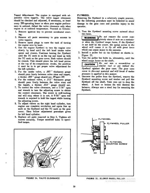
2. Install a puller bar on the flywheel as shown in<br />
Figure 25.<br />
3. Turn the puller bar bolts in, alternately, until the<br />
wheel snaus loose on the shaft.<br />
Do not use a screwdriver or<br />
similar, tool or pry behind the<br />
flywheel against the gear case. The gear case<br />
cover is die-cast maferid <strong>and</strong> will break if undue<br />
pressure is applied in this manner.<br />
4. Unscrew the puller from the flywheel, remove the<br />
flywheel mounting screw <strong>and</strong> washer <strong>and</strong> pull the<br />
flywheel off the shaft. Take care not to drop the<br />
wheel. A bent or broken fin will destroy the<br />
balance. Always use a steel key for mounting the<br />
flywheel.<br />
F E E W H E E L PULLER<br />
FLYWHEEL<br />
UNTING SCREW<br />
FIGURE 24. VALVE CLEARANCE<br />
FIGURE 25. BLOWER WHEEL PULLEY<br />
19


