

Service and Parts Manual - Cummins Onan
Service and Parts Manual - Cummins Onan
Service and Parts Manual - Cummins Onan

Create successful ePaper yourself
Turn your PDF publications into a flip-book with our unique Google optimized e-Paper software.
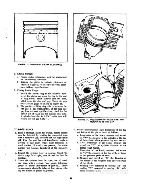
FIGURE 33. MEASURING PISTON CLEARANCE<br />
1. Fitting Pistons:<br />
a. Proper piston tolerances must. be maintained<br />
for satisfactory operation.<br />
b. Measure the piston to cylinder clearance as<br />
shown in Figure 33 to be sure the total clearance<br />
follows specifications.<br />
2. Fitting Piston Rings:<br />
a. Install the piston ring in the cylinder bore.<br />
Invert the piston <strong>and</strong> push the ring to the end<br />
of ring travel, about halfway into the bore,<br />
which trues the ring end gap. Check the gap<br />
with a feeler gauge as shown in Figure 34.<br />
b. The practice of filing ring ends to increase the<br />
end gap is not recommended. If the ring end<br />
gap does not meet specifications, check for the<br />
correct set of rings <strong>and</strong> the carrect bore size.<br />
A cylinder bore that is 0.001 ” under size will<br />
reduce the end gap 0.003 ” .<br />
FIGURE 34. POSITIONING OF PISTON RING AND<br />
MEASURING OF END GAP<br />
L<br />
I<br />
CYLINDER BLOCK<br />
1. Make a thorough check for cracks. Minute cracks<br />
may be detected by ccating the suspected area<br />
with a mixture of 25% kerasene <strong>and</strong> 75% light motor<br />
oil. Wipe the part dry <strong>and</strong> immediately apply a<br />
coating of zinc oxide (white lead) dissolved in<br />
wood alcohol. If cracks are present, the white<br />
coating will become discolored at the defective<br />
area.<br />
2. Inspect the cylinder bore far scaring. Check the<br />
Welsh plugs for a tight, even fit <strong>and</strong> the fins for<br />
breakage.<br />
3. Check the cylinder bore for taper, out of round<br />
<strong>and</strong> wear, with’a cylinder bore gauge, telescope<br />
gauge or inside micrometer (Figure 35). These<br />
measurements should be taken at four pIaces - the<br />
top <strong>and</strong> bottom of piston ring travel.<br />
4. Record measurements taken lengthwise at the top<br />
<strong>and</strong> bottom of ‘the piston travel as follows:<br />
a. Lengthwise of the black, measure <strong>and</strong> record<br />
as “A” the diameter of the cylinder at the top<br />
of the cylinder where greatest ring wear occurs.<br />
b. Also, lengthwise of the blak, measure <strong>and</strong><br />
record as “By’ the cylinder diameter at the<br />
piston skirt travel.<br />
c. Crosswise of the block, measure <strong>and</strong> record<br />
as “C” the diameter of the top of the cylinder<br />
at the greatest point of wear.<br />
d.’Measure <strong>and</strong> recard as “D” the diameter at<br />
the bottom of the cylinder bore <strong>and</strong> crosswise<br />
of the block.<br />
e. Reading “A” compared to reading “B” <strong>and</strong><br />
reading “C” compared to reading “D’? indicates<br />
cylinder taper.


