7 Day Timer with Diagnostics Espar - T3-Infos
7 Day Timer with Diagnostics Espar - T3-Infos
7 Day Timer with Diagnostics Espar - T3-Infos

You also want an ePaper? Increase the reach of your titles
YUMPU automatically turns print PDFs into web optimized ePapers that Google loves.
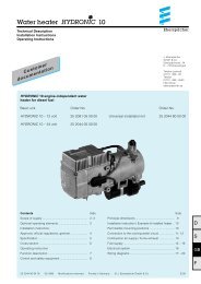
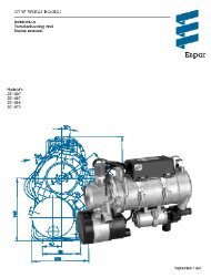
7 <strong>Day</strong> <strong>Timer</strong> <strong>with</strong> <strong>Diagnostics</strong><br />
Installation & Operating Instructions<br />
<strong>Timer</strong> only<br />
P/N 22 1000 30 36 00 (coolant heater 12/24 volt)<br />
P/N 22 1000 30 40 00 (air heater 12/24 volt)<br />
<strong>Espar</strong><br />
<strong>Espar</strong> Products, Inc.<br />
6435 Kestrel Road<br />
Mississauga, Ontario<br />
Canada L5T 1Z8<br />
<strong>Timer</strong>s <strong>with</strong> relays<br />
P/N CA1 00 135 (coolant heater 12V)<br />
P/N CA1 00 136 (coolant heater 24V)<br />
P/N CA1 00 137 (air heater 12V)<br />
P/N CA1 00 138 (air heater 24V)<br />
17672 Laurel Park Drive North<br />
Suite 400E<br />
Livonia, Michigan<br />
United States<br />
48152-3984<br />
Canada (Tel): 905-670-0960<br />
800-668-5676<br />
Fax: 905-670-0728<br />
U.S. (Tel): 800-387-4800<br />
www.espar.com<br />
inquiries@espar.com<br />
Member of Eberspächer GmbH Group of Companies<br />
P/N 603-104-0898<br />
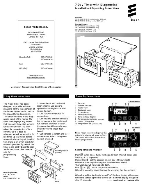
7 <strong>Day</strong> <strong>Timer</strong> Instructions<br />
Operating Instructions<br />
The 7 <strong>Day</strong> <strong>Timer</strong> has been<br />
designed to provide a simple<br />
means to control the operation of<br />
the heater system and to include<br />
the capability for diagnostics.<br />
This timer connects to the diagnostic<br />
circuit of the heater. The<br />
timer then displays any heater<br />
fault codes in three digit number<br />
form automatically. The timer<br />
allows for pre-selection of turn<br />
on time, up to 7 days in<br />
advance, as well as an option for<br />
run times up to 2 hours before<br />
automatically turning off. In addition,<br />
there is an on/off switch for<br />
manual operation. By default the<br />
timer is pre-set by <strong>Espar</strong> to operate<br />
for two hours. See reverse<br />
side for<br />
programming<br />
timer.<br />
Mounting Bracket<br />
P/N CA0 10 061<br />
Bezel<br />
P/N 25 1482 70 01 00<br />
1 Mount bezel into dash and<br />
insert timer or use <strong>Espar</strong>’s<br />
optional mounting bracket and<br />
secure to dash.<br />
2 Use hardware supplied for<br />
connections.<br />
3 Connect the switch harness to<br />
the connector at the heater and<br />
run harness to switch location.<br />
(Harness should be neatly routed<br />
and secured under dashboard).<br />
4 Cut harness to length and terminate<br />
wires. Attach using connectors<br />
provided.<br />
Mounting Bracket<br />
(optional)<br />
Bezel<br />
1 Time set<br />
2 Preheat time set<br />
3 Heater “On”<br />
4 Backward scan<br />
5 Forward scan<br />
6 Memory location<br />
7 Time and day display<br />
8 Air temperature display (optional)<br />
9 Heater “On”symbol<br />
10 Temperature set (air heater only)<br />
Note: Upon connection to power the<br />
entire timer display will begin to flash.<br />
The heater will not function until the<br />
time is programmed.<br />
Setting Time and Weekday<br />
Coolant Heater<br />
Air Heater<br />
Push button once. 12:00 will begin to flash (this will occur upon<br />
initial hook up to power).<br />
Using or set the present time of day (24 hour clock).<br />
When the time stops flashing the time has been stored.<br />
The weekday will now begin to flash.<br />
Use or to set the present weekday.<br />
When the weekday stops flashing the weekday has been stored<br />
.<br />
When the vehicle ignition is turned “on” the time display will appear.<br />
When the vehicle ignition is turned “off” the timer display will go off<br />
after 15 seconds.<br />
......... continued on reverse side
Operating Instructions<br />
Changing the Time or <strong>Day</strong><br />
Push and hold button until the time display begins to flash.<br />
Continue to set the time as listed in setting time and weekday.<br />
Using the <strong>Timer</strong> <strong>with</strong> the Vehicle Ignition “Off”<br />
Push button.<br />
will appear on the display as well as the operation countdown timer.<br />
The running time is factory set to a maximum of 120 minutes. This<br />
running time can be reset once or permanently as desired.<br />
Adjusting Preheat Time Once<br />
To Use Preset Start Times<br />
Press the button until the desired memory location<br />
appears in the display.<br />
The heater will start at the day and time displayed.<br />
The display will go off in 15 seconds. The memory location<br />
number will stay displayed (1, 2 or 3).<br />
To Turn Heater “Off” - All Modes<br />
Press the button once.<br />
The heat signal to the heater will be turned “off”.<br />
The heater will do a normal cooldown and turn itself “off”.<br />
<strong>Espar</strong><br />
Press button.<br />
The will appear in the display and the preselected run time will<br />
appear in the display (maximum time of 120 minutes).<br />
Use the or to adjust the desired run time.<br />
Adjusting the Heater Preheat Time Permanently<br />
(Maximum Preheat Time of 120 minutes)<br />
Push and hold (about 3 seconds) until the display lights up and<br />
flashes. Release button.<br />
Use or to set the new fixed preheat time.<br />
When the display goes off the new preheat time is set.<br />
Note: At the end of a preheat cycle the timer will turn the heater off.<br />
The heater will complete a cool down cycle and turn itself off.<br />
Using the Heater Manually <strong>with</strong> the Vehicle Accessory “On”<br />
Push button.<br />
The symbol will appear in the display next to the time of day.<br />
The time of day will remain displayed during ignition on operation.<br />
The heater will function continually as long as the vehicle ignition is “ o n ”.<br />
When the vehicle ignition is turned “off” the heater will continue to<br />
operate for an addtional 15 minutes.<br />
The run time can be altered by pressing the or buttons.<br />
The heater can be turned off by pressing button.<br />
Set Preheat Times into Memory<br />
Press button until the desired memory location is shown in the<br />
display (Three memory locations are available).<br />
Using the or buttons set the desired preheat start time of day.<br />
When the time stops flashing the time of day is set.<br />
Using the or buttons set the desired day of the week.<br />
When the day of the week stops flashing the day is set.<br />
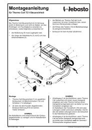
Coolant Heater <strong>Timer</strong> Connections<br />
Note: When the vehicle ignition is turned “on” the time of day and day of the<br />
week will appear in the timer display. This will stay on as long as the vehicle<br />
ignition is “on”.<br />
Note: When the vehicle lights are turned “on” the timer backlight will come<br />
“on”also.<br />
Note: This timer is equipped to display fault code numbers if the heater<br />
should shut down due to an operating fault.The fault code will show in the<br />
timer display next to the flashing heat wave symbol.This applies whenever<br />
the timer is used in conjunction <strong>with</strong> the Hydronic heaters, the D7W model 25<br />
1807, the D9W and the D12W models 25 1859 and 25 1860, and has the<br />
blue diagnostic wire connected.<br />
Note: If the timer is purchased <strong>with</strong>out the harness kit, ensure a load relay<br />
is installed for heaters where the switch wire carries a load (i.e. fuel metering<br />
pump or solenoid valve). This affects the current models for D8LC, D7W,<br />
D12W, D24W and D30W heaters.<br />
Note:<br />
An outside temperature sensor is available as an option<br />
Wiring Connections at connector<br />
Terminal 1 Power from vehicle dash lights<br />
Terminal 2 Heater switch wire - yellow wire<br />
Terminal 4 Connect to vehicle ground<br />
Terminal 6 Temperature setting “+” (air only)<br />
Terminal 8 Heater diagnostic lead - blue wire<br />
Terminal 9 Temperature setting “-” (air only)<br />
Terminal 10 To vehicle “ACC”accessory for continuous overnight use<br />
Terminal 11 Positive power from heater - red “+”<br />
Terminal 12 Ground lead from heater - brown “-”<br />
Terminal 3,5,7 Left blank, not required<br />
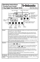
Air Heater <strong>Timer</strong> Connectionsa<br />
a) Power from battery”+”<br />
b) Switch control to heater<br />
c) Power from battery”-”<br />
d) <strong>Diagnostics</strong> from heater<br />
e) To vehicle dimmer switch for light display<br />
f) To vehicle ignition accessories for continuous<br />
operation of heater<br />
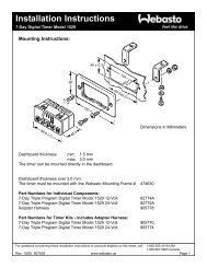
a) Power from battery ”+”<br />
b) Switch control to heater<br />
c) Power from battery ”-”<br />
d) <strong>Diagnostics</strong> from heater<br />
e) Temperature setting “+”<br />
f) Temperature setting “-”<br />
g) To vehicle dimmer switch for light display<br />
h) To vehicle ignition accessories for continuous operation of heater