LS-800 Series Part Numbers - Pressure Switch Instruments - Gems ...
LS-800 Series Part Numbers - Pressure Switch Instruments - Gems ...
LS-800 Series Part Numbers - Pressure Switch Instruments - Gems ...

Create successful ePaper yourself
Turn your PDF publications into a flip-book with our unique Google optimized e-Paper software.
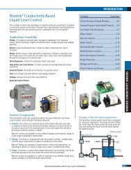
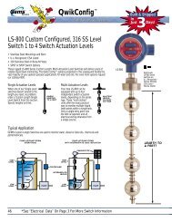
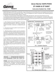
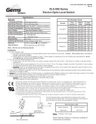
Integrated Temperature Sensors Options<br />
1. Thermistor for Continuous Indication<br />
• Excellent Repeatability<br />
Value: 10,000 ohms @ 77°F (25°C)<br />
Tolerance: ±0.2°C from 32°F to 158°F (0°C to 70°C)<br />
Operating Temperature: 302°F (150°C), Max.<br />
Alpha @ 25°C: -4.39%/°C<br />
Dissipation Constant: 1mW/°C in Still Air<br />
8 mW/°C in Oil Bath<br />
2. Thermostat for <strong>Switch</strong> Action<br />
• Settings from 150°F to 175°F<br />
• Open or close switch on increasing temperature<br />
Note<br />
Contact <strong>Gems</strong> Sensors for Additional Information.<br />
Temperature<br />
Sensor<br />
Assembly<br />
Bottom of Unit<br />
Note<br />
End of unit stem must be submerged a<br />
minimum of 2-3/4” for level switch<br />
actuation.<br />
Typical Wiring Diagram<br />
Instruction Bulletin No. 72978 (Rev P)<br />
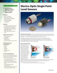
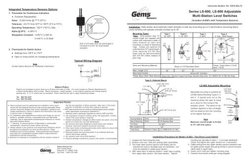
<strong>Series</strong> <strong>LS</strong>-<strong>800</strong>, <strong>LS</strong>-<strong>800</strong> Adjustable<br />
Multi-Station Level <strong>Switch</strong>es<br />
(Includes <strong>LS</strong>-<strong>800</strong>’s with Temperature Sensors)<br />
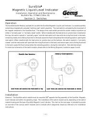
Installation Multi-station level switches install vertically in tank top (mounting up) or in tank bottom (mounting down).<br />
Level switches will operate normally inclined up to 30°.<br />
Mounting Types<br />
*Note: Units greater than 72”<br />
overall length are supplied with<br />
collars with setscrews (made of<br />
same material as stem and<br />
mounting), in place of float-stop<br />
rings. Collars are optional on<br />
units less than 72” overall length.<br />
Units requiring 316 SS float<br />
stops must be special-ordered<br />
with 316 SS collars instead of<br />
grip rings.<br />
Stem and Mounting Material<br />
Max. Length (LO)<br />
Mounting Position<br />
*Float Stops (See *Note Above)<br />
Type 1<br />
1/2” NPT<br />
1/2”<br />
NPT<br />
Type 5 - External Mount<br />
Type 2<br />
1-1/4” NPT<br />
<br />
<br />
1/2”<br />
NPT<br />
1” SQ.<br />
1-1/4”<br />
NPT<br />
<br />
Type 3<br />
2” NPT<br />
1/2”<br />
NPT<br />
1-1/4” SQ.<br />
2”<br />
NPT<br />
Type 4<br />
3” Dia., 150# Flangeype<br />
6” Bolt<br />
Circle<br />
7-1/2” Dia. <br />
3/4”<br />
Dia.<br />
Brass or 316 Stainless Steel<br />
Flange: Carbon Steel or 316 SS<br />
Stem: 316 SS<br />
36” 60”<br />
140”<br />
Vertical ±30° Inclination<br />
Brass Units: Beryllium Copper Grip Rings; Stainless Steel Units: S.S. ARMCO PH-15-7MO Grip Rings<br />
<br />
<br />
1/2”<br />
NPT<br />
<br />
<br />
1”<br />
Return Policy<br />
Returns are accepted on stock items up to 30 days from date of order. You must contact our Returns Department for<br />
a Return Authorization (RA) number. Return the goods - freight prepaid - in the original container and include original<br />
packing slip. C. O. D. returns are not accepted. <strong>Gems</strong> reserves the right to apply restocking charges.<br />
Tel: 860-793-4357<br />
Fax: 860-793-4563<br />
• <strong>Gems</strong> products must be maintained and installed in strict accordance<br />
with the National Electrical Code and the applicable <strong>Gems</strong><br />
product instruction Bulletin that covers installation, operation and<br />
proper maintenance. Failure to observe this information may result<br />
in serious injury or damages.<br />
• For hazardous area applications involving such things as, but not<br />
limited to, ignitable mixtures, combustible dust and flammable<br />
materials, use an appropriate explosionproof enclosure or intrinsically<br />
safe interface device.<br />
• *** Warning: To prevent ignition of flammable or combustible<br />
atmospheres, disconnect power before servicing.<br />
• Please adhere to the pressure and temperature limitations shown<br />
throughout this catalog for our level and flow sensors. These<br />
limitations must not be exceeded. These pressures and temperatures<br />
take into consideration possible system surge pressures/<br />
temperatures and their frequencies.<br />
• Selection of materials for compatibility with the media is critical to<br />
Important Points:<br />
the life and operation of <strong>Gems</strong> products. Take care in the proper<br />
selection of materials of construction, testing is required.<br />
• NSF-approved sensors are made of materials approved for potable<br />
water applications according to Standard 61.<br />
• Stainless steel is generally regarded as safe by NSF and FDA.<br />
• Life expectancy of switch contacts varies with application. Contact<br />
<strong>Gems</strong> if life cycle testing is required.<br />
• Ambient temperature changes do affect switch set points, since the<br />
gravity of a liquid can vary with temperature.<br />
• Our sensors have been designed to resist shock and vibration.<br />
However, shock and vibration should be minimized.<br />
• Filter liquid media containing particulate and/or debris to ensure the<br />
proper operation of our products.<br />
• Electrical entries and mounting points in an enclosed tank may<br />
require liquid/vapor sealing.<br />
• Our sensors must not be field-repaired.<br />
• Physical damage sustained by product may render it unserviceable.<br />
<strong>Gems</strong> Sensors Inc.<br />
One Cowles Road<br />
Plainville, CT 06062-1198<br />
Toll-Free: 1-<strong>800</strong>-378-1600<br />
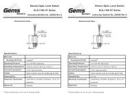
Unit Length<br />
L O<br />
+2”<br />
Housing Material<br />
Stem & Mounting<br />
Port Sizes<br />
Max. Length (LO)<br />
*Float Stops<br />
2-5/8” (66.7mm)<br />
1/2” FNPT<br />
Dia. Ref.<br />
O-Ring 2-1/4”-12<br />
UNF-2A Thread<br />
L O<br />
± 1/6”<br />
<br />
2” (50.8mm)<br />
<br />
Brass<br />
Brass<br />
Beryllium Copper<br />
<br />
1-3/4” (44.5mm)<br />
<br />
3/4” NPT Ports (2X)<br />
316 Stainless Steel<br />
316 Stainless Steel<br />
3/4” NPT<br />
120”<br />
S. S. ARMCO PH-15-7 MO<br />
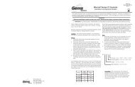
1. Unpack unit from shipping crate.<br />
2. Position unit near tank and unstrap stem assemblies.<br />
3. The lower stem section (section with floats) can be<br />
inserted into tank to facilitate ease of installation, but<br />
must be retained to install upper section.<br />
4. With lower stem in desired position, insert tube coupling<br />
from upper stem section into lower section. Tighten<br />
<strong>LS</strong>-<strong>800</strong> Adjustable Mounting<br />
Adjustable mounting is available for<br />
<strong>LS</strong>-<strong>800</strong> <strong>Series</strong> Mounting Types 2, 3,<br />
and 4. A special cinch nut on the<br />
mounting allows the stem to travel<br />
up or down for fine tuning of the<br />
actuation points. The extent of adjustment<br />
depends on the unit length<br />
and the distance from the mounting<br />
to the highest float stop.<br />
Note<br />
Maximum overall length is limited<br />
to 72” with this option.<br />
Installation Procedure for Model <strong>LS</strong>-802 - Two-Piece Level <strong>Switch</strong><br />
Unit Stem<br />
Adjusted<br />
Upward<br />
Union<br />
Mounting<br />
<br />
Max<br />
Adjust<br />
<br />
Float<br />
Stop<br />
coupling nut securely to stem (~ 1 turn past handtight).<br />
Check and tighten the upper section nut, if necessary.<br />
5. Cable exiting from the upper section conduit connector can<br />
be lightly pulled taught through grommet to prevent excess<br />
cable slack in upper stem.<br />
6. Install unit in tank and tighten mounting plug.<br />
7. Connect level switch wires per wiring diagram.
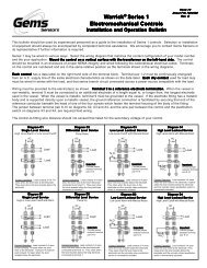
Electrical Specifications<br />
<strong>Switch</strong> Ratings - Maximum Resistive Load<br />
Float Types<br />
<strong>Switch</strong> (N.O. or N.C.):<br />
VA<br />
Volts<br />
Amps AC<br />
Amps DC<br />
Float Material<br />
Compatible Mounting Types<br />
Buna N<br />
316 Stainless Steel<br />
2 1, 3, 4, 5 1, 3, 4, 5 (Units 72”)<br />
SPST: 20 VA or 100 VA<br />
SPDT: 20 VA<br />
Lead Wires: #22 AWG, 24” L., Polymeric<br />
10<br />
General Use<br />
0-50<br />
120<br />
100<br />
.2<br />
.08<br />
N.A.<br />
.13<br />
N.A.<br />
.1<br />
Float Dimensions<br />
<strong>Part</strong> Number<br />
1-3/4”<br />
(44.5mm)<br />
1-1/4” Dia.<br />
(31.8mm)<br />
1-13/16”<br />
(46.0mm)<br />
1-7/8” Dia.<br />
(47.6mm)<br />
2”<br />
(50.8mm)2-3/32”<br />
(53.3mm)<br />
2-1/16”<br />
(52.4mm)<br />
26032 10558 14569 15666<br />
2-11/16”<br />
(68.3mm)<br />
2-1/16” Dia.<br />
(52.4mm)<br />
Typical Wiring Diagrams<br />
For clarity, only two actuation levels are shown in<br />
each group diagram.<br />
Group I<br />
SPST<br />
Group II<br />
SPST<br />
20<br />
Pilot Duty<br />
50<br />
General Use<br />
1-30<br />
120<br />
240<br />
0-50<br />
120<br />
240<br />
.4<br />
.17<br />
.08<br />
0.5<br />
.4<br />
.2<br />
.3<br />
.13<br />
.06<br />
0.5<br />
.4<br />
.2<br />
Operating Temperature<br />
Min. Media Specific Gravity<br />
Water: To 180°F (82.2°C)<br />
-40°F to +300°F (-40°C to +148.9°C)<br />
Oil: -40°F to +230°F (-40°C to 110°C)<br />
.75 .55 .75 .75<br />
Group III<br />
SPDT<br />
Group IV<br />
SPDT<br />
100*<br />
120<br />
240<br />
.8**<br />
.4<br />
N.A.<br />
N.A.<br />
* Level switch units with 50 VA and 100 VA swtiches are<br />
not UL recognized or CSA approved.<br />
** Limited to 50,000 operations<br />
<strong>Pressure</strong> Ratings Chart<br />
(PSI, Max.)<br />
Mounting<br />
Type<br />
Wiring Color Codes<br />
Wiring<br />
Com. Wire<br />
L1<br />
L2<br />
L3<br />
L4<br />
L5<br />
L6<br />
5<br />
1, 2, 3<br />
4<br />
Brass<br />
316 S.S.<br />
Float <strong>Part</strong> Number<br />
26032 10558 14569 15666<br />
150 750 300<br />
150<br />
100 @ +70°F (21.1°C)<br />
150 750 300<br />
SPST <strong>Switch</strong>es<br />
SPDT <strong>Switch</strong>es 20 VA<br />
Group I<br />
Black<br />
Group II<br />
None<br />
Group III<br />
Black<br />
Group IV<br />
None<br />
NO/NC<br />
Red<br />
Yellow<br />
Blue<br />
Brown<br />
Orange<br />
Gray<br />
Sw. Com.<br />
Red<br />
Yellow<br />
Blue<br />
Brown<br />
Orange<br />
Gray<br />
NO/NC<br />
Red<br />
Yellow<br />
Blue<br />
Brown<br />
Orange<br />
Gray<br />
NO<br />
Red<br />
Yellow<br />
Blue<br />
Brown<br />
Orange<br />
Gray<br />
NC<br />
Wh/Red<br />
Wh/Yel<br />
Wh/Blu<br />
Wh/Brn<br />
Wh/Orn<br />
Wh/Gray<br />
Sw. Com.<br />
Red<br />
Yellow<br />
Blue<br />
Brown<br />
Orange<br />
Gray<br />
NO<br />
Wh/Red<br />
Wh/Yel<br />
Wh/Blu<br />
Wh/Brn<br />
Wh/Orn<br />
Wh/Gray<br />
NC<br />
Wh/Blk/Red<br />
Wh/Blk/Yel<br />
Wh/Blk/Blu<br />
Wh/Blk/Brn<br />
Wh/Blk/Orn<br />
Wh/Blk/Gra<br />
Notes:<br />
1. Multi-station units included in shaded areas of chart can be supplied in UL-recognized configurations.<br />
2. Wire size is #18 AWG for units of UL-recognized configurations and #22 AWG (Teflon) for<br />
non-UL- recognized configurations.<br />
3. Units with 50 or 100 VA switches are not UL-recognized.<br />
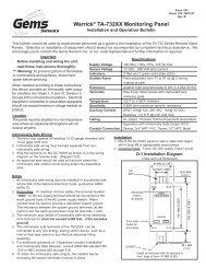
Actuation Level Dimensions<br />
L1<br />
L2<br />
L3<br />
L4<br />
L5<br />
L6<br />
L O<br />
(Length<br />
Overall)<br />
*Actuation level distances and L O<br />
(overall unit length) are<br />
measured from inner surfaces of mounting plug or flange.<br />
** Length Overall L O<br />
= L 1<br />
+ Dimension B. See mounting types for<br />
maximum length values.<br />
A<br />
D<br />
C<br />
B<br />
<strong>Switch</strong> actuation levels are determined following the<br />
guidelines below:<br />
All units 72" or less length overall with stainless steel or<br />
Buna N floats. Also Type 5 units over 72" length overall with<br />
Buna N floats:<br />
A = 1-1/2" minimum distance to highest level (2", Type 5 only)<br />
B = 2" minimum distance from end of unit to lowest level<br />
C = 3" minimum distance between levels<br />
D = 1/4" minimum distance between actuation levels (Note: One<br />
float for two levels can be used only when low level is N.C. dry<br />
and high level is N.O. dry.)<br />
Types 1, 3, 4 and 5 units with stainless steel float P/N 15666:<br />
A = 1-5/8" minimum distance to highest level (2", Type 5 only)<br />
B = 2-1/2" minimum distance from end of unit to lowest level<br />
C = 4" minimum distance between levels<br />
D = 1/4" minimum distance between actuation levels (Note: One float<br />
for two levels can be used only when low level is N.C. dry and<br />
high level is N.O. dry.)<br />
Notes:<br />
1. A, B, and C dimensions are based on liquid specific gravity of 1.0.<br />
2. One float for two levels can be used only when 20VA switch is<br />
used.<br />
3. Actuation levels are calibrated on descending fluid level, with<br />
water as types for maximum length values. the calibrating fluid,<br />
unless otherwise specified.<br />
4. Tolerance on actuation levels is ±1/8".