Medium Voltage Application Guide
Medium Voltage Application Guide
Medium Voltage Application Guide

Create successful ePaper yourself
Turn your PDF publications into a flip-book with our unique Google optimized e-Paper software.
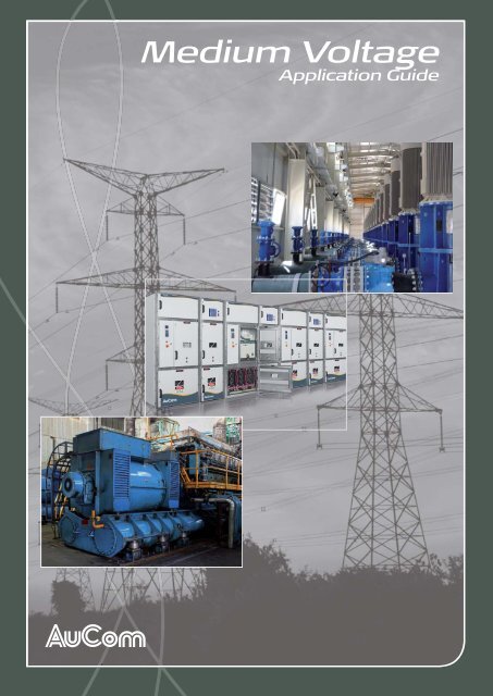
<strong>Medium</strong> <strong>Voltage</strong><br />
<strong>Application</strong> <strong>Guide</strong>
CONTENTS<br />
Contents<br />
1 Introduction ........................................................................................................................................................................... 4<br />
2 Motors ...................................................................................................................................................................................... 5<br />
2.1 Common types of industrial motors .................................................................................................................................................. 5<br />
Induction motors........................................................................................................................................................................................... 5<br />
Useful formulae .............................................................................................................................................................................................. 6<br />
Slip-ring motors ............................................................................................................................................................................................. 7<br />
Synchronous motors ................................................................................................................................................................................... 9<br />
2.2 Motor starting methods ......................................................................................................................................................................... 10<br />
Direct on-line starting .............................................................................................................................................................................. 10<br />
Primary resistance starting..................................................................................................................................................................... 11<br />
Auto-transformer starting ..................................................................................................................................................................... 13<br />
Star-Delta starting ...................................................................................................................................................................................... 15<br />
Soft starters ................................................................................................................................................................................................... 16<br />
Variable frequency drives (VFD) ....................................................................................................................................................... 17<br />
3 Soft Starters ........................................................................................................................................................................ 19<br />
3.1 What is a Soft Starter .............................................................................................................................................................................. 19<br />
Open loop soft start control ............................................................................................................................................................... 20<br />
Closed loop soft start control............................................................................................................................................................. 21<br />
3.2 Benefits ............................................................................................................................................................................................................ 22<br />
Electrical Benefits ....................................................................................................................................................................................... 22<br />
Mechanical Benefits ................................................................................................................................................................................... 22<br />
<strong>Application</strong> Benefits .................................................................................................................................................................................. 22<br />
3.3 Anatomy ......................................................................................................................................................................................................... 23<br />
Key components ........................................................................................................................................................................................ 23<br />
SCRs.................................................................................................................................................................................................................. 23<br />
Snubber circuits .......................................................................................................................................................................................... 24<br />
Heatsinks ........................................................................................................................................................................................................ 24<br />
Fans .................................................................................................................................................................................................................... 25<br />
Busbars ............................................................................................................................................................................................................ 25<br />
Current sensors .......................................................................................................................................................................................... 25<br />
PCBs.................................................................................................................................................................................................................. 25<br />
Housing ........................................................................................................................................................................................................... 25<br />
Common functionality and features ................................................................................................................................................ 26<br />
3.4 AuCom <strong>Medium</strong> <strong>Voltage</strong> Soft Starters .......................................................................................................................................... 29<br />
MVS Soft Starter ........................................................................................................................................................................................ 29<br />
MVX Soft Starter ....................................................................................................................................................................................... 34<br />
Soft starter communication options ................................................................................................................................................ 40<br />
Predictive Maintenance Module (PMM) ........................................................................................................................................ 42<br />
3.5 Selection <strong>Guide</strong>lines ................................................................................................................................................................................. 43<br />
Considerations ............................................................................................................................................................................................ 43<br />
Switchgear Requirements ...................................................................................................................................................................... 45<br />
AC53 Utilisation Codes ......................................................................................................................................................................... 52<br />
3.6 Calculations ................................................................................................................................................................................................... 54<br />
What is the minimum start current with a soft starter? ....................................................................................................... 54<br />
Calculating required start current for new or existing AC induction motor installations .................................. 54<br />
3.7 Special <strong>Application</strong>s .................................................................................................................................................................................. 59<br />
Forward/Reverse motor starting ....................................................................................................................................................... 59<br />
Multi-motor starting ................................................................................................................................................................................. 61<br />
AuCom multi-motor starting solution ............................................................................................................................................ 64<br />
Slip ring motor control ........................................................................................................................................................................... 66<br />
3.8 Common standards for MV soft starters and switchgear panels ..................................................................................... 68<br />
710-12280-00A <strong>Medium</strong> <strong>Voltage</strong> <strong>Application</strong> <strong>Guide</strong> Page 1
CONTENTS<br />
4 Switchgear ............................................................................................................................................................................ 69<br />
4.1 Switchgear Classifications ...................................................................................................................................................................... 70<br />
IEC Switchgear Classification ............................................................................................................................................................... 71<br />
ANSI-defined switchgear ....................................................................................................................................................................... 72<br />
Switchgear Ratings ..................................................................................................................................................................................... 72<br />
Switchgear information for enquiries or ordering .................................................................................................................... 72<br />
Switchgear derating .................................................................................................................................................................................. 73<br />
4.2 Standard Enclosure Configurations .................................................................................................................................................. 74<br />
Incomer Feeder Panel (IFP) .................................................................................................................................................................. 74<br />
Direct Incomer Panel (DIP) ................................................................................................................................................................. 75<br />
Bus Coupler Panel (BCP) ...................................................................................................................................................................... 76<br />
Bus Riser Panel (BRP) .............................................................................................................................................................................. 77<br />
Metering Panel (MTP) ............................................................................................................................................................................. 78<br />
Busbar Systems ........................................................................................................................................................................................... 79<br />
4.3 Safety Considerations .............................................................................................................................................................................. 83<br />
Switchgear interlocking systems ......................................................................................................................................................... 83<br />
Internal arc classification ......................................................................................................................................................................... 85<br />
4.4 Switchgear Apparatus .............................................................................................................................................................................. 88<br />
<strong>Medium</strong> <strong>Voltage</strong> Circuit Breakers ..................................................................................................................................................... 88<br />
<strong>Medium</strong> <strong>Voltage</strong> Contactors ............................................................................................................................................................... 96<br />
<strong>Medium</strong> <strong>Voltage</strong> Switches .................................................................................................................................................................. 100<br />
<strong>Medium</strong> <strong>Voltage</strong> HRC Fuses ............................................................................................................................................................ 104<br />
Current Transformers .......................................................................................................................................................................... 110<br />
Current Sensors ...................................................................................................................................................................................... 119<br />
Protection Devices ................................................................................................................................................................................. 121<br />
<strong>Voltage</strong> Transformers ........................................................................................................................................................................... 127<br />
Motor Line Inductors on Soft Starter <strong>Application</strong>s .............................................................................................................. 130<br />
<strong>Medium</strong> <strong>Voltage</strong> Surge Arrestors .................................................................................................................................................. 132<br />
Power Factor Capacitors .................................................................................................................................................................... 136<br />
4.5 Calculations ................................................................................................................................................................................................ 143<br />
Transformer Calculations ................................................................................................................................................................... 143<br />
Motor Calculations ................................................................................................................................................................................. 147<br />
Busbar Calculations ................................................................................................................................................................................ 149<br />
Short Circuit Calculations ................................................................................................................................................................... 156<br />
Impedance Method Calculations .................................................................................................................................................... 159<br />
4.6 Switchgear Inspection Checklists .................................................................................................................................................... 162<br />
Mechanical Inspection .......................................................................................................................................................................... 162<br />
Electrical Inspection ............................................................................................................................................................................... 163<br />
Commissioning Tools and Equipment (Typical) .................................................................................................................... 164<br />
4.7 Switchgear-Related IEC Standards ................................................................................................................................................ 165<br />
4.8 Comparison of IEC and IEEE Standards ..................................................................................................................................... 167<br />
Examples of differences in rating requirements ..................................................................................................................... 167<br />
4.9 IEC Switchgear Rating Definitions.................................................................................................................................................. 168<br />
<strong>Voltage</strong> .......................................................................................................................................................................................................... 168<br />
Current ......................................................................................................................................................................................................... 168<br />
Frequency, fr (Hz) .................................................................................................................................................................................. 169<br />
4.10 Protection index ...................................................................................................................................................................................... 170<br />
IP Ratings ..................................................................................................................................................................................................... 170<br />
NEMA Ratings .......................................................................................................................................................................................... 171<br />
5 Schematic Diagrams ..................................................................................................................................................... 172<br />
5.1 Electrical Symbols - Common Switching Functions ............................................................................................................. 172<br />
5.2 Circuit Breaker Control (Typical) .................................................................................................................................................. 173<br />
5.3 Contactor Control (Typical)............................................................................................................................................................. 174<br />
5.4 Automatic Changeover Systems .................................................................................................................................................... 175<br />
Overview ..................................................................................................................................................................................................... 175<br />
5.5 MVS Schematic Diagrams .................................................................................................................................................................. 178<br />
Page 2 <strong>Medium</strong> <strong>Voltage</strong> <strong>Application</strong> <strong>Guide</strong> 710-12280-00A
CONTENTS<br />
E3 panel option........................................................................................................................................................................................ 178<br />
E2 panel option........................................................................................................................................................................................ 179<br />
5.6 MVX Schematic Diagrams ................................................................................................................................................................. 180<br />
Contactor panel option ....................................................................................................................................................................... 180<br />
Circuit breaker panel option ............................................................................................................................................................ 181<br />
6 Resources .......................................................................................................................................................................... 182<br />
6.1 Equipment Specifications .................................................................................................................................................................... 182<br />
6.2 Metric/Imperial Conversion Factors.............................................................................................................................................. 216<br />
6.3 Wire Diameter Conversion .............................................................................................................................................................. 217<br />
6.4 Incoterms .................................................................................................................................................................................................... 218<br />
6.5 Commonly Used Abbreviations ..................................................................................................................................................... 219<br />
7 References ........................................................................................................................................................................ 221<br />
710-12280-00A <strong>Medium</strong> <strong>Voltage</strong> <strong>Application</strong> <strong>Guide</strong> Page 3
INTRODUCTION<br />
1 Introduction<br />
This reference guide is designed to help engineers in the field of medium voltage select and specify the right MV<br />
equipment for their application.<br />
This guide provides an overview of all the main components in a motor control system, in a format that is readily<br />
understood by people with limited or no experience with motor control in general and soft starters in particular.<br />
We hope this document will help:<br />
consulting engineers wanting to specify motor control equipment<br />
technical departments using motor control equipment<br />
maintenance engineers at locations with soft starters installed<br />
We would welcome your feedback so we can continue to improve this guide.<br />
The examples and diagrams in this manual are included solely for illustrative purposes. The information contained<br />
in this manual is subject to change at any time and without prior notice. In no event will responsibility or liability be<br />
accepted for direct, indirect or consequential damages resulting from the use or application of this equipment.<br />
© 2012 AuCom Electronics Ltd. All Rights Reserved.<br />
As AuCom is continuously improving its products it reserves the right to modify or change the specification of its products at<br />
any time without notice. The text, diagrams, images and any other literary or artistic works appearing in this document are<br />
protected by copyright. Users may copy some of the material for their personal reference but may not copy or use material<br />
for any other purpose without the prior consent of AuCom Electronics Ltd. AuCom endeavours to ensure that the<br />
information contained in this document including images is correct but does not accept any liability for error, omission or<br />
differences with the finished product.<br />
Page 4 <strong>Medium</strong> <strong>Voltage</strong> <strong>Application</strong> <strong>Guide</strong> 710-12280-00A
MOTORS<br />
2 Motors<br />
2.1 Common types of industrial motors<br />
Induction motors<br />
An induction motor performs two primary functions:<br />
start - convert electrical energy into mechanical energy in order to overcome the inertia of the load and<br />
accelerate to full operating speed.<br />
run - convert electrical energy into productive work output to a driven load.<br />
Full voltage starting (also referred to as direct on-line or across-the-line starting) results in a high starting current,<br />
equal to locked rotor current. The locked rotor current (LRC) of a motor depends on the motor design, and is<br />
typically between five and ten times motor full load current (FLC). A value of six times FLC is common. Shaft<br />
loading only affects start time, not LRC.<br />
High motor starting currents can cause voltage fluctuations on the electrical supply system, and electrical supply<br />
authorities often require reduction in motor starting current. Reduced voltage starting of an induction motor<br />
reduces the available starting torque, and loads with demanding start torque requirements may not be compatible<br />
with reduced voltage starting.<br />
When selecting a motor for a specific application, both the start and run characteristics are very important.<br />
Motors consist of two major components:<br />
<br />
<br />
The stator consists of magnetic poles created from stator windings located in slots within the frame of the<br />
motor. The full load running characteristics of the motor are determined by the winding configuration and<br />
the contour of the stator slots and laminations. Motor speed is determined by the number of pole pairs<br />
and the supply frequency applied to the stator windings.<br />
The rotor consists of a cylindrical short circuited winding, embedded within iron laminations. The rotor<br />
winding is often referred to as a squirrel cage. This cage is constructed from a number of bars running<br />
parallel to the motor shaft near the surface of the rotor. The rotor bars are short circuited at each end of<br />
the rotor using shorting rings. The material, position and shape of the rotor bars determines the starting<br />
characteristics of the motor.<br />
The rotor design determines the starting characteristics of the motor. The stator design determines the<br />
running characteristics of the motor.<br />
AC induction motor<br />
When 3-phase supply voltage is applied to the stator winding of an induction motor, a rotating magnetic field is<br />
produced which cuts through the rotor bars. The rotating speed of this magnetic field is referred to as "synchronous<br />
speed".<br />
Interaction between the rotating magnetic field and the rotor bars induces a voltage which causes current to flow in<br />
the rotor bars. This rotor current produces a magnetic field in each rotor bar. Interaction between the stator's<br />
rotating magnetic field and the rotor bar magnetic fields produces a torque which causes the rotor to be driven in<br />
the same rotational direction as the stator magnetic field.<br />
Torque produced by the rotor varies from stationary to full running speed. This torque is primarily a function of the<br />
rotor resistance and leakage reactance. The latter is determined by the difference in rotational speed between stator<br />
710-12280-00A <strong>Medium</strong> <strong>Voltage</strong> <strong>Application</strong> <strong>Guide</strong> Page 5
03340.B<br />
Current<br />
Torque<br />
MOTORS<br />
magnetic field and the rotor, otherwise known as slip. Slip is commonly expressed as a percentage of the motor's<br />
synchronous speed.<br />
Motor start performance characteristics can vary greatly depending on rotor design and construction, but in general,<br />
a motor with high locked rotor current will produce low locked rotor torque and vice versa. A high resistance rotor<br />
produces relatively high starting torque but runs at high slip which causes inefficiency. To produce superior starting<br />
and running characteristics, specially shaped rotor bars or double cage rotors are used.<br />
Typical start performance characteristics of an induction motor.<br />
7 x FLC<br />
6 x FLC<br />
5 x FLC<br />
2 x FLT<br />
Full voltage motor current<br />
Full voltage motor torque<br />
Load torque (quadratic load, eg<br />
pump)<br />
4 x FLC<br />
3 x FLC<br />
1 x FLT<br />
2 x FLC<br />
1 x FLC<br />
10% 20% 30% 40% 50% 60% 70% 80% 90% 100%<br />
Speed<br />
Useful formulae<br />
Motor synchronous speed<br />
Ns = f × 60<br />
p<br />
Motor slip speed (%)<br />
N<br />
slip<br />
(Ns<br />
N r)<br />
= ×100<br />
N<br />
Motor shaft output power<br />
P N r × T r<br />
o =<br />
9550<br />
Motor electrical input power<br />
Pi = 3× V× I × cos<br />
Motor efficiency<br />
Po<br />
eff = × 100<br />
P<br />
i<br />
s<br />
Where:<br />
N s = synchronous speed (rpm)<br />
f = mains supply frequency (Hz)<br />
p = number of stator pole pairs<br />
Where:<br />
N slip = percentage slip speed (%)<br />
N s = synchronous speed (rpm)<br />
= rotor speed (rpm)<br />
N r<br />
Where:<br />
P o = output power (kW)<br />
N r = rotor shaft speed (rpm)<br />
= rotor torque (Nm)<br />
T r<br />
Where:<br />
P i = input power (kW)<br />
V = motor line voltage (kV)<br />
I = motor line current (A)<br />
cosØ = motor power factor<br />
Where:<br />
eff = motor efficiency (%)<br />
P o = motor output power (kW)<br />
= motor input power (kW)<br />
P i<br />
Page 6 <strong>Medium</strong> <strong>Voltage</strong> <strong>Application</strong> <strong>Guide</strong> 710-12280-00A
MOTORS<br />
Slip-ring motors<br />
A slip-ring induction motor is also referred to as a wound rotor motor. In principle, the stator construction is the<br />
same as that of a squirrel cage induction motor. The rotor is made up of a set of windings embedded in rotor slots<br />
and brought out to a set of slip-rings. External rotor resistance is then connected to the slip-rings via a brush gear<br />
arrangement. The external rotor resistance is variable and is used for starting the motor.<br />
Slip-ring rotor arrangement<br />
Slip-ring motor installation<br />
KR2<br />
KR1<br />
3<br />
KM1<br />
R2<br />
R1<br />
1 2<br />
4<br />
A<br />
B<br />
13227.A<br />
Three-phase supply<br />
KM1 Main contactor<br />
Slip-ring motor<br />
Bridging contactors<br />
KR1 First stage contactor<br />
KR2 Second stage contactor<br />
A Stator External rotor resistance<br />
B Rotor R1 First stage resistor bank<br />
R2 Second stage resistor bank<br />
A high level of starting torque is produced by matching the rotor resistance with the rotor leakage reactance as the<br />
motor speed increases. At standstill, all the available external rotor resistance is in the circuit. As the motor speed<br />
increases, the external rotor resistance is reduced by using shorting contactors, until all the external resistance is<br />
shorted out. At this stage, the motor has reached full running speed. Motor start current is limited by the relatively<br />
high impedance of the motor due to the external rotor resistance.<br />
The major advantage of a slip-ring motor is that it produces very high starting torque (150-250% of full<br />
load torque) from standstill to full running speed, while consuming a relatively low level of start current<br />
(200-350% of full load current).<br />
710-12280-00A <strong>Medium</strong> <strong>Voltage</strong> <strong>Application</strong> <strong>Guide</strong> Page 7
Torque<br />
Current<br />
MOTORS<br />
Typical start performance characteristics of a slip-ring motor.<br />
Slip-ring speed control<br />
Speed<br />
In some cases, the variable resistance is used for speed control of the load. This method of speed control can cause<br />
erratic fluctuations in speed (if the load demand changes), and heat loss from the resistors causes major inefficiencies.<br />
Compared with using a slip-ring motor for speed control, a better result can be achieved by using a variable<br />
frequency drive (VFD) to operate a standard squirrel cage motor. A VFD typically provides more precise speed<br />
control, as well as being more efficient, less expensive, and easier to install and maintain.<br />
Provided sufficient start torque is developed with a single stage of rotor resistance, soft starters can be successfully<br />
applied to slip-ring motors.<br />
Refer to Slip ring motor control on page 66 for further details.<br />
13187.A 13188.A<br />
Speed<br />
Page 8 <strong>Medium</strong> <strong>Voltage</strong> <strong>Application</strong> <strong>Guide</strong> 710-12280-00A
MOTORS<br />
Synchronous motors<br />
The construction of a synchronous motor stator is the same as a standard induction motor, although the stator<br />
configuration is such that relatively low operating speeds are common (eg 300-600 rpm).<br />
When 3-phase voltage is applied to the stator windings, a magnetic field is generated which rotates at a synchronous<br />
speed around the stator and rotor. The synchronous speed is determined by the stator construction and frequency<br />
of the supply voltage.<br />
Motor synchronous speed<br />
Where:<br />
N<br />
N s = synchronous speed (rpm)<br />
s = f × 60<br />
p<br />
f = mains supply frequency (Hz)<br />
p = number of stator pole pairs<br />
The rotor design incorporates a squirrel cage winding combined with a DC excitation winding. This allows the motor<br />
to start as a standard squirrel cage induction motor, reaching a running speed of approximately 95% synchronous<br />
speed. At this point, a DC voltage is applied to the excitation winding via a slip-ring and brush arrangement. A fixed<br />
magnetic field is created in the rotor which locks in with the rotating magnetic field of the stator. The motor shaft<br />
now runs at synchronous speed.<br />
Synchronous motor<br />
Fan inside<br />
Excitation rings (x2)<br />
Three phase stator windings<br />
Rotor with poles and excitation windings<br />
Excitation brushes (x2)<br />
As motor shaft load is increased, the operating power factor of the motor is reduced. This power factor can be<br />
improved by increasing the DC excitation level of the rotor. This behaviour allows the AC synchronous motor to<br />
operate very efficiently at a fixed speed, independent of loading.<br />
Soft starters are suitable for this type of application, but an external DC excitation package is required for<br />
synchronous speed control and operation.<br />
710-12280-00A <strong>Medium</strong> <strong>Voltage</strong> <strong>Application</strong> <strong>Guide</strong> Page 9
03340.B<br />
Current<br />
Torque<br />
MOTORS<br />
2.2 Motor starting methods<br />
When an induction motor is connected to a full voltage supply, it draws several times its rated current. As the load<br />
accelerates, the available torque usually drops a little and then rises to a peak while the current remains very high<br />
until the motor approaches full speed.<br />
Direct on-line starting<br />
The simplest form of starter is the direct on-line (DOL) starter, consisting of an isolation contactor and motor<br />
overload protection device. DOL starters are extensively used in some industries, but in many cases full voltage<br />
starting is not permitted by the power authority.<br />
Full voltage starting causes a current transition from zero to locked rotor current (LRC) at the instant of contactor<br />
closure. LRC is typically between five and ten times motor FLC. The fast rising current transient induces a voltage<br />
transient in the supply, and causes a voltage deflection of six to nine times that expected under full load conditions.<br />
Full voltage starting also causes a torque transient from zero to locked rotor torque at the instant of contactor<br />
closure. The instantaneous torque application causes a severe mechanical shock to the motor, drive system and the<br />
machine. The damage resulting from the torque transient is more severe than that due to the maximum torque<br />
amplitude.<br />
Current and torque profile for DOL starting<br />
7 x FLC<br />
6 x FLC<br />
5 x FLC<br />
2 x FLT<br />
Full voltage motor current<br />
Full voltage motor torque<br />
Load torque (quadratic load, eg pump)<br />
4 x FLC<br />
3 x FLC<br />
1 x FLT<br />
2 x FLC<br />
1 x FLC<br />
10% 20% 30% 40% 50% 60% 70% 80% 90% 100%<br />
Speed<br />
DOL starter installation<br />
Main contactor<br />
Overload relay<br />
Page 10 <strong>Medium</strong> <strong>Voltage</strong> <strong>Application</strong> <strong>Guide</strong> 710-12280-00A
09454.A<br />
MOTORS<br />
Primary resistance starting<br />
Primary resistance starters use resistors connected in series with each phase, between the isolation contactor and<br />
the motor, which limit the start current and torque. The resistors may be wound, cast or liquid resistors.<br />
Primary resistance starter<br />
2<br />
Main contactor<br />
Run contactor<br />
Start resistors<br />
Overload relay<br />
M<br />
3~<br />
1<br />
3 4<br />
The motor current is equal to the line current and the starting torque is reduced by the square of the current<br />
reduction ratio. The current reduction depends on the ratio of the motor impedance to the sum of the added<br />
primary resistance and motor impedance.<br />
As the motor accelerates, the stator impedance increases, resulting in increasing stator voltage with speed. Once the<br />
motor reaches full speed, the resistors are bridged by a second contactor to supply full voltage to the motor.<br />
The initial start voltage is determined by the value of the resistors used. If the resistors are too high in value, there will<br />
be insufficient torque to accelerate the motor to full speed, so the step to full voltage will result in a high current and<br />
torque step.<br />
The reduced voltage start time is controlled by a preset timer which must be correctly set for the application. If the<br />
time is too short, the motor will not reach full speed before the resistors are bridged. Excessive start time results in<br />
unnecessary motor and resistor heating.<br />
Several stages of resistance can be used and bridged in steps to control the current and torque more accurately.<br />
This minimises the magnitude of the current and torque steps.<br />
Primary resistance starters dissipate a lot of energy during start due to the high current through, and the high voltage<br />
across the resistors. For extended times or frequent starts, the resistors are physically large and must be well<br />
ventilated.<br />
Primary resistance starters are closed transition starters, so they are not subject to 'reclose' transients.<br />
710-12280-00A <strong>Medium</strong> <strong>Voltage</strong> <strong>Application</strong> <strong>Guide</strong> Page 11
13190.A<br />
Current<br />
Torque<br />
13193.A<br />
Current<br />
Torque<br />
MOTORS<br />
Start performance characteristics of a correctly selected primary resistance starter<br />
7 x FLC<br />
6 x FLC<br />
5 x FLC<br />
4 x FLC<br />
3 x FLC<br />
2 x FLC<br />
2 x FLT<br />
1 x FLT<br />
Full voltage start current<br />
Primary resistance start current<br />
Full voltage torque<br />
Primary resistance torque<br />
Load torque<br />
1 x FLC<br />
10% 20% 30% 40% 50% 60% 70% 80% 90% 100%<br />
Speed<br />
Start performance characteristics of an incorrectly selected primary resistance starter<br />
7 x FLC<br />
6 x FLC<br />
5 x FLC<br />
4 x FLC<br />
3 x FLC<br />
2 x FLC<br />
1 x FLC<br />
2 x FLT<br />
1 x FLT<br />
Full voltage start current<br />
Primary resistance start current<br />
Full voltage torque<br />
Primary resistance torque<br />
Stall point<br />
Current and torque transient<br />
10% 20% 30% 40% 50% 60% 70% 80% 90% 100%<br />
Speed<br />
How does soft start compare to primary resistance starting?<br />
Compared with primary resistance starters, soft starters are more flexible and reliable.<br />
Primary resistance starters offer limited performance because:<br />
Start torque cannot be fine-tuned to match motor and load characteristics.<br />
Current and torque transients occur at each voltage step.<br />
They are large and expensive.<br />
Liquid resistance versions require frequent maintenance.<br />
Start performance changes as the resistance heats up, so multiple or restart situation are not well<br />
controlled.<br />
They cannot accommodate changing load conditions (eg loaded or unloaded starts).<br />
They cannot provide soft stop.<br />
Page 12 <strong>Medium</strong> <strong>Voltage</strong> <strong>Application</strong> <strong>Guide</strong> 710-12280-00A
13195.A<br />
Current<br />
Torque<br />
13194.A<br />
Current<br />
Torque<br />
09455.A<br />
MOTORS<br />
Auto-transformer starting<br />
Auto-transformer starters use an auto-transformer to reduce the voltage during the start period. The transformer<br />
has a range of output voltage taps which can be used to set the start voltage, and the start time is controlled by a<br />
timer.<br />
The motor current is reduced by the start voltage reduction, and further reduced by the transformer action resulting<br />
in a line current less than the actual motor current.<br />
The initial line current is equal to the LRC reduced by the square of the voltage reduction. A motor started on the<br />
fifty percent tap of an auto-transformer will have a line start current of one quarter of LRC and a start torque of one<br />
quarter of LRT. If the start voltage is too low, or the start time is too short, the transition to full voltage will occur<br />
with the motor at less than full speed, resulting in a high current and torque step.<br />
The simplest auto-transformer starters are single step and often control two phases only. More sophisticated<br />
starters may step through two or more voltage steps while accelerating from the initial start tap to full voltage.<br />
Auto-transformer starters are usually rated for infrequent starting duties. Frequent or extended start rated<br />
auto-transformers are large and expensive due to the heating in the transformer.<br />
Auto-transformer starters can be constructed as open transition starters but most commonly the Korndorfer closed<br />
transition configuration is employed to eliminate the 'reclose' transients.<br />
Auto-transformer connection<br />
Run contactor<br />
M<br />
3~<br />
Thermal overload<br />
Start contactor (A)<br />
Auto-transformer<br />
Start contactor (B)<br />
Start performance characteristics of a correctly selected auto-transformer starter<br />
7 x FLC<br />
6 x FLC<br />
5 x FLC<br />
4 x FLC<br />
3 x FLC<br />
2 x FLT<br />
1 x FLT<br />
Full voltage start current<br />
Auto-transformer start current<br />
Full voltage torque<br />
Auto-transformer torque<br />
2 x FLC<br />
Load torque<br />
1 x FLC<br />
10% 20% 30% 40% 50% 60% 70% 80% 90% 100%<br />
Speed<br />
Start performance characteristics of an incorrectly selected auto-transformer starter<br />
7 x FLC<br />
6 x FLC<br />
5 x FLC<br />
4 x FLC<br />
2 x FLT<br />
Full voltage start current<br />
Auto-transformer start current<br />
Full voltage torque<br />
3 x FLC<br />
2 x FLC<br />
1 x FLC<br />
1 x FLT<br />
Auto-transformer torque<br />
Stall point<br />
Current and torque transient<br />
10% 20% 30% 40% 50% 60% 70% 80% 90% 100%<br />
Speed<br />
710-12280-00A <strong>Medium</strong> <strong>Voltage</strong> <strong>Application</strong> <strong>Guide</strong> Page 13
MOTORS<br />
How does soft start compare to auto-transformer starting?<br />
Compared with auto-transformer starters, soft starters are much more flexible and provide a much smoother start.<br />
Auto-transformer starters offer limited performance because:<br />
They offer only limited ability to adjust start torque to accommodate motor and load characteristics.<br />
There are still current and torque transients associated with steps between voltages.<br />
They are large and expensive.<br />
They are especially expensive if high start frequency is required.<br />
They cannot accommodate changing load conditions (eg loaded or unloaded starts).<br />
They cannot provide soft stop.<br />
Page 14 <strong>Medium</strong> <strong>Voltage</strong> <strong>Application</strong> <strong>Guide</strong> 710-12280-00A
Current<br />
13196.A<br />
Torque<br />
09456.A<br />
MOTORS<br />
Star-Delta starting<br />
Star-delta starters are the most common reduced voltage starter used in industry because of their low cost.<br />
The motor is initially connected in star configuration, then after a preset time the motor is disconnected from the<br />
supply and reconnected in delta configuration. The current and torque in the star configuration are one third of the<br />
full voltage current and torque when the motor is connected in delta.<br />
Star/delta starter installation<br />
Main contactor<br />
Thermal overload<br />
Motor (three-phase)<br />
Delta contactor<br />
Star contactor<br />
The star and delta configurations provide fixed levels of current and torque, and cannot be adjusted to suit the<br />
application.<br />
If the star configuration does not provide enough torque to accelerate the load to full speed, a high starting<br />
torque motor such as a double cage motor should be employed.<br />
If the motor does not reach full speed in star, the transition to delta configuration will result in a high current<br />
and torque step, defeating the purpose of reduced voltage starting.<br />
Most star-delta starters are open transition starters so the transition from star to delta results in very high current and<br />
torque transients in addition to the high step magnitudes. Closed transition star-delta starters are rarely used due to<br />
the increased complexity and cost. The closed transition starter reduces the 'reclose' effect but does not improve<br />
the controllability of the start parameters.<br />
Start performance characteristics of a star/delta starter<br />
7 x FLC<br />
1<br />
6<br />
Full voltage start current<br />
6 x FLC<br />
2 x FLT<br />
Star-delta start current<br />
5 x FLC<br />
Full voltage torque<br />
4 x FLC<br />
3 x FLC<br />
2 x FLC<br />
1 x FLC<br />
2<br />
3<br />
4<br />
5<br />
1 x FLT<br />
Star-delta torque<br />
Stall point<br />
Current and torque transient<br />
10% 20% 30% 40% 50% 60% 70% 80% 90% 100%<br />
Speed<br />
How does soft start compare with star/delta starting?<br />
Compared with star/delta starters, soft starters are much more flexible and provide a smooth start with no risk of<br />
transients.<br />
Star/delta starters offer limited performance because:<br />
Start torque cannot be adjusted to accommodate motor and load characteristics.<br />
There is an open transition between star and delta connection that results in damaging torque and current<br />
transients.<br />
They cannot accommodate varying load conditions (eg loaded or unloaded starts).<br />
They cannot provide soft stop.<br />
The main advantages of star/delta starters are:<br />
They may be cheaper than a soft starter.<br />
When used to start an extremely light load, they may limit the start current to a lower level than a soft<br />
starter. However, severe current and torque transients may still occur.<br />
710-12280-00A <strong>Medium</strong> <strong>Voltage</strong> <strong>Application</strong> <strong>Guide</strong> Page 15
MOTORS<br />
Soft starters<br />
Electronic soft starters control the voltage applied to the motor by means of an impedance in series with each phase<br />
connected to the motor. The impedance is provided by AC switches – reverse parallel connected SCR-diode or<br />
SCR-SCR circuits. The voltage is controlled by varying the conduction angle of the SCRs.<br />
Soft starter control<br />
Main contactor<br />
M<br />
3~<br />
Electronic soft starter<br />
Overload relay<br />
13191.A<br />
1 2 3<br />
The SCR-SCR switch is a symmetric controller, which results in odd order harmonic generation.<br />
The SCR-diode switch is an asymmetric controller, which causes even order harmonic currents to flow in the motor<br />
and supply. Even order harmonics are undesirable for motor control because of the increased losses and heating<br />
induced in the motor and supply transformers.<br />
Electronic soft starters come in two control formats.<br />
<br />
<br />
Open loop controllers, which follow a timed sequence. The most common open loop system is timed<br />
voltage ramp, where the voltage begins at a preset start voltage and increases to line voltage at a preset<br />
ramp rate.<br />
Closed loop controllers, which monitor one or more parameters during the start period and modify the<br />
motor voltage in a manner to control the starting characteristics. Common closed loop approaches are<br />
constant current and current ramp.<br />
Page 16 <strong>Medium</strong> <strong>Voltage</strong> <strong>Application</strong> <strong>Guide</strong> 710-12280-00A
MOTORS<br />
Variable frequency drives (VFD)<br />
A variable frequency drive (VFD) converts AC (50 or 60 Hz) to DC, then converts the DC back to AC, with a<br />
variable output frequency of 0-250 Hz. The running speed of a motor depends on the supply frequency, so<br />
controlling the frequency makes it possible to control the speed of the motor. A VFD can control the speed of the<br />
motor during starting, running and stopping.<br />
VFDs generate significant emissions and harmonics, and a filter is generally required.<br />
VFDs are also called variable speed drives (VSD) or frequency converters.<br />
VFD motor starting<br />
When a VFD starts a motor, it initially applies a low frequency and voltage to the motor. The starting frequency is<br />
typically 2 Hz or less. This avoids the high inrush current that occurs when a motor is started DOL. The VFD<br />
increases the frequency and voltage at a controlled rate to accelerate the load without drawing excessive current.<br />
<br />
<br />
<br />
<br />
the current on the motor side is in direct proportion to the torque that is generated<br />
the voltage on the motor is in direct proportion to the actual speed<br />
the voltage on the network side is constant<br />
the current on the network side is in direct proportion to the power drawn by the motor<br />
VFDs are ideal for applications with an extremely limited supply because the starting current is never more<br />
than the motor FLC.<br />
VFD motor stopping<br />
The stopping sequence is the opposite of the starting sequence. The frequency and voltage applied to the motor<br />
are ramped down at a controlled rate. When the frequency approaches zero, the motor is shut off. A small<br />
amount of braking torque is available to help slow the load, and additional braking torque can be obtained by adding<br />
a braking circuit. With 4-quadrants rectifiers (active-front-end), the VFD is able to brake the load by applying a<br />
reverse torque and returning the energy to the network.<br />
The precise speed control available from a VFD is useful for avoiding water hammering in pipe systems, or for gently<br />
starting and stopping conveyor belts carrying fragile material.<br />
VFD motor running<br />
The ability to control motor speed is a big advantage if there is a need for speed regulation during continuous<br />
running. If the application only requires an extended starting and/or stopping time, a VFD may be more expensive<br />
than necessary.<br />
Running at low speeds for long periods (even with rated torque) risks overheating the motor. If extended low<br />
speed/high torque operation is required, an external fan is usually needed. The manufacturer of the motor and/or<br />
the VFD should specify the cooling requirements for this mode of operation.<br />
VFD bypassed<br />
In some medium voltage motor applications, a VFD is used to start the motor but is bypassed by a contactor or<br />
circuit breaker when running at mains supply frequency.<br />
This means:<br />
motor start current never exceeds the motor full load current. This is very useful on sites where the mains<br />
supply capacity is limited<br />
the overall motor control system is more reliable because the VFD is only required during starting and<br />
stopping<br />
if the VFD malfunctions, the motor can still be started and run DOL, via the bypass switch. In this case, the<br />
mains supply must have the capacity to start the motor.<br />
Control of the bypass switch can be automatic or manual.<br />
710-12280-00A <strong>Medium</strong> <strong>Voltage</strong> <strong>Application</strong> <strong>Guide</strong> Page 17
MOTORS<br />
Bypassed VFD installation<br />
1<br />
Three-phase supply<br />
VFD<br />
K2<br />
F1-3<br />
K1A<br />
Motor<br />
K1A VFD input contactor<br />
K1B VFD output contactor<br />
K2 Bypass contactor<br />
F1-3 Fuses<br />
PR Motor protection relay<br />
3<br />
PR<br />
M<br />
2<br />
K1B<br />
13228.A<br />
3<br />
Operation:<br />
<br />
<br />
<br />
Contactors K1A and K1B close and the motor is run up to full speed. Once the output of the VFD reaches<br />
main supply frequency, contactors K1A and K1B open. After a short delay, bypass contactor K2 closes.<br />
Contactors K1B and K2 are electrically and mechanically interlocked. The VFD can be isolated from<br />
operation by racking out contactors K1A and K1B.<br />
Motor protection relay PR protects the motor when K2 is closed.<br />
Page 18 <strong>Medium</strong> <strong>Voltage</strong> <strong>Application</strong> <strong>Guide</strong> 710-12280-00A
13478.A<br />
13477.A<br />
SOFT STARTERS<br />
3 Soft Starters<br />
3.1 What is a Soft Starter<br />
A soft starter is an electronic motor controller used on three phase squirrel cage induction motors. During motor<br />
starting, the soft starter controls the voltage or current supplied to the motor. Motor start performance is<br />
optimised by reducing the total start current while optimising the torque produced by the motor. Motor stopping<br />
can also be controlled by ramping down the output voltage over a predetermined time period. This is particularly<br />
useful for eliminating water hammer in pumping applications.<br />
Soft starters use SCRs (silicon controlled rectifiers, also called thyristors), arranged back-to-back for each controlled<br />
phase of the soft starter. This provides phase angle control of the voltage waveform in both directions.<br />
Controlling the voltage controls the current supplied to the motor. The stepless control of motor terminal voltage<br />
eliminates the current and torque transients associated with electromechanical forms of reduced voltage starting,<br />
such as star-delta or autotransformer starters.<br />
SCR configuration (per phase)<br />
L1<br />
T1<br />
<strong>Voltage</strong> waveform<br />
Q1 Firing angle<br />
Q2 Conduction angle<br />
Q1<br />
Q2<br />
A soft starter designed to control motor voltage is referred to as an open loop controller. A soft starter designed<br />
to control motor current is referred to as a closed loop controller.<br />
710-12280-00A <strong>Medium</strong> <strong>Voltage</strong> <strong>Application</strong> <strong>Guide</strong> Page 19
13473.A<br />
SOFT STARTERS<br />
Open loop soft start control<br />
Open loop soft start controllers have no feedback of the starting performance to the controller and follow preset<br />
voltage transitions controlled by timers.<br />
Open loop controller<br />
Open loop soft start controllers can use a voltage step or timed voltage ramp approach.<br />
<strong>Voltage</strong> step controllers (also called pedestal controllers) apply a preset level of voltage at start, then step to full<br />
voltage after a user-defined period. <strong>Voltage</strong> step starters have little advantage over closed transition<br />
electromechanical starters and are rarely used.<br />
<strong>Voltage</strong> step soft start control<br />
1<br />
2<br />
3<br />
Initial start voltage<br />
Start time<br />
Full voltage<br />
Timed voltage ramp controllers ramp the voltage from a user-defined start voltage to full voltage, at a controlled<br />
rate. Timed voltage ramp is used extensively in low cost soft starters.<br />
Timed voltage ramp control<br />
13475.A<br />
1<br />
2<br />
3<br />
Initial start voltage<br />
Start time<br />
Full voltage<br />
13476.A<br />
The start voltage and ramp rate are often referred to as torque and acceleration adjustments, but soft start can only<br />
influence torque and acceleration, not provide precise control.<br />
The acceleration rate is determined by the motor and machine inertia. A high inertia load requires a slow ramp<br />
time if the current is to be minimised. If the start voltage rises to quickly, current may approach locked rotor current.<br />
A low inertia load requires a short ramp time. Excessive starting time can result in insufficient voltage for stable<br />
operation once the motor has reached full speed.<br />
Page 20 <strong>Medium</strong> <strong>Voltage</strong> <strong>Application</strong> <strong>Guide</strong> 710-12280-00A
09677.B<br />
Current<br />
Torque (% motor full load torque)<br />
13474.A<br />
SOFT STARTERS<br />
Closed loop soft start control<br />
Closed loop soft starters have one or more feedback loops, which monitor characteristics at the motor. The starter<br />
adjusts the voltage to the motor, in order to control the monitored parameters.<br />
Closed loop controller<br />
Current transformer feedback<br />
Common closed loop systems are:<br />
<br />
<br />
<br />
Constant Current or Current Limit<br />
Timed Current Ramp<br />
Constant Acceleration<br />
Constant current soft start<br />
Constant current starters monitor the starting current. Increasing or decreasing the output voltage increases or<br />
decreases the current supplied to the motor. As the motor accelerates, the stator impedance rises and in order to<br />
maintain a constant current the voltage also rises. The exact relationship between voltage and speed depends on<br />
the motor design.<br />
With a constant current starter, full torque is available as the motor reaches full speed. It is important that the starting<br />
current is high enough to accelerate the motor to full speed under all conditions. If the torque is insufficient for<br />
acceleration at any time during the start, the motor will continue to run at the reduced speed. This will overheat the<br />
motor unless there is excess start time protection.<br />
Timed current ramp soft start<br />
Timed current ramp soft starters increase the current from a selected start level to the maximum start current, at a<br />
controlled rate. This caters for variation in starting torque requirements, or can deliver reduced starting torque<br />
without limiting the maximum starting torque. Typical applications are conveyors which start under varying load<br />
conditions, and pumps which require very low torque at low speed.<br />
This method also suits motors running on generator supplies, as the starting load is gradually applied to the generator<br />
set. This provides stable voltage and frequency control of the generator set during motor starting.<br />
Constant acceleration soft start<br />
Constant acceleration or linear acceleration starters monitor the motor speed, by means of a tacho generator<br />
attached to the motor shaft. The voltage applied to the motor is controlled to deliver a constant rate of acceleration,<br />
over a selected acceleration time. A current limiting circuit can also be used to limit the maximum starting current,<br />
particularly in applications where a potential exists for jammed loads.<br />
700<br />
600<br />
500<br />
400<br />
300<br />
200<br />
100<br />
1<br />
3<br />
4<br />
2<br />
1<br />
5<br />
6<br />
200<br />
100<br />
Full voltage start current<br />
Current limit<br />
Full voltage start torque<br />
Torque output at current limit<br />
Acceleration torque<br />
Load torque curve<br />
10% 20% 30% 40% 50% 60% 70% 80% 90% 100%<br />
Speed (%full speed)<br />
710-12280-00A <strong>Medium</strong> <strong>Voltage</strong> <strong>Application</strong> <strong>Guide</strong> Page 21
SOFT STARTERS<br />
3.2 Benefits<br />
Electrical Benefits<br />
Minimise start current levels to match application requirements. This reduces overall demand on the<br />
electrical supply.<br />
Eliminate current transients during motor starting and stopping. This avoids supply voltage dips which can<br />
affect the performance of other equipment and in severe situations, cause equipment failure.<br />
Reduce the size of electrical transformers, switchgear and cable.<br />
Reduce maximum demand charges from the electricity supplier.<br />
Mechanical Benefits<br />
Minimise start torque levels to match application requirements. This eliminates mechanically damaging<br />
torque transients associated with electromechanical starting methods.<br />
Smooth, stepless torque is applied to the load from the motor shaft. This can:<br />
reduce pipeline pressure surges and water hammer in pump applications<br />
eliminate belt slippage associated with belt driven loads<br />
eliminate belt slap associated with large belt conveyor applications.<br />
Reduce maintenance and production down-time.<br />
<strong>Application</strong> Benefits<br />
<br />
<br />
<br />
Optimise performance for any motor and load combination.<br />
Soft stop reduces or eliminates water hammer in pump applications.<br />
Simplicity. The soft starter provides a complete motor control solution in one package. This includes<br />
advanced motor protection, input/output signals for remote control/monitoring and a wide range of<br />
communication options.<br />
Page 22 <strong>Medium</strong> <strong>Voltage</strong> <strong>Application</strong> <strong>Guide</strong> 710-12280-00A
13571.A<br />
SOFT STARTERS<br />
3.3 Anatomy<br />
Key components<br />
Most soft starters have the following main components:<br />
SCRs (also called thyristors)<br />
Snubber circuits<br />
Heatsink<br />
Fans (optional for increased thermal ratings)<br />
Busbars<br />
Current sensors<br />
Printed Circuit Boards (PCBs)<br />
Housing<br />
Example: MVS IP00<br />
1<br />
2<br />
3<br />
4<br />
5<br />
6<br />
Printed circuit board (PCB)<br />
Housing (IP00 chassis)<br />
Current sensors (CTs)<br />
Busbars<br />
Snubber circuits (RC network)<br />
SCRs and heatsinks<br />
SCRs<br />
SCRs (silicon controlled rectifiers, also called thyristors) are the primary component of any soft starter. The SCR is<br />
a controlled diode that only allows current to flow in one direction.<br />
An SRC has three terminals. When the gate terminal is triggered with a low voltage signal, the SCR is turned on.<br />
This allows current to pass through from the anode to cathode terminals. An SCR is self commutating and current<br />
stops flowing when it reaches the zero point crossing.<br />
A soft starter has at least two SCRs per phase, connected in reverse-parallel configuration so that current can be<br />
controlled in both directions. The soft starter can control one, two or all three phases.<br />
There are two physical styles of SCR:<br />
modular pack SCRs are a self contained reverse-parallel device. These are often found in low voltage soft<br />
starters with a voltage range of 200 VAC to 690 VAC and a current rating less than 300 A.<br />
disk or hockey puck style devices are a single SCR which needs to be electromechanically configured in<br />
reverse-parallel configuration for soft starter use. This style of SCR is used on higher current rated, low<br />
voltage soft starters with current ratings greater than 300A.<br />
<strong>Medium</strong> voltage soft starters with an operating voltage range of 2.3kV to13.8kV always use disk style SCRs<br />
connected in series for each half of a phase to obtain the necessary voltage rating.<br />
Modular SCR<br />
Disk style ("hockey puck") SCR<br />
710-12280-00A <strong>Medium</strong> <strong>Voltage</strong> <strong>Application</strong> <strong>Guide</strong> Page 23
13490.A<br />
13489.A<br />
SOFT STARTERS<br />
Snubber circuits<br />
Snubber circuits are used to suppress a phenomenon called notching which occurs at the zero voltage crossing point.<br />
Snubber circuits provide SCR control stability and a level of overvoltage protection.<br />
In the simplest form, a snubber is a resistor-capacitor network connected in parallel across each SCR. Resistors used<br />
for this purpose are typically wire wound, for the necessary power rating. In medium voltage soft starters, grading<br />
resistors are connected in a series-parallel configuration across all SCRs. This divides the voltage across SCR in each<br />
phase evenly.<br />
Basic LV snubber arrangement<br />
C<br />
R<br />
SCR<br />
LV supply<br />
SCR<br />
Motor<br />
R<br />
C<br />
Basic MV snubber arrangement<br />
C<br />
R<br />
C<br />
R<br />
SCRs<br />
SCR<br />
SCR<br />
RC snubber network<br />
Grading resistors<br />
MV supply<br />
SCR<br />
SCR<br />
Motor<br />
1<br />
2<br />
R<br />
C<br />
R<br />
C<br />
3<br />
Heatsinks<br />
Heatsinks are designed to efficiently dissipate the heat generated by SCR switching during motor starting and<br />
stopping. Optimum heatsink design maximises the rating of the soft starter by keeping the SCR internal junction<br />
temperature below 130°C.<br />
SCRs are always bonded to a heatsink, using an appropriate thermal paste.<br />
modular SCRs are bonded to an isolated heatsink arrangement.<br />
for disk SCRs, the conducting faces of each SCR are compressed against a conducting heatsink face.<br />
Many soft starters reduce the heatsink size by turning the SCRs off at the end of a start and bypassing the SCR<br />
arrangement during motor running.<br />
Page 24 <strong>Medium</strong> <strong>Voltage</strong> <strong>Application</strong> <strong>Guide</strong> 710-12280-00A
SOFT STARTERS<br />
Fans<br />
Fans are often used in conjunction with SCR/heatsink assemblies to increase the thermal rating of soft starters in<br />
arduous conditions, eg:<br />
<br />
<br />
<br />
Busbars<br />
applications requiring high start current and/or times (eg 450%FLC start current for 30 seconds)<br />
applications with excessive starts per hour (eg >10 starts per hour)<br />
installations with excessive operating ambient temperatures (eg 45-60°C)<br />
Busbars are used to connect the motor and the mains supply to the SCR power assembly. Busbars are sized<br />
according to the soft starter's maximum current rating. For lower current rated soft starters, aluminium busbars are<br />
common. Higher current applications use tinned copper busbars to minimise the cross sectional area.<br />
There are various methods for connecting conductors to busbars. Low current terminations may use small cage<br />
clamps. High current terminations may use large spreader plates.<br />
To ensure a good electrical connection when clamping together two conducting faces:<br />
<br />
<br />
<br />
<br />
<br />
clean all conducting surfaces so they are free from oil, grease and other contaminants. Use an appropriate<br />
industrial solvent for best results.<br />
lightly buff the mating surfaces of busbars, spreader plates, cable lugs, etc, then remove any leftover residue<br />
apply an approved electrical jointing compound to all mating surfaces<br />
use the correct type and size of fasteners and tighten to the specified torque<br />
insulate bare exposed electrical joints according to local electrical regulations<br />
Current sensors<br />
Soft starters which control motor start current or provide a motor protection function will have some form of<br />
current sensing on the controlled phases. If only two phases are monitored, the current in the third phase is normally<br />
surmised using vector calculation.<br />
Current transformers are widely used, but other forms of current sensing are becoming mode widely used.<br />
PCBs<br />
Compact printed circuit boards are used to mount all the necessary electronic firmware, such as:<br />
digital microprocessors for I/O function, SCR firing control, motor protection function, communications,<br />
etc<br />
SCR firing circuits<br />
current sensing input circuits (necessary for certain soft starter types)<br />
metering circuits<br />
user interface<br />
digital and analog input and output circuits<br />
terminals for customer interfacing<br />
communication port options<br />
Some soft starter manufacturers have protective conformal coating as an option. Conformal coating protects PCBs<br />
from moisture and general dust and grime. In aggressive gaseous and chemical environments, the soft starter should<br />
be installed in a suitable, totally sealed enclosure.<br />
Housing<br />
Conformal coating is standard on all AuCom soft starters.<br />
Industrial products are constructed to provide a certain level of electrical and mechanical protection against foreign<br />
solid objects and the ingress of moisture. IEC 60529 and NEMA 250 are the main international standards which rate<br />
the level of protection that a product provides.<br />
Open chassis soft starters<br />
Open chassis (gear tray style, IP00) starters have very little protection from the outside world and must be mounted<br />
in a suitable electrical enclosure. This style is common with medium voltage soft starters, which need to be integrated<br />
into an adequately rated switchgear cabinet along with other associated switchgear.<br />
710-12280-00A <strong>Medium</strong> <strong>Voltage</strong> <strong>Application</strong> <strong>Guide</strong> Page 25
SOFT STARTERS<br />
Enclosed soft starters<br />
Enclosed soft starters have varying levels of electrical and mechanical protection from the outside world. Housings<br />
are made from a combination of metals, alloys and plastics with many different finishes. This style is more common<br />
amongst low voltage soft starter products. In some cases, the housing provides enough protection that the soft<br />
starter can be wall mounted and does not have to be fitted inside an electrical enclosure.<br />
Common functionality and features<br />
Soft starters vary widely in functionality and choosing the correct product depends mainly on the performance and<br />
features required. Serviceability and product support are also important factors. In fewer cases, the main<br />
consideration is product cost.<br />
The most common features of industrial soft starters can be grouped into functional categories:<br />
SCR control<br />
A soft starter can control one, two or three phases:<br />
<br />
<br />
<br />
Single phase controllers - These devices reduce torque shock at start but do not reduce start current. Also<br />
known as torque controllers, these devices must be used in conjunction with a direct on-line starter.<br />
Two phase controllers - These devices eliminate torque transients and reduce motor start current. The<br />
uncontrolled phase has slightly higher current than the two controlled phases during motor starting. They<br />
are suitable for all but severe loads.<br />
Three phase controllers - These devices control all three phases, providing the optimum in soft start<br />
control. Three phase control should be used for severe starting situations.<br />
Common control methods include:<br />
<br />
<br />
<br />
<br />
Adaptive control<br />
Open loop, voltage ramp control<br />
Closed loop, current control<br />
Soft stopping<br />
Special control formats<br />
AuCom has developed a special control format known as Adaptive Control.<br />
Adaptive Control is a new intelligent motor control technique that controls current to the motor in order to start<br />
or stop the motor within a specified time and using a selected profile.<br />
For soft starting, selecting an adaptive profile that matches the inherent profile of the application can help smooth<br />
out acceleration across the full start time. Selecting a dramatically different profile can somewhat neutralise the<br />
inherent profile.<br />
For soft stopping, adaptive control can be useful in extending the stopping time of low inertia loads.<br />
Page 26 <strong>Medium</strong> <strong>Voltage</strong> <strong>Application</strong> <strong>Guide</strong> 710-12280-00A
Motor speed<br />
04835.C<br />
Motor speed<br />
04827.C<br />
SOFT STARTERS<br />
The soft starter monitors the motor's performance during each start, to improve control for future soft starts. The<br />
best profile will depend on the exact details of each application. If you have particular operational requirements,<br />
discuss details of your application with your local supplier.<br />
100%<br />
90%<br />
80%<br />
70%<br />
60%<br />
50%<br />
40%<br />
30%<br />
20%<br />
10%<br />
0<br />
1<br />
2<br />
3<br />
4<br />
Adaptive start profile:<br />
Early acceleration<br />
Constant acceleration<br />
Late acceleration<br />
Start time<br />
4<br />
100%<br />
90%<br />
80%<br />
70%<br />
60%<br />
50%<br />
40%<br />
30%<br />
20%<br />
10%<br />
0<br />
1 2 3<br />
Adaptive stop profile:<br />
Early deceleration<br />
Constant deceleration<br />
Late deceleration<br />
Stop ramp time<br />
Inputs/Outputs<br />
<br />
<br />
<br />
<br />
Protections<br />
Digital and analog inputs with fixed or programmable functions<br />
Relay or analog outputs with fixed or programmable functions<br />
PT100 or thermistor inputs with adjustable set points<br />
Communication ports for remote control and status monitoring<br />
Protection<br />
ANSI protection code<br />
Under/ Overvoltage 27 / 59<br />
Mains frequency 81<br />
Phase sequence 46<br />
Phase loss 46<br />
Motor overload (electronic thermal model) 49 / 51<br />
Time-overcurrent (I 2 t) 51<br />
Instantaneous overcurrent (shearpin or locked rotor) 50<br />
Ground fault<br />
50G<br />
Undercurrent 37<br />
Current imbalance 46 / 60<br />
SCR temperature 26<br />
SCR shorted 3<br />
Motor thermistor 26 / 49<br />
PT100 26 / 49<br />
Excess start time (stall at start) 48<br />
Excess starts per hour 66<br />
Power loss 32<br />
Auxiliary input trips 86 / 97<br />
Battery/clock failure 3<br />
For additional information, refer to ANSI protection codes.<br />
710-12280-00A <strong>Medium</strong> <strong>Voltage</strong> <strong>Application</strong> <strong>Guide</strong> Page 27
12996.A<br />
SOFT STARTERS<br />
Local control and feedback<br />
<br />
<br />
<br />
<br />
<br />
<br />
<br />
<br />
<br />
local keypad<br />
emergency stop actuator<br />
alphanumeric or graphical display<br />
multi-language interfacing<br />
status LEDs<br />
motor and starter monitoring data<br />
metering data<br />
event counters<br />
data logging<br />
Communication options<br />
<br />
<br />
<br />
<br />
signal level protocols (eg ASi, InterBus-S)<br />
serial protocols (eg DeviceNet, Modbus RTU, Profibus DP)<br />
Ethernet protocols (eg EtherNet/IP, Modbus TCP, ProfiNet)<br />
fibre optic linking (provides superior EMC and LV/MV isolation)<br />
Special Functions<br />
<br />
<br />
<br />
<br />
<br />
<br />
<br />
<br />
Internally bypassed (when starter is in run state)<br />
Dynamic braking<br />
Slow speed forward and reverse operation (ie: jogging)<br />
Auto reset and restart (on selected trip types)<br />
Auto start and stop (timer or clock)<br />
Slip-ring (wound rotor) motor control<br />
Synchronous motor control<br />
In-line (3 wire) or inside delta (6 wire) motor connection<br />
What is an inside delta connection?<br />
Inside delta connection (also called six-wire connection) places the soft starter SCRs in series with each motor<br />
winding. This means that the soft starter carries only phase current, not line current. This allows the soft starter to<br />
control a motor of larger than normal full load current.<br />
When using an inside delta connection, a main contactor or shunt trip MCCB must also be used to disconnect the<br />
motor and soft starter from the supply in the event of a trip.<br />
KM1<br />
or<br />
Q1<br />
Inside delta connection:<br />
Simplifies replacement of star/delta starters because the existing cabling can be used.<br />
May reduce installation cost. Soft starter cost will be reduced but there are additional cabling and main<br />
contactor costs. The cost equation must be considered on an individual basis.<br />
Only motors that allow each end of all three motor windings to be connected separately can be controlled using the<br />
inside delta connection method.<br />
Not all soft starters can be connected in inside delta.<br />
Page 28 <strong>Medium</strong> <strong>Voltage</strong> <strong>Application</strong> <strong>Guide</strong> 710-12280-00A
SOFT STARTERS<br />
3.4 AuCom <strong>Medium</strong> <strong>Voltage</strong> Soft Starters<br />
MVS Soft Starter<br />
Overview<br />
The MVS provides compact and robust soft start solutions for control of medium voltage motors. MVS soft starters<br />
provide a complete range of motor and system protection features and have been designed for reliable performance<br />
in the most demanding installation situations.<br />
Each IP00 MVS soft starter comprises two elements:<br />
a power assembly<br />
a controller module<br />
The power assembly and controller module are supplied as a pair and share the same serial number. Care should<br />
be taken during installation to ensure the correct controller and power assembly are used together.<br />
Each MVS is also supplied with two fibre-optic cables, to connect the controller module to the power assembly, and<br />
three non-conduction lead assemblies, allowing the soft starter to be tested with a low-voltage motor (< 500 VAC).<br />
Feature List<br />
Starting<br />
Constant current<br />
Current ramp<br />
Stopping<br />
Coast to stop<br />
Soft stop<br />
Protection<br />
Under/ Overvoltage<br />
Mains frequency<br />
Phase sequence<br />
Shorted SCR<br />
Motor overload (thermal model)<br />
Instantaneous overcurrent (two stages)<br />
Time-overcurrent<br />
Ground fault<br />
Undercurrent<br />
Current imbalance<br />
Motor thermistor<br />
Excess start time<br />
Power circuit<br />
Auxiliary trip<br />
Extensive input and output options<br />
Remote control inputs<br />
(3 x fixed, 2 x programmable)<br />
Relay outputs<br />
(3 x fixed, 3 x programmable)<br />
Analog output<br />
(1 x programmable)<br />
Serial port (with module)<br />
Comprehensive feedback<br />
Starter status LEDs<br />
Date and time stamped event logging<br />
Operational counters (starts, hours-run, kWh)<br />
Performance monitoring (current, voltage, power<br />
factor, kWh)<br />
User-programmable monitoring screen<br />
Multi-level password protection<br />
Emergency stop push button<br />
Power Connection<br />
50 A to 600 A, nominal<br />
2300 VAC to 7200 VAC<br />
Accessories (optional)<br />
DeviceNet, Modbus or Profibus communication<br />
interfaces<br />
Synchronous motor control<br />
PC Software<br />
Overvoltage protection<br />
Control supply transformer<br />
MV/LV Control transformer<br />
710-12280-00A <strong>Medium</strong> <strong>Voltage</strong> <strong>Application</strong> <strong>Guide</strong> Page 29
SOFT STARTERS<br />
Key Features<br />
MVS soft starters offer several special functions to ensure ease of use and to provide optimal motor control in all<br />
environments and applications.<br />
Customisable Protection<br />
The MVS offers comprehensive protection to ensure safe operation of the motor and soft starter. The protection<br />
characteristics can be customised extensively to match the exact requirements of the installation.<br />
Advanced Thermal Modelling<br />
Intelligent thermal modelling allows the soft starter to predict whether the motor can successfully complete a start.<br />
The MVS uses information from previous starts to calculate the motor's available thermal capacity, and will only<br />
permit a start which is predicted to succeed.<br />
Comprehensive Event and Trip Logging<br />
The MVS has a 99-place event log to record information on soft starter operation. A separate trip log stores<br />
detailed information about the last eight trips.<br />
Informative Feedback Screens<br />
A digital display screen allows the MVS to display important information clearly. Comprehensive metering<br />
information, details of starter status and last start performance allow easy monitoring of the starter's performance at<br />
all times.<br />
Dual Parameter Set<br />
The MVS can be programmed with two separate sets of operating parameters. This allows the soft starter to<br />
control the motor in two different starting and stopping configurations.<br />
The secondary motor settings are ideal for conventional (squirrel-cage) motors which may start in two different<br />
conditions (such as loaded and unloaded conveyors).<br />
NOTE<br />
MVS soft starters are not suitable for controlling two separate motors. The secondary parameter set<br />
should only be used for a secondary configuration of the primary motor.<br />
The MVS will use the secondary motor settings to control a start when instructed via a programmable input.<br />
Fibre Optics<br />
The MVS uses two-line fibre optic connections between the low voltage control module and the high voltage power<br />
assembly for electrical isolation. This fibre optic link simplifies installation of chassis mount MVS starters into custom<br />
panels.<br />
MVS Power Assembly<br />
The MVS power assembly is a very robust and compact design, minimising panel space requirements. The unique<br />
draw-out design simplifies general maintenance and servicing.<br />
MVS power assembly<br />
Phase arms extend via built-in runner,<br />
including balance resistors, snubbers and<br />
gate drive.<br />
Small footprint and depth saves space.<br />
Conformal coating on all PCBs for<br />
protection in environments up to Pollution<br />
Degree 3.<br />
Current measured on all three phases.<br />
Bypass terminals retain motor protection.<br />
Convenient earth points.<br />
Mounted inside frame to ensure sufficient<br />
clearance.<br />
Compact modular design as a single unit.<br />
Page 30 <strong>Medium</strong> <strong>Voltage</strong> <strong>Application</strong> <strong>Guide</strong> 710-12280-00A
SOFT STARTERS<br />
General Technical Data<br />
Supply<br />
Mains <strong>Voltage</strong><br />
MVSxxxx-V02 ....................................................................................................................................................... 2.3 kV Phase-phase<br />
MVSxxxx-V03 ....................................................................................................................................................... 3.3 kV Phase-phase<br />
MVSxxxx-V04 ....................................................................................................................................................... 4.2 kV Phase-phase<br />
MVSxxxx-V06 ....................................................................................................................................................... 6.6 kV Phase-phase<br />
MVSxxxx-V07 ....................................................................................................................................................... 7.2 kV Phase-phase<br />
Rated Frequency (fr) ........................................................................................................................................................................ 50/60 Hz<br />
Rated lightning impulse withstand voltage (U p )<br />
MVSxxxx-V02 ~ 04 ........................................................................................................................................................................ 45 kV<br />
MVSxxxx-V06 ~ V07 ..................................................................................................................................................................... 45 kV<br />
Rated power frequency withstand voltage (U d )<br />
MVSxxxx-V02 ~ V04 ................................................................................................................................................................. 11.5 kV<br />
MVSxxxx-V06 ~ V07 ..................................................................................................................................................................... 20 kV<br />
Rated normal current (l r )<br />
MVS0080-Vxx ...................................................................................................................................................................................... 80 A<br />
MVS0159-Vxx ................................................................................................................................................................................... 159 A<br />
MVS0230-Vxx ................................................................................................................................................................................... 230 A<br />
MVS0321-Vxx ................................................................................................................................................................................... 321 A<br />
MVS0500-Vxx ................................................................................................................................................................................... 500 A<br />
MVS0600-Vxx ..................................................................................................................................................................................... 600 A<br />
Rated short-time withstand current (symmetrical RMS, l k ) ................................................................................................ 48 kA 1<br />
Form Designation ................................................................................................... Bypassed semiconductor motor starter form 1<br />
Control Inputs<br />
Start (Terminals C23, C24) ............................................................................................................................. 24 VDC, 8 mA approx<br />
Stop (Terminals C31, C32) ............................................................................................................................. 24 VDC, 8 mA approx<br />
Reset (Terminals C41, C42) ........................................................................................................................... 24 VDC, 8 mA approx<br />
Input A (Terminals C53, C54) ....................................................................................................................... 24 VDC, 8 mA approx<br />
Input B (Terminals C63, C64) ........................................................................................................................ 24 VDC, 8 mA approx<br />
Motor Thermistor (Terminals B4, B5)................................................................................................................... Trip point > 2.4 k<br />
NOTE<br />
All control inputs are potential free. Do not apply external voltage to these inputs.<br />
Low <strong>Voltage</strong> Supply<br />
Rated <strong>Voltage</strong> .................................................................................................................................................. 110 ~130 or 220 ~ 240 V<br />
Rated Frequency ................................................................................................................................................................................. 50/60 Hz<br />
Typical power consumption .................................................................................................................................... 70 W continuous 2<br />
Outputs<br />
Relay Outputs ................................................................................................................................................. 10 A @ 250 VAC resistive<br />
.......................................................................................................................................................................... 6 A @ 250 VAC 15 p.f. 0.3<br />
10 A @ 30 VDC resistive<br />
Outputs on interface PCB<br />
Main Contactor (13, 14) ........................................................................................................................................ Normally Open<br />
Bypass Contactor (23, 24) ..................................................................................................................................... Normally Open<br />
Run Output/ PFC (33, 34) .................................................................................................................................... Normally Open<br />
Outputs on Controller<br />
Output Relay A (43, 44) ........................................................................................................................................ Normally Open<br />
Output Relay B (51, 52, 54) ...................................................................................................................................... Changeover<br />
Output Relay C (61, 62, 64) ........................................................................................................................................ Changeover<br />
Analog Output (B10, B11) .................................................................................................................................. 0-20 mA or 4-20 mA<br />
Environmental<br />
Degree of Protection<br />
Power Assembly .................................................................................................................................................................................. IP00<br />
Controller ....................................................................................................................................................................... IP54/ NEMA 12<br />
Operating Temperature .................................................................................. - 10 ˚C to + 60 ˚C, above 40˚C with derating<br />
Storage Temperature .................................................................................................................................................. - 25 ˚C to + 80 ˚C<br />
Humidity ..................................................................................................................................................... 5% to 95% Relative Humidity<br />
Pollution Degree ............................................................................................................................................................ Pollution Degree 3<br />
710-12280-00A <strong>Medium</strong> <strong>Voltage</strong> <strong>Application</strong> <strong>Guide</strong> Page 31
SOFT STARTERS<br />
Vibration .................................................................................................................................................................... Designed to IEC 60068<br />
EMC Emission<br />
Equipment Class (EMC) ..................................................................................................................................................................... Class A<br />
Conducted Radio Frequency Emission .................................................................... 10 kHz to 150 kHz: < 120 - 69 dB µV<br />
0.15 MHz to 0.5 MHz: < 79 dB µV<br />
0.5 MHz to 30 MHz: < 73 dB µV<br />
Radiated Radio Frequency Emission .................................................................... 0.15 MHz to 30 MHz: < 80-50 dB µV/m<br />
30 MHz to 100 MHz: < 60-54 dB µV/m<br />
100 MHz to 2000 MHz: < 54 dB µV/m<br />
This product has been designed as Class A equipment. Use of this product in domestic environments may cause<br />
radio interference, in which case the user may be required to employ additional mitigation methods.<br />
EMC Immunity<br />
Electrostatic Discharge ............................................................................................... 6 kV contact discharge, 8 kV air discharge<br />
Radio Frequency Electromagnetic Field .................................................................................. 80 MHz to 1000 MHz: 10 V/m<br />
Fast Transients 5/50 ns (main and control circuits) ....................................................... 2 kV line to earth, 1 kV line to line<br />
Surges 1.2/50 µs (main and control circuits) ................................................................. 2 kV line to earth, 1 kV line to line<br />
<strong>Voltage</strong> dip and short time interruption (safe shutdown) ........................................ 5000 ms (at 0% nominal voltage)<br />
Standards Approvals<br />
C .................................................................................................................................................................................. EMC requirements<br />
CE ...................................................................................................................................................................................... EMC EU Directive<br />
1<br />
Short circuit current, with appropriate R rated fuses fitted.<br />
2<br />
Excludes contactors and/or circuit breakers.<br />
Page 32 <strong>Medium</strong> <strong>Voltage</strong> <strong>Application</strong> <strong>Guide</strong> 710-12280-00A
03223.F<br />
Power Circuit Configuration<br />
SOFT STARTERS<br />
MVS power circuit with main contactor, bypass contactor, main isolator/ earth switch, R Rated fuses and control<br />
supply.<br />
1<br />
2<br />
+10<br />
110-130 VAC<br />
-15<br />
+10<br />
220-240 VAC<br />
-15<br />
A2<br />
A3<br />
A1<br />
A2<br />
A3<br />
3<br />
C73<br />
C74<br />
13<br />
14<br />
23<br />
24<br />
33<br />
34<br />
K2<br />
K1<br />
K2<br />
A11<br />
A12<br />
TX<br />
(Wh)<br />
RX<br />
(Bk)<br />
A11<br />
C23<br />
A12<br />
(Bk)<br />
RX<br />
(Wh)<br />
TX<br />
43<br />
C24<br />
44<br />
C31<br />
54<br />
C32<br />
52<br />
C41<br />
51<br />
C42<br />
64<br />
C53<br />
C54<br />
5<br />
62<br />
61<br />
C63<br />
C64<br />
B4<br />
B10<br />
B5<br />
B11 + -<br />
A4<br />
A5<br />
A1 Power assembly A4 Controller<br />
1 3 Phase 50/60 Hz Supply 5 Remote control inputs<br />
Q1 Main isolator/Earth switch C23~C24 Start<br />
F1-3 R-Rated protection fuses C31~C32 Stop<br />
K1 Main contactor C41~C42 Reset<br />
K2 Bypass contactor C53~C54 Programmable input A<br />
2 To motor C63~C64 Programmable input B<br />
A2 Control voltage terminals 6 Programmable outputs<br />
3 Control supply 43, 44 Programmable Relay output A<br />
A3 Power interface PCB 51, 52, 54 Programmable Relay output B<br />
4 Relay outputs 61, 62, 64 Programmable Relay output C<br />
C73~C74 Bypass contactor feedback signal 7 Motor thermistor input<br />
13~14 Main contactor K1 8 Analog output<br />
23~24 Bypass contactor K2 A5 Communications module (optional)<br />
33~34 Run output (PFC)<br />
710-12280-00A <strong>Medium</strong> <strong>Voltage</strong> <strong>Application</strong> <strong>Guide</strong> Page 33
SOFT STARTERS<br />
MVX Soft Starter<br />
Overview<br />
The MVX provides compact and robust soft start solutions for control of medium voltage motors. MVX soft starters<br />
provide a complete range of motor and system protection features and have been designed for reliable performance<br />
in the most demanding installation situations.<br />
Each MVX soft starter comprises:<br />
a Phase Cassette<br />
a Controller module<br />
The Phase Cassette and Controller module are supplied as a pair and share the same serial number. Care should be<br />
taken during installation to ensure the correct Controller and Phase Cassette are used together.<br />
Feature List<br />
NOTE<br />
Fibre-optic cables are only supplied in IP00 variants of the MVX soft starter. In all other MVX soft<br />
starters, this is part of the main assembly.<br />
Starting<br />
Constant current<br />
Current ramp<br />
Stopping<br />
Coast to stop<br />
Soft stop<br />
Protection<br />
Under/ Overvoltage<br />
Mains frequency<br />
Phase sequence<br />
Shorted SCR<br />
Motor overload (thermal model)<br />
Instantaneous overcurrent<br />
Time-overcurrent<br />
Ground fault<br />
Undercurrent<br />
Current imbalance<br />
Motor thermistor<br />
Excess start time<br />
Power circuit<br />
Auxiliary trip<br />
Extensive input and output options<br />
Remote control inputs<br />
(3 x fixed, 2 x programmable)<br />
Relay outputs<br />
(3 x fixed, 3 x programmable)<br />
Analog output<br />
(1 x programmable)<br />
Serial port<br />
Comprehensive feedback<br />
Digital display with multi-language support<br />
Controller buttons for quick access to common tasks<br />
Starter status LEDs<br />
Date and time stamped event logging<br />
Operational counters (starts, hours-run, kWh)<br />
Performance monitoring (current, voltage, power factor,<br />
kWh)<br />
User-programmable monitoring screen<br />
Multi-level password protection<br />
Emergency stop<br />
Power Connection<br />
15 A to 800 A, nominal<br />
2200 VAC to 11000 VAC<br />
Accessories (optional)<br />
DeviceNet, Modbus, Profibus or USB communication<br />
interfaces<br />
PC Software<br />
RTD relay<br />
Motor Protection Relay<br />
Predictive Maintenance Module (PMM)<br />
Page 34 <strong>Medium</strong> <strong>Voltage</strong> <strong>Application</strong> <strong>Guide</strong> 710-12280-00A
Key features<br />
SOFT STARTERS<br />
MVX soft starters offer several special functions to ensure ease of use and to provide optimal motor control in all<br />
environments and applications.<br />
Customisable Protection<br />
The MVX offers comprehensive protection to ensure safe operation of the motor and soft starter. The protection<br />
characteristics can be customised extensively to match the exact requirements of the installation.<br />
Advanced Thermal Modelling<br />
Intelligent thermal modelling allows the soft starter to predict whether the motor can successfully complete a start.<br />
The MVX uses information from previous starts to calculate the motor's available thermal capacity, and will only<br />
permit a start which is predicted to succeed.<br />
Comprehensive Event and Trip Logging<br />
The MVX has a 99-place event log to record information on soft starter operation. A separate trip log stores<br />
detailed information about the last eight trips.<br />
Informative Feedback Screens<br />
A digital display screen allows the MVX to display important information clearly. Comprehensive metering<br />
information, details of starter status and last start performance allow easy monitoring of the starter's performance at<br />
all times.<br />
Dual Parameter Set<br />
The MVX can be programmed with two separate sets of operating parameters. This allows the soft starter to<br />
control the motor in two different starting and stopping configurations.<br />
The secondary motor settings (parameter groups 9 and 10) are ideal for dual speed motors or conventional<br />
(squirrel-cage) motors which may start in two different conditions (such as loaded and unloaded conveyors).<br />
The MVX will use the secondary motor settings to control a start when instructed via a programmable input (refer<br />
to parameters 6A and 6F Input A or B Function).<br />
Fibre Optics<br />
The MVX uses two-line fibre optic connections (per phase) between the low voltage control module and the high<br />
voltage phase cassette for electrical isolation. This fibre optic link simplifies installation of chassis mount MVX starters<br />
into custom panels.<br />
MVX Phase Cassette<br />
The MVX phase cassette is a robust and extremely compact design, for easy integration into a panel enclosure. The<br />
unique draw-out design simplifies general maintenance and servicing.<br />
A service lifting trolley is supplied with each MVX panel or phase cassette, for easy installation and removal.<br />
MVX phase cassette<br />
GP06 and air insulation.<br />
Small footprint IP00 starter.<br />
Self-contained phase cassette.<br />
Standard 150 mm pole centres.<br />
Isolated control via fibre optic<br />
connections.<br />
Rack-in/rack-out phase cassettes.<br />
710-12280-00A <strong>Medium</strong> <strong>Voltage</strong> <strong>Application</strong> <strong>Guide</strong> Page 35
SOFT STARTERS<br />
General Technical Data<br />
Supply<br />
Mains <strong>Voltage</strong><br />
MVXxxxx-V11 ....................................................................................................................................................... 11 kV Phase-phase<br />
Rated Frequency (fr) ........................................................................................................................................................................ 50/60 Hz<br />
Rated lightning impulse withstand voltage (U p )<br />
MVXxxxx-V11 ................................................................................................................................................................................... 75 kV<br />
Rated power frequency withstand voltage (U d )<br />
MVXxxxx-V11 ................................................................................................................................................................................... 42 kV<br />
Rated short-time withstand current (symmetrical RMS) (l k )<br />
MVXxxxx-V11 .................................................................................................................................................. 31.5 kA for 100 ms 1<br />
Form Designation ................................................................................................. Bypassed semiconductor motor starter form 1<br />
Control Inputs<br />
Start (Terminals C23, C24) ............................................................................................................................. 24 VDC, 8 mA approx<br />
Stop (Terminals C31, C32) ............................................................................................................................. 24 VDC, 8 mA approx<br />
Reset (Terminals C41, C42) ........................................................................................................................... 24 VDC, 8 mA approx<br />
Input A (Terminals C53, C54) ....................................................................................................................... 24 VDC, 8 mA approx<br />
Input B (Terminals C63, C64) ........................................................................................................................ 24 VDC, 8 mA approx<br />
Motor Thermistor (Terminals B4, B5) ........................................................................................................... Trip point > 2.8 k<br />
NOTE<br />
All control inputs are potential free. Do not apply external voltage to these inputs.<br />
Low <strong>Voltage</strong> Supply<br />
Rated <strong>Voltage</strong><br />
MVXxxxx-V11 ............................................................................................................................................................... 85 ~ 275 VAC<br />
Rated Frequency ................................................................................................................................................................................. 50/60 Hz<br />
Typical power consumption - MVXxxxx-V11<br />
Start .................................................................................................................................................................................................... 300 W<br />
Stop ....................................................................................................................................................................................................... 100 W<br />
Outputs<br />
Relay Outputs ................................................................................................................................................. 10 A @ 250 VAC resistive<br />
.................................................................................................................................................................. 6 A @ 250 VAC AC15 p.f. 0.3<br />
10 A @ 30 VDC resistive<br />
Outputs on interface PCB<br />
Main Contactor (13, 14) ........................................................................................................................................ Normally Open<br />
Bypass Contactor (23, 24) ..................................................................................................................................... Normally Open<br />
Run Output/ PFC (33, 34) .................................................................................................................................... Normally Open<br />
Outputs on Controller<br />
Output Relay A (43, 44) ........................................................................................................................................ Normally Open<br />
Output Relay B (51, 52, 54) ...................................................................................................................................... Changeover<br />
Output Relay C (61, 62, 64) ........................................................................................................................................ Changeover<br />
Analog Output (B10, B11) .................................................................................................................................. 0-20 mA or 4-20 mA<br />
Environmental<br />
Degree of Protection<br />
Phase Cassette ...................................................................................................................................................................................... IP00<br />
Controller (mounted on a panel) ...................................................................................................................... IP54/ NEMA 12<br />
Operating Environment<br />
IEC60721-3-3: IE34: Climatic 3K4 ................................................................... -5 °C to 40 °C, with derating to 55 °C<br />
Relative Humidity .................................................................................................................................................................. 5% to 95%<br />
Storage Environment<br />
IEC60721-3-1: IE12 ..................................................................................................................................................... -5 °C to 55 °C<br />
Relative Humidity .................................................................................................................................................................. 5% to 95%<br />
Pollution Degree ............................................................................................................................................................ Pollution Degree 2<br />
Vibration ................................................................................................................................................................................ IEC 60068-2-6 Fc<br />
EMC Emission<br />
Equipment Class (EMC) ..................................................................................................................................................................... Class A<br />
Conducted Radio Frequency Emission .................................................................... 10 kHz to 150 kHz: < 120 - 69 dB µV<br />
0.15 MHz to 0.5 MHz: < 79 dB µV<br />
Page 36 <strong>Medium</strong> <strong>Voltage</strong> <strong>Application</strong> <strong>Guide</strong> 710-12280-00A
SOFT STARTERS<br />
0.5 MHz to 30 MHz: < 73 dB µV<br />
Radiated Radio Frequency Emission .................................................................... 0.15 MHz to 30 MHz: < 80-50 dB µV/m<br />
30 MHz to 100 MHz: < 60-54 dB µV/m<br />
100 MHz to 2000 MHz: < 54 dB µV/m<br />
EMC Immunity<br />
Electrostatic Discharge ............................................................................................... 6 kV contact discharge, 8 kV air discharge<br />
Radio Frequency Electromagnetic Field .................................................................................. 80 MHz to 1000 MHz: 10 V/m<br />
Fast Transients 5/50 ns (main and control circuits) ....................................................... 2 kV line to earth, 1 kV line to line<br />
Surges 1.2/50 µs (main and control circuits) ................................................................. 2 kV line to earth, 1 kV line to line<br />
<strong>Voltage</strong> dip and short time interruption ............................................ 5000 ms (at 0% nominal voltage safe shutdown)<br />
Standards Approvals<br />
C .................................................................................................................................................................................. EMC requirements<br />
CE ...................................................................................................................................................................................... EMC EU Directive<br />
1<br />
Short circuit current, with appropriate protection.<br />
710-12280-00A <strong>Medium</strong> <strong>Voltage</strong> <strong>Application</strong> <strong>Guide</strong> Page 37
11083.B<br />
11082.B<br />
SOFT STARTERS<br />
Power Circuit Configuration (with Contactors)<br />
MVX power circuit with fused main contactor and bypass contactor.<br />
K2<br />
1<br />
K1<br />
CT1-3<br />
A1<br />
L1<br />
T1<br />
T1<br />
L2<br />
L3<br />
T2<br />
T3<br />
T2<br />
T3<br />
3<br />
M<br />
2<br />
U1<br />
Q3<br />
A3<br />
1<br />
2<br />
3<br />
3<br />
A1 Phase cassette L1-L3 Input power terminals (supply side)<br />
1 3 Phase 50/60 Hz Supply 2 Motor<br />
K1 Main contactor (fused/ withdrawable) Q3 Earth switch<br />
K2 Bypass contactor (fixed) T1-T3 Output power terminals (motor side)<br />
CT1-3 Current transformers (x3) A3 Power interface PCB<br />
U1 Metal oxide varistors (MOVs) 3 Current transformer inputs<br />
Power Circuit Configuration (with Circuit Breakers)<br />
MVX power circuit with main circuit breaker and bypass circuit breaker.<br />
1<br />
Q1<br />
CT1-3<br />
A1<br />
L1<br />
T1<br />
T1<br />
L2<br />
L3<br />
T2<br />
T3<br />
T2<br />
T3<br />
3<br />
M<br />
2<br />
U1<br />
Q3<br />
4<br />
A3<br />
1<br />
2<br />
3<br />
3<br />
A1 Phase cassette 2 Motor<br />
1 3 Phase 50/60 Hz Supply Q3 Earth switch<br />
Q1 Main circuit breaker (withdrawable) T1-T3 Output power terminals (motor side)<br />
Q2 Bypass circuit breaker (fixed) A3 Power interface PCB<br />
CT1-3 Current transformers (x3) 3 Current transformer inputs<br />
U1 Metal oxide varistors (MOVs) 4 Motor protection relay (MPR)<br />
L1-L3 Input power terminals (supply side)<br />
Page 38 <strong>Medium</strong> <strong>Voltage</strong> <strong>Application</strong> <strong>Guide</strong> 710-12280-00A
11081.C<br />
SOFT STARTERS<br />
Enclosures<br />
MVX soft starters can be installed easily into standard enclosures to provide a complete motor control cabinet.<br />
The compact size of the power assembly leaves room for auxiliary equipment to be installed.<br />
The phase cassette should be mounted at the bottom of the enclosure, and the Controller can be mounted on the<br />
front panel. The diagrams below illustrate a possible configuration for installation.<br />
2<br />
5<br />
1<br />
3<br />
6<br />
7<br />
4<br />
8<br />
9<br />
Front view Side view Rear view<br />
1 Controller compartment 6 Bypass contactor/ circuit breaker<br />
2 Upper LV compartment 7 Surge arrester<br />
3 Main contactor/ circuit breaker compartment 8 Phase cassette power connections<br />
4 Phase cassette 9 Earth switch<br />
5 Input supply terminals<br />
710-12280-00A <strong>Medium</strong> <strong>Voltage</strong> <strong>Application</strong> <strong>Guide</strong> Page 39
13015.A<br />
13013.A<br />
SOFT STARTERS<br />
Soft starter communication options<br />
AuCom medium voltage soft starters can connect easily to Modbus, Profibus or DeviceNet communication<br />
networks, using simple add-on communication interfaces.<br />
All communication interfaces allow you to:<br />
control the soft starter<br />
monitor the starter's operational or trip status<br />
monitor the starter's current level and motor temperature (using the motor thermal model)<br />
Some protocols also allow you to read and write soft starter parameters.<br />
For installations with no existing network, AuCom also offers WinMaster, a PC-based software program which<br />
allows control, monitoring and parameter management via an RS485 or USB connection.<br />
Modbus Interface<br />
MVS and MVX soft starters can operate as slaves on a Modbus network via a Modbus Interface.<br />
Soft starter<br />
1 2<br />
B1 - GND<br />
B2<br />
+<br />
3<br />
Modbus interface<br />
RS485 connection onto a Modbus RTU<br />
network<br />
<br />
<br />
<br />
<br />
The Modbus Interface is powered by the soft starter.<br />
Each soft starter requires a separate Modbus Interface.<br />
A Modbus RTU network can support up to 31 Modbus Interfaces as slaves.<br />
The interface is configured using 8-way DIP switches. For more information on using the Modbus Interface,<br />
refer to the Modbus Interface instructions.<br />
Profibus Interface<br />
B3<br />
MVS and MVX soft starters can connect to a Profibus network using the Profibus Interface.<br />
Soft starter<br />
1 2<br />
Profibus interface<br />
Standard DB9 connection<br />
3 4<br />
Profibus DP (3-wire network cable)<br />
<br />
<br />
<br />
<br />
<br />
The Profibus Interface requires an external 24 VDC supply.<br />
Each soft starter requires a separate Profibus Interface.<br />
A Profibus DP network can support up to 31 Profibus Interfaces as slaves.<br />
The Profibus node address is selected using two rotary switches on the interface. The interface<br />
automatically detects the data rate.<br />
The GSD installation file is available from the AuCom website. For more information on using the Profibus<br />
Interface, refer to the Profibus Interface instructions.<br />
Tested and certified by Profibus.<br />
Page 40 <strong>Medium</strong> <strong>Voltage</strong> <strong>Application</strong> <strong>Guide</strong> 710-12280-00A
13016.A<br />
SOFT STARTERS<br />
DeviceNet Interface<br />
MVS and MVX soft starters can connect to a DeviceNet network using the DeviceNet Interface.<br />
Soft starter<br />
1 2<br />
(V+)<br />
RD<br />
(CAN-H)<br />
WH<br />
(SHIELD)<br />
(CAN-L)<br />
BU<br />
(V-)<br />
BK<br />
3<br />
DeviceNet Interface<br />
Standard 5-wire connection onto a<br />
DeviceNet network 120 termination<br />
resistors are required at each end of the<br />
network cable<br />
<br />
<br />
<br />
<br />
<br />
The Devicenet Interface is powered from the network.<br />
Each soft starter requires a separate DeviceNet Interface.<br />
A DeviceNet network can support up to 63 DeviceNet Interfaces as slaves.<br />
The DeviceNet node address (MAC ID) and data rate are selected using three rotary switches on the<br />
interface.<br />
The EDS installation file is available from the AuCom website. For more information on using the<br />
DeviceNet Interface, refer to the DeviceNet Interface instructions.<br />
CONFORMANCE TESTED<br />
Ethernet options<br />
Tested and certified by ODVA.<br />
Industrial plant automation is rapidly moving towards Ethernet based protocols. Ethernet is a real-time, high speed<br />
technology which provides a seamless and unified system linking information from the factory and plant floors<br />
through to the corporate environment. A major advantage of Ethernet based protocols is their accessibility via the<br />
internet.<br />
Industrial Ethernet protocols use the Open Systems Interconnection (OSI) model developed by the International<br />
Standards Organisation (ISO). The standard protocol stack consists of 7 layers, covering the protocol requirements<br />
of all industrial automation systems.<br />
Seven-layer OSI model<br />
<strong>Application</strong> Layer<br />
Presentation Layer<br />
Session Layer<br />
Transport Layer<br />
Network Layer<br />
Data Link Layer<br />
Physical Layer<br />
In basic terms, industrial Ethernet protocols use a common industrial protocol at the application layer (eg Modbus<br />
RTU, Profibus DP or DeviceNet)). This is encapsulated within TCP/IP protocol headers (layers 4 and 3) for<br />
transport over a physical Ethernet network (via layers 2 and 1).<br />
AuCom is developing Ethernet based communication options for use with its medium voltage soft starter products.<br />
These options will be certified to the relevant IEC, ODVA and Profibus international standards.<br />
Modbus TCP (Modbus RTU over Ethernet)<br />
ProfiNet (Profibus DP over Ethernet)<br />
Ethernet/IP (DeviceNet over Ethernet)<br />
710-12280-00A <strong>Medium</strong> <strong>Voltage</strong> <strong>Application</strong> <strong>Guide</strong> Page 41
SOFT STARTERS<br />
Predictive Maintenance Module (PMM)<br />
AuCom’s PMM Predictive Maintenance Module provides an easy-to-use solution for maintenance planning. Using<br />
leading-edge condition monitoring techniques, the PMM can pinpoint equipment failure 2-3 months in advance.<br />
The PMM can be used with a wide range of applications, from pumps and fans to compressors and crushers.<br />
By directly monitoring the voltage and current waveforms at the motor, PMM can quickly and reliably detect changes<br />
in the characteristics, and reports these through a streamlined, easy to understand interface. Because the PMM uses<br />
a model-based fault detection and diagnostic system, it is largely immune to noise, making it ideally suited to erratic<br />
loads.<br />
PMM can detect and identify a very wide range of mechanical, electrical, operational and efficiency problems,<br />
affecting both the load and the motor itself:<br />
<br />
<br />
<br />
<br />
Mechanical: loose foundation or components; imbalance; misalignment; mechanical looseness;<br />
deterioration of the couplings, bearings or gearbox<br />
Electrical: loose windings; stator fault; insulation and capacitor breakdown; supply problems; damaged rotor<br />
bars; bad connections; phase imbalance<br />
Operational: abnormal loads, cavitation, filter blocking<br />
Electrical performance: power factor; active/reactive power; Vrms/Irms (3 phase); voltage or current<br />
imbalance; frequency; total harmonic distortion<br />
Page 42 <strong>Medium</strong> <strong>Voltage</strong> <strong>Application</strong> <strong>Guide</strong> 710-12280-00A
SOFT STARTERS<br />
3.5 Selection <strong>Guide</strong>lines<br />
Considerations<br />
The following information is required to select the starter appropriately. This information is required regardless of<br />
whether you are integrating an IP00 soft starter into a custom-built enclosure or choosing a complete soft starter<br />
panel option.<br />
Operating voltage (U)<br />
Operating current (I)<br />
Expected start current (I STR )<br />
Expected start time (t STR )<br />
Expected stop time (t STP )<br />
Ambient temperature (T A )<br />
Altitude (Alt)<br />
Switchgear requirements<br />
Incoming and motor supply configuration<br />
Customer specific requirements<br />
Operating <strong>Voltage</strong>, U (kV)<br />
Information IP00 Soft Starter Soft Starter Panel<br />
Operating voltage is the voltage (kV) of the network where the equipment is installed, and is the line voltage applied<br />
across the soft starter's power terminals L1, L2, L3.<br />
The operating voltage will dictate the rated voltage U r (kV) for the equipment to be used.<br />
AuCom solutions are designed to conform to the insulation requirements of IEC 62271-1, where:<br />
<br />
<br />
the power frequency withstand voltage U d (kV rms, 1 minute) simulates high level voltage surges on the<br />
main supply line at standard frequency;<br />
the rated impulse withstand voltage U p (kV peak) simulates a high level voltage transient induced on the<br />
main supply from a lightning strike. This is a 1.2/50 s transient wave.<br />
IP00<br />
Panel<br />
Rated <strong>Voltage</strong><br />
Rated <strong>Voltage</strong><br />
U r (kV)<br />
U r (kV)<br />
Operating<br />
<strong>Voltage</strong> U (kV)<br />
Power<br />
Frequency<br />
withstand U d<br />
(kV rms, 1 min)<br />
Impulse<br />
withstand U p<br />
(kV peak)<br />
Power<br />
Frequency<br />
withstand U d<br />
(kV rms, 1 min)<br />
Impulse<br />
withstand U p<br />
(kV peak)<br />
2.3 2.3 11.5 45<br />
3.3 3.3 11.5 45 4.2 11.5 45<br />
4.2 4.2 11.5 45<br />
6~6.6 6.6 20 45 7.2 20 45<br />
7.2 7.2 20 45<br />
11 12 42 75 12 42 75<br />
Operating Current, I (A)<br />
The maximum operating current (I) of a soft starter installation is the full load current (FLC) of the motor.<br />
The soft starter's rated current I r (A) must be equal to or greater than the motor FLC after considering the following<br />
operating parameters:<br />
I STR expected start current (percentage of motor FLC)<br />
t STR expected start time (seconds)<br />
t STP expected stop time (seconds)<br />
SPH starts per hour<br />
T A ambient temperature (degrees celsius)<br />
Alt installation altitude (metres)<br />
Expected start current and time can be based on typical requirements for a particular load, or can be calculated using<br />
a fully engineered solution. AuCom uses a purpose-designed selection software to select appropriate soft starter<br />
models.<br />
710-12280-00A <strong>Medium</strong> <strong>Voltage</strong> <strong>Application</strong> <strong>Guide</strong> Page 43
SOFT STARTERS<br />
<strong>Medium</strong> voltage starter selection software<br />
Page 44 <strong>Medium</strong> <strong>Voltage</strong> <strong>Application</strong> <strong>Guide</strong> 710-12280-00A
13513.A<br />
SOFT STARTERS<br />
Switchgear Requirements<br />
MVS Panel Options<br />
The MVS soft starter is suitable for operating voltages between 2.3 kV ~ 7.2 kV and currents 600 A, and can be<br />
supplied in switchgear panels.<br />
In all MVS panel options, the following LV equipment is standard and is mounted on the LV compartment door:<br />
<br />
<br />
<br />
E3 panel<br />
Controller<br />
emergency stop pushbutton<br />
soft starter reset pushbutton<br />
E3 panel schematic (for use with MV motor 2.3 kV~7.2 kV, 80 A ~ 600 A)<br />
Q1<br />
F1-3<br />
A1 Soft starter power assembly<br />
Q1 Incoming isolator/earth switch<br />
F1-3 R-rated line fuses<br />
K1 Main contactor<br />
K2 Bypass contactor<br />
K1<br />
A1<br />
K2<br />
3<br />
M<br />
E2 panel<br />
E2 panel schematic (for use with MV motor 2.3 kV~7.2 kV, 80 A ~ 600 A)<br />
A1 Soft starter power assembly<br />
K1 Main contactor<br />
K2 Bypass contactor<br />
3<br />
Short-circuit line protection is provided externally using R-rated fuses or an MV circuit breaker.<br />
710-12280-00A <strong>Medium</strong> <strong>Voltage</strong> <strong>Application</strong> <strong>Guide</strong> Page 45
STAR T<br />
STO P<br />
RESET<br />
INPU TA<br />
INPU T B<br />
Ready<br />
Star t<br />
Exit<br />
Logs<br />
Run Trip Local<br />
Stop<br />
Alt<br />
Reset<br />
LCL<br />
RMT<br />
Menu<br />
Store<br />
Tools<br />
13572.B<br />
14078.B<br />
SOFT STARTERS<br />
Panel physical layout<br />
1<br />
2<br />
3<br />
4<br />
5<br />
6<br />
7<br />
8<br />
1 Main isolator/earth switch (Q1)<br />
2 R-rated protection fuses (F1-3)<br />
3 Main contactor (K1)<br />
4 Bypass contactor (K2)<br />
5 Power assembly (A1)<br />
6 Input terminals (L1, L2, L3)<br />
7 Rear cable compartment<br />
8 Output terminals (T11, T2, T3)<br />
Front view<br />
Side view<br />
Control components mounted on the LV compartment door<br />
1 3<br />
1 Reset pushbutton<br />
2 Controller<br />
3 Emergency stop pushbutton<br />
Front view of a typical MVS starter panel<br />
Page 46 <strong>Medium</strong> <strong>Voltage</strong> <strong>Application</strong> <strong>Guide</strong> 710-12280-00A
13520.A<br />
13519.A<br />
MVX panel option<br />
SOFT STARTERS<br />
Soft starters such as the MVX are rated for a maximum operating voltage (U) of 11 kV. The MVX is available as an<br />
IP00 unit or an indoor-style metal enclosed switchgear panel with a rated voltage (U r ) of 12 kV and an arc-proof<br />
classification of 31.5 kA for 1 second.<br />
For operating currents (FLC) 160A, circuit breakers are required. For operating currents 160A, the switching<br />
device can be either contactors or vacuum circuit breakers.<br />
The main switching device is a rack-in/out component housed in the main switching compartment.<br />
The bypass switching device is a fixed component housed in the cable compartment.<br />
In all MVX panel options, the following LV equipment is standard and is mounted on the controller compartment<br />
door:<br />
<br />
<br />
<br />
Controller<br />
emergency stop pushbutton<br />
soft starter reset pushbutton<br />
MVX panel with contactors<br />
3<br />
1<br />
F1-3<br />
K1<br />
U1<br />
3<br />
Operating voltage 11 kV<br />
Operating current 160 A<br />
A1 Soft starter phase cassette<br />
F1-3 Motor rated protection fuses<br />
K1 Main contactor (withdrawable)<br />
K2 Bypass contactor (fixed)<br />
Q3 Earth switch<br />
U1 MV surge arrestors<br />
A1<br />
K2<br />
Q3<br />
M<br />
2<br />
MVX panel with circuit breakers<br />
3<br />
Q1<br />
3<br />
1<br />
A1<br />
Q1<br />
Q2<br />
Q3<br />
U1<br />
Operating voltage 11 kV<br />
Operating current >160 A<br />
Soft starter phase cassette<br />
Main circuit breaker (withdrawable)<br />
Bypass circuit breaker (fixed)<br />
Earth switch<br />
MV surge arrestors<br />
U1<br />
A1<br />
Q2<br />
Q3<br />
M<br />
2<br />
710-12280-00A <strong>Medium</strong> <strong>Voltage</strong> <strong>Application</strong> <strong>Guide</strong> Page 47
Ready<br />
R un<br />
Trip<br />
Local<br />
11081.C<br />
SOFT STARTERS<br />
MVX panel physical layout<br />
Front view Side view Rear view<br />
2<br />
5<br />
1<br />
3<br />
6<br />
7<br />
4<br />
8<br />
9<br />
1 Controller compartment 6 Bypass contactor/ circuit breaker (K2/Q2)<br />
2 Upper LV compartment 7 Surge arrester (U1)<br />
3 Main contactor/ circuit breaker compartment 8 Phase cassette power connections<br />
(K1/Q1)<br />
4 Phase cassette (A1) 9 Earth switch (Q3)<br />
5 Input supply terminals (L1, L2, L3)<br />
Control components mounted on the controller compartment door<br />
1 2<br />
START<br />
STOP<br />
RESET<br />
INPUT A<br />
INPUT B<br />
1 Reset pushbutton<br />
2 Emergency stop pushbutton<br />
3 Controller<br />
Start<br />
Exit<br />
Stop<br />
Reset<br />
Menu<br />
Store<br />
3<br />
F1<br />
Lo g s<br />
Alt<br />
F2<br />
Too ls<br />
Page 48 <strong>Medium</strong> <strong>Voltage</strong> <strong>Application</strong> <strong>Guide</strong> 710-12280-00A
SOFT STARTERS<br />
Typical MVX panel line-up<br />
1 Busbars isolated in separate compartment. 8 Arc-fault resistant enclosure<br />
2 Internal separation compartments isolate bus 9 Lockable doors as standard<br />
work during LV service<br />
3 Interlocking racking system for VCBs etc 10 Two-step door locking prevents accidental access<br />
4 AuCom keypad and analog/digital metering<br />
options available<br />
11 Hinged door panels (no more lost or damaged<br />
panels)<br />
5 Safe LV compartment access without need to 12 Small footprint phase cassette<br />
de-energise MV section<br />
6 Easy to manoeuvre and install via lifting eye bolts 13 Viewing window to inspect switchgear status<br />
without opening doors<br />
7 Modular design allows for single panels or<br />
line-ups<br />
1 Overpressure flap<br />
2 Bushing<br />
3 Busbar system<br />
4 Fixed contact insulator<br />
5 Shutter<br />
6 Current transformer<br />
7 Earth switch<br />
8 Enclosure<br />
9 Low voltage compartment<br />
10 Circuit breaker compartment<br />
11 Vacuum circuit breaker<br />
12 Door lock<br />
13 Door handle<br />
14 Inspection window<br />
15 Cable compartment<br />
710-12280-00A <strong>Medium</strong> <strong>Voltage</strong> <strong>Application</strong> <strong>Guide</strong> Page 49
13522.A<br />
13521.A<br />
13513.A<br />
SOFT STARTERS<br />
Incoming and motor supply configuration<br />
MV soft starter panels can be constructed for standalone use or with a horizontal busbar system for an MCC line-up.<br />
If the soft starter panel will connect to a different switchgear style busbar system, a termination or transition panel will<br />
be required. All panels can accommodate top or bottom exit for the outgoing motor cables.<br />
Standalone MV soft starter panel<br />
Incoming supply<br />
(top or bottom cable entry)<br />
Front view<br />
Q1<br />
F1-3<br />
1<br />
2<br />
3<br />
K1<br />
4<br />
A1<br />
K2<br />
5<br />
3<br />
M<br />
Motor cable (top or bottom exit)<br />
Typical MCC panel line-up<br />
Main isolator/earth switch<br />
R-rated fuses<br />
Main contactor<br />
Bypass contactor<br />
Power assembly<br />
1<br />
2<br />
3<br />
Existing switchgear panel<br />
4<br />
Transition panel<br />
Soft starter MVS E3 panels<br />
Mains supply busbar system<br />
M1<br />
M2<br />
Page 50 <strong>Medium</strong> <strong>Voltage</strong> <strong>Application</strong> <strong>Guide</strong> 710-12280-00A
SOFT STARTERS<br />
Customer-specific requirements<br />
Additional equipment can be designed and integrated into AuCom MVS and MVX panel solutions, depending on<br />
the customer's specific needs.<br />
In some cases, extra switchgear panels matching the soft starter panels may be required in order to house the extra<br />
equipment.<br />
<br />
<br />
<br />
<br />
<br />
<br />
<br />
<br />
<br />
<br />
<br />
<br />
<br />
<br />
<br />
<br />
Motor protection relay (in addition to soft starter motor protection)<br />
RTD (PT100) temperature protection relay<br />
Insulation monitoring relay<br />
Predictive Maintenance Module (PMM)<br />
Metering relay<br />
PLCs, auto changeover contactors, PFC controllers etc<br />
Inverters and switch mode power supplies<br />
Low voltage control equipment (eg indicators, switches, pushbuttons)<br />
LV section panel light<br />
Panel anti-condensation heaters<br />
Motor heater circuit<br />
MV/LV control supply transformer<br />
<strong>Voltage</strong> transformer (1 or 3 phase)<br />
Extra CTs for protection or metering<br />
LV control transformer<br />
Power factor correction (requires dedicated panel to install capacitor banks and associated switchgear)<br />
710-12280-00A <strong>Medium</strong> <strong>Voltage</strong> <strong>Application</strong> <strong>Guide</strong> Page 51
09593.A<br />
Current<br />
SOFT STARTERS<br />
AC53 Utilisation Codes<br />
The IEC60947-4-2 standard for electronic starters defines AC53a and AC53b Utilisation Categories for detailing a<br />
soft starter's current capability.<br />
AC53a Utilisation Code<br />
The AC53a Utilisation Code defines the current rating and standard operating conditions for a non-bypassed soft<br />
starter.<br />
The soft starter’s current rating determines the maximum motor size it can be used with. The soft starter's rating<br />
depends on the number of starts per hour, the length and current level of the start, and the percentage of the<br />
operating cycle that the soft starter will be running (passing current).<br />
The soft starter’s current rating is only valid when used within the conditions specified in the utilisation code. The<br />
soft starter may have a higher or lower current rating in different operating conditions.<br />
351 A : AC-53a 3.5 - 15 : 50 - 6<br />
Starts per hour<br />
On-load duty cycle (%)<br />
Start time (seconds)<br />
Start current (multiple of motor full load current)<br />
Starter current rating (amperes)<br />
Starter current rating: The full load current rating of the soft starter given the parameters detailed in the remaining<br />
sections of the utilisation code.<br />
Start current: The maximum available start current.<br />
Start time: The maximum allowable start time.<br />
On-load duty cycle: The maximum percentage of each operating cycle that the soft starter can operate.<br />
Starts per hour: The maximum allowable number of starts per hour.<br />
4<br />
Start current<br />
2 5<br />
6<br />
Start time<br />
350%<br />
On-load time<br />
100%<br />
1<br />
7<br />
Starts per hour<br />
Run time<br />
Off time<br />
Duty cycle =<br />
3<br />
Time<br />
Start time + Run time<br />
Start time + Run time + Off time<br />
Nominal motor current<br />
Page 52 <strong>Medium</strong> <strong>Voltage</strong> <strong>Application</strong> <strong>Guide</strong> 710-12280-00A
09594.A<br />
Current<br />
SOFT STARTERS<br />
AC53b Utilisation Code<br />
The AC53b utilisation code defines the current rating and standard operating conditions for a bypassed soft starter<br />
(internally bypassed, or installed with an external bypass contactor).<br />
The soft starter’s current rating determines the maximum motor size it can be used with. The soft starter's rating<br />
depends on the number of starts per hour and the length and current level of the start.<br />
The soft starter’s current rating is only valid when used within the conditions specified in the utilisation code. The<br />
soft starter may have a higher or lower current rating in different operating conditions.<br />
80 A : AC-53b 3.5 - 15 : 345<br />
Off time (seconds)<br />
Start time (seconds)<br />
Start current (multiple of motor full load current)<br />
Starter current rating (amperes)<br />
Starter current rating: The full load current rating of the soft starter given the parameters detailed in the remaining<br />
sections of the utilisation code.<br />
Start current: The maximum available start current.<br />
Start time: The maximum allowable start time.<br />
Off time: The minimum allowable time between the end of one start and the beginning of the next start.<br />
2<br />
3<br />
Start current<br />
350%<br />
Start time<br />
100%<br />
1<br />
4<br />
Off time. This includes time while the<br />
starter is running but the SCRs are<br />
bypassed (not conducting)<br />
Nominal motor current<br />
Time<br />
NOTE<br />
AuCom MVS and MVX soft starters are AC53b rated and must always be used with a bypass contactor<br />
or circuit breaker.<br />
710-12280-00A <strong>Medium</strong> <strong>Voltage</strong> <strong>Application</strong> <strong>Guide</strong> Page 53
09678.B<br />
Current<br />
Torque (% motor full load torque)<br />
09677.B<br />
Current<br />
Torque (% motor full load torque)<br />
SOFT STARTERS<br />
3.6 Calculations<br />
What is the minimum start current with a soft starter?<br />
Soft starters can limit start current to any desired level. However, the minimum level of start current for a successful<br />
start depends on the motor and load.<br />
To start successfully, the motor must produce more acceleration torque than the load requires, throughout the start.<br />
Reducing the start current also reduces the torque produced by the motor. The start current can only be lowered<br />
to the point where the torque output remains just greater than the load torque requirement.<br />
The likely start current can be estimated from experience, but more precise predictions require analysis of motor<br />
and load speed/torque curves.<br />
Successful soft start<br />
700<br />
600<br />
500<br />
400<br />
300<br />
200<br />
100<br />
1<br />
3<br />
4<br />
2<br />
5<br />
6<br />
200<br />
100<br />
Full voltage start current<br />
Current limit<br />
Full voltage start torque<br />
Torque output at current limit<br />
Acceleration torque<br />
Load torque<br />
10% 20% 30% 40% 50% 60% 70% 80% 90% 100%<br />
Speed (%full speed)<br />
Unsuccessful soft start<br />
700<br />
600<br />
500<br />
400<br />
300<br />
200<br />
100<br />
1<br />
2<br />
3<br />
5<br />
4<br />
7<br />
6<br />
200<br />
100<br />
10% 20% 30% 40% 50% 60% 70% 80% 90% 100%<br />
Speed (%full speed)<br />
Full voltage start current<br />
Current limit<br />
Full voltage start torque<br />
Torque output at current limit<br />
Acceleration torque<br />
Load torque<br />
Stall<br />
Calculating required start current for new or existing AC induction motor installations<br />
A number of methods are available to estimate the level of start current a particular machine will require. These<br />
methods range from generalisations producing approximations, through to advanced calculations which yield precise<br />
predictions.<br />
Typical Start Current Estimate<br />
Where motor and load start characteristics are unknown and an estimate of typical start current is sufficiently<br />
accurate, basic application information can allow experienced personnel to estimate the typical start current.<br />
Required information:<br />
<br />
<br />
<br />
Motor size (kW / HP)<br />
Machine type and class (eg Compressor - Screw, Pump - Centrifugal)<br />
Machine starting condition (eg Conveyor - Unloaded Start)<br />
Page 54 <strong>Medium</strong> <strong>Voltage</strong> <strong>Application</strong> <strong>Guide</strong> 710-12280-00A
Assessed Start Current Estimate<br />
SOFT STARTERS<br />
If information is available about the intended motor's locked rotor current (LRC) and locked rotor torque (LRT), the<br />
motor's start performance can also be factored into the assessment. Even better estimates are obtained where<br />
information on the machine start torque requirement are also known.<br />
Required information:<br />
<br />
<br />
<br />
<br />
Motor size (kW / HP)<br />
Motor locked rotor current (LRC)<br />
Motor locked rotor torque (LRT)<br />
Machine starting torque (% FLT)<br />
Calculation<br />
Calculations use percentages of full load torque and full load current.<br />
Minimum required start current<br />
I<br />
STR<br />
= LRC ×<br />
TSTR<br />
LRT<br />
Where:<br />
I STR = minimum required start current (% motor FLC)<br />
LRC = Motor locked rotor current (% motor FLC)<br />
T STR = Minimum required start torque to accelerate machine from<br />
standstill (% motor FLT)<br />
LRT = Motor locked rotor torque (% motor FLT)<br />
Example<br />
A 1100 kW / 3.3 kV motor has a full load current of 235 A and a locked rotor current of 500% FLC. The motor<br />
is required to start a pump with a minimum start current of 15% motor FLT. The motor's locked rotor torque is<br />
150% FLT.<br />
I STR = 500% FLC ×<br />
= 500 × 0.316<br />
= 158% FLC<br />
158<br />
= ×<br />
100 235 A<br />
= 371 A<br />
15%FLT<br />
150%FLT<br />
Start Current and Torque Curve Analysis<br />
To accurately calculate an application's start current requirements, torque and current curves for both the motor<br />
and the load are required. Information from these curves is used to assess the minimum start current requirements.<br />
With the following information, specific application software can accurately estimate the minimum required start<br />
current (I STR ) and start time (t STR ):<br />
<br />
<br />
<br />
<br />
<br />
Motor datasheet (including kW, full load speed and motor shaft inertia)<br />
Motor speed/current curve<br />
Motor speed/torque curve<br />
Load speed/torque curve<br />
Load inertia<br />
710-12280-00A <strong>Medium</strong> <strong>Voltage</strong> <strong>Application</strong> <strong>Guide</strong> Page 55
13634.A<br />
13633.A<br />
Current (%FLC)<br />
Torque (%FLT)<br />
13632.A<br />
Current (%FLC)<br />
Torque (%FLT)<br />
SOFT STARTERS<br />
Motor, load and application data<br />
<strong>Application</strong> Data:<br />
Motor (kW) 3200<br />
Full speed (rpm) 1481<br />
Total load inertia at motor shaft (kg.m2) 168<br />
Current and torque curve data:<br />
Motor speed<br />
as % of <br />
rated speed<br />
600<br />
350<br />
( n % ) ( I mn<br />
% ) ( T mn<br />
% ) ( T In<br />
% )<br />
500<br />
300<br />
0% 550 55 17.0<br />
10% 548 54 8.0<br />
20% 545 53 3.0<br />
30% 541 53 5.0<br />
40% 537 55 8.0<br />
50% 531 58 10.0<br />
60% 525 61 14.0<br />
70% 518 67 19.0<br />
80% 500 77 23.0<br />
90% 475 110 30.0<br />
95% 425 160 34.0<br />
100% 100 100 37.0<br />
250<br />
400<br />
200<br />
300<br />
150<br />
200<br />
100<br />
100<br />
50<br />
0<br />
0<br />
0% 10% 20% 30% 40% 50% 60% 70% 80% 90% 95% 100%<br />
Motor speed (%)<br />
( I mn % )<br />
( T mn % )<br />
( T In % )<br />
Motor current & torque curves at 3.5 x FLC<br />
Motor speed<br />
as % of <br />
rated speed<br />
Load<br />
accelerating<br />
torque at<br />
speed n as<br />
% motor FLT<br />
700<br />
600<br />
350<br />
300<br />
( n % ) ( I mn<br />
% ) ( T mn<br />
% ) ( T In<br />
% ) ( T an<br />
% )<br />
500<br />
250<br />
0% 350 22 17.0 5<br />
10% 350 22 8.0 14<br />
20% 350 22 3.0 19<br />
30% 350 22 5.0 17<br />
40% 350 23 8.0 15<br />
50% 350 25 10.0 15<br />
60% 350 27 14.0 13<br />
70% 350 31 19.0 12<br />
80% 350 38 23.0 15<br />
90% 350 60 30.0 30<br />
95% 350 109 34.0 75<br />
100% 100 100 37.0 0<br />
400<br />
300<br />
200<br />
100<br />
0<br />
0<br />
0% 10% 20% 30% 40% 50% 60% 70% 80% 90% 95% 100%<br />
Motor speed (%)<br />
200<br />
150<br />
100<br />
50<br />
( I mn % )<br />
( T mn % )<br />
( T In % )<br />
Acceleration time calculations<br />
Motor Speed<br />
as % Rated<br />
Speed<br />
Average Load<br />
Accelerating<br />
Torque Over<br />
1.5 x FLC 2.0 x FLC 2.5 x FLC 3.0 x FLC 3.5 x FLC<br />
Acceleration Average Load Acceleration Average Load Acceleration Average Load Acceleration Average Load<br />
Time Over Accelerating Time Over Accelerating Time Over Accelerating Time Over Accelerating<br />
Speed Range n Torque Over Speed Range n Torque Over Speed Range n Torque Over Speed Range n Torque Over<br />
Acceleration<br />
Time Over<br />
Speed Range n<br />
Speed Range n<br />
Speed Range n<br />
Speed Range n<br />
Speed Range n<br />
Speed Range n<br />
( n % ) (% FLT) (secs) (% FLT) (secs) (% FLT) (secs) (% FLT) (secs) (% FLT) (secs)<br />
0-10%-8.4 -1.50 -5.3 -2.40 -1.2 -10.53 3.8 3.35 9.7 1.31<br />
10% - 20% -1.5 -8.59 1.7 7.58 5.7 2.22 10.6 1.19 16.4 0.77<br />
20% - 30% 0.0 283.04 3.2 3.96 7.2 1.75 12.2 1.04 18.0 0.70<br />
30% - 40% -2.3 -5.45 0.9 13.49 5.1 2.47 10.2 1.23 16.3 0.78<br />
40% - 50% -4.5 -2.78 -1.1 -11.78 3.4 3.73 8.8 1.43 15.3 0.83<br />
50% - 60% -7.2 -1.75 -3.5 -3.65 1.3 9.39 7.2 1.75 14.2 0.89<br />
60% - 70% -11.2 -1.13 -7.1 -1.78 -1.8 -7.09 4.7 2.69 12.3 1.02<br />
70% - 80% -14.7 -0.86 -9.8 -1.28 -3.6 -3.53 4.1 3.08 13.2 0.96<br />
80% - 90% -17.6 -0.72 -10.6 -1.19 -1.6 -7.70 9.3 1.36 22.2 0.57<br />
90% - 100% -11.8 -1.07 -1.9 -6.62 10.8 1.17 26.3 0.48 44.7 0.28<br />
259 secs -4 secs -8 secs 18 secs 8 secs<br />
4.0 x FLC 4.5 x FLC 5.0 x FLC 5.5 x FLC 6.0 X FLC<br />
( n % ) (% FLT) (secs) (% FLT) (secs) (% FLT) (secs) (% FLT) (secs) (% FLT) (secs)<br />
0-10%16.4 0.77 24.1 0.52 32.7 0.39 42.0 0.30 42.0 0.30<br />
10% - 20% 23.2 0.55 30.8 0.41 39.3 0.32 48.0 0.26 48.0 0.26<br />
20% - 30% 24.8 0.51 32.4 0.39 40.9 0.31 49.0 0.26 49.0 0.26<br />
30% - 40% 23.2 0.54 31.1 0.41 40.0 0.32 47.5 0.27 47.5 0.27<br />
40% - 50% 22.7 0.56 31.1 0.41 40.6 0.31 47.5 0.27 47.5 0.27<br />
50% - 60% 22.2 0.57 31.2 0.40 41.4 0.31 47.5 0.27 47.5 0.27<br />
60% - 70% 21.2 0.60 31.2 0.40 42.4 0.30 47.5 0.27 47.5 0.27<br />
70% - 80% 23.6 0.53 35.5 0.36 48.7 0.26 51.0 0.25 51.0 0.25<br />
80% - 90% 37.1 0.34 54.0 0.23 67.0 0.19 67.0 0.19 67.0 0.19<br />
90% - 100% 65.9 0.19 80.2 0.16 83.0 0.15 83.0 0.15 83.0 0.15<br />
5 secs 4 secs 3 secs 2 secs 2 secs<br />
Page 56 <strong>Medium</strong> <strong>Voltage</strong> <strong>Application</strong> <strong>Guide</strong> 710-12280-00A
13533.A<br />
13532.A<br />
SOFT STARTERS<br />
Calculations performed by software<br />
Revised motor torque (T STR )<br />
This calculates the torque that the motor will supply at a reduced level of start current.<br />
Calculations use percentages of full load torque and full load current.<br />
Where:<br />
T STR = revised motor torque<br />
T M = motor torque level at full voltage start<br />
I STR = motor start current limit level<br />
= motor current level at full voltage start<br />
I M<br />
T<br />
STR<br />
ISTR<br />
= TM<br />
× <br />
<br />
IM<br />
<br />
2<br />
I M<br />
I STR<br />
T M<br />
T STR<br />
Speed (%full speed)<br />
Example<br />
At 50% motor speed, calculate the revised motor torque for a start current limit of 400% FLC, a DOL current level<br />
of 600% FLC and a DOL motor torque level of 120% FLT.<br />
TSTR = × 400<br />
120<br />
600<br />
<br />
<br />
= 53%<br />
FLT<br />
2<br />
Acceleration time calculation<br />
This calculates the time that the motor will take to accelerate from one speed to another specified speed (typically<br />
calculated in 10% increments of motor full load speed).<br />
The total acceleration time (from standstill to full load speed) is the sum of all incremental speed steps.<br />
Calculations use actual values.<br />
t<br />
acel<br />
JT<br />
× n<br />
=<br />
9.55 × T<br />
av<br />
Where:<br />
t acel = time to accelerate from one speed to another (seconds)<br />
J T = total inertia of the motor rotor and load, coupled together<br />
(kg·m 2 ). To convert GD 2 to kg·m 2 , divide by 4.<br />
n = speed difference from n1 to n2 (rpm)<br />
T av = average acceleration torque from n1 to n2 (Nm).<br />
Acceleration torque is the difference between the developed<br />
motor torque and the required load torque as seen at the motor<br />
shaft<br />
n 1 n 2<br />
T av<br />
Speed (%full speed)<br />
710-12280-00A <strong>Medium</strong> <strong>Voltage</strong> <strong>Application</strong> <strong>Guide</strong> Page 57
SOFT STARTERS<br />
Example<br />
Calculate the acceleration time of a 2000 kW motor driving a pump load from 40% to 50% full speed. The full<br />
load speed is 2990 rpm. Average acceleration torque from 40% to 50% full speed is 20% motor FLT. The motor<br />
shaft inertia is 60 kg·m 2 and the pump inertia is 12 kg·m 2 .<br />
Total inertia is motor plus load inertia:<br />
J T = 60 + 12kgm 2<br />
= 72 kgm 2<br />
Speed difference is 10% of full load speed:<br />
n = n2 n1 × full load speed<br />
= 50% 40% × 2990 rpm<br />
= 299 rpm<br />
Average acceleration torque is 20% of motor FLT.<br />
kW × 9550<br />
FLT =<br />
n<br />
2000 × 9550<br />
=<br />
2990<br />
= 6388 Nm<br />
T av = 6388×<br />
20<br />
100<br />
= 1278 Nm<br />
Calculate the acceleration time from 40% to 50% full load speed:<br />
JT<br />
× n<br />
t acel =<br />
9.55 × T<br />
av<br />
72kgm<br />
=<br />
2 × 299 rpm<br />
9.55 × 1278 Nm<br />
21528<br />
=<br />
12205<br />
= 1.76 sec<br />
Page 58 <strong>Medium</strong> <strong>Voltage</strong> <strong>Application</strong> <strong>Guide</strong> 710-12280-00A
13529.A<br />
T1<br />
T2<br />
T3<br />
L1<br />
L2<br />
L3<br />
SOFT STARTERS<br />
3.7 Special <strong>Application</strong>s<br />
Forward/Reverse motor starting<br />
Forward and reverse operation is required for applications where it is necessary to change the mechanical direction<br />
of the machinery as part of normal operation (eg conveyors, ball and hammer mills, shredders and cutting machines).<br />
The electrical principle is very simple. The phase sequence (direction) of the mains supply is preselected using two<br />
electrically interlocked switching devices connected in parallel. The output of one switching device is in phase with<br />
the mains supply while the output of the other switching device is anti-phase with the mains supply. In medium<br />
voltage installations, these switching devices are normally draw-out circuit breakers or fused contactors. Once the<br />
mains supply phase sequence has been preselected, the motor is started and will run in either the forward or reverse<br />
rotational direction (also referred to as positive or negative motor direction).<br />
Commissioning of such applications is normally carried out with the motor initially uncoupled from the load. If motor<br />
rotation during commissioning is opposite to what is expected, this is rectified by exchanging any two incoming<br />
supply phases or any two output motor phases of the switchgear arrangement.<br />
Typical AuCom medium voltage switchgear arrangement for a single forward-reverse motor starting system<br />
(10 kV~13.8 kV) with MVX soft starter.<br />
For clarity, current transformers and motor protection relays are not shown.<br />
2<br />
Q1<br />
Q2<br />
Q10<br />
SST<br />
Q20<br />
Q3<br />
Q30<br />
1<br />
M M1 3<br />
Mains supply Q10 Main circuit breaker (for SST)<br />
Busbar system Q20 Bypass circuit breaker (for SST)<br />
Q1 Forward direction circuit breaker Q30 Earth switch (motor side)<br />
Q2 Reverse direction circuit breaker SST MV soft starter<br />
Q3 Earth switch (supply side) M1 MV induction motor<br />
710-12280-00A <strong>Medium</strong> <strong>Voltage</strong> <strong>Application</strong> <strong>Guide</strong> Page 59
SOFT STARTERS<br />
Operating Sequence<br />
NOTE<br />
The phase sequence of the incoming mains supply and the motor winding connections must be<br />
verified for correct motor rotation.<br />
NOTE<br />
The motor must be stopped before changing its operating direction. There is always a short time<br />
delay built into the selected changeover of the phase rotation. This is typically less than 3 seconds<br />
which is enough time to allow motor flux and thus any back EMF in the motor to decay. The soft<br />
starter SST can use the coast-to-stop or soft stop method.<br />
Forward control sequence<br />
Before starting, both the supply side earth switch (Q3) and the motor side earth switch (Q30) must be open and<br />
mains supply must be present.<br />
1. The forward direction circuit breaker Q1 is closed. Electrical interlocking disables the reverse direction circuit<br />
breaker Q2 from closing.<br />
2. The soft starter is given a start command and the main circuit breaker Q10 closes.<br />
3. The soft starter performs a series of prestart checks, then starts the motor in the forward direction.<br />
4. Once the motor has reached full speed, the soft starter SST is bypassed using circuit breaker Q20.<br />
Reverse control sequence<br />
Before starting in reverse, both the supply side earth switch (Q3) and the motor side earth switch (Q30) must be<br />
open and mains supply must be present.<br />
1. The reverse direction circuit breaker Q2 is closed. Electrical interlocking disables the forward direction circuit<br />
breaker Q1 from closing<br />
2. The soft starter is given a start command and the main circuit breaker Q10 closes.<br />
3. The soft starter performs a series of prestart checks, then starts the motor in the reverse direction<br />
4. Once the motor has reached full speed, the soft starter SST is bypassed using circuit breaker Q20.<br />
Page 60 <strong>Medium</strong> <strong>Voltage</strong> <strong>Application</strong> <strong>Guide</strong> 710-12280-00A
SOFT STARTERS<br />
Multi-motor starting<br />
This standard method of starting several medium voltage motors is often found in the water and mining industries.<br />
Most multi-start control systems have 2 ~ 4 motors of the same kW size.<br />
Each motor is started and stopped from the output of an electronic motor starter. The starter is usually a soft<br />
starter (SST), providing the utility system has the capacity to supply the maximum required current, without any<br />
significant disturbance. A guideline for maximum required current is [4+(n-1]) x motor FLC, where n = total number<br />
of motors in the system. If supply capacity is limited, a variable frequency drive (VFD) may be used instead of a soft<br />
starter.<br />
Once a motor has reached full running speed, it is fed directly from an input bus. In this mode of operation, some<br />
form of motor protection is required for each motor.<br />
A master controller is required to control and supervise the entire multi-start system. This can be a PLC or an<br />
integrated part of the starter.<br />
There are typically two modes of operation.<br />
In Auto mode, the start and stop sequence can be preselected and the master controller handles the entire<br />
switching procedure.<br />
In Manual mode, the starter is disabled and DOL control of each motor is provided by manual switching of<br />
each motor bypass circuit breaker or contactor.<br />
The entire system relies on critical time switching of circuit breakers or contactors, which are usually fixed switching<br />
devices. Withdrawable switching devices are often used on the starter input and output to provide physical<br />
isolation. This allows the starter's input and output to be isolated for servicing, in the event of a fault.<br />
NOTE<br />
The following example shows a typical configuration. There are many different control methods<br />
available for multi-motor starting systems.<br />
710-12280-00A <strong>Medium</strong> <strong>Voltage</strong> <strong>Application</strong> <strong>Guide</strong> Page 61
13530.A<br />
SOFT STARTERS<br />
Typical multi-start system with 3 motors<br />
For clarity, current transformers and motor protection relays are not shown.<br />
A1<br />
Q1<br />
A2<br />
1<br />
Q2<br />
2<br />
M1<br />
M<br />
3<br />
Q10A<br />
Q10B<br />
M2<br />
M<br />
3<br />
Q20A<br />
Q20B<br />
M3<br />
M<br />
3<br />
Q30A<br />
Q30B<br />
Input bus Q1 Main input circuit breaker (withdrawable)<br />
Output bus Q2 Main output circuit breaker<br />
(withdrawable)<br />
M1 Motor 1 Q10A Motor 1 start circuit breaker (fixed)<br />
M2 Motor 2 Q10B Motor 1 bypass circuit breaker (fixed)<br />
M3 Motor 3 Q20A Motor 2 start circuit breaker (fixed)<br />
A1 Electronic motor starter (SST or VFD) Q20B Motor 2 bypass circuit breaker (fixed)<br />
A2 Master controller (PLC or part of A1) Q30A Motor 3 start circuit breaker (fixed)<br />
Q30B Motor 3 bypass circuit breaker (fixed)<br />
Page 62 <strong>Medium</strong> <strong>Voltage</strong> <strong>Application</strong> <strong>Guide</strong> 710-12280-00A
SOFT STARTERS<br />
Auto-mode operating sequence<br />
NOTE<br />
In this example, the master controller (A2) has been preselected to start the motors in order 1,2,3 then<br />
stop them in the reverse order.<br />
Starting control sequence<br />
1. With the entire system enabled for Auto-mode operation, main input circuit breaker Q1 is closed.<br />
2. The master controller (A2) issues a system start command. The main output circuit breaker Q2 closes.<br />
3. Motor 1 start circuit breaker Q10A closes, then after a delay the starter A1 starts motor 1 and takes the motor<br />
to full running speed.<br />
for a soft starter, full running speed is assumed when the motor's running current is equal to or less than<br />
motor full load current<br />
for a VFD, full running speed is assumed when the output frequency has reached supply frequency<br />
4. The master stops A1, motor 1 start circuit breaker Q10A is opened and after a delay, motor 1 bypass circuit<br />
breaker Q10B is closed.<br />
5. Motor 2 start circuit breaker Q20A closes, then after a delay A1 starts motor 2 and takes the motor to full<br />
running speed.<br />
6. The master stops A1, motor 2 start circuit breaker Q20A is opened and after a delay, motor 2 bypass circuit<br />
breaker Q20B is closed<br />
7. Motor 3 start circuit breaker Q30A closes, then after a delay A1 starts motor 3 and takes the motor to full<br />
speed.<br />
8. The master stops A1, motor 3 start circuit breaker Q30A is opened and after a delay, motor 3 bypass circuit<br />
breaker Q30B is closed.<br />
9. The main output circuit breaker Q2 is opened and the starting sequence is complete.<br />
Stopping control sequence<br />
1. The master controller A2 issues a system stop command. The main output circuit breaker Q2 closes.<br />
2. Motor 3 bypass circuit breaker Q30B opens and after a delay, motor 3 start circuit breaker Q30A closes.<br />
3. Starter A1 takes control of motor 3 and controls its stopping (stop duration is programmed in A1).<br />
4. The master stops A1 and motor 3 start circuit breaker Q30A is opened.<br />
5. Motor 2 bypass circuit breaker Q20B opens and after a delay, motor 2 start circuit breaker Q20A closes.<br />
6. A1 takes control of motor 2 and controls its stopping.<br />
7. The master stops A1 and motor 2 start circuit breaker Q20A is opened.<br />
8. Motor 1 bypass circuit breaker Q10B opens and after a delay, motor 1 start circuit breaker Q10A closes.<br />
9. A1 takes control of motor 1 and controls its stopping.<br />
10. The master stops A1 and motor 1 start circuit breaker Q10A is opened.<br />
11. The main output circuit breaker Q2 is opened and the stopping sequence is complete.<br />
Manual mode operating sequence<br />
NOTE<br />
In this example, the electronic motor starter (A1) is not used to control any motor starting or stopping.<br />
<br />
<br />
<br />
<br />
The main input circuit breaker Q1 and main output circuit breaker Q2 remain open<br />
Each motor is manually started in any order. This is usually via a start pushbutton for each motor, which is<br />
directly fed into an input of the master controller (A2).<br />
Each motor is started direct-on-line and fed from the main input bus via the motor's bypass circuit breaker<br />
(Q10B, Q20B, Q30B). Motor protection is provided in this circuit, via a set of current transformers and a<br />
dedicated motor protection relay for each motor.<br />
Each motor is manually stopped in any order. This is usually via a stop pushbutton for each motor, which<br />
is directly fed into an input of the master controller A2. Only a motor freewheel stop is available.<br />
710-12280-00A <strong>Medium</strong> <strong>Voltage</strong> <strong>Application</strong> <strong>Guide</strong> Page 63
SOFT STARTERS<br />
AuCom multi-motor starting solution<br />
AuCom offers a proprietary solution that allows a single MVS or MVX soft starter to individually control up to 8<br />
medium voltage motors. Each switchgear arrangement consists of a soft starter panel and a multi-start panel for<br />
each motor. Depending on the system, a transition panel may be required and a main incomer panel is optional.<br />
The entire system is controlled using a PLC mounted in the transition or incomer panel. The proprietary PLC logic<br />
program provides the end user with flexible motor control options, selected via a touch-screen.<br />
Typical arrangement of an MVS multi-start system for 2 motors.<br />
Key features<br />
<br />
<br />
<br />
<br />
<br />
<br />
User interface touch screen<br />
Selectable control options for individual motors<br />
Selectable command source options for individual motors<br />
Motor protection for individual motors<br />
Robust safety interlocking system<br />
Comprehensive panel indication and bus mimicking<br />
Page 64 <strong>Medium</strong> <strong>Voltage</strong> <strong>Application</strong> <strong>Guide</strong> 710-12280-00A
13867.A<br />
13868.A<br />
13870.A<br />
13869.A<br />
SOFT STARTERS<br />
User interface touch-screen<br />
The screen provides the user with direct access to all control options.<br />
PW_1 screen selects between contactor or circuit<br />
breaker control of individual switchgear<br />
PW_2 screen selects between soft stop or coast to stop<br />
for individual motors<br />
B = Breaker<br />
C = Contactor<br />
C<br />
B<br />
Line<br />
Contactor<br />
SOFT<br />
STOP<br />
STOP<br />
C<br />
M-1 M-2 M-3 M-4<br />
B<br />
C<br />
B<br />
C<br />
B<br />
C<br />
B<br />
Motor<br />
Contactor<br />
M-1 M-2 M-3 M-4<br />
OFF OFF OFF OFF<br />
C<br />
B<br />
C<br />
B<br />
C<br />
B<br />
C<br />
B<br />
M-5 M-6 M-7 M-8<br />
Motor<br />
Bypass<br />
OFF OFF OFF OFF<br />
MIMIC screens emulate switchgear, soft starter and<br />
motor status<br />
M-1 to M-8 screens select the command source for<br />
motor starting and stopping, and select between DOL or<br />
soft start for each motor (separate screen per motor)<br />
From<br />
MC3<br />
From<br />
MC2<br />
From<br />
MC1<br />
Line<br />
6 kV<br />
M1_START/STOP ENABLE<br />
BP3<br />
BP2<br />
BP1<br />
OFF<br />
OFF<br />
START<br />
ENABLE<br />
Q3<br />
Q2<br />
Q1<br />
LOCAL<br />
OFF<br />
REMOTE<br />
OFF<br />
STOP<br />
ENABLE<br />
DOL<br />
SOFT<br />
START<br />
M3<br />
M3<br />
FAULT<br />
M2<br />
M2<br />
FAULT<br />
M1<br />
M1<br />
FAULT<br />
710-12280-00A <strong>Medium</strong> <strong>Voltage</strong> <strong>Application</strong> <strong>Guide</strong> Page 65
13531.A<br />
SOFT STARTERS<br />
Slip ring motor control<br />
The principle of a slip-ring motor is that external rotor resistance provides the necessary motor torque during<br />
acceleration to full speed. Once the motor is close to full speed, the external rotor resistance is shorted out and the<br />
motor operates as a standard three phase induction motor.<br />
Old slip-ring motor systems typically consist of a liquid resistance tank with an electrode, or else a series of cast-iron<br />
or wire wound resistor banks with a changeover switch. These systems require mechanical intervention for motor<br />
starting, can become mechanically unreliable, and require regular maintenance.<br />
AuCom medium voltage soft starters include a unique function specifically for slip-ring motor control. This function<br />
is not suitable for applications where a slip-ring motor is being used for speed control or to develop excess start<br />
torque (ie more than 100% motor full load torque to break away).<br />
Some rotor resistance is required in order to start the motor. This rotor resistance (R1) is shorted when the motor<br />
is close to full speed, using rotor resistance contactor K3. The contactor must be AC2 rated for the nameplate<br />
rotor current.<br />
AuCom medium voltage soft starters use a "Dual Ramp" start function. This provides a voltage ramp with constant<br />
current control while the rotor resistance is in the circuit. This is followed by a smooth transition when shorting out<br />
the rotor resistance. A second voltage ramp with constant current control is provided for acceleration to full<br />
running speed.<br />
Typical slip-ring motor starting system using a soft starter for control<br />
R1<br />
M1<br />
M<br />
3<br />
T1<br />
T2<br />
SST<br />
L1<br />
L2<br />
K1<br />
1<br />
T3<br />
L3<br />
K3<br />
K2<br />
Mains supply R1 Rotor resistance (single stage)<br />
K1 Main contactor SST Soft starter<br />
K2 Bypass contactor M1 Slip ring (wound rotor) motor<br />
K3 Rotor resistance contactor<br />
Operating sequence<br />
NOTE<br />
The rotor resistance must be engineered to provide the necessary acceleration torque during motor<br />
starting. This example assumes a soft starter which offers a dedicated slip-ring motor control function<br />
(eg AuCom MVS or MVX).<br />
Starting control sequence<br />
1. The soft starter SST is given a start command and main contactor K1 closes.<br />
2. The soft starter performs a series of prestart checks, then ramps up to full voltage using Ramp 1<br />
3. Once the rotor has reached a constant speed, the voltage on the output of the soft starter SST is backed off and<br />
rotor resistance contactor K3 closes, shorting out rotor resistance R1.<br />
4. The output of the soft starter SST is ramped-up to full voltage using Ramp 2, accelerating the motor to full<br />
speed.<br />
5. Bypass contactor K2 closes and the starting sequence is complete.<br />
Page 66 <strong>Medium</strong> <strong>Voltage</strong> <strong>Application</strong> <strong>Guide</strong> 710-12280-00A
03986.C<br />
SOFT STARTERS<br />
AuCom slip-ring motor control sub-states<br />
1<br />
t1 t2 t3<br />
2<br />
V1<br />
V2<br />
3<br />
S1<br />
S2 S3 S4<br />
P1 P2 P3<br />
1 Sub-states 3 States<br />
t1 Main contactor close time S1 Ready<br />
t2 Rotor resistance contactor close time S2 Pre-start tests<br />
t3 Bypass contactor close time S3 Starting<br />
2 Output voltage S4 Running<br />
V1 100% voltage 4 Phases of operation<br />
V2 Slip-ring retard voltage P1 Start command<br />
P2 Rotor resistance current ramp<br />
P3 Shorted rotor current ramp<br />
Rotor resistance sizing<br />
When using a soft starter for slip-ring motor starting, a single stage, three phase resistance bank must be used.<br />
For an existing installation with a multi-stage resistance bank, the existing final stage resistance can normally be used.<br />
To specify a new single-stage resistance bank, use the following guideline:<br />
Slip-ring rotor resistance sizing formula:<br />
Ur<br />
Rp<br />
= 0.<br />
2×<br />
3×<br />
I<br />
Pm<br />
Pp<br />
= 0.<br />
2×<br />
3<br />
Slip-ring synchronous motors<br />
r<br />
Where:<br />
R p = rotor resistance per phase ()<br />
U r = open circuit rotor voltage (V)<br />
I r = rotor current (A)<br />
P p = power rating of rotor resistance per phase (kW)<br />
= motor shaft power (kW)<br />
P m<br />
Although they are rare, there are some older synchronous motors which use a special double winding rotor. One<br />
winding set is used for standard slip-ring rotor starting. The other winding set is a DC excitation winding used for<br />
synchronous speed running.<br />
These motors can be started using a soft starter with final stage resistance, but the control system must include a<br />
synchronisation package. This package is supplied separately to the soft starter and must be integrated into the entire<br />
system. This control method becomes complex and expensive and in most cases an upgrade will involve a complete<br />
replacement of the synchronous motor for a standard squirrel cage induction motor.<br />
710-12280-00A <strong>Medium</strong> <strong>Voltage</strong> <strong>Application</strong> <strong>Guide</strong> Page 67
SOFT STARTERS<br />
3.8 Common standards for MV soft starters and switchgear panels<br />
MV soft starters and switchgear panels are commonly designed to meet the following international standards.<br />
NOTE<br />
This information is an overview of the most common conformance standards used in the medium<br />
voltage industry. For specific equipment conformance, always refer to the technical data supplied by the<br />
manufacturer.<br />
Item Title Standard<br />
Switchgear and apparatus High <strong>Voltage</strong> switchgear & control gear – Part 1: Common IEC62271-1<br />
Specifications<br />
High <strong>Voltage</strong> switchgear & control gear – Part 200: AC metal IEC62271-200<br />
enclosed switchgear and control gear for rated voltages from<br />
1 kV to 52 kV<br />
High-voltage switchgear and controlgear - Part 304: Design IEC62271-304<br />
classes for indoor enclosed switchgear and controlgear for<br />
rated voltages above 1 kV up to and including 52 kV to be used<br />
in severe climatic conditions<br />
AC metal enclosed switchgear (Chinese standard) GB3906 (2006)<br />
AC Metal-enclosed Switchgear and Control Equipment for DL-T-404<br />
rated voltage from 1 kV to 52 kV (Chinese standard)<br />
General Technology Requirements of High-voltage DL-T-593<br />
Switchgear and Control Equipment. (Chinese standard)<br />
IEEE Standard for Metal-Clad Switchgear<br />
IEEE C37.20.2<br />
Internal arc resistance High <strong>Voltage</strong> switchgear & control gear – Part 200: AC metal IEC62271-200<br />
enclosed switchgear and control gear for rated voltages from<br />
1 kV to 52 kV<br />
Annex A.6, criteria 1 to<br />
5<br />
IEEE <strong>Guide</strong> for Testing <strong>Medium</strong>-<strong>Voltage</strong> Metal-Enclosed IEEE C37.20.7 (NEC)<br />
Switchgear for Internal Arcing Faults<br />
Insulation<br />
Insulation coordination – Part 1: Definitions, principles and IEC60071-1<br />
rules<br />
Insulation coordination – Part 1: <strong>Application</strong> guide<br />
IEC60071-2<br />
Evaluation and qualification of electrical insulation systems IEC60505<br />
Insulation coordination for equipment within low-voltage IEC60664-1<br />
systems - Part 1: Principles, requirements and tests<br />
Dry, solid insulating materials - Resistance test to high-voltage, IEC61621<br />
low-current arc discharges<br />
Degrees of protection Degrees of protection provided by enclosures (IP ratings & IEC60529<br />
tests)<br />
Classification of groups of Storage<br />
IEC60721-3-1<br />
environmental<br />
parameters and their<br />
severities<br />
Transportation<br />
IEC60721-3-2<br />
IEC60068-2-32<br />
Stationary use at weather protected locations<br />
IEC60721-3-3<br />
Safety UL (2.3kV, 4.2kV and 13.8kV only) UL347B<br />
Page 68 <strong>Medium</strong> <strong>Voltage</strong> <strong>Application</strong> <strong>Guide</strong> 710-12280-00A
SWITCHGEAR<br />
4 Switchgear<br />
This section provides information and guidance on the design of metal-enclosed medium voltage switchgear panels<br />
and associated switchgear apparatus. If further information is required, refer to the appropriate international<br />
standards or contact your local AuCom representative.<br />
AuCom offers MVS and MVX soft starters in their own unique panel styles. We also offer a range of<br />
metal-enclosed switchgear panels rated up to 36 kV and 2500 A, covering all standard industrial configurations:<br />
<br />
<br />
<br />
<br />
<br />
<br />
<br />
<br />
Incomer feeder panel<br />
Direct incomer panel<br />
Bus coupler panel<br />
Bus riser panel<br />
Metering panel<br />
Direct-on-line motor starting panel<br />
Power factor correction panel<br />
Transition (termination) panel<br />
Metal-enclosed, medium voltage switchgear panels and associated apparatus, rated from 1 kV to 52 kV, are covered<br />
by IEC 62271-200 (this standard supersedes IEC 60298). Panel design and construction is determined by several<br />
key operating factors and classifications:<br />
<br />
<br />
<br />
<br />
<br />
<br />
<br />
<br />
Rated voltage U r (kV)<br />
Determines the minimum insulation level requirements<br />
Rated current I r (A)<br />
Rated frequency f r (Hz)<br />
Short circuit power S SC (MVA)<br />
Determines elements of mechanical panel design and selection of integrated switchgear apparatus<br />
Accessibility to panel compartments<br />
Continuation of service with main compartment open<br />
Necessary isolation and segregation of live parts<br />
Level of internal arc withstand<br />
710-12280-00A <strong>Medium</strong> <strong>Voltage</strong> <strong>Application</strong> <strong>Guide</strong> Page 69
11158.A<br />
SWITCHGEAR<br />
4.1 Switchgear Classifications<br />
There are many different types of enclosure designs for medium voltage switchgear use. However, the most<br />
commonly accepted and used style is metal-enclosed, with segregated and insulated apparatus compartments.<br />
AuCom's MVX soft starter range and medium voltage distribution range are available in this style of enclosure.<br />
Panel compartments<br />
1<br />
4<br />
3<br />
1 Busbar compartment<br />
2 Cable compartment<br />
3 Switching compartment<br />
4 Low voltage compartment<br />
2<br />
Busbar Compartment<br />
The busbar compartment houses the main busbar system, which is connected to the fixed upper isolating contacts<br />
of the main switchgear apparatus by means of branch connections. The main busbars are made of high conductivity<br />
copper. The busbar compartment of each panel is isolated from the busbar compartments of the neighbouring<br />
compartments.<br />
Single or double busbar configuration is used depending on the current rating.<br />
Cable Compartment<br />
The cable compartment houses some of the following components:<br />
<br />
<br />
<br />
<br />
<br />
<br />
Branch connections<br />
Earthing busbar<br />
Earth switch<br />
Power cables<br />
Surge arrestors<br />
Instrument transformers (current transformers, voltage transformers)<br />
Switching Compartment<br />
The switching compartment houses the bushing insulators containing fixed contacts for the connection of the<br />
switching apparatus to the busbar and cable compartment. The bushings are single-pole type and are made of cast<br />
resin. They are covered by metallic shutters.<br />
The metallic shutters operate automatically during movement of the switching apparatus from the test position<br />
(racked-out) to the service position (racked-in) and vice versa. Shutters may be locked if required.<br />
The position of the switching apparatus can be seen from the front of the panel through an inspection window.<br />
Low <strong>Voltage</strong> Compartment<br />
The low voltage compartment provides safe isolation from any medium voltage equipment. This is used for<br />
installation of low voltage control equipment, including DIN rail mounted terminal blocks. Equipment can be panel<br />
mounted on the LV compartment door for customer interfacing.<br />
Page 70 <strong>Medium</strong> <strong>Voltage</strong> <strong>Application</strong> <strong>Guide</strong> 710-12280-00A
SWITCHGEAR<br />
IEC Switchgear Classification<br />
IEC 62271-200 classifies metal-enclosed switchgear based on:<br />
compartment types<br />
method of access to compartments<br />
safety levels provided during access<br />
effect on continuation of service during access<br />
type of insulation barriers between compartments<br />
internal arc endurance (refer to section on internal arc classification)<br />
The manufacturer must state which areas of the switchgear are accessible and provide a clearly defined switchgear<br />
classification.<br />
Classification related to personnel safety in case of internal arc<br />
Types of compartments with regard to accessibility<br />
Operator-accessible<br />
compartment<br />
Special accessible compartment<br />
Non-accessible compartment<br />
Interlocked-based accessible<br />
compartment.<br />
Intended to be opened for normal<br />
operation and maintenance.<br />
Procedure-based accessible<br />
compartment.<br />
Intended to be opened for normal<br />
operation and maintenance.<br />
Tool-based accessible compartment.<br />
Possible for user to open, but not<br />
intended to be for normal operation<br />
and maintenance.<br />
Not possible for user to open (not<br />
intended to be opened).<br />
Switchgear classification with regard to the loss of service continuity<br />
when opening accessible compartments<br />
LSC1<br />
Features<br />
No tools for opening – Interlocking<br />
allowing access only when HV parts are<br />
dead and earthed.<br />
No tools for opening – Provision for<br />
locking to be combined with operator<br />
procedures, to allow access only when HV<br />
parts are dead and earthed.<br />
Tools necessary for opening. No specific<br />
provision to address access procedure.<br />
Special procedures may be required to<br />
maintain performances.<br />
Opening destroys compartment or clear<br />
indication to the user. Accessibility not<br />
relevant.<br />
Features<br />
Other functional units or some of them<br />
shall be disconnected.<br />
LSC2 LSC2A Other functional units can be energized.<br />
LSC2B<br />
Switchgear classification with regard to the nature of the barrier<br />
between live parts and opened accessible compartment<br />
PM<br />
PI<br />
Switchgear classification with regard to mechanical, electrical and fire<br />
hazards in case of internal arc during normal operation<br />
IAC<br />
Source: IEC 62271-200<br />
Other functional units and all cable<br />
compartments can be energized.<br />
Features<br />
Metallic shutters and partition between<br />
live parts and open compartment –<br />
(metal-enclosed condition maintained).<br />
Insulation-covered discontinuity in the<br />
metallic partitions/shutters between live<br />
parts and open compartment.<br />
Features<br />
No ejection of parts, no ignition of cloths,<br />
enclosure remains earthed.<br />
710-12280-00A <strong>Medium</strong> <strong>Voltage</strong> <strong>Application</strong> <strong>Guide</strong> Page 71
SWITCHGEAR<br />
ANSI-defined switchgear<br />
ANSI defined switchgear is equivalent to IEC classification LSC2B-PM, with the following characteristics:<br />
<br />
<br />
<br />
<br />
<br />
<br />
<br />
<br />
<br />
the main switching device is withdrawable, with disconnecting auxiliary control circuits<br />
separate compartments are provided for voltage transformers and control power transformers<br />
busbar compartments are divided between adjacent enclosures<br />
metal barriers isolate the withdrawable compartment, when the main switching device is drawn-out into<br />
test position<br />
main circuit busbars and connections are covered with fire resistant insulating material<br />
mechanical interlocking prevents stored energy discharge of withdrawable parts<br />
a locking method prevents the withdrawable switching device from being moved into service position<br />
low voltage control parts are segregated from medium voltage apparatus<br />
all voltage transformers must have primary circuit current limiting fuses<br />
Switchgear Ratings<br />
Switchgear is rated according to IEC 62271-1. When choosing switchgear, its rating must be sufficient for the<br />
electrical characteristics at the point of installation, the environmental conditions it needs to operate under, and the<br />
safety requirements. Future expansion of the switchgear distribution system needs to be considered, as this may<br />
affect initial rating requirements.<br />
Switchgear selection is determined by considerations including:<br />
Electrical conditions<br />
System operating voltage (U)<br />
System operating frequency (f)<br />
Nominal operating current (I)<br />
Short circuit current levels at point of installation (I SC , I dyn , etc)<br />
Horizontal busbar arrangement<br />
Environmental conditions<br />
Ambient temperature<br />
Altitude<br />
Pollution degree<br />
Indoor or outdoor installation<br />
Personnel safety considerations<br />
<br />
<br />
<br />
<br />
Internal Arc Classification (IAC)<br />
Interlocking of access areas and switchgear apparatus<br />
Access method (eg tools, keys, process, etc)<br />
Withdrawable switchgear apparatus<br />
Switchgear information for enquiries or ordering<br />
When enquiring about, or ordering switchgear, the supplier should at minimum provide the following information.<br />
When enquiring, advise the supplier of any unusual operating condition requirements (eg altitude 1800 metres).<br />
System characteristics<br />
nominal system voltage and frequency<br />
expected highest voltage<br />
type of neutral earthing system<br />
Service conditions<br />
any non-standard service requirements which differ from normal routine<br />
Installation specifics<br />
indoor or outdoor installation<br />
number of phases<br />
busbar arrangement details<br />
rated voltage (U r )<br />
rated frequency (f r )<br />
Page 72 <strong>Medium</strong> <strong>Voltage</strong> <strong>Application</strong> <strong>Guide</strong> 710-12280-00A
Derating coefficient k<br />
13325.A<br />
SWITCHGEAR<br />
rated insulation level (U d , U p )<br />
rated nominal current of main busbars and feeders (I r )<br />
rated short-time withstand current (I k )<br />
duration of short time withstand (t k )<br />
rated peak withstand current – typically 2.5 I k at 50 Hz (I p )<br />
protection degree for enclosure and apparatus<br />
Operating device specifics<br />
<br />
<br />
<br />
<br />
<br />
types of operating devices<br />
rated auxiliary supply voltage (if any)<br />
rated auxiliary supply frequency (if any)<br />
rated gas pressure (if any)<br />
special interlocking requirements<br />
Switchgear derating<br />
Switchgear must be derated for altitudes exceeding 1000 metres and ambient temperatures exceeding 40 °C.<br />
Insulation derating according to altitude<br />
The relevant standards specify the derating required for equipment installed at an altitude greater than 1000 metres.<br />
<strong>Guide</strong>line: derate by 1.25% U peak, per 100 metres above 1000 metres.<br />
This applies for lightning impulse withstand voltage and for power frequency withstand voltage 50 Hz - 1 minute.<br />
Derating for altitude only applies to air-insulated switchgear, not vacuum or SF6-insulated equipment.<br />
Current derating<br />
IEC 62271-1 defines the maximum permissible temperature rise for each device, material and dielectric medium,<br />
using a reference ambient temperature of 40 °C.<br />
The actual temperature rise is affected by:<br />
<br />
<br />
<br />
the rated current<br />
the ambient temperature<br />
the cubicle type and its protection index (IP rating)<br />
<strong>Guide</strong>line: derate by 1% I r per degree above 40 °C.<br />
Current derating coefficient<br />
1<br />
0.9<br />
0.8<br />
0.7<br />
0.6<br />
0.5<br />
0 1000 2000 3000 4000 5000<br />
Altitude (m)<br />
710-12280-00A <strong>Medium</strong> <strong>Voltage</strong> <strong>Application</strong> <strong>Guide</strong> Page 73
11165.A<br />
11163.A<br />
SWITCHGEAR<br />
4.2 Standard Enclosure Configurations<br />
Incomer Feeder Panel (IFP)<br />
As the name implies, this panel configuration serves two purposes:<br />
As an incomer panel. This switches the incoming main supply onto the common horizontal busbar system<br />
of a metal-enclosed switchgear arrangement<br />
As a feeder panel. This switches the main supply from the common horizontal busbar system of a<br />
metal-enclosed switchgear arrangement onto a specific feeder circuit.<br />
The enclosure will always have a main circuit breaker (normally withdrawable), housed in its own compartment of<br />
the panel. An earth switch at the cable termination end of the circuit provides isolation during shutdown and<br />
maintenance. Interlocking ensures that the earth switch cannot be closed until the main circuit breaker is open and<br />
racked-out into the test position. Current transformers are fitted to interface with a protection relay for circuit<br />
breaker trip operation.<br />
Depending on the required function, voltage transformers can be supplied. These can be 3-phase or single phase,<br />
either fixed or withdrawable style. A variety of low voltage equipment is used, which is mounted in its own<br />
segregated compartment, situated at the top-front of the enclosure assembly.<br />
AuCom provides an Incomer Feeder Panel as part of its L-Series switchgear range. This is rated at 12 kV<br />
from 630 A to 2000 A. An IAC classification of 31.5 kA for 1 second is achieved by double skin<br />
compartments, special locking door designs and top-exit arc flaps for pressure release.<br />
Incomer Feeder Panel (IFP)<br />
Typical Incomer Feeder Panel<br />
Front view Side view Rear view<br />
1<br />
2<br />
1 Circuit breaker (withdrawable)<br />
2 Current transformer set<br />
3 Earth switch<br />
4 <strong>Voltage</strong> transformer (fused and<br />
withdrawable)<br />
3<br />
4<br />
Page 74 <strong>Medium</strong> <strong>Voltage</strong> <strong>Application</strong> <strong>Guide</strong> 710-12280-00A
11177.A<br />
11175.A<br />
SWITCHGEAR<br />
Direct Incomer Panel (DIP)<br />
A direct incomer panel connects the incoming main supply onto the common horizontal busbar system of a metal<br />
enclosed switchgear arrangement, without any primary switching device.<br />
An earth switch is typically provided at the cable termination end of the circuit for isolation during shutdown and<br />
maintenance. Access to earth switch operation must be interlocked with the supply end switchgear so that the<br />
earth switch cannot be closed onto a live circuit. Current and voltage transformers can be supplied as optional<br />
items, along with a variety of low voltage equipment, which is mounted in its own segregated compartment situated<br />
at the top-front of the enclosure assembly.<br />
AuCom provides an Direct Incomer Panel as part of its L-Series switchgear range. This is rated at 12 kV<br />
from 630 A to 2000 A. An IAC classification of 31.5 kA for 1 second is achieved by double skin<br />
compartments, special locking door designs and top-exit arc flaps for pressure release.<br />
Direct Incomer Panel (DIP)<br />
Typical Direct Incomer Panel<br />
Front view Side view Rear view<br />
1<br />
1 Current transformer set<br />
2 Earth switch<br />
3 <strong>Voltage</strong> transformer (fused and<br />
withdrawable)<br />
2<br />
3<br />
710-12280-00A <strong>Medium</strong> <strong>Voltage</strong> <strong>Application</strong> <strong>Guide</strong> Page 75
11169.A<br />
11166.A<br />
SWITCHGEAR<br />
Bus Coupler Panel (BCP)<br />
A bus coupler panel connects two adjacent horizontal busbar systems together using a main circuit breaker<br />
(normally a withdrawable type), which is housed in its own compartment of the panel. The horizontal busbar<br />
system of metal-enclosed switchgear is usually situated towards the top of the panel enclosure. In order to<br />
physically connect two adjacent busbar systems together, a bus coupler panel must be used alongside a bus riser<br />
panel.<br />
A main earth switch, current and voltage transformers and low voltage equipment can all be supplied as optional<br />
extras.<br />
AuCom provides a Bus Coupler Panel as part of its L-Series switchgear range. This is rated at 12 kV from<br />
630 A to 2000 A. An IAC classification of 31.5 kA for 1 second is achieved by double skin<br />
compartments, special locking door designs and top-exit arc flaps for pressure release.<br />
Bus Coupler Panel (BCP)<br />
Typical Bus Coupler Panel<br />
Front view Side view Rear view<br />
1<br />
2<br />
1 Circuit breaker<br />
2 Current transformer set<br />
3 Earth switch<br />
3<br />
Page 76 <strong>Medium</strong> <strong>Voltage</strong> <strong>Application</strong> <strong>Guide</strong> 710-12280-00A
11172.A<br />
11170.A<br />
SWITCHGEAR<br />
Bus Riser Panel (BRP)<br />
A bus riser panel contains a vertical 3-phase bus which connects the output of a bus coupler panel at the bottom of<br />
the enclosure, to a horizontal busbar system at the top of the enclosure. In order to physically connect two adjacent<br />
horizontal busbar systems together, a bus riser panel must be used alongside a bus coupler panel.<br />
<strong>Voltage</strong> transformers, along with low voltage equipment, can be supplied as optional extras.<br />
AuCom provides a Bus Riser Panel as part of its L-Series switchgear range. This is rated at 12 kV from<br />
630 A to 2000 A. An IAC classification of 31.5 kA for 1 second is achieved by double skin<br />
compartments, special locking door designs and top-exit arc flaps for pressure release.<br />
Bus Riser Panel (BRP)<br />
Typical Bus Riser Panel<br />
Front view Side view Rear view<br />
1 <strong>Voltage</strong> transformer (fused and<br />
withdrawable)<br />
1<br />
710-12280-00A <strong>Medium</strong> <strong>Voltage</strong> <strong>Application</strong> <strong>Guide</strong> Page 77
11174.A<br />
11173.A<br />
SWITCHGEAR<br />
Metering Panel (MTP)<br />
A metering panel contains a primary horizontal busbar system with a bus tap-off that drops vertically to the bottom<br />
of the enclosure. The vertical bus is connected to voltage transformers, which can be of the fixed or withdrawable<br />
type. Sometimes a main earth switch is supplied. Metering equipment is often contained within the segregated<br />
low voltage compartment, located at the top-front of the enclosure.<br />
AuCom provides a Metering Panel as part of its L-Series switchgear range. This is rated at 12 kV from<br />
630 A to 2000 A. An IAC classification of 31.5 kA for 1 second is achieved by double skin<br />
compartments, special locking door designs and top-exit arc flaps for pressure release.<br />
Metering Panel (MTP)<br />
Typical Metering Panel<br />
Front view Side view Rear view<br />
1 Earth switch<br />
2 <strong>Voltage</strong> transformer (fused and<br />
withdrawable)<br />
1<br />
2<br />
Page 78 <strong>Medium</strong> <strong>Voltage</strong> <strong>Application</strong> <strong>Guide</strong> 710-12280-00A
11185.A<br />
SWITCHGEAR<br />
Busbar Systems<br />
Overview<br />
<strong>Medium</strong> voltage busbar systems consist of two general arrangements. The main switchgear distribution bus has<br />
three busbar sets (one set per phase) which run horizontally through all the panels in a line-up. These distribution<br />
busbars run through a dedicated chamber within each metal-enclosed panel. Segregation of busbar chambers,<br />
between adjacent panels, is provided by using insulated through-bushings. Inside the horizontal busbar chamber of<br />
each panel, a vertical feeder busbar system can be tapped off the main horizontal system, for incomer, feeder,<br />
bus-coupler, bus-riser, metering or motor starter circuit.<br />
Ratings<br />
The nominal current rating (I r ) of an incomer busbar system usually matches the rating of the main busbar system it<br />
is feeding. Likewise, bus-coupler and bus-riser systems have the same current rating as the main busbar system they<br />
are connecting. A feeder circuit busbar system has a nominal current rating to match the expected load.<br />
The nominal current rating is determined by the cross sectional area, shape and configuration of the<br />
individual phase bars.<br />
The short-time withstand current rating (I k ) of the busbar system must be greater than the highest expected<br />
symmetrical fault current at the point of installation. This rating is for a short-time withstand period of 1 or 3<br />
seconds (t k ). All busbar systems installed in the same switchgear line-up usually have the same short-time withstand<br />
current/time rating.<br />
The nominal voltage rating (U r ) of a busbar system must be greater than the installation's operating voltage. This<br />
voltage rating determines the minimum phase-to-phase and phase-to-earth busbar clearances.<br />
The nominal frequency rating (f r ) of a busbar system must match the installation's operating frequency.<br />
NOTE<br />
The nominal current must be derated for high ambient temperatures (usually above 40 °C).<br />
The nominal voltage and insulation ratings of a busbar system must be adjusted for altitudes over 1000<br />
metres.<br />
710-12280-00A <strong>Medium</strong> <strong>Voltage</strong> <strong>Application</strong> <strong>Guide</strong> Page 79
SWITCHGEAR<br />
Design<br />
Busbar system design must consider:<br />
<br />
<br />
<br />
<br />
<br />
<br />
adequate minimum required clearance between phases and phase to earth<br />
selection of adequate busbar insulator standoffs<br />
bolting arrangements for continuous busbar connections<br />
thermal effects on busbar and insulator standoffs under normal and fault conditions<br />
electrodynamic forces applied to busbars and insulator standoffs under fault conditions<br />
avoidance of mechanical resonance under normal operating and fault conditions<br />
<strong>Voltage</strong> ratings and clearance<br />
IEC 62271-1 gives typical voltage ratings for busbar systems and insulator standoffs.<br />
Typical voltage ratings and minimum clearances for busbar systems and insulator standoffs<br />
Rated voltage Power frequency withstand Lightning impulse withstand Clearance –<br />
voltage<br />
voltage<br />
recommended<br />
Ur (kV) U d (kV) U p (kV) P-P and P-E (mm)<br />
7.2 20 60 70~90<br />
12 28 75 120<br />
17.5 38 95 160<br />
24 50 125 220<br />
36 70 170 320<br />
Source: derived from IEC 62271-1<br />
Current ratings and dimensions<br />
The nominal current rating of a busbar is determined by the type of material, shape and cross sectional area of the<br />
bar and the maximum permissible temperature rise of the material. If the busbar is carrying AC current, the<br />
operating frequency has a slight effect on the busbar rating due to magnetic skin effect.<br />
A busbar system has a short-time withstand current rating. The temperature rise in the event of a short circuit<br />
condition must not exceed the thermal limits of busbar standoffs.<br />
Typical current ratings and nominal dimensions for medium voltage busbar systems<br />
NOTE<br />
Dimensions should be used as a guideline only and may vary.<br />
The dimensions stated in this table are based on bare copper at ambient temperature of 40 °C,<br />
maximum permissible temperature rise of 50 °C, operating at 50 Hz.<br />
Rated current Bar dimensions - Rated short-time withstand Rated short-time withstand<br />
per phase<br />
current 1<br />
period 1<br />
(A) W x D (mm) I k (kA) tk (seconds)<br />
630 50 x 6<br />
1250 80 x 10<br />
1600 100 x 10 12.5/16/20/25/31.5/40/50 0.5/1/2/3<br />
2000 100 x 6 (2 bars)<br />
2500 100 x 10 (2 bars)<br />
3150 100 x 3 (3 bars)<br />
Source: current rating information is derived from IEC 62271-1<br />
1<br />
Most medium voltage switchgear including busbar systems have short-time withstand ratings of 16 kA, 20 kA,<br />
25 kA or 31.5 kA for 3 seconds.<br />
Page 80 <strong>Medium</strong> <strong>Voltage</strong> <strong>Application</strong> <strong>Guide</strong> 710-12280-00A
13678.A<br />
13873.A<br />
Temperature rise<br />
SWITCHGEAR<br />
During short circuit conditions the busbar will rise in temperature, depending on the level of short circuit current and<br />
time duration. This temperature rise must not exceed the thermal limits of any equipment in contact with the<br />
busbar.<br />
Maximum permissible temperature rise for bolt-connected devices, including busbars<br />
Material and dielectric medium<br />
Maximum permissible<br />
temperature (°C)<br />
Temperature rise<br />
above 40 °C ambient<br />
(°C)<br />
Bolted connection (or equivalent)<br />
Bare copper, bare copper alloy or bare aluminium alloy<br />
In air 90 50<br />
In sulphur hexafluoride (SF 6 ) 115 75<br />
In oil 100 60<br />
Silver or nickel coated<br />
In air 115 75<br />
In sulphur hexafluoride (SF 6 ) 115 75<br />
In oil 100 60<br />
Tin-coated<br />
In air 105 65<br />
In sulphur hexafluoride (SF 6 ) 105 65<br />
In oil 100 60<br />
Source: derived from IEC 62271-1<br />
NOTE<br />
When engaging parts with different coatings, or where one part is of bare material, the permissible<br />
temperature and temperature rise shall be those of the surface material having the lowest permitted<br />
value.<br />
Electrodynamic withstand<br />
During short circuit conditions, the peak current associated with the first loop of the fault current produces<br />
electrodynamic forces which stress the busbar and insulator standoff supports. Stress on the busbars must not<br />
exceed the limits of the material used. Bending forces must not exceed the mechanical limits of the insulator<br />
standoffs.<br />
Electrodynamic forces<br />
Busbars (parallel)<br />
Support<br />
I p<br />
I p<br />
e<br />
h =<br />
2<br />
F 1<br />
F<br />
F 1<br />
F 1<br />
l<br />
H<br />
d<br />
d<br />
d Distance between phases (cm) H Insulator height<br />
l Distance between insulators on a single phase<br />
(cm)<br />
h Distance from head of insulator to busbar<br />
centre of gravity<br />
F 1 Force on busbar centre of gravity (daN) F Force on head of insulator stand-off (daN)<br />
I p Peak value of short circuit current (kA)<br />
NOTE: 1 daN (dekanewton) is equal to 10 newtons.<br />
710-12280-00A <strong>Medium</strong> <strong>Voltage</strong> <strong>Application</strong> <strong>Guide</strong> Page 81
SWITCHGEAR<br />
Resonant frequency<br />
The busbar system must be checked for potential resonance under normal operating conditions and fault conditions.<br />
This is done by calculating the natural resonant frequency of the system, which must meet the following criteria:<br />
<br />
<br />
50 Hz supply: not within the ranges 48 Hz to 52 Hz and 96 Hz to 104 Hz<br />
60 Hz supply: not within the ranges 58 Hz to 62 Hz and 116 Hz to 124 Hz<br />
Calculation requirements<br />
Busbar systems are subjected to thermal and electrodynamic stresses under normal operating conditions, but more<br />
so under short circuit fault conditions. It is important to ensure the busbar system will function safely under all<br />
known conditions. When checking the design, the most important considerations are the nominal operating<br />
current, expected fault current at the point of installation, average ambient temperature and the altitude of the<br />
installation.<br />
To check the safety of a busbar system:<br />
<br />
<br />
<br />
<br />
Check that the current rating of the busbar system (I r ) exceeds the expected nominal current. Main<br />
factors affecting the busbar rating are busbar material and configuration, ambient temperature and<br />
maximum permissible temperature rise.<br />
Check the maximum expected temperature rise of the busbar during a short circuit fault. In the event of<br />
short circuit current flow (I th ), the surface temperature of a busbar must not exceed the thermal limits of<br />
any material coming in contact with it (ie insulator standoffs).<br />
Check the maximum expected electrodynamic forces imparted on the busbars and insulator standoffs, due<br />
to the peak short circuit fault current (I dyn ). Do not exceed the mechanical limitations of the material.<br />
Check that the busbar system will not resonate under normal operating and fault conditions.<br />
Refer to Busbar Calculations on page 149 for calculation details and examples.<br />
Busbar bolting arrangements<br />
Typical busbar bolting details for single overlap copper bar<br />
Bar width<br />
(mm)<br />
Joint<br />
overlap<br />
(mm)<br />
Joint area<br />
(mm 2 )<br />
Number of Metric bolt size<br />
bolts 1 (coarse thread)<br />
Bolt<br />
torque<br />
(Nm)<br />
Hole size<br />
(mm)<br />
Washer<br />
diameter<br />
(mm)<br />
Washer<br />
thickness<br />
(mm)<br />
16 32 512 2 M6 7.2 7 14 1.8<br />
20 40 800 2 M6 7.2 7 14 1.8<br />
25 60 1500 2 M8 17 10 21 2<br />
30 60 1800 2 M8 17 10 21 2<br />
40 70 2800 2 M10 28 11.5 24 2.2<br />
50 70 3500 2 M12 45 14 28 2.7<br />
60 60 3600 4 M10 28 11.5 24 2.2<br />
80 80 6400 4 M12 45 14 28 2.7<br />
100 100 10000 5 M12 45 15 28 2.7<br />
120 120 14400 5 M12 45 15 28 2.7<br />
160 160 25600 6 M16 91 20 28 2.7<br />
200 200 40000 8 M16 91 20 28 2.7<br />
Source: Copper for Busbars http://www.copperinfo.co.uk/busbars/pub22-copper-for-busbars/homepage.shtml<br />
1<br />
Number of bolts based on using high-tensile steel or bronze (CW307G, formerly C104)<br />
Page 82 <strong>Medium</strong> <strong>Voltage</strong> <strong>Application</strong> <strong>Guide</strong> 710-12280-00A
13679.A<br />
4.3 Safety Considerations<br />
Switchgear interlocking systems<br />
SWITCHGEAR<br />
Interlocking between different switchgear apparatus and enclosure access covers and doors enhances personnel<br />
safety, as well as improving operational convenience. If a switching device can cause serious damage in an incorrect<br />
position, this must also have a locking facility.<br />
Interlocking uses electrical and mechanical methods or a combination of both.<br />
IEC 62271-200 states mandatory rules for switchgear interlocking:<br />
For metal-enclosed switchgear with removable switching apparatus:<br />
the switching device must be in the open position before it can be withdrawn<br />
the switching device can only be operated in the positive service or test position<br />
the switching device cannot be closed unless the auxiliary control circuits required to open the switch are<br />
connected. Auxiliary control circuits cannot be disconnected with the switching device closed in the<br />
service position<br />
For metal-enclosed switchgear with disconnectors:<br />
<br />
<br />
<br />
<br />
Methods<br />
a disconnector cannot be operated under conditions other than those for which it is intended to be used<br />
a disconnector cannot be operated unless the main switching device is open<br />
operation of a main switching device is prevented unless its associated disconnector is in a positive service,<br />
test or earth position<br />
disconnectors providing isolation for maintenance and servicing must have a locking facility<br />
The illustration shows a common switchgear arrangement for a medium voltage power distribution system. This<br />
switchgear arrangement uses three separate interlocking methods.<br />
Typical MV power distribution switchgear arrangement with interlocks<br />
TXR_L<br />
TXR_R<br />
A<br />
B<br />
C<br />
D<br />
Incomer panel<br />
Left bus<br />
Right bus<br />
Feeder panel<br />
Interlock scheme 1 (typical)<br />
B<br />
Q-FL<br />
A<br />
Q-IL<br />
3<br />
(LOCK)<br />
(KEY)<br />
E-IL<br />
2<br />
1<br />
Q-BC<br />
(LOCK)<br />
Q-IR<br />
A<br />
E-IR<br />
2<br />
(LOCK)<br />
(KEY)<br />
Q-FR<br />
C<br />
3<br />
Q-IL<br />
E-IL<br />
TXR_L<br />
Q-IR<br />
E-IR<br />
TXR_R<br />
Q-BC<br />
Q-FL<br />
E-FL<br />
Q-FR<br />
E-FR<br />
Interlock scheme 2 (typical)<br />
Interlock scheme 3 (typical)<br />
Circuit breaker - left incomer<br />
Earth switch - left incomer<br />
Supply transformer - left bus<br />
Circuit breaker - right incomer<br />
Earth switch - right incomer<br />
Supply transformer - right bus<br />
Circuit breaker - bus coupler<br />
Circuit breaker - left feeder<br />
Earth switch - left feeder<br />
Circuit breaker - right feeder<br />
Earth switch - right feeder<br />
E_FL<br />
E_FR<br />
D<br />
D<br />
710-12280-00A <strong>Medium</strong> <strong>Voltage</strong> <strong>Application</strong> <strong>Guide</strong> Page 83
SWITCHGEAR<br />
Interlock scheme 1: Two incomers and bus coupler interlocking<br />
The two incomers and the bus coupler circuit breakers use a standard "2 out of 3" interlocking system to prevent a<br />
parallel feed from the two incomers onto a common bus. Interlocking allows the following conditions:<br />
1. The two incomer circuit breakers closed (Q-1L and Q-1R ) with the bus coupler circuit breaker open (Q-BC).<br />
2. Left incomer and bus coupler circuit breakers closed (Q-IL and Q-BC) with right incomer circuit breaker open<br />
(Q-IR).<br />
3. Right incomer and bus coupler circuit breakers closed (Q-IR and Q-BC) with left incomer circuit breaker open<br />
(Q-IL).<br />
Typically, these interlocking conditions are met using both a mechanical and electrical method.<br />
Mechanical interlocking<br />
Interlocking uses a key system which includes 3 identical locks and 2 identical keys.<br />
Both incomer and the bus coupler circuit breakers (Q-IL, Q-IR, Q-BC) require an interlock key to be inserted into<br />
the circuit breaker body, and the circuit breaker racked into the service position, before the circuit breaker can be<br />
closed. This interlock key can only be removed when the circuit breaker is open and in the racked-out test position.<br />
When the circuit breaker is in service, the interlock key is not accessible.<br />
Both incomer and the bus coupler circuit breakers (Q-IL, Q-IR, Q-BC) are fitted with identical locks but only two<br />
matching keys are available.<br />
Under normal operating conditions, the two incomer circuit breakers are closed using the two available interlock<br />
keys. The bus coupler circuit breaker is not permitted to close. If one of the incomer supplies is lost, the associated<br />
circuit breaker is opened and racked-out to the test position. The interlock key can be moved to the bus coupler<br />
circuit breaker, allowing it to be racked into the service position and closed. When normal supply resumes, the bus<br />
coupler circuit breaker has to be opened before the revived incomer circuit breaker can be closed using the interlock<br />
key retrieved from the bus coupler circuit breaker.<br />
This key interlock system only allows for any two circuit breakers to be closed at the same time.<br />
Electrical interlocking<br />
Normally closed auxiliary contacts from the two incomers and the bus coupler circuit breakers are used to<br />
electrically interlock the close command of each circuit breaker.<br />
Left incomer circuit breaker (Q-IL) has a normally closed auxiliary contact from the right incomer circuit<br />
breaker (Q-IR) and a normally closed contact from the bus coupler circuit breaker (Q-BC) connected in<br />
parallel to allow a close command.<br />
Right incomer circuit breaker (Q-IR) has a normally closed auxiliary contact from the left incomer circuit<br />
breaker (Q-IL) and a normally closed contact from the bus coupler circuit breaker (Q-BC) connected in<br />
parallel to allow a close command.<br />
Bus coupler circuit breaker (Q-BC) has a normally closed auxiliary contact from the left incomer circuit<br />
breaker (Q-IL) and a normally closed contact from the right incomer circuit breaker (Q-IR) connected in<br />
parallel to allow a close command.<br />
This control method only allows for any two circuit breakers to be closed at the same time.<br />
Interlock scheme 2: Incomer circuit breaker and earth switch interlocking<br />
The incomer circuit breaker (Q-IL or Q-IR) and earth switch (E-IL or E-IR) are mechanically interlocked to prevent<br />
both being closed at the same time. The earth switch can only be closed once the circuit breaker is open and<br />
racked-out to the test position. The circuit breaker can only be racked-in for closing, once the earth switch is open.<br />
An additional level of interlocking is required. The incomer earth switch cannot be mechanically operated until<br />
power is removed from the incoming supply. This prevents closing the earth switch onto a live supply. This<br />
interlocking is achieved in one of two ways:<br />
1. Mechanically by using key access. The incomer earth switch (E-IL or E-IR) handle operation is only accessible<br />
by using a key, retrieved from the upstream circuit breaker when it is open and racked-out.<br />
2. Electrically by using a solenoid. A solenoid is energised when the upstream circuit breaker is open and racked<br />
out, allowing access to the incomer earth switch (E-IL or E-IR) handle operation.<br />
Interlock scheme 3: Feeder circuit breaker and earth switch interlocking<br />
The feeder circuit breaker (Q-FL or Q-FR) and earth switch (E-FL or E-FR) are mechanically interlocked to prevent<br />
both being closed at the same time. The earth switch can only be closed once the circuit breaker is open and<br />
racked-out to the test position. The circuit breaker can only be racked-in for closing, once the earth switch is open.<br />
Page 84 <strong>Medium</strong> <strong>Voltage</strong> <strong>Application</strong> <strong>Guide</strong> 710-12280-00A
SWITCHGEAR<br />
Internal arc classification<br />
Metal enclosed switchgear can suffer internal faults at numerous locations, causing a wide range of physical damage.<br />
Internal Arc Classification (IAC) of metal enclosed switchgear considers the damage that can affect covers, doors,<br />
inspection windows, ventilation openings etc, as a result of overpressure within panel compartments. IAC also<br />
takes into consideration damage from thermal effects, ejected hot gases and molten particles.<br />
When selecting metal enclosed switchgear, the probability of internal arcing and the safety risk to operators and the<br />
general public needs to be considered. Where the safety risk is considered relevant, the switchgear should be IAC<br />
classified. The IAC classification indicates the maximum fault current level and duration to which the switchgear has<br />
been tested. When choosing switchgear, the IAC rating should exceed the expected fault current level and<br />
duration at the point of installation.<br />
The rating also takes into account the accessibility of the switchgear. IAC tested and certified switchgear must<br />
always be clearly marked with the classification, fault level and duration, and accessibility of each side.<br />
Relevant standards and testing<br />
The primary standard for internal arc classification of medium voltage metal enclosed switchgear is IEC 62271-200;<br />
IEC 62271-202 is also relevant.<br />
IEC 62271-200 details test procedures to assess damage to switchgear from internal arcing. Test results provide the<br />
switchgear with an IAC classification. Switchgear which passes indoor testing is also considered suitable for outdoor<br />
use with the same accessibility requirements.<br />
Accessibility is divided into two categories, Type A is for authorised personnel dressed with adequate protective<br />
equipment and Type B for general public access. Equipment is also tested for different directions of access: front,<br />
rear or lateral (side).<br />
Cotton cloth indicator panels are placed 2 m above ground level and on each accessible side of the equipment<br />
under test. If pressure relief ducts are part of the switchgear design, these must also be subjected to cloth indicator<br />
panel testing.<br />
Tests are carried out by supplying a predetermined level of fault current for a specific duration. Using various test<br />
procedures, the applied fault current creates an internal arc to ground within a specific region of the switchgear. In<br />
general, test results are considered acceptable if:<br />
<br />
<br />
<br />
<br />
<br />
correctly secured doors and covers do not open - deformation is acceptable, providing it doesn't protrude<br />
as far as the indicator panels<br />
no fragmentation of the enclosure occurs within the test time - small particles up to 60 g are acceptable<br />
arcing does not cause any holes in the accessible areas, up to a height of 2 metres<br />
indicator panels do not ignite due to hot gas emissions<br />
the enclosure remains connected to its earth point (verified by a continuity test)<br />
IAC certification example<br />
Indoor room testing<br />
The room is simulated by a floor, ceiling and<br />
two walls perpendicular to each other.<br />
Accessibility<br />
Type A: restricted to authorised personnel<br />
Type B: unrestricted accessibility<br />
F = front access<br />
L = lateral (side) access<br />
R = rear access<br />
1230<br />
1175<br />
100<br />
IAC certification example<br />
IAC classification: AF<br />
Internal Arc: 31.5 kA, 1 s<br />
100<br />
300<br />
13707.A<br />
710-12280-00A <strong>Medium</strong> <strong>Voltage</strong> <strong>Application</strong> <strong>Guide</strong> Page 85
SWITCHGEAR<br />
Causes of internal arc<br />
There are many potential causes for internal arcing within metal enclosed switchgear. Some of the more common<br />
causes are:<br />
<br />
<br />
<br />
<br />
<br />
<br />
foreign matter in the enclosure (eg vermin, metal swarf, tools)<br />
contamination and general degradation of insulation material<br />
inadequate insulation of cable terminations<br />
overheating of termination points due to inadequate preparation and tightening<br />
system overvoltage<br />
incorrect protection settings and coordination<br />
Locations, causes and examples of measures to decrease the probability of internal faults<br />
Locations where internal<br />
faults are most likely to<br />
occur<br />
Possible causes of internal<br />
faults<br />
Examples of possible preventive measures<br />
Cable compartments Inadequate design Selection of adequate dimensions.<br />
Use of appropriate materials.<br />
Faulty installation<br />
Avoidance of crossed cables connections.<br />
Checking of workmanship on site. Correct torque<br />
Failure of solid or liquid insulation<br />
(defective or missing)<br />
Checking of workmanship and/or dielectric test<br />
on site.<br />
Regular checking of liquid levels, where applicable<br />
Disconnectors<br />
Switches<br />
Earthing switches<br />
Bolted connections and<br />
contacts<br />
Maloperation<br />
Corrosion<br />
Interlocks. Delayed reopening.<br />
Independent manual operation. Making capacity<br />
for switches and earthing switches. Instructions to<br />
personnel.<br />
Use of corrosion inhibiting coating and/or greases.<br />
Use of plating. Encapsulation, where possible.<br />
Faulty assembly<br />
Checking of workmanship by suitable means.<br />
Correct torque. Adequate locking means.<br />
Instrument transformers Ferro-resonance Avoidance of these electrical influences by<br />
suitable design of the circuit.<br />
Short circuit on LV side for VTs Avoid short circuit by proper means for example,<br />
protection cover, LV fuses.<br />
Circuit breakers Insufficient maintenance Regular programmed maintenance.<br />
Instructions to personnel.<br />
All locations Error by personnel Limitation of access by compartmentation.<br />
Insulation embedded live parts. Instructions to<br />
personnel.<br />
Ageing under electric stresses Partial discharge routine tests.<br />
Pollution, moisture, ingress of dust, Measures to ensure that the specified service<br />
vermin, etc<br />
conditions are achieved. Use of gasfilled<br />
compartments.<br />
Overvoltages<br />
Surge protection. Adequate insulation<br />
co-ordination.<br />
Dielectric tests on site.<br />
Source: IEC 62271-200<br />
Page 86 <strong>Medium</strong> <strong>Voltage</strong> <strong>Application</strong> <strong>Guide</strong> 710-12280-00A
SWITCHGEAR<br />
Minimising the effects<br />
Certain design techniques are used to provide a high level of safety to personnel, by minimising the effects of internal<br />
arcing:<br />
<br />
<br />
<br />
<br />
<br />
<br />
compartmenting of enclosure<br />
pressure relief methods<br />
double skin panels<br />
arc venting away from access areas<br />
remote control of switchgear<br />
rapid fault clearance<br />
Rapid fault clearance requires fast detection and isolation of the arc. This can be achieved using:<br />
<br />
<br />
<br />
light, heat or pressure sensors combined with a relay to trip a fast acting circuit breaker<br />
pressure operated earth switch capable of diverting the internal arc to ground (arc eliminator)<br />
fast acting, current limiting line supply fuses<br />
710-12280-00A <strong>Medium</strong> <strong>Voltage</strong> <strong>Application</strong> <strong>Guide</strong> Page 87
13716.A<br />
Current<br />
13680.A<br />
SWITCHGEAR<br />
4.4 Switchgear Apparatus<br />
<strong>Medium</strong> <strong>Voltage</strong> Circuit Breakers<br />
A circuit breaker is a main switching device, providing control and protection of an electrical<br />
circuit. It is a very fast acting device, capable of switching high fault current levels. Some<br />
medium voltage circuit breakers have integrated current monitoring and protection facilities, but<br />
in most cases external current transformers and a protection relay are required to trip the circuit<br />
breaker under abnormal conditions.<br />
A circuit breaker must operate under various conditions without damage or safety risk to personnel:<br />
<br />
<br />
<br />
a circuit breaker operates mostly in the closed position and must continuously sustain its rated current<br />
without exceeding its thermal limits<br />
in the closed position, a circuit breaker must sustain a specific fault current level (I k ) for a short time period<br />
(t k ). A circuit breaker's short-time withstand fault current rating must exceed the expected rms<br />
symmetrical fault current level (I s ) at the point of installation<br />
a circuit breaker must be capable of sustaining electrodynamic and thermal stresses associated with the<br />
peak let-through energy of a fault. The circuit breaker's make rating must exceed the expected peak fault<br />
current level (I p ) at the point of installation.<br />
I p = 2.5 x I s (for a 50 Hz supply with a<br />
45 ms DC time constant)<br />
I p = 2.6 x I s (for a 60 Hz supply with a<br />
45 ms DC time constant)<br />
Where:<br />
I p = asymmetrical peak let-through fault current, from the first fault<br />
loop (kA)<br />
I s = rms symmetrical fault current level, with no DC component<br />
(kA)<br />
I p<br />
I a<br />
I DC<br />
I s<br />
I a<br />
I DC<br />
I s<br />
I p<br />
asymmetrical rms current<br />
DC component<br />
symmetrical rms component<br />
instantaneous peak current<br />
Time<br />
Construction<br />
Main switching contact design has two primary components:<br />
a suitable insulation medium to minimise the physical size of the apparatus<br />
a method to reduce any arc and extinguish it during contact breaking<br />
Modern medium voltage circuit breakers tend to be either vacuum or SF6 gas-insulated (sulphur hexafluouride).<br />
Oil filled circuit breakers are less common.<br />
Page 88 <strong>Medium</strong> <strong>Voltage</strong> <strong>Application</strong> <strong>Guide</strong> 710-12280-00A
SWITCHGEAR<br />
Vacuum circuit breakers<br />
Typical characteristics<br />
Environment: Indoor<br />
Operating current: ≤ 3000 A<br />
Operating voltage: ≤ 36 kV<br />
Fault current rating: ≤ 31.5 kA<br />
Contacts: One fixed and one moveable<br />
copper/chromium switching contact per pole, with a<br />
contact separation distance of 10-15 mm. Contacts<br />
reside in a vacuum, within a totally sealed cast resin<br />
enclosure.<br />
Arc-extinguishing properties: good<br />
SF6 gas-insulated circuit breakers<br />
Typical characteristics<br />
Environment: Indoor/outdoor<br />
Operating current: ≤ 4000 A<br />
Operating voltage: ≤ 52 kV<br />
Fault current rating: ≤ 50 kA<br />
Contacts: One fixed and one moveable<br />
copper/chromium switching contact per pole, with a<br />
contact separation distance of 10-15 mm.<br />
Arc-extinguishing properties: quick and efficient.<br />
Special design techniques use compressed sulphur<br />
hexafluoride gas to extinguish the arc.<br />
Oil circuit breakers<br />
These circuit breakers use an oil blast method to extinguish the arc. When the switching contacts separate, the arc<br />
vaporises the oil surrounding it. This produces a gas which inhibits arc ionisation. At the same time, convectional<br />
movement of the oil aids in cooling after the arc has been extinguished.<br />
Due to oil fire hazard, these circuit breakers are generally used for outdoor applications only, and are being replaced<br />
in indoor applications.<br />
Mechanical operation<br />
Circuit breakers are electromechanically driven using magnetic or stored energy techniques.<br />
<br />
<br />
magnetic technique: uses an open and close armature, permanently energised in one of the two states.<br />
The energy required to maintain constant magnetic field strength, in either the open or closed state, is<br />
stored using capacitance. Energised armatures interact with mechanical linkages to operate the main<br />
switching contacts. This operating technique provides extremely fast operation and is very energy<br />
efficient.<br />
stored energy technique: incorporates an opening and closing spring. Each spring is charged with potential<br />
energy, by motor operation, or by using a manually operated handle in case of auxiliary power loss.<br />
Mechanical operation of the main switching contacts occurs by releasing the potential energy from a<br />
charged spring. Spring release is activated electrically by the use of small opening and closing solenoids or<br />
by manual pushbuttons which operate mechanical latches.<br />
Withdrawable circuit breakers<br />
Most indoor switchgear installations use withdrawable circuit breakers. These are also referred to as rack style or<br />
draw-out units (DOU).<br />
The main circuit breaker body is fitted on a trolley arrangement known as a truck, which is moved horizontally by<br />
means of a crank handle. By moving the circuit breaker towards the operator, the main contact points separate until<br />
a test position is reached. To reconnect the main contact points, the circuit breaker is moved away from the<br />
operator until the service position is reached. The circuit breaker position cannot be changed unless the circuit<br />
breaker main poles are electrically open.<br />
710-12280-00A <strong>Medium</strong> <strong>Voltage</strong> <strong>Application</strong> <strong>Guide</strong> Page 89
11163.A<br />
SWITCHGEAR<br />
When a withdrawable circuit breaker is integrated into a metal-enclosed switchgear compartment,<br />
electromechanical interlocking is used to ensure safe operation, such as:<br />
<br />
<br />
<br />
the circuit breaker switchgear compartment door cannot be opened unless the circuit breaker is electrically<br />
open and physically racked out to the test position<br />
isolation barrier shutters are automatically operated, according to the circuit breaker truck position<br />
when an earth switch is incorporated into a metal-enclosed switchgear panel with a withdrawable circuit<br />
breaker, the earth switch can only be closed if the circuit breaker is electrically open and physically racked<br />
out to the test position<br />
The main advantage of a withdrawable circuit breaker compared with fixed type circuit breakers is the ability to<br />
safely disconnect and isolate the main circuit for maintenance or circuit breaker replacement.<br />
Control methods<br />
Compatibility between circuit breaker types and control methods<br />
Circuit breaker type Electrical control method Manual control<br />
Withdrawable, magnetically<br />
operated<br />
Withdrawable, stored<br />
energy operated<br />
Fixed, magnetically<br />
operated<br />
Fixed, stored energy<br />
operated<br />
Single command operated (SCO)<br />
control signal<br />
Double command operated (DCO)<br />
control signal<br />
Pushbuttons mounted on circuit<br />
breaker<br />
SCO control uses a single contact. This contact is maintained open to trip the circuit breaker and maintained closed<br />
to close the circuit breaker.<br />
DCO control uses two momentary, normally open contacts. One contact is pulsed closed to trip the circuit<br />
breaker. The other contact is pulsed closed to close the circuit breaker.<br />
IEC Ratings<br />
<strong>Medium</strong> voltage circuit breakers must be type tested to provide standard ratings. The most commonly used<br />
standards for this testing are IEC 62271-1 and IEC 62271-100.<br />
The following information provides details of some of the more common ratings which must be marked on the<br />
circuit breaker nameplate after type testing.<br />
X<br />
X<br />
Page 90 <strong>Medium</strong> <strong>Voltage</strong> <strong>Application</strong> <strong>Guide</strong> 710-12280-00A
SWITCHGEAR<br />
Rated voltage, Ur (kV)<br />
Maximum operating voltage (rms) the device can continuously withstand during normal operation. The rated<br />
voltage must be greater than or equal to the system's operating voltage.<br />
Standard values for U r : 3.6, 7.2, 12, 17.5, 24, 36 kV (source: IEC 62271-1)<br />
Rated lightning impulse withstand rating, Up (kV)<br />
This is the peak voltage the device can withstand for a 1.2/50 µs standard test wave.<br />
Standard values for U p (source: IEC 62271-1):<br />
U r (kV) 3.6 7.2 12 17.5 24 36<br />
U p (kV) 40 60 75 95 125 170<br />
Rated frequency, fr (Hz)<br />
This rating must match the system's operating frequency. Rated frequency only has to be marked on the device<br />
nameplate if it is not suitable for 50 Hz and 60 Hz operation.<br />
Rated current, Ir (A)<br />
This is the rms level of current which can continuously flow through a device without exceeding its maximum<br />
allowable contact temperature rise.<br />
Temperature rise limits are defined in IEC 62271-1, for an ambient temperature of 40 °C.<br />
The rated current must be greater than the maximum expected load current, at the point of installation.<br />
Standard values for I r : 630, 800, 1000, 1250, 1600, 2000, 2500, 3150, 4000 A (source: IEC 62271-1)<br />
Rated short-time withstand current, Ik (kA)<br />
This is the maximum rms symmetrical fault current the device can withstand, for a short time period, without risk of<br />
damage. This rating must be higher than the prospective rms fault current at the point of installation.<br />
Where:<br />
I k I s<br />
I k = short-time withstand current rating (kA)<br />
S I s = prospective rms fault current (kA)<br />
I s = SC<br />
3× U<br />
S SC = system short circuit power (kVA)<br />
U = system operating voltage (kV)<br />
Standard values for I k : 6.3, 8, 10, 12.5, 16, 20, 25, 31.5, 40, 50, 63 kA (source: IEC 62271-1)<br />
Rated short circuit duration, tk (s)<br />
This is the time the device can endure its rated short-time withstand current (I k ) without damage. This value must<br />
be greater than the total expected clearing time of a fault at the point of installation.<br />
Standard values for t k : 0.5, 1, 2, 3 seconds (source: IEC 62271-1)<br />
If the value of t k is not 1 second, the rated short circuit duration must be published on the circuit breaker nameplate.<br />
710-12280-00A <strong>Medium</strong> <strong>Voltage</strong> <strong>Application</strong> <strong>Guide</strong> Page 91
13720.A<br />
Percentage DC component<br />
SWITCHGEAR<br />
Rated peak withstand current (kA)<br />
This is the maximum peak fault current level which the device is able to close (make) on. This rating must be<br />
greater than the expected peak let-through fault current (I p ) at the point of installation.<br />
Rated peak withstand current ≥ I p<br />
I p = 2.5 x I s (for a 50 Hz supply with a<br />
45 ms DC time constant)<br />
I p = 2.6 x I s (for a 60 Hz supply with a<br />
45 ms DC time constant)<br />
Source: IEC 62271-1, IEC 62771-100<br />
Rated short circuit breaking capacity, Isc (kA)<br />
Where:<br />
I p = asymmetrical peak let-through fault current, from the first fault<br />
loop (kA)<br />
I s = rms symmetrical fault current level, with no DC component<br />
(kA)<br />
This is the highest level of rms current which the circuit breaker can successfully open (break) on a fault, at its rated<br />
voltage. When a short circuit occurs in a 3-phase system, the initial fault current is asymmetrical and is made up of<br />
an AC symmetrical component and a decaying DC component. The rated short circuit breaking capacity must be<br />
greater than the expected asymmetrical fault current level when the circuit breaker poles are opened.<br />
Where:<br />
I I sc = rated short circuit breaking capacity of circuit breaker (kA)<br />
SC I a<br />
I a = asymmetrical fault current level when circuit breaker poles are<br />
Ia<br />
= Is<br />
+ Id<br />
I s<br />
opened (kA)<br />
= AC symmetrical fault current component (kA)<br />
I d = DC fault current component (kA)<br />
Standard values for I sc = 6.3, 8, 10, 12.5, 16, 20, 25, 31.5, 40, 50, 63 kA (source: IEC 62271-100)<br />
Percentage DC component in fault current<br />
100<br />
90<br />
4 = 120 ms<br />
80<br />
3 = 75 ms<br />
70<br />
2 = 60 ms<br />
60<br />
50<br />
40<br />
30<br />
20<br />
10<br />
1 = 45 ms<br />
0<br />
0 5 10 15 20 25 30 35 40 45 50 55 60 65 70 75 80 85 90<br />
Time interval from initiation of short circuit current (ms)<br />
The graph illustrates the percentage DC component of a fault, over a period of time, for systems with various time<br />
constants. Most systems use the standard time constant ( 1 ) of 45 ms. The total opening time of the circuit<br />
breaker is the pole opening time plus 10 ms for relay sensing, and this figure can be used to determine the<br />
percentage DC component of a fault at the instant of breaking.<br />
Page 92 <strong>Medium</strong> <strong>Voltage</strong> <strong>Application</strong> <strong>Guide</strong> 710-12280-00A
13721.A<br />
Percentage DC component<br />
SWITCHGEAR<br />
Exercise<br />
What is the required short circuit breaking capacity of a circuit breaker, with a pole opening time of 45 ms and an<br />
expected symmetrical short circuit fault level of 21 kA at the point of installation?<br />
Total opening time of the circuit breaker: t = 10 + 45 = 55 ms<br />
The percentage DC component at a total opening time of 55 ms is 30%:<br />
100<br />
90<br />
80<br />
70<br />
60<br />
50<br />
40<br />
1 = 45 ms<br />
30<br />
20<br />
10<br />
0<br />
0 5 10 15 20 25 30 35 40 45 50 55 60 65 70 75 80 85 90<br />
Time interval from initiation of short circuit current (ms)<br />
The asymmetrical fault current level is 23 kA. A circuit breaker with a rated short circuit breaking capacity (I sc ) of<br />
25 kA can be used.<br />
710-12280-00A <strong>Medium</strong> <strong>Voltage</strong> <strong>Application</strong> <strong>Guide</strong> Page 93
13722.A<br />
<strong>Voltage</strong><br />
SWITCHGEAR<br />
Transient recovery voltage, TRV<br />
TRV is the voltage transient that appears across a circuit breaker pole when current flow is interrupted at its rated<br />
voltage. TRV waveforms vary, depending on the characteristics of the supply and the load.<br />
IEC 62271-100 specifies test conditions under which the circuit breaker must endure standard TRV waveforms.<br />
The test results are published as specific circuit breaker nameplate ratings.<br />
A circuit breaker must be able to break the current for any TRV condition likely to occur at the point of installation.<br />
An IEC classification can be given to a circuit breaker, depending on its likelihood to restrike (ie re-establish the<br />
current flow after the initial current has been disrupted). If restrike starts to occur on a regular basis, this usually<br />
indicates that the circuit breaker needs maintaining (the insulation medium may be degraded or the contact<br />
separation distance may need adjusting).<br />
For 3-phase circuits, TRV refers to the voltage that will appear across the first pole to open. The ratio of TRV to<br />
single phase voltage is referred to as the first-pole-to-clear factor and is 1.5 for systems up to 72.5 kV.<br />
Rated TRV (Uc) for circuit breakers intended for use on cable systems (Class S1)<br />
IEC 62271-100 defines standard TRV peak voltage ratings.<br />
TRV withstand ratings for short circuit breaking current I sc<br />
U r (kV) 3.6 7.2 12 17.5 24 36<br />
U c (kV) 6.2 12.3 20.6 30 41.2 61.7<br />
Source: IEC 62271-100<br />
U c = 1.715 x U r<br />
Where:<br />
U c = TRV peak voltage value (kV)<br />
= rated voltage (kV)<br />
U r<br />
<strong>Voltage</strong> envelope for a two parameter TRV waveform on a cable system less than 100 kV<br />
U<br />
U c<br />
U'<br />
0 t d t' t 3 t<br />
Source: IEC 62271-100<br />
Time<br />
Rated out-of-phase breaking current, Id (kA)<br />
When a circuit breaker opens with its input and output voltages out-of-phase, larger than normal voltages will<br />
appear across the circuit breaker poles. This condition reduces the circuit breaker's maximum breaking current<br />
capability.<br />
TRV withstand ratings for out-of-phase current I d<br />
U r (kV) 3.6 7.2 12 17.5 24 36<br />
U c (kV) 9.2 18.4 30.6 44.7 61.2 91.9<br />
Source: IEC 62271-100<br />
U c = 2.551 x U r<br />
Where:<br />
U c = TRV peak voltage value (kV)<br />
= rated voltage (kV)<br />
U r<br />
Page 94 <strong>Medium</strong> <strong>Voltage</strong> <strong>Application</strong> <strong>Guide</strong> 710-12280-00A
SWITCHGEAR<br />
Rated capacitive switching currents<br />
IEC 62271-100 recommends capacitive switching current ratings for circuit breakers, based on the following<br />
conditions:<br />
I c<br />
I sb<br />
I bb<br />
I bi<br />
= rated cable charge breaking current (A)<br />
= rated single capacitor bank breaking current (A)<br />
= rated back-to-back capacitor bank breaking current (A)<br />
= rated back-to-back capacitor bank inrush making current (kA)<br />
NOTE<br />
These ratings are recommendations only. Individual circuit breaker ratings may specify different values.<br />
Preferred values of rated capacitive switching currents<br />
Rated voltage<br />
Rated cable charging<br />
breaking current<br />
Rated single capacitor<br />
bank breaking current<br />
Rated back-to-back<br />
capacitor bank<br />
breaking current<br />
Rated back-to-back<br />
capacitor bank inrush<br />
making current<br />
Ur (kV rms) I c (A rms) I sb (A rms) I bb (A rms) I bi (kA)<br />
3.6 10 400 400 20<br />
7.2 10 400 400 20<br />
12 25 400 400 20<br />
17.5 34.5 400 400 20<br />
24 31.5 400 400 20<br />
36 50 400 400 20<br />
Derived from IEC 62771-100<br />
IEC Classifications<br />
<strong>Medium</strong> voltage circuit breakers can be type tested and categorised according to the classifications in<br />
IEC 62271-100.<br />
Classifications of switching devices<br />
Class<br />
C1<br />
C2<br />
E1<br />
E2<br />
M1<br />
M2<br />
S1<br />
S2<br />
Source: IEC 62271-100<br />
Description<br />
low probability of restrike during capacitive switching<br />
very low probability of restrike during capacitive switching<br />
standard electrical endurance<br />
extended electrical endurance, designed so no maintenance of circuit interrupting parts is<br />
required during the expected operating life<br />
standard mechanical endurance (2000 operations)<br />
extended mechanical endurance (10000 operations)<br />
intended for use on cable systems<br />
intended for use on overhead line systems<br />
710-12280-00A <strong>Medium</strong> <strong>Voltage</strong> <strong>Application</strong> <strong>Guide</strong> Page 95
13681.A<br />
SWITCHGEAR<br />
<strong>Medium</strong> <strong>Voltage</strong> Contactors<br />
Contactors are a 3-pole load break switch with minimal short circuit making and breaking current<br />
capacity. Back-up short circuit protection fuses must be used; the contactor manufacturer will<br />
specify the maximum allowable fuse size. The switching contacts are sealed inside the vacuum<br />
interrupters and mechanical operation uses the magnetic technique.<br />
<strong>Medium</strong> voltage contactors are suitable for high frequency switching (>10,000 operations), with continuous AC3<br />
current ratings greater than 800 A and rated voltages from 1 kV to 12 kV. Manufacturers provide standard<br />
utilisation category ratings which can be matched to a specific application and the required number of operations.<br />
Indoor contactors can be fixed or withdrawable style. Withdrawable style contactors can usually house primary<br />
protection fuses.<br />
Withdrawable style contactor<br />
Fixed style contactor<br />
Construction<br />
<strong>Medium</strong> voltage contactors usually consist of:<br />
<br />
<br />
<br />
<br />
<br />
flame retardant plastics to house the vacuum interrupters (and fuses, in the case of a withdrawable<br />
contactor)<br />
metal chassis (and truck, in the case of a withdrawable contactor)<br />
busbars for main power circuit connections (or cluster style power connections, in the case of a<br />
withdrawable contactor)<br />
magnetic and mechanical linkage components, for operation of the vacuum interrupter contacts<br />
auxiliary circuit components such as auxiliary contacts, truck position contacts, undervoltage or shunt trip<br />
coils, interlock coil etc<br />
Page 96 <strong>Medium</strong> <strong>Voltage</strong> <strong>Application</strong> <strong>Guide</strong> 710-12280-00A
SWITCHGEAR<br />
IEC Ratings<br />
<strong>Medium</strong> voltage contactors must be type tested to provide standard ratings.<br />
The contactor nameplate label must show the manufacturer's name, contactor model and serial number, and certain<br />
rating information. Many manufacturers also provide additional rating information.<br />
MV contactor rating information<br />
Rating Description Required<br />
on<br />
nameplate?<br />
<strong>Voltage</strong> U r (kV) Maximum operating voltage (rms) the device can<br />
Y<br />
continuously withstand during normal operation. The<br />
rated voltage must be greater than or equal to the system's<br />
operating voltage.<br />
Standard values for U r : 3.6, 7.2, 12, 17.5, 24, 36 kV (source:<br />
IEC 62271-1)<br />
Insulation voltage<br />
U p (kV) Power frequency withstand voltage is an indication of the<br />
insulation strength of the contactor.<br />
Frequency fr (Hz) This rating must match the system's operating frequency. Y<br />
Thermal current I th (A) Maximum allowable continuous current, without the Y<br />
contactor temperature rise limits being exceeded.<br />
Service current I e (A) Rated operational current, when being used for a specific Y<br />
utilisation category.<br />
Maximum making current I m (A) Maximum making current, without welding or adverse<br />
erosion of contact material.<br />
Maximum breaking current I c (A) Maximum breaking current, without welding or adverse<br />
erosion of contact material.<br />
Short-time withstand current I k (kA) Current (rms) which can be sustained in the closed<br />
position, before external short circuit protection opens the<br />
circuit.<br />
Short-time withstand period t k (s) Time that the contactor can sustain I k before damage is<br />
likely to occur.<br />
Auxiliary supply voltage U a (V) Control supply voltage. Typical values are:<br />
Y<br />
110, 120, 220, 230, 240 VAC<br />
24, 48 VDC<br />
24-250 VAC/VDC (universal supply)<br />
Operating voltage tolerance: +10/-15%<br />
Drop-out range: >70/50%<br />
Utilisation category<br />
Operational current rating, dependent on the device's use Y<br />
and required number of operations.<br />
Derived from IEC 62271-1 and IEC 62271-106.<br />
Contactors are primarily selected by their rated voltage (U r ) and rated current for a specific utilisation category (I e ).<br />
<strong>Medium</strong> voltage contactor utilisation categories<br />
Utilisation category<br />
AC1<br />
AC2<br />
AC3<br />
AC4<br />
AC6b<br />
Source: IEC 62271-106<br />
Typical application<br />
Resistive or slightly inductive loads<br />
Starting and running slip-ring motors<br />
Starting and running induction motors<br />
Reversing, plugging and inching induction motors<br />
Switching single or back-to-back capacitor banks<br />
710-12280-00A <strong>Medium</strong> <strong>Voltage</strong> <strong>Application</strong> <strong>Guide</strong> Page 97
13684.A<br />
Maximum cut-off current (kA) peak<br />
13682.A<br />
SWITCHGEAR<br />
Circuit Design (Motor circuit with fuses)<br />
A contactor always needs some form of back-up short circuit protection. Although circuit breakers can be used for<br />
this purpose, it is more common to use MV HRC fuses. Fuses have higher fault breaking capacity, are very fast acting<br />
and are a good current limiting device.<br />
Consider the following direct-on-line motor circuit, which includes a line contactor, short circuit protection fuses and<br />
a motor protection relay, providing overload protection. Assume an operating supply of 6.6 kV/50 Hz and a motor<br />
FLC of 120 A.<br />
Typical DOL circuit with contactor, fuses and relay<br />
6.6 kV /<br />
50 Hz<br />
F1<br />
K1<br />
CT1<br />
PR<br />
3<br />
M1<br />
M<br />
3<br />
(FLC = 120 A)<br />
Step 1: Select the contactor<br />
Rated voltage U r ≥ operating voltage U and AC3 rating I e ≥ motor FLC<br />
A 7.2 kV/50 Hz contactor with an AC3 rating of 200 A will be adequate<br />
Step 2: Select the fuse<br />
<br />
<br />
<br />
The manufacturer will specify the maximum allowable fuse size. As a general rule, the nominal rating of<br />
the fuse should be 1.5 times the motor FLC.<br />
In this case<br />
I (fuse) = 1.5 x 120<br />
= 180 A<br />
Use a 200 A fuse.<br />
On a time-current curve, check that the contactor thermal withstand curve lies outside the total clearing<br />
curve of the fuse.<br />
From the fuse cut-off curve, the "limited" prospective short circuit current of the fuse must be less than the<br />
short-time withstand current rating of the contactor.<br />
I sc' (fuse) ≤ I k (contactor)<br />
Assume the 7.2 kV/50 Hz, 200 A contactor has a short-time withstand current rating I k of 8 kA and the prospective<br />
rms fault current level I sc at the point of installation is 10 kA.<br />
100<br />
50<br />
20<br />
10<br />
315<br />
250<br />
200<br />
160<br />
100<br />
5<br />
63<br />
2<br />
1.0 2 5 10 20 50 100<br />
Prospective current (kA) rms<br />
From the fuse cut-off curve, we can see that a prospective rms fault current of 10 kA (I sc ) will be limited to 4 kA (I sc' )<br />
by the 200 A fuse. Check that I sc' (fuse) ≤ I k (contactor).<br />
4 kA ≤ 8 kA The fuse is suitable for use with the contactor.<br />
Page 98 <strong>Medium</strong> <strong>Voltage</strong> <strong>Application</strong> <strong>Guide</strong> 710-12280-00A
13525.A<br />
Time (s)<br />
SWITCHGEAR<br />
Step 3: Select an overload curve<br />
The nominal current setting of the curve is set for the motor FLC. In this case, set overload protection so<br />
that I n = 120 A<br />
The overload curve (hot curve) needs to lie outside the motor start curve and intersect with the fuse curve at a point<br />
before the maximum breaking current I c of the contactor.<br />
1<br />
3<br />
4<br />
5<br />
Motor FLC<br />
Motor start current<br />
Overload curve - nominal setting (In)<br />
Overload curve - hot<br />
Fuse total clearing curve<br />
Contactor maximum break current (Ic)<br />
Contactor thermal withstand curve<br />
2<br />
7<br />
6<br />
Current (A)<br />
710-12280-00A <strong>Medium</strong> <strong>Voltage</strong> <strong>Application</strong> <strong>Guide</strong> Page 99
13688.A<br />
13689.A<br />
13691.A<br />
13690.A<br />
13692.A<br />
13693.A<br />
SWITCHGEAR<br />
<strong>Medium</strong> <strong>Voltage</strong> Switches<br />
<strong>Medium</strong> voltage switches for use on 1 kV to 52 kV indoor systems are predominantly used for isolation and earthing.<br />
Although the majority of these switches are air insulated, gas insulated (SF6) combination switches are available,<br />
which are designed for load and fault current switching.<br />
Operation of a switch can be manual or motorised. International standards provide maximum torque levels<br />
required to operate manual disconnect and earth switches. There must be a visual indication of the switch position<br />
(by viewing the contacts or an indicator driven directly from the contacts).<br />
Switch type Main function Description<br />
Disconnector<br />
(fixed or withdrawable)<br />
Isolation Rated for carrying continuous load current with<br />
a short-time withstand fault current rating (I k )<br />
No continuous overload capability<br />
No switching capability<br />
Used with a circuit breaker or contactor and<br />
fuse combination<br />
Switch-Disconnector<br />
(load-break isolator)<br />
Switching and isolation Rated for carrying continuous load current with<br />
a short-time withstand fault current rating (I k )<br />
Can switch rated current (I r ) but has no fault<br />
make capability<br />
Used with line fuses or a circuit breaker<br />
Earth switch Earthing Rated for carrying continuous load current with<br />
a short-time withstand fault current rating (I k )<br />
No load switching capability, but can make on a<br />
fault (I p )<br />
Used with a circuit breaker or contactor and<br />
fuse combination<br />
Gas insulated Earth-disconnector<br />
(fixed or rotary)<br />
Switching, isolation and<br />
earthing<br />
Rated for carrying continuous load current with<br />
a short-time withstand fault current rating (I k )<br />
Can switch rated load current (I r )<br />
Can make on fault current (I p )<br />
Used with line fuses or a circuit breaker<br />
<strong>Application</strong>s<br />
A typical medium voltage metal-enclosed switchgear feeder circuit will have a combination of switchgear able to<br />
provide the following functions:<br />
switching of load current<br />
short circuit protection<br />
means of isolation<br />
means of earthing<br />
In most cases, air insulated earth switches or gas insulated earth-disconnectors, are used. The following examples<br />
show common configurations for medium voltage, metal-enclosed switchgear feeder circuits.<br />
Page 100 <strong>Medium</strong> <strong>Voltage</strong> <strong>Application</strong> <strong>Guide</strong> 710-12280-00A
13686.A<br />
13686.A<br />
13685.A<br />
SWITCHGEAR<br />
Single line diagram<br />
Description<br />
Withdrawable circuit breaker The withdrawable circuit breaker provides load switching, short<br />
circuit protection and circuit isolation when opened and in the<br />
draw-out position.<br />
The cable-side earth switch is interlocked with the circuit breaker<br />
and can only be closed when the circuit breaker is in the drawn-out<br />
position.<br />
A protection device is required to provide overload and short circuit<br />
protection.<br />
Withdrawable contactor The withdrawable contactor with integrated fuses provides load<br />
switching and circuit isolation when opened and in the draw-out<br />
position. The fuses provide short circuit protection.<br />
The cable-side earth switch is interlocked with the contactor and<br />
can only be closed when the contactor is in the drawn-out position.<br />
Gas insulated rotary disconnector The gas insulated rotary disconnector has three physical operating<br />
positions. It provides load switching in the ON position, isolation in<br />
the OFF position and earthing in the EARTH position.<br />
Short circuit protection is provided by fuses, but a fixed type circuit<br />
breaker could be used instead.<br />
710-12280-00A <strong>Medium</strong> <strong>Voltage</strong> <strong>Application</strong> <strong>Guide</strong> Page 101
SWITCHGEAR<br />
IEC Ratings<br />
Disconnectors and earth switches are type tested to specific IEC standards. IEC 62271-1 provides standard ratings<br />
and IEC 62271-102 details test methods and specific requirements for medium voltage disconnectors and earth<br />
switches.<br />
The nameplate label must show the manufacturer's name, equipment model and serial number, and certain rating<br />
information. Many manufacturers also provide additional rating information.<br />
Rated voltage, Ur (kV)<br />
Maximum operating voltage (rms) the device can continuously withstand during normal operation. The rated<br />
voltage must be greater than or equal to the system's operating voltage.<br />
Standard values for U r : 3.6, 7.2, 12, 17.5, 24, 36 kV (source: IEC 62271-1)<br />
MV switches tend to have a maximum U r of 36 kV.<br />
Rated lightning impulse withstand rating, Up (kV)<br />
This is the peak voltage the device can withstand for a 1.2/50 µs standard test wave.<br />
Standard values for U p (source: IEC 62271-1):<br />
U r (kV) 3.6 7.2 12 17.5 24 36<br />
U p (kV) 40 60 75 95 125 170<br />
Rated frequency, fr (Hz)<br />
This rating must match the system's operating frequency. Rated frequency only has to be marked on the device<br />
nameplate if it is not suitable for 50 Hz and 60 Hz operation.<br />
Rated current, Ir (A)<br />
This is the rms level of current which can continuously flow through a device without exceeding its maximum<br />
allowable contact temperature rise.<br />
Temperature rise limits are defined in IEC 62271-1, for an ambient temperature of 40 °C.<br />
The rated current must be greater than the maximum expected load current, at the point of installation.<br />
Standard values for I r : 630, 800, 1000, 1250, 1600, 2000, 2500, 3150, 4000 A (source: IEC 62271-1)<br />
MV switches tend to have a maximum I r of 2500 A.<br />
Rated short-time withstand current, Ik (kA)<br />
This is the maximum rms symmetrical fault current the device can withstand, for a short time period, without risk of<br />
damage. This rating must be higher than the prospective rms fault current at the point of installation.<br />
I k<br />
Where:<br />
I k = short-time withstand current rating (kA)<br />
I s = prospective rms fault current (kA)<br />
S SC = system short circuit power (kVA)<br />
U = system operating voltage (kV)<br />
Standard values for I k : 6.3, 8, 10, 12.5, 16, 20, 25, 31.5, 40, 50, 63 kA (source: IEC 62271-1)<br />
MV switches tend to have a maximum I k of 31.5 A.<br />
Rated short circuit duration, tk (s)<br />
I<br />
s<br />
=<br />
I s<br />
S SC<br />
3× U<br />
This is the time the device can endure its rated short-time withstand current (I k ) without damage. This value must<br />
be greater than the total expected clearing time of a fault at the point of installation.<br />
Standard values for t k : 0.5, 1, 2, 3 seconds (source: IEC 62271-1)<br />
MV switches tend to have a t k rating of 1 second.<br />
Page 102 <strong>Medium</strong> <strong>Voltage</strong> <strong>Application</strong> <strong>Guide</strong> 710-12280-00A
SWITCHGEAR<br />
Rated peak withstand current (kA)<br />
This is the maximum peak fault current level which the device is able to close (make) on. This rating must be<br />
greater than the expected peak let-through fault current (I p ) at the point of installation.<br />
Rated peak withstand current ≥ I p<br />
I p = 2.5 x I s (for a 50 Hz supply with a<br />
45 ms DC time constant)<br />
I p = 2.6 x I s (for a 60 Hz supply with a<br />
45 ms DC time constant)<br />
Source: IEC 62271-1, IEC 62771-100<br />
Where:<br />
I p = asymmetrical peak let-through fault current, from the first fault<br />
loop (kA)<br />
I s = rms symmetrical fault current level, with no DC component<br />
(kA)<br />
MV earth switches tend to have a maximum I p of 82 kA.<br />
Electrical endurance class<br />
This class defines the fault making capability of earth switching devices.<br />
E0 (Standard electrical endurance): No fault making capability<br />
E1 (Extended electrical endurance): Capable of 2 fault making operations without damage<br />
E2 (Highest electrical endurance): Capable of 5 fault making operations without damage<br />
Mechanical endurance class<br />
This class defines the mechanical endurance of no-load disconnectors.<br />
M0 (Standard electrical endurance): 1000 operating cycles without maintenance<br />
M1 (Extended electrical endurance): 2000 operating cycles without maintenance<br />
M2 (Highest electrical endurance): 10000 operating cycles without maintenance<br />
710-12280-00A <strong>Medium</strong> <strong>Voltage</strong> <strong>Application</strong> <strong>Guide</strong> Page 103
Pre-arcing time (seconds or minutes)<br />
SWITCHGEAR<br />
<strong>Medium</strong> <strong>Voltage</strong> HRC Fuses<br />
<strong>Medium</strong> voltage high-rupturing-capacity (HRC) fuses are constructed of narrow<br />
conductor bands which are shaped to melt in overload or short circuit conditions.<br />
The conductor bands are configured in a spiral, embedded in quartz sand filling and<br />
totally sealed within a high thermally resistive ceramic housing. Each end of the fuse<br />
has either end caps for fitting into fuse bases or bolt style terminations for busbar fixing.<br />
Most fuse types come with the option of a striker pin or fuse-blow pin, which is<br />
activated immediately after the fuse has ruptured. The striker pin can directly trip a<br />
disconnect switch or operate auxiliary contacts.<br />
Although fuses provide a form of overload protection, their main use is for short circuit<br />
protection. One of the major advantages of fuses over circuit breaker protection is<br />
their ability to limit the rms and peak values of the prospective short circuit current<br />
immediately downstream at the point of installation.<br />
Fuse selection depends on the maximum load current, type of load, prospective fault current, system voltage and<br />
ambient temperature of the installation. In a 3-phase installation, it is assumed that all three fuses are subjected to the<br />
same rate of degradation. If one fuse ruptures, it is highly recommended that all three be replaced.<br />
Two categories of fuses are commonly use for medium voltage primary and secondary switchgear installations.<br />
<br />
<br />
General purpose fuses (also called E-rated fuses by NEMA) are typically used in combination with<br />
contactors or switch-disconnectors.<br />
Motor rated fuses (also called R-rated fuses by NEMA) are used for motor feeder circuits, and must be<br />
used in conjunction with a thermal overload protective device. Motor rated fuses have time delayed,<br />
time-current curves and higher minimum melt characteristics to accommodate the high currents associated<br />
with motor starting.<br />
Fuse characteristics<br />
Pre-arcing curves<br />
Pre-arcing curves are sometimes referred to as time-current curves. They indicate minimum break currents and the<br />
ability for a fuse to pass through medium level overload current, such as motor starting current. The dashed part of<br />
each fuse curve indicates an area of uncertain fuse interruption.<br />
Sample fuse pre-arcing curves<br />
m<br />
6 10 16 20 2531.540 50 6380100125160 200<br />
s<br />
Prospective current (A)<br />
Source: example curves based on ABB CEF fuse links<br />
2 3 4<br />
Page 104 <strong>Medium</strong> <strong>Voltage</strong> <strong>Application</strong> <strong>Guide</strong> 710-12280-00A
13698.A<br />
Maximum cut-off current (kA, peak)<br />
SWITCHGEAR<br />
Example<br />
A fuse with a nominal rating of 50 A has a minimum break current of 200 A and is capable of passing an overload<br />
current of 240 A for 10 seconds.<br />
Let-through curves<br />
Sometimes referred to as cut-off curves, they indicate the ability of a fuse to limit the peak let-through and rms values<br />
of short circuit current, immediately downstream of the fuse installation.<br />
Sample fuse let-through curves<br />
100<br />
10<br />
200<br />
160<br />
125<br />
100<br />
80<br />
63<br />
50<br />
40<br />
31.5<br />
25<br />
20<br />
16<br />
10<br />
6<br />
1<br />
0.1<br />
0.01 0.1 1 10 Jp 100<br />
Prospective current (kA, rms)<br />
Source: example curves based on ABB CEF fuse links<br />
Example<br />
If the prospective rms fault current was 5 kA, the peak let-through current would be approximately 12 kA without<br />
a fuse. If a 50 A fuse was installed, the rms fault current would be limited to 1.5 kA and the peak let-through current<br />
would be 3.8 kA downstream of the fuse.<br />
I 2 t data<br />
Fuse data sheets provide two I 2 t figures:<br />
minimum I 2 t is the amount of let-through energy required to start a fuse melt and create an arc<br />
maximum I 2 t is the total amount of let-through energy required to extinguish an arc and completely<br />
rupture (open circuit) a fuse.<br />
This data is important for fuse discrimination. The maximum I 2 t of the downstream fuse must be less than the<br />
minimum I 2 t of the upstream fuse.<br />
If a fuse is selected to protect a cable, the maximum I 2 t of the fuse must be greater than the A 2 S 2 thermal rating of<br />
the cable.<br />
Ratings<br />
Irrespective of which standard a fuse has been type tested too, the following generic ratings usually apply. Different<br />
standards require different rating information to be published on the fuse nameplate.<br />
710-12280-00A <strong>Medium</strong> <strong>Voltage</strong> <strong>Application</strong> <strong>Guide</strong> Page 105
SWITCHGEAR<br />
Nominal current, In (A)<br />
This is the maximum continuous current a fuse can sustain without risk of rupturing. It takes into account the<br />
method of installation and the expected ambient temperature. Manufacturers provide derating factors for high<br />
ambient and special mounting configurations.<br />
Typical nominal current ratings:<br />
I n = 1, 2, 4, 6, 10, 16, 20, 25, 31.5, 40, 50, 63, 80, 100, 125, 160, 200, 250, 315 A<br />
For a given fuse type and size, the maximum possible nominal current reduces as the nominal voltage increases.<br />
Example:<br />
For a 12 kV general purpose 442 mm style fuse, it is common to have a maximum nominal current rating of 200 A.<br />
However, for the equivalent 7.2 kV fuse, the maximum nominal current rating might be 315 A.<br />
Minimum breaking current (A)<br />
This is the minimum current guaranteed to rupture the fuse and can be obtained from the pre-arcing curves or the<br />
fuse data sheet. This is determined by the overload characteristics of the fuse. Depending on the fuse type, it can<br />
be anywhere from 2 to 4 times the nominal rating of the fuse. Overload currents below the minimum breaking<br />
current are not guaranteed to rupture the fuse.<br />
Maximum breaking current (kA)<br />
This is the maximum safe rupturing current, determined by the short-circuit characteristics of the fuse. The<br />
maximum breaking current must be higher than the prospective short circuit current at the point of installation.<br />
The current limiting nature of a fuse means the equipment downstream can have a short circuit withstand rating<br />
which is much less than the prospective short circuit current.<br />
Nominal voltage, Un (kV)<br />
This is the rated voltage of the fuse and must be greater than or equal to the operating voltage of the system. In the<br />
case of capacitor applications, it is recommended that the fuse's nominal voltage be twice the rated voltage of the<br />
capacitor bank.<br />
Typical nominal voltage ratings:<br />
U n = 3.6, 7.2, 12, 17.5, 24, 36 kV<br />
Selection<br />
Cable protection<br />
The nominal current rating of the fuse must be equal to or less than the current rating of the cable after cable<br />
derating factors have been applied.<br />
I n (FUSE) ≤ I_ CABLE<br />
The maximum I 2 t (total clearing I 2 t) of the fuse must be less than the A 2 S 2 thermal rating of the cable.<br />
I 2 t (FUSE) ≤ A 2 S 2 (CABLE)<br />
Switchgear apparatus<br />
If a medium voltage fuse is used in combination with a switch-disconnector or contactor, the nominal current rating<br />
of the fuse is determined predominantly by the load. However, such switching devices have a relatively low<br />
maximum breaking current compared with fuses, so switchgear manufacturers stipulate a maximum sized fuse which<br />
can be used with their switching device.<br />
Power transformers<br />
Fuse manufacturers provide selection tables for the primary input of a medium voltage power transformer. These<br />
tables consider the transformer's power rating S (kVA) and nominal primary voltage rating U_ PRIM (kV). The<br />
information may also specify the maximum sized fuse required on the low voltage transformer secondary output, for<br />
coordination with the primary input fuse.<br />
If the manufacturer's selection tables are not available, select a general purpose (E-rated) fuse with a nominal current<br />
rating of 1.5 to 2 times the primary current rating of the transformer:<br />
I n (FUSE) = (1.5 x I_ PRIM ) ~ (2.0 x I_ PRIM )<br />
Where<br />
Page 106 <strong>Medium</strong> <strong>Voltage</strong> <strong>Application</strong> <strong>Guide</strong> 710-12280-00A
SWITCHGEAR<br />
Exercise<br />
Select the primary input fuses required to protect an 11 kV/400 VAC, 1000 kVA, 3-phase power transformer.<br />
The range of I n(FUSE) is 97.5~106 A. Use 100 A/12 kV, E-rated primary fuses.<br />
Capacitor banks<br />
Two primary factors affect fuse ratings when used with capacitor banks:<br />
<br />
<br />
the peak inrush current which flows when a capacitor bank is energised. This can be up to 100 times the<br />
nominal current rating of the capacitor bank.<br />
transient voltages produced during capacitor bank switching.<br />
Individual 3-phase capacitor bank<br />
I n (FUSE) = 2 x I_ CAP<br />
U n (FUSE) = 2 x U_ CAP<br />
Back-to-back 3-phase capacitor bank<br />
I n (FUSE) = 3 x I_ CAP<br />
U n (FUSE) = 2 x U_ CAP<br />
Exercise<br />
Select the protection fuse required for a 300 kVAr/7.2 kV individual 3-phase capacitor bank.<br />
I_ CAP<br />
n(FUSE)<br />
I_ CAP<br />
n(FUSE)<br />
U_ CAP<br />
Use 50 A/17.5 kV, general purpose fuses<br />
710-12280-00A <strong>Medium</strong> <strong>Voltage</strong> <strong>Application</strong> <strong>Guide</strong> Page 107
13745.A<br />
Fuse rating (A)<br />
13697.A<br />
Fuse rating (A)<br />
SWITCHGEAR<br />
Motor circuits<br />
Special motor rated fuses are used for motor starting. These fuses can sustain repeated motor start overload<br />
currents without degradation. Fuses are installed to provide short circuit protection only and the motor circuit<br />
must have separate overload protection.<br />
Fuse selection for a motor application is typically carried out using graphs provided by the fuse manufacturer. These<br />
graphs consider motor starting current (A), motor run-up time (s) and starts per hour.<br />
Typical fuse ratings for 2, 4 or 8 starts per hour, starting time 60 seconds<br />
2 x 315<br />
2 x 250<br />
2 x 200<br />
315<br />
250<br />
200<br />
160<br />
100<br />
1<br />
8<br />
4<br />
2<br />
Starts per hour<br />
63<br />
200 1000 10000<br />
Motor starting current (A)<br />
Typical fuse ratings for 2, 4, 8, 16 or 32 starts per hour, starting time 15 seconds<br />
2 x 315<br />
2 x 250<br />
2 x 200<br />
315<br />
250<br />
1<br />
32<br />
16<br />
8<br />
4<br />
2<br />
Starts per hour<br />
200<br />
160<br />
100<br />
63<br />
200 1000 10000<br />
Motor starting current (A)<br />
Source: example curves based on ABB CMF fuse links<br />
Exercise<br />
A 3.3 kV motor has a full load current of 150 A. Its expected start current is 5.5 times full load current for 10 seconds<br />
and it operates at 2 starts per hour. Select the required protection fuse.<br />
Use the graph for Starting time 15 seconds. The start current will be 5.5 x 150 A = 825 A.<br />
For motor starting current of 825 A, at 2 starts per hour, the required motor rated fuse is 250 A/3.6 kV.<br />
Page 108 <strong>Medium</strong> <strong>Voltage</strong> <strong>Application</strong> <strong>Guide</strong> 710-12280-00A
13783.A<br />
Time (s)<br />
13696.A<br />
SWITCHGEAR<br />
Motor circuit coordination<br />
Consider the following motor branch circuit.<br />
Motor circuit with fuse and contactor<br />
F1<br />
K1<br />
CT1<br />
3<br />
M1<br />
M<br />
3<br />
O/L<br />
The circuit components and protection must be coordinated to achieve the following results<br />
2<br />
1<br />
5<br />
6<br />
Motor start current<br />
Thermal relay protection curve<br />
Fuse trip curve<br />
Contactor maximum break current<br />
Motor thermal withstand<br />
Cable thermal withstand<br />
3<br />
4<br />
Current (A)<br />
Coordination requirements:<br />
<br />
<br />
<br />
<br />
<br />
<br />
The expected motor start current curve (1) must sit inside (to the left) of the thermal relay protection<br />
curve (2) and the fuse trip curve (3).<br />
The intersection of the thermal relay protection curve and the fuse trip curve must have a lower current<br />
value that the maximum breaking current of the contactor (4).<br />
The fuse rating must not exceed the maximum size stated by the contactor manufacturer.<br />
The thermal withstand curves of the motor (5) and the cable (6) must sit outside (to the right) of the<br />
thermal relay protection curve and the fuse trip curve.<br />
The short circuit withstand current rating of the contactor must exceed the expected rms short circuit<br />
current downstream of the fuse after current limiting.<br />
If a back-up fuse is installed upstream, its minimum I 2 t value must be greater than the maximum I 2 t value of<br />
the motor branch fuse.<br />
710-12280-00A <strong>Medium</strong> <strong>Voltage</strong> <strong>Application</strong> <strong>Guide</strong> Page 109
SWITCHGEAR<br />
Current Transformers<br />
A current transformer (CT) is designed to produce a secondary current which is accurately proportional to the<br />
primary current. It consists of a single primary winding, which an external busbar or cable runs through, or it can<br />
have a single primary bar, brought out to two ends for termination. A medium voltage current transformer can<br />
have up to three independent secondary winding sets. The entire current transformer assembly is encapsulated in<br />
resin, inside an insulated casing<br />
Current transformers are used for metering or protection purposes. The accuracy class and size depends on the<br />
individual application - for example, revenue metering would use high accuracy metering CTs.<br />
NOTE<br />
Never leave the secondary winding of a CT open circuit. This creates extremely high voltages which pose<br />
a real danger to personnel.<br />
Ring style CT<br />
DIN style CT<br />
IEC Ratings<br />
Rated primary current, Ipr (A)<br />
The primary current rating of a CT must be greater than the expected maximum operating current it is monitoring.<br />
a metering CT's primary current rating should not exceed 1.5 times the maximum operating current<br />
a protection CT's primary current rating needs to be chosen so that the protection pick-up level is attained<br />
during a fault<br />
Standard values for I pr : 10, 12.5, 15, 20, 25, 30, 40, 50, 60, 75 A, and decimal multiples of these values (source:<br />
IEC 60044-1)<br />
Rated secondary current, Isr<br />
The secondary current rating of a CT is either 1 A or 5 A. CTs with a 5 A secondary rating are becoming less<br />
common as more CT driven equipment becomes digital. For long secondary cable runs, CTs with 1 A secondary<br />
windings can minimise the transformer and secondary cable size.<br />
Transformer ratio, Kn<br />
This is the ratio of secondary to primary winding turns.<br />
Rated thermal short-time withstand current, Ith (kA)<br />
This is the highest level of rms primary fault current which the CT can endure, both thermally and dynamically, for<br />
1 second without damage. When used in a medium voltage enclosure, the I th rating should match the short-time<br />
withstand rating of the entire switchgear.<br />
Page 110 <strong>Medium</strong> <strong>Voltage</strong> <strong>Application</strong> <strong>Guide</strong> 710-12280-00A
SWITCHGEAR<br />
Overcurrent coefficient, Ksi<br />
This is the ratio of a CT's short-time withstand current rating to its primary current rating.<br />
This coefficient indicates how difficult it would be to manufacture a CT. A higher coefficient means a physically<br />
larger CT, which is more difficult to manufacture.<br />
K si < 100 :<br />
K si 100 ~ 500 :<br />
K si > 500 :<br />
easy to manufacture<br />
Rated primary circuit voltage, Up (kV)<br />
difficult to manufacture, with certain limitations<br />
extremely difficult to manufacture<br />
The primary circuit voltage rating indicates the level on insulation provided by the CT. If a ring type CT is installed<br />
around a cable or bushing, the insulation level can be provided by the cable or bushing.<br />
Rated primary voltage Suitable operating range Power frequency withstand Lightning impulse withstand<br />
voltage<br />
voltage<br />
U pr (kV) U (kV) (kV) rms for 1 minute (kV) peak, 1.2/50 µs<br />
7.2 3.3~7.2 20 60<br />
12 6~12 28 75<br />
17.5 10~17.5 38 95<br />
24 12~24 50 125<br />
36 20`36 70 170<br />
Source: IEC 62271-1<br />
Rated frequency, fr (Hz)<br />
This rating must match the system's operating frequency.<br />
Standard frequencies are 50 Hz and 60 Hz.<br />
A 50 Hz CT can be used on a 60 Hz system, but a 60 Hz CT cannot be used on a 50 Hz system.<br />
Rated real output power (VA)<br />
The maximum power a CT secondary can deliver, to guarantee its accuracy and performance. The total sum VA<br />
(including cable, connectors and load) must not exceed the rated real output power of the CT.<br />
Standard values are: 1, 2.5, 5, 10, 15 VA<br />
Cable burden<br />
Where:<br />
k = 0.44 for 5 A secondary, = 0.0176 for 1 A secondary<br />
L = total feed/return length of cable (metres)<br />
S = cross sectional area of copper cable (mm 2 )<br />
Metering instrument burden<br />
Metering instrument (digital) = 1 VA (approx)<br />
Metering instrument (electromagnetic or induction) = 3 VA (approx)<br />
Transducer (self powered) = 3 VA (approx)<br />
Protection instrument burden<br />
Protection instrument (digital) = 1 VA (approx)<br />
Protection instrument (electromagnetic overcurrent) = 3-10 VA (approx)<br />
710-12280-00A <strong>Medium</strong> <strong>Voltage</strong> <strong>Application</strong> <strong>Guide</strong> Page 111
Flux ()<br />
SWITCHGEAR<br />
Exercises<br />
1. A CT with a 1 A secondary is connected to an electromagnetic ammeter located10 metres away, using 2.5 mm 2<br />
copper cable. Calculate the minimum required VA rating of the CT.<br />
The total burden is 3.14 VA. Use a 5 VA CT.<br />
2. A CT with a 5 A secondary is connected to a digital protection relay located 2 metres away, using 1.5 mm 2 copper<br />
cable. Calculate the minimum required VA rating of the CT.<br />
The total burden is 2.17 VA. Use a 2.5 VA CT.<br />
Metering class<br />
A metering class indicates the accuracy of the CT secondary current at 5 to 125% of rated primary current. Above<br />
this level, the CT starts to saturate and the secondary current is clipped to protect the inputs of a connected<br />
metering instrument.<br />
general metering CT would use a metering class CL 0.5 – 1.0<br />
revenue metering CT would use a metering class CL 0.2 – 0.5<br />
Operating range for metering class current transformer<br />
1<br />
Saturation<br />
Linear operating range, at accuracy<br />
class tolerance<br />
2<br />
5% 125%<br />
I pr (%)<br />
13702.A<br />
Page 112 <strong>Medium</strong> <strong>Voltage</strong> <strong>Application</strong> <strong>Guide</strong> 710-12280-00A
Flux ()<br />
Protection class CT<br />
SWITCHGEAR<br />
A protection class CT provides a linear transformation of the primary to secondary current at high overload levels.<br />
This characteristic makes them suitable for use with overcurrent protection relays. A relay trip setting is normally<br />
10~15 times the maximum load current and this level should fall on the linear part of the CT secondary current<br />
curve. If a CT saturates before the relay trip level is reached, the fault will remain undetected, leading to equipment<br />
damage and serious danger to personnel.<br />
The most commonly used protection class is a 5PX, where X is the accuracy limit factor (ALF) or multiplication<br />
factor of the rated primary current. The secondary current is +/-1% accurate at rated primary current and +/-5%<br />
accurate at X times rated primary current.<br />
Typical protection class CT ratings are 5P10, 5P15, 5P20.<br />
Operating range for protection class current transformer<br />
I sc<br />
1<br />
Saturation<br />
Linear operating range, at accuracy class<br />
tolerance<br />
Ideal protection setting trip zone<br />
50%~100% ALF<br />
3<br />
2<br />
Example<br />
I pr (%)<br />
A 200/1 A CT has a protection class rating of 5P15.<br />
The secondary current is guaranteed to be linear up to 15 times the rated primary current. The secondary current<br />
will be 1 A (+/-1%) at 200 A primary current and 15 A (+/-5%) at 3000 A primary current. For guaranteed<br />
operation, any overcurrent trip setting should be between 7.5 ~ 15 A secondary current.<br />
Selection<br />
100% ALF<br />
The main considerations for selecting a CT are the primary and secondary current ratio, real output power rating<br />
(VA) and accuracy class. Secondary selection considerations are rated primary voltage, frequency and thermal<br />
short-time withstand current.<br />
Primary and secondary current ratio<br />
Rated primary current, I pr (A)<br />
Incomer from transformer: I pr ≥ 1.0-1.25 of nominal source current<br />
Feeder to transformer: I pr ≥ 1.0-1.25 of transformer's rated primary current<br />
Feeder to motor: I pr ≥ 1.0-1.5 of motor full load current<br />
Feeder to capacitor bank: I pr ≥ 1.3-1.5 of nominal capacitor current<br />
Rated secondary current, I sr (A)<br />
Use 1 A and 5 A for local installation.<br />
Use 1 A for remote installation.<br />
Real output power (VA)<br />
The real output rating of the CT must be the next highest nominal size above the expected total burden on the CT<br />
secondary. Total burden is the sum of output cable, connectors and instruments.<br />
13701.A<br />
710-12280-00A <strong>Medium</strong> <strong>Voltage</strong> <strong>Application</strong> <strong>Guide</strong> Page 113
SWITCHGEAR<br />
Class type<br />
Use a metering class CT for metering and indication. A higher class CT gives greater accuracy between the primary<br />
and secondary currents.<br />
Use a 5PX protection class CT for current based protection relay inputs. The ALF must be selected so that the<br />
relay trip point lies on the linear part of the secondary current curve, between 50% and 100% of the ALF.<br />
Page 114 <strong>Medium</strong> <strong>Voltage</strong> <strong>Application</strong> <strong>Guide</strong> 710-12280-00A
13703.A<br />
SWITCHGEAR<br />
Exercise<br />
Select appropriate CTs for the following transformer incomer and feeder circuits.<br />
TXR1<br />
CT1-1<br />
CT1-2<br />
1<br />
36/11kV<br />
A<br />
OC1<br />
Transformer Incomer<br />
MV/MV transformer (TXR1): 5 MVA, 36/11 kV,<br />
10% Z<br />
Instantaneous overcurrent trip setting = 15 x I n<br />
for digital protection relay (OC1) driven off CT1-2<br />
Electromagnetic ammeter (A) is driven off CT1-1<br />
Transformer Feeder<br />
<br />
<br />
MV/LV transformer (TXR2): 2 MVA, 11/0.4 kV,<br />
5% Z<br />
Instantaneous overcurrent trip setting = 10 x I n<br />
for digital protection relay (OC2) driven off CT2<br />
2<br />
CT2<br />
OC2<br />
TXR2<br />
11/0.4kV<br />
Exercise 1: Metering CT1-1 for transformer incomer circuit:<br />
Step1: Calculate transformer TXR1 nominal secondary current, I n (A)<br />
The secondary current for TXR1 is 262 A<br />
Step 2: Calculated maximum expected short circuit current at CT1 installation, I sc (A)<br />
Ignoring any power cable or busbar impedances:<br />
The maximum expected short circuit current at CT1 is 2620 A<br />
Step 3: Select metering CT1-1 ratings<br />
Primary rated current, I pr = (1.0-1.25) x I n = (1.0-1.25) x 262 A<br />
Use a rating of 300 A<br />
Secondary rated current, I sr<br />
Use a rating of 1 A<br />
Short-time withstand rating, I th ≥ I sc<br />
Use a rating of 10 kA<br />
Primary circuit voltage, U p ≥ U<br />
Use a rating of 12 kV<br />
Real output power: typically > 3 VA for electromagnetic type meter<br />
Use 5 VA (this allows 2 VA for cable burden, etc)<br />
Accuracy Class<br />
Use Class 1.0 (common class for general metering)<br />
710-12280-00A <strong>Medium</strong> <strong>Voltage</strong> <strong>Application</strong> <strong>Guide</strong> Page 115
SWITCHGEAR<br />
Exercise 2: Protection CT1-2 for transformer incomer circuit:<br />
Step1: Select ratings common to both the metering and protection CTs<br />
Primary/secondary rated current<br />
Short-time withstand rating, I th<br />
Primary circuit voltage, U p<br />
Step 2: Select real output power<br />
= Use 300/1 A<br />
= Use 10 kA rating<br />
= Use 12 kV rating<br />
Real output power: typically > 1VA for digital type protection relay<br />
= Use 2.5 VA (this allows 1.5 VA for cable burden, etc)<br />
Step 3: Calculate protection class 5PX<br />
The instantaneous trip current level of protection relay OC1 is set to 15 x I n .<br />
I_ TRIP = 15 x 262<br />
= 3930 A (primary current)<br />
(Note: In most digital protection relays, the trip current levels are set with respect to the secondary current. In this<br />
case<br />
SEC<br />
300<br />
The instantaneous trip current level for the CT secondary is 13.1 A<br />
The trip current level should fall between 100 to 50% of the accuracy limit factor (ALF).<br />
Using an ALF of 10 (5P10), the trip current level of 3930 A falls outside the range 100% to 50% ALF, so a 5P10<br />
protection class CT is not suitable.<br />
)<br />
)<br />
Using an ALF of 15 (5P15), the trip current level of 3930 A falls within the range 100% to 50% ALF so a 5P15<br />
protection class CT is suitable.<br />
Use protection class 5P15<br />
Page 116 <strong>Medium</strong> <strong>Voltage</strong> <strong>Application</strong> <strong>Guide</strong> 710-12280-00A
SWITCHGEAR<br />
Exercise 3: Protection CT2 for transformer feeder circuit:<br />
Step1: Calculate transformer TXR2 nominal primary current, In (A)<br />
n<br />
The primary current for TXR2 is 105 A<br />
Step 2: Calculated maximum expected short circuit current at CT2 installation, Isc (A)<br />
Ignoring any power cable or busbar impedances:<br />
I sc<br />
I n<br />
The maximum expected short circuit current at CT2 is 2100 A<br />
Step 3: Select protection CT2 ratings<br />
Primary rated current<br />
Use a rating of 150A<br />
Secondary rated current<br />
Use a rating of 1 A<br />
Short-time withstand rating,<br />
Use a rating of 10 kA<br />
Primary circuit voltage<br />
Use a ratings of 12 kV<br />
I pr = (1.0-1.25) x I n<br />
= (1.0-1.25) x 105<br />
I sr<br />
I th ≥ I sc<br />
U p ≥ U<br />
Real output power: typically > 1 VA for digital type protection relay.<br />
Use 2.5 VA (this allows 1.5 VA for cable burden, etc)<br />
Step 4: Calculate protection class 5PX<br />
The instantaneous trip current level of protection relay OC2 is set to 10 x I n<br />
I_trip = 10 x 105<br />
= 1050 A (primary current)<br />
(Note: In most digital protection relays, the trip current levels are set with respect to the secondary current. In this<br />
case<br />
SEC<br />
The instantaneous trip current level for the CT secondary is 7 A<br />
The trip current level should fall between 100 to 50% of the accuracy limit factor (ALF).<br />
Using an ALF of 10 (5P10), the trip current level of 1050 A falls within the range of 100% to 50% ALF so a 5P10<br />
protection class CT is suitable.<br />
)<br />
)<br />
Use protection class 5P10<br />
710-12280-00A <strong>Medium</strong> <strong>Voltage</strong> <strong>Application</strong> <strong>Guide</strong> Page 117
SWITCHGEAR<br />
NEMA/IEEE Ratings<br />
These ratings are typically used for current transformers manufactured or used in North American installations. As<br />
well as a stated primary to secondary nominal current ratio, the device also carries an overall accuracy rating in the<br />
format<br />
Accuracy class<br />
AC-CR-BU<br />
Where:<br />
AC = accuracy class<br />
CR = class rating<br />
BU = maximum burden (ohms)<br />
Designates the accuracy of the secondary current with respect to the primary rated current. This accuracy is only<br />
guaranteed provided the maximum burden is not exceeded.<br />
Class rating<br />
Accuracy class Tolerance at 100% primary current<br />
1.2 ±1.2%<br />
0.6 ±0.6%<br />
0.5 ±0.5%<br />
0.3 ±0.3%<br />
Designates the intended application of the device.<br />
B =<br />
for metering applications<br />
H = for protection applications. The CT secondary accuracy is guaranteed at 5 to 20 times the nominal<br />
primary rated current<br />
Burden<br />
The maximum load allowed to be connected to the current transformer secondary, to guarantee the accuracy class.<br />
The maximum burden includes secondary cable/wire, connectors and the load. The following table converts burden<br />
in ohms to VA, for a 5 A secondary.<br />
0.04 0.06 0.08 0.12 0.16 0.20 0.24 0.28 0.32 0.36 0.40 0.48 0.56 0.64 0.72 0.80<br />
VA 1 1.5 2 3 4 5 6 7 8 9 10 12 14 16 18 20<br />
Examples<br />
0.5-B-0.1 indicates a current transformer with an accuracy of ±0.5%, and a maximum allowable secondary burden of<br />
0.1 (or 2.5 VA on a 5 A secondary CT). This is a metering class rated current transformer.<br />
1.2-H-0.2 indicates a current transformer with an accuracy of ±1.2%, and a maximum allowable secondary burden<br />
of 0.2 (or 5 VA on a 5 A secondary CT). This is a protection class rated current transformer.<br />
Page 118 <strong>Medium</strong> <strong>Voltage</strong> <strong>Application</strong> <strong>Guide</strong> 710-12280-00A
13751.A<br />
13750.A<br />
SWITCHGEAR<br />
Current Sensors<br />
The basic principle of any current sensor is to produce a small level of secondary voltage, within a specific accuracy<br />
range, which is directly proportional to the measured primary current. In medium voltage applications, isolation<br />
between the primary and secondary circuits is critical.<br />
Although current transformers are the most commonly used device for measuring current, there are a number of<br />
other methods available. Current sensors are usually designed and supplied by manufacturers as proprietary<br />
equipment to match a digital metering or protection relay. Low power current sensors are ideal for use with<br />
modern digital relays, which provide a low burden. Sometimes referred to as hybrid current sensors, each type has<br />
its own merits.<br />
Rogowski coil<br />
A rogowski coil consists of a single primary winding, which is normally a copper bar with termination points at both<br />
ends. The secondary winding is made up of multiple turns on a toroidal, non-ferrous core. The entire construction<br />
is encased in a dielectric insulation material.<br />
The basic operating principle is that the voltage produced across a high impedance secondary load is directly<br />
proportional to the primary current. Accuracy is typically ±1% up to 10 times the rated primary current and ±5%<br />
up to 200 times the rated primary current.<br />
The customer must specify the required nominal primary current, short-time fault current withstand rating and the<br />
insulation level requirements. No other specifications apply, as rogowski coils are supplied by the manufacturer as<br />
a matched item with the associated relay device.<br />
2<br />
3<br />
1<br />
Current to be measured<br />
Secondary winding<br />
Non-ferromagnetic support<br />
Output voltage<br />
4<br />
Z<br />
Hall effect sensor<br />
Hall effect sensors consist of a semiconductor hall cell placed in the air-gap of a magnetic circuit. The strength of the<br />
magnetic circuit is directly influenced by the primary current. The hall cell is supplied by a steady-state current and<br />
the generated secondary output voltage is proportional to the magnetic field strength.<br />
Inaccuracies in this measurement method are compensated for by using integrated digital circuitry.<br />
Hall effect sensors are usually integrated into other equipment for measurement of AC and DC primary current.<br />
Current to be measured<br />
2<br />
4<br />
Magnetic circuit<br />
Hall cell<br />
Hall cell supply current<br />
1<br />
3<br />
5<br />
+<br />
-<br />
6<br />
Hall output voltage<br />
<strong>Voltage</strong> or current amplifier<br />
Zero flux current transformer<br />
A zero flux current transformer consists of a single primary winding and a secondary made up of two windings on a<br />
toroidal magnetic core. The first secondary winding cancels out the flux in the magnetic core (hence the name zero<br />
710-12280-00A <strong>Medium</strong> <strong>Voltage</strong> <strong>Application</strong> <strong>Guide</strong> Page 119
13752.A<br />
SWITCHGEAR<br />
flux). The second winding generates a current in the secondary load, which is directly proportional to the measured<br />
primary current.<br />
This method is very accurate with a tolerance in the order of ±0.02%. A zero flux CT can only be used to measure<br />
DC primary current.<br />
1<br />
Current to be measured<br />
Magnetic circuit<br />
2<br />
3<br />
4<br />
Secondary winding<br />
Secondary circuit current<br />
Zero flux detection winding<br />
Z<br />
Current amplifier<br />
5<br />
6<br />
Page 120 <strong>Medium</strong> <strong>Voltage</strong> <strong>Application</strong> <strong>Guide</strong> 710-12280-00A
Time (s)<br />
SWITCHGEAR<br />
Protection Devices<br />
Protection devices are used in medium voltage distribution systems to protect line and cable feeders, busbar<br />
systems, transformers, motors, generators and power factor correction banks. Abnormal conditions can be<br />
detected based on secondary current and voltage measurement, or temperature monitoring using thermal devices.<br />
When an abnormal condition is detected, correct coordination of the protection devices will rapidly isolate the fault<br />
to a specific zone in the system.<br />
Older protection devices relied on electromechanical relays to measure system parameters. Modern protection<br />
devices are exclusively low consumption, digital, and microprocessor based, with many communication options<br />
available. Modern high-end protection devices incorporate many parameter settings along with programmable<br />
logic control which provides not only protection functions, but switchgear control and interlocking.<br />
Protection devices are primarily covered by IEC 60255-1.<br />
Protection functions<br />
Overcurrent<br />
This is the most widely used form of protection. In a 3-phase power system, all three line currents are measured<br />
using current transformers. The secondary output of a 1 A or 5 A current transformer is connected to the current<br />
input of a protection device. Within the protection device, analog signals are filtered and sampled before being<br />
converted to digital signals for processing. A trip condition occurs if a preset current level is exceeded for a specific<br />
time.<br />
There are two basic methods of overcurrent protection:<br />
<br />
<br />
Time-overcurrent protection - provides overload protection similar to a bimetallic thermal overload<br />
device, except thermal modelling adjusts the trip curve shape to allow for dynamic heating and cooling<br />
conditions. If the measured current reaches a point on the overload curve, a trip will occur.<br />
Time-overcurrent is also referred to as "inverse" (I) protection<br />
Instantaneous overcurrent protection - provides medium level and high level short circuit protection. If a<br />
set current level is exceeded for set time period, a trip will occur. This protection is also referred to as<br />
definite minimum time (DMT) protection.<br />
Devices may combine time-overcurrent and instantaneous overcurrent protection. Time-overcurrent is normally<br />
only applied to electrical machines such as transformers and motors, whereas instantaneous overcurrent is applied<br />
to cables, busbar systems etc. Overcurrent protection can be directional, which is sometimes used for more<br />
advanced selective isolation of faults.<br />
Overcurrent protection<br />
1<br />
Time overcurrent (I)<br />
Instantaneous overcurrent (DMT)<br />
2<br />
Current (A)<br />
13753.A<br />
710-12280-00A <strong>Medium</strong> <strong>Voltage</strong> <strong>Application</strong> <strong>Guide</strong> Page 121
13761.A<br />
13760.A<br />
13758.A<br />
13759.A<br />
SWITCHGEAR<br />
Overcurrent protection based on measuring the 3-phase line currents, produces positive sequence current (I 1 ,<br />
indicative of phase-to-phase faults) or negative phase sequence current (I 2 , indicative of phase loss or phase<br />
imbalance). Overcurrent protection based on measuring the residual or ground current, produces zero sequence<br />
current (I 0 , indicative of ground fault or earth leakage).<br />
The configuration of the CTs depends on the functionality of the protection device:<br />
Line current protection<br />
L1 L2 L3<br />
Line current and residual current protection<br />
L1 L2 L3<br />
I_A<br />
I_A<br />
I_B<br />
I_B<br />
I_C<br />
I_C<br />
Io<br />
Positive sequence current, I 1<br />
Negative sequence current, I 2<br />
Ground current protection<br />
Positive sequence current, I 1<br />
Negative sequence current, I 2<br />
Zero sequence current, I 0<br />
Ground current protection<br />
HV<br />
TXR<br />
Zero sequence current, I 0<br />
1<br />
MV<br />
Io<br />
Zero sequence current, I 0<br />
Page 122 <strong>Medium</strong> <strong>Voltage</strong> <strong>Application</strong> <strong>Guide</strong> 710-12280-00A
13757.A<br />
13756.A<br />
13756.A<br />
SWITCHGEAR<br />
Differential<br />
In medium voltage installations, differential protection is mainly used on transformers, motors and generators. Line<br />
currents are measured on both sides of the device, to determine the difference between the input and output<br />
currents (individual or 3-phase average). If the difference exceeds a preset limit, this indicates a phase loss or short<br />
circuit fault condition. A trip will occur, isolating the affected electrical device from the rest of the system.<br />
Transformer application<br />
2<br />
CT1<br />
CT2<br />
3 3<br />
1 4<br />
3<br />
HV supply<br />
Transformer<br />
Differential protection device<br />
MV supply<br />
MV motor application<br />
1<br />
CT1<br />
3 2<br />
3<br />
M<br />
CT2<br />
Incoming supply<br />
MV motor<br />
Differential protection device<br />
3<br />
MV generator application<br />
1<br />
CT1<br />
3 2<br />
3<br />
G<br />
CT2<br />
Output supply<br />
MV generator<br />
Differential protection device<br />
3<br />
Bus zone<br />
This protection is used on bus distribution systems. The 3-phase line currents are measured on all feeders<br />
connected to a busbar system. The sum of currents entering should equal the sum of currents leaving the busbar<br />
system. If the difference in individual or 3-phase average currents is not close to zero, a trip will occur.<br />
Bus configurations can be complex, but by using the status information of all the switching devices on a busbar<br />
system, logic within the protection device can selectively isolate the faulty zone.<br />
710-12280-00A <strong>Medium</strong> <strong>Voltage</strong> <strong>Application</strong> <strong>Guide</strong> Page 123
13754.A<br />
SWITCHGEAR<br />
Distance<br />
This protection is predominantly used on long transmission lines running between primary substations, with radial<br />
feeders along the length of the transmission line. The distance to a fault is determined by calculating the line fault<br />
impedance with a healthy line impedance. Both line voltages and currents are measured to calculate the fault<br />
impedance.<br />
Selective line isolation is achieved by setting a trip zone within the protection device. This trip zone covers a specific<br />
distance along the length of the transmission line from where the protection device is installed. Protection devices<br />
are used in pairs installed at each end of a transmission line, and a fast speed, real-time communication link is required<br />
between devices.<br />
Distance protection system<br />
2<br />
CT<br />
Za<br />
Zb<br />
CT<br />
1<br />
VT<br />
VT<br />
5<br />
4<br />
4<br />
3<br />
Substation A<br />
Radial feeders<br />
Communication link<br />
Distance protection device<br />
Substation B<br />
<strong>Voltage</strong><br />
<strong>Voltage</strong> protection is often used on transformers, motor, generators and power factor banks which can be damaged<br />
due to long term undervoltage or overvoltage conditions.<br />
If the average 3-phase or any individual line voltage falls outside a specific range for a specific period, a trip will occur.<br />
A time delay is used to override temporary surges and dips in the mains voltage.<br />
Page 124 <strong>Medium</strong> <strong>Voltage</strong> <strong>Application</strong> <strong>Guide</strong> 710-12280-00A
Incomer feeder<br />
panel<br />
Transformer<br />
Motor<br />
Power factor<br />
bank<br />
SWITCHGEAR<br />
ANSI protection codes<br />
The American National Standards Institute developed a standardised table of numerical codes indicating specific<br />
protection functions. These codes are internationally recognised, and are often used in single line diagrams or<br />
tender documents as part of a project specification.<br />
ANSI codes commonly specified for medium voltage feeders, transformers, motor and power factor banks.<br />
ANSI<br />
code<br />
Function Description <strong>Application</strong> Components<br />
required<br />
CT VT<br />
24 Volts per hertz<br />
relay<br />
25 Synchronising or<br />
synch-check<br />
device<br />
26 Apparatus<br />
device<br />
27 Undervoltage<br />
relay<br />
37 Undercurrent/<br />
power relay<br />
38 Bearing<br />
protective<br />
device<br />
46 Phase reversal or<br />
current<br />
imbalance relay<br />
47 Phase sequence<br />
voltage relay<br />
48 Incomplete<br />
sequence relay<br />
49<br />
(P,R)<br />
50<br />
(N,G)<br />
51<br />
(N,G)<br />
Machine or<br />
transformer<br />
thermal relay<br />
AC<br />
instantaneous or<br />
di/dt relay<br />
AC<br />
time-overcurren<br />
t relay<br />
59 Overvoltage<br />
relay<br />
64 Ground (earth)<br />
detector relay<br />
Activates if the Volts/Hertz ratio falls<br />
outside a preset range.<br />
Operates when the voltage, frequency,<br />
and phase angles between two AC<br />
systems are within a preset acceptable<br />
range.<br />
Activates if the monitored apparatus<br />
exceeds a preset temperature.<br />
Activates if the voltage falls below a preset<br />
level.<br />
Activates if the current or power falls<br />
below a preset level.<br />
Activates when the upper temperature<br />
limit of a machine bearing is exceeded or<br />
abnormal bearing wear is detected.<br />
Monitors line currents and activates when<br />
phase reversal is detected or when line<br />
current imbalance of negative phase<br />
sequence currents fall outside a preset<br />
range.<br />
Monitors line voltages and activates when<br />
phase reversal is detected.<br />
Trips or turns off a device if a particular<br />
sequence has not been completed within<br />
a preset time period.<br />
Activates if the monitored machine or<br />
transformer part exceeds a preset<br />
temperature.<br />
(P = PTC, R = RTD)<br />
Activates if the current or di/dt values<br />
exceed a preset level. Normally indicates a<br />
medium to high level fault condition.<br />
(N = neutral, G = ground)<br />
Activates when the current exceeds a<br />
preset level based on a thermal overload<br />
trip curve.<br />
(N = neutral, G = ground)<br />
Activates if the voltage exceeds a preset<br />
level.<br />
Activates when earth current flow is<br />
detected from the frame, chassis, case or<br />
structure of a device, indicating a<br />
breakdown of insulation in an electrical<br />
machine or transformer.<br />
X<br />
X<br />
X<br />
X<br />
X X X<br />
X X X X<br />
X X<br />
X<br />
X X X<br />
X<br />
X<br />
X<br />
X X X<br />
X X X X X<br />
X X X X X<br />
X X X X<br />
X X X<br />
710-12280-00A <strong>Medium</strong> <strong>Voltage</strong> <strong>Application</strong> <strong>Guide</strong> Page 125
Incomer feeder<br />
panel<br />
Transformer<br />
Motor<br />
Power factor<br />
bank<br />
SWITCHGEAR<br />
ANSI<br />
code<br />
Function Description <strong>Application</strong> Components<br />
required<br />
CT VT<br />
67 AC directional<br />
current relay<br />
79 AC reclosing<br />
relay<br />
Activates when the current, flowing in a<br />
specific direction, exceeds a preset level.<br />
This protection is based on 50 and 51<br />
functions.<br />
Controls the automatic reclosing and<br />
locking-out of an AC circuit switching<br />
device.<br />
81 Frequency relay Activates if the frequency falls outside a<br />
preset range.<br />
86 Locking-out Shuts down or holds equipment out of<br />
relay<br />
service under abnormal conditions. May<br />
be manually or electrically operated.<br />
87 (L,<br />
T, M)<br />
Differential<br />
protection relay<br />
Activates if the detected current on<br />
opposite sides of a machine or<br />
transformer are not equal to each other.<br />
(L = line, T = transformer,<br />
G = generator)<br />
X<br />
X<br />
X<br />
X<br />
X X X X<br />
X X X<br />
AuCom soft starter ANSI protection functions<br />
The following ANSI code protections are standard in AuCom medium voltage soft starters. For details of additional<br />
protections in MVS and MVX which are not listed in this table, refer to the relevant user manual.<br />
ANSI ANSI Function<br />
MVS/MVX Trip<br />
Code<br />
26 Apparatus device Motor thermal model<br />
27/59 Under/overvoltage relay Undervoltage and overvoltage<br />
37 Undercurrent/power relay Undercurrent<br />
46 Phase reversal or current imbalance relay Phase sequence and current imbalance<br />
48 Incomplete sequence relay Excess start time<br />
50 AC instantaneous or di/dt relay Instantaneous overcurrent<br />
51 AC time-overcurrent relay Time-overcurrent<br />
64 Ground (earth) detector relay Ground fault<br />
81 Frequency relay Supply frequency<br />
Temperature related protection functions such as motor winding and bearing protection require a separate<br />
protection device which can be installed in the LV section of the soft starter panel.<br />
Page 126 <strong>Medium</strong> <strong>Voltage</strong> <strong>Application</strong> <strong>Guide</strong> 710-12280-00A
13763.A<br />
13762.A<br />
13764.A<br />
13765.A<br />
<strong>Voltage</strong> Transformers<br />
SWITCHGEAR<br />
A voltage transformer (VT) or instrument transformer is used to produce a lower secondary voltage which is directly<br />
proportional to the primary voltage both in value and phase angle.<br />
In medium voltage switchgear, a 3-phase voltage transformer arrangement is typically derived by using three, single<br />
phase transformer poles. Each pole consists of a single primary and secondary winding encapsulated in epoxy resin<br />
and encased with insulating material. In most single phase pole designs, the primary winding has integrated fusing.<br />
In a 3-phase arrangement, the primary windings of each individual pole are externally connected in star configuration.<br />
Each end of the secondary winding is brought out to a customer termination box. The secondary windings can be<br />
externally connected in star or delta configuration and must always be separately fused. Star connection of the<br />
secondary winding is preferable, as this provides voltage stability through solid earthing of the neutral point and<br />
3-phase and neutral is available for voltage measurement.<br />
Switchgear installations use either fixed or withdrawable voltage transformers. Withdrawable voltage transformers<br />
are mounted on a draw-out truck arrangement.<br />
The power rating and accuracy of a transformer arrangement will depend on its application. For metering,<br />
protection and indication, power ratings are small, with accuracies in the range of ±0.5-3.0%. A voltage transformer<br />
used to provide a control supply may have a power rating above 5 kVA. In this case, accuracy is not as important.<br />
Relevant standards: IEC 61869-3, IEEE C57.13.<br />
<strong>Voltage</strong> transformer (3-phase, fixed)<br />
Control supply transformer (single phase, fixed)<br />
1<br />
L1 L2 L3<br />
2<br />
1<br />
L1 L2 L3<br />
A<br />
A<br />
A<br />
F1<br />
3.3 kV-R3<br />
B a<br />
B a<br />
B a<br />
A<br />
110 VAC-R3<br />
b<br />
b<br />
b<br />
B<br />
l1<br />
l2<br />
l3<br />
N<br />
3<br />
P1<br />
P2<br />
F1<br />
4.2 kV/2A<br />
F2<br />
4.2 kV/2A<br />
CPT<br />
3.3 kV/110 VAC<br />
1000 VA<br />
S1<br />
S2<br />
2<br />
A<br />
B<br />
Mains supply<br />
Mains supply<br />
3 x single phase VT poles 110 VAC secondary (external fusing required)<br />
Primary winding<br />
Secondary winding<br />
3-phase and neutral, 110 VAC phase-to-phase<br />
(external fusing required)<br />
IEC ratings<br />
The main standard applying to MV voltage transformers is 61869-3.<br />
Nominal voltage<br />
Example: 3.3 kV/110 VAC<br />
Denotes a primary phase-to-phase voltage rating of 3300 V and<br />
a secondary phase-to-phase voltage rating of 110 VAC.<br />
3300/110 VAC<br />
Example: 3.3 kV-3/110-3 VAC<br />
Denotes a primary phase-to-phase voltage rating of 3300 V and<br />
phase-to-earth rating of 1905 V<br />
(ie: 3300 x √3), and a secondary phase-to-phase voltage rating of<br />
110 VAC and phase-to-earth rating of 63.5 VAC (ie: 110 x √3)<br />
3300- 3/110- 3 VAC<br />
710-12280-00A <strong>Medium</strong> <strong>Voltage</strong> <strong>Application</strong> <strong>Guide</strong> Page 127
SWITCHGEAR<br />
Many manufacturers use a continuous overload rating of 1.2 times the primary voltage rating without exceeding<br />
thermal capabilities which can lead to winding and insulation failure.<br />
Output power<br />
This is the apparent output power rating of a transformer when nominal voltage is applied to the primary.<br />
For a 3-phase voltage transformer<br />
arrangement, S = √3 x U x I<br />
Where:<br />
S = apparent output power (VA)<br />
U = secondary line voltage rating (V)<br />
For a single phase voltage transformer<br />
arrangement, S = U x I<br />
I = secondary line current rating (A)<br />
Standard values are: 10, 15, 25, 30, 50, 75, 100, 120 VA<br />
Control supply power transformers are usually single phase transformers, with an output power rating of 500 VA to<br />
5000 VA. For further details, refer to Control power supply transformer sizing on page 128.<br />
Accuracy class<br />
Designates the maximum error of the transformed voltage and phase angles at rated primary voltage.<br />
IEC 61869-3 specifies standard accuracy classes for voltage transformers.<br />
Accuracy classes for metering applications<br />
Class<br />
Metering class 0.2<br />
Metering class 0.5 and 1.0<br />
Metering class 3.0<br />
<strong>Application</strong><br />
High accuracy applications (eg revenue metering)<br />
General use<br />
Rarely used<br />
Accuracy classes for protection applications<br />
Class <strong>Voltage</strong> error ±%<br />
(between 0.5~1.5 x U p for earthed systems;<br />
between 0.5~1.9 x U p for unearthed systems)<br />
Phase shift in minutes (60 minutes = 1 degree)<br />
(between 0.5~1.5 x U p for earthed systems; between<br />
0.5~1.9 x U p for unearthed systems)<br />
3P 3 120<br />
6P 6 24<br />
Control supply power transformer sizing<br />
Sizing a control supply power transformer (CPT) requires analysis of the expected secondary load.<br />
Information required:<br />
total inrush VA of the load<br />
total sealed VA of the load<br />
acceptable voltage drop level on the secondary of the transformer at inrush stage.<br />
In most cases, the inrush period is 20 to 100 milliseconds. The power factor of the inrush current is assumed to be<br />
0.4 (for other values, use the adjustment factor in the table below).<br />
To select a CPT:<br />
1. Determine the acceptable voltage drop on the secondary of the transformer at inrush stage. In the appropriate<br />
voltage drop column, select an Inrush VA value larger than the calculated total inrush VA of the secondary load.<br />
Note: the total inrush VA of the secondary load must include any resistive loading.<br />
2. Find the corresponding transformer power rating, in the Nominal VA rating column.<br />
3. Check that the Nominal VA rating value is larger than the calculated total sealed VA of the transformer<br />
secondary load.<br />
4. If the inrush VA power factor is different from 0.4, multiply the Nominal VA rating by the Power Factor<br />
Adjustment factor.<br />
Page 128 <strong>Medium</strong> <strong>Voltage</strong> <strong>Application</strong> <strong>Guide</strong> 710-12280-00A
SWITCHGEAR<br />
CPT selection - Inrush VA at selected voltage drop<br />
Inrush VA<br />
Nominal VA rating<br />
85% voltage drop 90% voltage drop 95% voltage drop<br />
347 289 216 63<br />
338 290 229 80<br />
907 745 541 130<br />
1267 1039 754 200<br />
1394 1116 781 250<br />
2870 2298 1584 350<br />
3786 3013 2065 500<br />
7360 5763 3786 750<br />
7360 5763 3786 800<br />
8837 6785 4329 1000<br />
14921 11328 7070 1600<br />
20500 14850 9100 2000<br />
CPT selection - power factor adjustment factor<br />
Power factor 0.1 0.2 0.3 0.4 0.5 0.6 0.7 0.8 0.9 1.0<br />
Adjustment factor 1.5 1.29 1.11 1.00 0.91 0.82 0.78 0.71 0.67 0.64<br />
Exercise<br />
A transformer with its primary connected to 7.2 kV, has a 110 VAC secondary with a total inrush loading of<br />
850 VA and a resistive load of 100 VA. The total sealed VA of the load is 200 VA.<br />
A voltage drop of 85% is acceptable during the inrush stage. The power factor of the inrush current is 0.3.<br />
Calculate the necessary power rating of the control supply power transformer.<br />
1. The total inrush loading is 950 VA (850 VA + 100 VA). The next highest Inrush VA figure in the 85% volt<br />
drop column is 1267 VA.<br />
2. An Inrush VA of 1267 VA equates to a Nominal VA rating of 200 VA.<br />
3. 200 VA seems acceptable as this is equivalent to the total sealed load VA.<br />
4. The inrush current has a power factor of 0.3. Using the power factor adjustment factor, the transformer has<br />
a revised Nominal VA rating of 222 VA (200 x 1.11). The next highest standard size would be 250 VA.<br />
Use a 7.2 kV/110 VAC, 250 VA single phase control supply power transformer.<br />
Transformer primary fuses must withstand the inrush magnetising current which flows when a<br />
transformer primary is switched on. With a medium voltage primary, E-rated fuses are used and often<br />
selected to withstand 25 times the nominal primary current for 0.01 second and 12 times the nominal<br />
primary current for 0.1 second.<br />
710-12280-00A <strong>Medium</strong> <strong>Voltage</strong> <strong>Application</strong> <strong>Guide</strong> Page 129
13766.A<br />
SWITCHGEAR<br />
Motor Line Inductors on Soft Starter <strong>Application</strong>s<br />
Long motor cables on the output of a soft starter are seen as a capacitive load which creates a di/dt current transient<br />
at each SCR turn-on event. If the current transient repeatedly exceeds the di/dt rating of the SCR, failure will occur.<br />
Soft starter start current waveform<br />
1500<br />
1000<br />
500<br />
0<br />
-500<br />
300<br />
200<br />
100<br />
0<br />
63.05 63.10<br />
-1000<br />
-1500<br />
55 59 63 67 71<br />
The current transient, peak value and rate-of-rise are are installation dependent, and are determined by many factors<br />
external to the soft starter. The di/dt value of the current transient is proportional to the system voltage (for<br />
example, the value for a 6.6 kV system will be approximately twice as much as a 3.3 kV system).<br />
At a critical cable length, the cable capacitance must be negated by line inductance to avoid damaging current<br />
transients. Air-core line inductors are specified according to the installation and are fitted close to the soft starter<br />
output terminals.<br />
4<br />
5<br />
1<br />
2<br />
M<br />
3<br />
3<br />
13768.A<br />
3-phase supply<br />
Soft starter<br />
Line inductors<br />
Cable capacitance<br />
MV motor<br />
Soft starter SCRs are most vulnerable to current transient damage at two stages of the motor starting procedure:<br />
<br />
<br />
in the initial ramp-up to the start current (current limit) level.<br />
when the SCRs reach full conduction and just before the motor current falls to the running current level.<br />
The latter stage is potentially more damaging. AuCom medium voltage soft starters are bypassed in run state and<br />
the SCRs are turned off, minimising the risk of current transient damage.<br />
Current transient influences<br />
The di/dt current transients that occur at SCR turn-on are influenced by the following factors:<br />
<br />
<br />
<br />
<br />
<br />
<br />
System voltage and frequency<br />
Total cable capacitance upstream and downstream of the soft starter<br />
Motor characteristics (kW, efficiency, starting power factor)<br />
Soft starter snubber component values (RC network components)<br />
Control stage of the motor start-up period<br />
Start current (current limit) level<br />
Page 130 <strong>Medium</strong> <strong>Voltage</strong> <strong>Application</strong> <strong>Guide</strong> 710-12280-00A
SWITCHGEAR<br />
Line inductor sizing<br />
Various software tools and calculation methods are used to determine the inductance value required for a specific<br />
soft starter application. In most cases, the required inductance per phase will be at least 100 µH. The required<br />
inductance increases as the mains supply voltage increases.<br />
The following rating information is usually provided with line inductors:<br />
<strong>Voltage</strong> must be at least equal to system voltage<br />
Frequency must equal system frequency<br />
Current must at least equal motor FLC<br />
Inductance (as calculated)<br />
Sizing guidelines for AuCom MV soft starter applications<br />
For AuCom MV soft starter installations with output motor cable runs exceeding 100 metres, compensation<br />
inductance may be required. Consult AuCom for advice on these applications.<br />
As a general guideline, compensation inductance required (per phase) can be calculated as:<br />
Where:<br />
L COMP = compensation inductance per phase (µH)<br />
U s = line supply voltage (V)<br />
didt = SCR maximum didt rating (A/µs)<br />
NOTE<br />
This calculation involves many assumptions. Double the required compensation inductance before<br />
selecting the output inductors.<br />
Exercise:<br />
Calculate the compensation inductance required for a 4.2 kV MVS soft starter installation. Assume the maximum<br />
SCR didt rating to be 100 A/µs.<br />
This calculation should be doubled to use a minimum compensation inductance of 102 µH per phase.<br />
710-12280-00A <strong>Medium</strong> <strong>Voltage</strong> <strong>Application</strong> <strong>Guide</strong> Page 131
Magnitude of overvoltage /p.u.<br />
Line to earth peak voltage (kV)<br />
13802.A<br />
SWITCHGEAR<br />
<strong>Medium</strong> <strong>Voltage</strong> Surge Arrestors<br />
Any system is designed with a maximum withstand voltage rating, and exceeding this rating will lead to catastrophic<br />
failure. Overvoltage protection devices are used in medium voltage systems to protect electrical machinery, cables,<br />
lines, etc against damage from overvoltage transients.<br />
Overvoltage transients are caused by two main events:<br />
<br />
<br />
A lightning strike causes a very fast, high energy voltage transient. This can produce a 8/20 µs current<br />
transient in the order of 1.5 to 20 kA, depending on the installation<br />
Equipment switching causes a medium level voltage transient. This can produce a 30/60 µs current<br />
transient in the order of 125 to 1000 A, depending on the installation.<br />
A protection device earths the current associated with an overvoltage transient. This limits the terminal voltage at<br />
the point of installation to a level below the withstand voltage of the equipment.<br />
5<br />
Possible voltage without arrestors<br />
4<br />
3<br />
2<br />
1<br />
1<br />
2<br />
3<br />
A<br />
B<br />
C<br />
D<br />
Withstand voltage of equipment<br />
<strong>Voltage</strong> limited by arrestors<br />
Lightning overvoltages (microseconds)<br />
Switching overvoltages (milliseconds)<br />
Temporary overvoltages (seconds)<br />
Highest system voltage (continuous)<br />
0<br />
A B C D<br />
Duration of overvoltage<br />
In the past, overvoltage protection was provided using spark-gap arrestors. Today,<br />
most indoor medium voltage systems use metal-oxide (MO) arresters which provide<br />
a compact and dependable solution for overvoltage protection. MO arresters are<br />
covered by IEC 60099-4 and IEEE C62.22-2009. MO arresters are often used in gas<br />
insulated, indoor switchgear to avoid restrike during equipment switching<br />
<strong>Application</strong> and selection<br />
MO arrestors are usually connected from each phase line to earth, at close proximity to the equipment being<br />
protected. When the system voltage is within the normal operating range, the arrestor's resistance is high. At a<br />
predetermined knee-point, the resistance reduces rapidly in response to rising voltage. This provides a low<br />
resistance path for current to be diverted to earth. When this happens, a residual protection voltage (U res ) appears<br />
across the arrestor terminals. An MO arrestor is selected so that the lightning impulse-withstand voltage level (U p )<br />
or BIL of the equipment is 1.4 times the residual protection voltage (U res ) developed when maximum transient<br />
current is flowing to earth.<br />
2<br />
5<br />
Leakage current, I l (mA)<br />
Nominal discharge current, I n (kA)<br />
Continuous operating voltage, U c (kV)<br />
Rated voltage, U r (kV)<br />
Residual protection voltage, U res (kV)<br />
1<br />
3<br />
4<br />
Discharge current (A)<br />
13803.A<br />
Page 132 <strong>Medium</strong> <strong>Voltage</strong> <strong>Application</strong> <strong>Guide</strong> 710-12280-00A
Selection Ratings<br />
There are four ratings to consider when selecting MO arrestors for an installation.<br />
Nominal discharge current (In)<br />
SWITCHGEAR<br />
Maximum discharge current the MO arrestor can shunt to earth, without exceeding its thermal and mechanical<br />
limits. Manufacturers usually state two discharge current ratings:<br />
<br />
<br />
Current produced as a result of a lightning strike voltage transient. This discharge current is assumed to be<br />
an 8/20 µs waveform with the following standard ratings:<br />
1.5 kA, 2.5 kA, 5 kA, 10 kA, 20 kA<br />
For the majority of secondary indoor switchgear systems, a rating of 10 kA is used for selection (sometimes<br />
referred to as "distribution class")<br />
Current produced as a result of an equipment switching voltage transient. This discharge current is<br />
assumed to be a 30/60 µs waveform with standard ratings from 125 A to 1000 A.<br />
For the majority of secondary indoor switchgear systems, a rating of 500 A is used for selection (sometimes<br />
referred to as "distribution class")<br />
Continuous operating voltage (Uc)<br />
This is based on the maximum-peak operating voltage likely to occur in the system when a single phase-to-earth fault<br />
occurs. IEEE standards refer to this rating as MCOV (maximum continuous operating voltage).<br />
For a solidly earthed neutral system:<br />
For a high impedance or isolated earthed neutral system:<br />
U c ≥ U s<br />
Where U s = system phase-to-phase line voltage (kV)<br />
Rated voltage (Ur)<br />
This rating is based on the thermal capabilities of the MO arrestor to endure short-term overvoltage transients<br />
exceeding the continuous operating voltage limits.<br />
For all types of earthed neutral systems:<br />
U r ≥ 1.25 x U c<br />
Residual protection voltage (Ures)<br />
This is the voltage which appears across the MO arrester when it is shunting the maximum nominal discharge current<br />
to ground. Using a safety margin, the residual protection voltage must be somewhat less than the lightning-impulse<br />
withstand voltage rating (U p ) of the equipment is it protecting.<br />
<strong>Guide</strong>line for MO arrestor voltage ratings<br />
Us Uc Ur Up Ures<br />
Earthed<br />
Earthed<br />
neutral system<br />
neutral system<br />
(kV_min)<br />
(kV_min)<br />
System voltage<br />
(kV)<br />
Isolated<br />
earthed<br />
neutral system<br />
(kV_min)<br />
Isolated<br />
earthed<br />
neutral system<br />
(kV_min)<br />
Lightning<br />
impulse<br />
withstand<br />
rating or BIL<br />
(kV)<br />
Residual<br />
protection<br />
voltage<br />
(kV_max)<br />
3.6 2.16 3.6 2.7 4.5 40 28<br />
7.2 4.32 7.2 5.4 9 60 42<br />
12 7.2 12 9 15 75 52<br />
17.5 10.5 17.5 13 22 95 66<br />
24 14.4 24 18 30 125 88<br />
36 21.6 36 22 45 170 120<br />
710-12280-00A <strong>Medium</strong> <strong>Voltage</strong> <strong>Application</strong> <strong>Guide</strong> Page 133
SWITCHGEAR<br />
Exercise<br />
A 17.5 kV secondary distribution, indoor switchgear system requires MO arrestors to be fitted on the incomer side.<br />
The system supply is 15 kV/50 Hz and is isolated from earth. Use calculated ratings and the manufacturers’ data<br />
sheet for selection.<br />
The highlighted numbers 1~4 refer to the solution page.<br />
Step 1: Calculate the MO arrestor ratings<br />
<br />
<br />
<br />
Continuous operating voltage<br />
For an isolated earthed neutral system, continuous operating voltage (U c ) ≥ system voltage (U s )<br />
U c ≥ 15 kV<br />
Rated voltage<br />
Rated voltage (U r ) ≥ 1.25 times continuous operating voltage (U c )<br />
U r ≥ 1.25 x 15<br />
U r ≥ 18.75 kV<br />
Nominal discharge current<br />
For a secondary distribution system, use a lightning-impulse nominal discharge current rating (I n ) of 10 kA.<br />
<br />
Residual protection voltage<br />
The residual protection voltage (U res ) developed across the MO arrester, when discharging 10 kA, must be<br />
less than 70% of the equipment lightning-impulse rating (U p )<br />
U res U p x 0.7<br />
95 x 0.7<br />
66 kV<br />
Step 2: Using the calculated ratings, select an MO arrestor from the manufacturer's data sheet<br />
Page 134 <strong>Medium</strong> <strong>Voltage</strong> <strong>Application</strong> <strong>Guide</strong> 710-12280-00A
SWITCHGEAR<br />
Solution:<br />
A type MWD15 meets the selection criteria.<br />
Source: example data based on ABB MWD surge arrestors<br />
710-12280-00A <strong>Medium</strong> <strong>Voltage</strong> <strong>Application</strong> <strong>Guide</strong> Page 135
13807.A<br />
13808.A<br />
SWITCHGEAR<br />
Power Factor Capacitors<br />
Power factor correction (PFC) capacitor banks are used to improve the overall power factor of<br />
a medium voltage distribution system or an individual installation.<br />
Bulk power factor correction<br />
This is installed at the point of common coupling, which is typically on the main busbar system in a medium voltage<br />
network.<br />
If the loading on the network was constant, with a fixed inductance, bulk power factor correction could be of a fixed<br />
value and permanently connected to the system. However, this is often not the case. Most network loading is<br />
variable and if the bulk of the load is inductive, the amount of power factor correction required to maintain a target<br />
power factor also needs to vary. This is achieved by using a master PFC controller, which monitors the system's<br />
power factor and switches in nominal values of capacitance as needed to maintain a target value.<br />
Circuit with bulk power factor correction<br />
PFC controller<br />
CT<br />
VT<br />
1<br />
M1 M2 M3<br />
C1 C2 C3<br />
Individual power factor correction<br />
A very common method of maintaining a target power factor for a motor is to install an individual power factor bank<br />
of fixed capacitance. The PFC bank is specifically sized for the motor installation and is switched in once the motor<br />
has reached full speed. This method is often used on large motors running fully loaded for extended periods of<br />
time.<br />
Page 136 <strong>Medium</strong> <strong>Voltage</strong> <strong>Application</strong> <strong>Guide</strong> 710-12280-00A
13809.A<br />
SWITCHGEAR<br />
Calculations: fixed capacitor bank for individual motor<br />
To calculate the fixed capacitor bank power (Q) required to improve the power factor of an individual motor:<br />
U = 6.6 kV<br />
Q (kVAr)<br />
1<br />
M<br />
Q<br />
2<br />
P (kW)<br />
P = 1500 kW<br />
= 0.96<br />
pf 1 = 0.88 (initial power factor)<br />
pf 2 = 0.95 (target power factor)<br />
Q = (tan 1 tan 2 )<br />
Where:<br />
Q = capacitor bank power (kVAr)<br />
P = motor shaft power (kW)<br />
= motor efficiency at full load<br />
1 = phase angle of motor power factor at full load (=cos -1 x pf 1 )<br />
2 = phase angle of target power factor at full load (=cos -1 x pf 2 )<br />
Required power is 325 kVAr<br />
Calculations: PFC capacitor bank<br />
To calculate the capacitor value (C) and nominal current value (I nom ) for a power factor correction capacitor bank:<br />
Capacitance<br />
Where:<br />
C = capacitance (µF)<br />
U 2 (2 f)<br />
Q = capacitor bank power (kVAr)<br />
U = supply voltage (kV)<br />
f = supply frequency (Hz)<br />
<br />
Nominal current<br />
710-12280-00A <strong>Medium</strong> <strong>Voltage</strong> <strong>Application</strong> <strong>Guide</strong> Page 137
SWITCHGEAR<br />
Exercise<br />
Calculate the total capacitance and nominal current of a 500 kVAr power factor bank operating on a 6.6 kV/50 Hz<br />
supply system.<br />
C =<br />
Q<br />
1000<br />
U 2 (2 f)<br />
=<br />
500<br />
1000<br />
6.6 2 (2 50)<br />
=<br />
500<br />
1000<br />
43.56 314.16<br />
= 36 µF<br />
The capacitance is 36 µF.<br />
The nominal current is 44 A.<br />
Capacitor peak inrush current<br />
When a capacitor bank is initially switched on, a large inrush current flows for several cycles, before settling down to<br />
a steady nominal current value.<br />
The peak value and duration of the inrush current is determined by:<br />
<br />
<br />
<br />
<br />
system voltage, U<br />
system short circuit power, S sc<br />
capacitor bank power, Q<br />
number of back-to-back capacitor banks feeding back into the system<br />
The values of peak inrush current and oscillation frequencies are typically in the order of a few kA at some 100 Hz<br />
for a single capacitor bank, and a few 10 kA at some 100 kHz for multiple back-to-back capacitor banks.<br />
<strong>Voltage</strong> switching transients<br />
Capacitor bank switching produces oscillating voltage transients which are reflected back onto the network supply.<br />
The severity of this phenomenon can be lessened by reducing the capacitor bank peak inrush current.<br />
Capacitor bank switching transients<br />
US<br />
Network voltage<br />
1<br />
Capacitor voltage<br />
Capacitor current<br />
2<br />
UL<br />
U s<br />
U L<br />
I p<br />
f<br />
Supply side overvoltage<br />
Load side overvoltage<br />
Inrush current<br />
Oscillation frequency<br />
Ip<br />
3<br />
13810.A<br />
f<br />
Page 138 <strong>Medium</strong> <strong>Voltage</strong> <strong>Application</strong> <strong>Guide</strong> 710-12280-00A
13811.A<br />
SWITCHGEAR<br />
Inrush reactors<br />
IEC 60871-1 specifies that the peak inrush current of a capacitor bank must not exceed 100 times<br />
its rated nominal current.<br />
If this value is likely to be exceeded, extra inductive reactance must be installed in-line with the<br />
capacitor bank. This not only reduces the peak inrush current, but also dampens the effect of<br />
transient overvoltages which occur at switch-on.<br />
Fuse pre-melt figures and the making capacity of associated switchgear need to account for the<br />
expected peak inrush current.<br />
Inrush reactors are constructed of a primary coil encapsulated in a resin case. Classified as an air core inductor, they<br />
are rated according to the following electrical characteristics:<br />
<br />
<br />
<br />
nominal voltage (kV) - must be equal to or greater than the system voltage<br />
nominal current (A) - must be equal to or greater than the capacitor bank nominal current<br />
inductance (µH)<br />
Calculations: Re-rating a capacitor bank for specific voltage<br />
To re-rate the power (Q) of a capacitor bank to match a specific system voltage:<br />
Where:<br />
Q 1 = re-rated capacitor bank power at required system voltage<br />
(kVAr)<br />
Q 2 = capacitor bank power at manufacturer's specified nominal<br />
voltage (kVAr)<br />
U 1 = system voltage<br />
= capacitor bank nominal voltage<br />
U 2<br />
Exercise<br />
A capacitor bank has a nominal power rating of 500 kVAr at 7.2 kV. Calculate the re-rated capacitor bank power<br />
if used on a 6.6 kV system.<br />
Q 1 = Q 2 ×<br />
= 500<br />
= 500<br />
1<br />
2<br />
2<br />
2<br />
The re-rated power at 6.6 kV is 420 kVAr.<br />
NOTE<br />
The capacitor bank nominal voltage rating is typically 1.2 times the system voltage, to protect against<br />
transient and harmonic voltages. The capacitor bank power must be re-rated after selection.<br />
710-12280-00A <strong>Medium</strong> <strong>Voltage</strong> <strong>Application</strong> <strong>Guide</strong> Page 139
13812.A<br />
SWITCHGEAR<br />
Calculations: peak inrush current of a fixed capacitor bank<br />
To calculate the peak inrush current (I p ) of a fixed capacitor bank with no extra inrush reactance:<br />
S trans = 5000 kVA<br />
Z = 5%<br />
U = 6.3 kV<br />
I nom<br />
Ip<br />
Q = 250 kVAr<br />
Step 1: Calculate capacitor bank nominal current, I nom<br />
Q = capacitor bank power (kVAr)<br />
U = system voltage (kV)<br />
The capacitor bank's nominal current is 23 A.<br />
Step 2: Calculate the short circuit power of the system, S sc<br />
S trans = transformer nominal power rating (kVA)<br />
Z = transformer impedance (%)<br />
S trans<br />
S SC = × 100<br />
Z<br />
=<br />
5000<br />
× 100<br />
5<br />
= 100000 kVA<br />
The system short circuit power is 100,000 kVA.<br />
Step 3: Calculate the peak inrush current, I p<br />
I nom = capacitor bank nominal current (A)<br />
S sc = transformer short circuit power (kVA)<br />
Q = capacitor bank power (kVA)<br />
The peak inrush current is 650 A.<br />
To be suitable, the peak inrush current (I p ) must be less than 100 times the capacitor's nominal current (I nom ).<br />
I p 100 x I nom<br />
In this example, 650 100 x 23 A<br />
This installation is acceptable.<br />
Page 140 <strong>Medium</strong> <strong>Voltage</strong> <strong>Application</strong> <strong>Guide</strong> 710-12280-00A
13814.A<br />
SWITCHGEAR<br />
Calculations: peak inrush current for multiple capacitor banks<br />
To calculate the peak inrush current (I p ) of a number of capacitor banks with extra inrush reactance:<br />
U = 6.3 kV<br />
I p<br />
I nom<br />
L1 L2 L3 L4<br />
• capacitor banks C1, C2, C3, C4 are each rated for 900 kVAr at 7.2 kV.<br />
• inrush reactance L1, L2, L3, L4 are each rated at 40 µH.<br />
Step 1: Calculate the re-rated capacitor bank power (Q 1 ) at system voltage (U 1 )<br />
Q 1<br />
Q 2<br />
U 1<br />
U 2<br />
Q 1<br />
= re-rated capacitor bank power at required system voltage (kVAr)<br />
= capacitor bank power at manufacturer's specified nominal voltage (kVAr)<br />
= system voltage<br />
= capacitor bank nominal voltage<br />
U 1<br />
Q 2 U 2<br />
<br />
Q 1 Q<br />
U<br />
= 2 × 1<br />
U 2 <br />
<br />
= ×<br />
<br />
900×0.766<br />
689 kVAr<br />
C1 C2 C3 C4<br />
The re-rated power at 6.3 kV is 689 kVAr.<br />
Step 2: Calculate the individual capacitance of each power bank<br />
C = capacitance (µF)<br />
Q = capacitor bank power (kVAr)<br />
U = system voltage (kV)<br />
f = system frequency (Hz)<br />
Q<br />
C = ×1000<br />
U 2 (2 50)<br />
689<br />
C 1 = C 2 = C 3 = C 4 = ×1000<br />
6.3 2 (2 50)<br />
=<br />
689<br />
×1000<br />
39.69 × 314.16<br />
=<br />
689<br />
×1000<br />
12469.01<br />
= 55.26µF<br />
The capacitance of each bank is 55 µF.<br />
710-12280-00A <strong>Medium</strong> <strong>Voltage</strong> <strong>Application</strong> <strong>Guide</strong> Page 141
SWITCHGEAR<br />
Step 3: Calculate the equivalent capacitance of banks which are switched in (C eq )<br />
C eq = C 2 +C 3 +C 4<br />
= 55+55+55<br />
165 µF<br />
The equivalent capacitance is 165 µF.<br />
Step 4: Calculate the equivalent inductance of banks which are switched in (L eq )<br />
1<br />
L eq =<br />
1 + 1 +<br />
L 1<br />
2<br />
L 3<br />
L 4<br />
=<br />
1<br />
1 + 1 + 1<br />
40 40 40<br />
= 40<br />
3<br />
=13.3 µH<br />
The equivalent inductance is 13.3 µH.<br />
Step 5: Calculate the peak inrush current, I p<br />
I p<br />
= U×<br />
2 C<br />
× 1 × C eq 1<br />
×<br />
3 C 1 + C eq L 1 + L eq<br />
= 6300 ×<br />
2 55 × 165 1<br />
× ×<br />
3 55 + 165 40 + 13.3<br />
= 6300 ×<br />
2 9075 1<br />
× ×<br />
3 220 53.3<br />
= 6300 ×<br />
1<br />
0.67 × 41.25 ×<br />
53.3<br />
= 6300 × 0.67 × 41.25 × 0.019<br />
= 6300 × 0.52<br />
= 4543 A<br />
The peak inrush current is 4543 A.<br />
To be suitable, the peak inrush current (I p ) must be less than 100 times the capacitor's nominal<br />
current: I p 100 x I nom<br />
Q<br />
Inom<br />
=<br />
3×<br />
U<br />
689<br />
=<br />
3×<br />
6.3<br />
689<br />
=<br />
10.91<br />
= 63.15 A<br />
In this example, 4543 100 x 63.15 A<br />
This installation is acceptable.<br />
NOTE<br />
When selecting line fuses for upstream protection, the fuse pre-melt figure must be greater than the<br />
capacitor bank's peak inrush current.<br />
If using a circuit breaker for upstream protection, the circuit breaker's making capacity at rated voltage<br />
must be at least equal to the capacitor bank's peak inrush current.<br />
Page 142 <strong>Medium</strong> <strong>Voltage</strong> <strong>Application</strong> <strong>Guide</strong> 710-12280-00A
13844.A<br />
SWITCHGEAR<br />
4.5 Calculations<br />
Transformer Calculations<br />
Rated secondary current, Ir<br />
A transformer's rated secondary current (I r ) is the maximum current it can supply before the output terminal voltage<br />
starts to drop below its rated voltage (U r ). The rated secondary current can be calculated using the following<br />
formula (assuming the applied primary voltage, U prim , is at its rated value).<br />
Where<br />
I r = rated secondary current (A)<br />
S = transformer power (kVA)<br />
= rated secondary voltage (kV)<br />
U r<br />
U prim (kV)<br />
U r (kV)<br />
S (kVA)<br />
Z (%)<br />
I sc (A)<br />
I r (A)<br />
Short circuit current, Isc<br />
Assuming the transformer is fed from an unlimited supply, the maximum short circuit current across the output<br />
terminals (I sc ) is determined by the impedance of the transformer (expressed as a percentage).<br />
Percentage impedance (Z%) is calculated by shorting the output terminals of the transformer and increasing the<br />
applied primary voltage (U prim ) from zero to a value where the rated current, I r , flows through the secondary.<br />
Percentage impedance is the ratio of applied primary voltage to rated primary voltage.<br />
Example: If it takes 10% of the rated primary voltage to cause rated current to flow in the shorted secondary, the<br />
percentage impedance Z=10%<br />
Ir<br />
U prim<br />
kV<br />
A<br />
1<br />
Short circuit<br />
Primary/secondary<br />
2<br />
Z (%)<br />
13845.A<br />
Where<br />
I sc = transformer's maximum output short circuit current (A)<br />
I r = rated secondary current (A)<br />
Z% = percentage impedance<br />
710-12280-00A <strong>Medium</strong> <strong>Voltage</strong> <strong>Application</strong> <strong>Guide</strong> Page 143
13847.A<br />
SWITCHGEAR<br />
The calculated short circuit current of a transformer, I sc is often used to rate the downstream distribution switchgear<br />
it is feeding. In reality, the expected short circuit current at the switchgear installation will be less than the calculated<br />
short circuit current, due to any impedance in the feeder circuit (ie impedance of feeder cables, switchgear, busbars<br />
etc). All switchgear has a short-time withstand current rating (I k ), which is typically type tested for 3 seconds (t k ).<br />
I k > I sc<br />
Transformer<br />
Switchgear installation<br />
1<br />
I sc<br />
2<br />
Q1 Q2 Q3<br />
I k<br />
Example<br />
To calculate the short-time withstand current rating of the downstream switchgear, I k , we must calculate the rated<br />
secondary current and the short circuit current of the feeder transformer.<br />
Transformer power S = 20 MVA<br />
Secondary rated voltage U r = 11 kV<br />
Impedance Z% = 8%<br />
Assume infinite power system.<br />
Rated secondary current, I r<br />
r<br />
The transformer rated secondary current is 1050 A.<br />
Short circuit current, I sc<br />
r<br />
The transformer short circuit current is 13125 A.<br />
Switchgear rating, I k /t k<br />
I k I sc<br />
I k 13125 A<br />
An appropriate switchgear rating is 16 kA / 3 seconds.<br />
Page 144 <strong>Medium</strong> <strong>Voltage</strong> <strong>Application</strong> <strong>Guide</strong> 710-12280-00A
13846.A<br />
SWITCHGEAR<br />
Terminal voltage drop<br />
If a load draws more current than the transformer's rated secondary current (I-load > I r ), the transformer's output<br />
voltage will drop from its rated value, U r . The amount of voltage drop is determined by the internal impedance of<br />
the transformer and the level of overload.<br />
<strong>Voltage</strong> drop analysis is useful for determining the suitability of a transformer, when a motor is a large portion of the<br />
load. It is recommended that the transformer output voltage should not drop more than 10% of its nominal value<br />
when using a soft starter to start a motor.<br />
U-int<br />
Ir<br />
I-load<br />
E<br />
Z-int<br />
(Z%)<br />
U r<br />
1<br />
Load<br />
Where<br />
I r = rated secondary current (A)<br />
S = transformer power (kVA)<br />
U r = rated secondary voltage (kV)<br />
E = transformer internally generated EMF (kV)<br />
Z% = percentage impedance (%)<br />
Z-int = transformer internal impedance ()<br />
U-int = internal voltage drop (kV)<br />
I-load = load current (A)<br />
U r' = secondary output voltage due to overload (kV)<br />
Example<br />
Transformer power S = 30 MVA<br />
Secondary rated voltage U r = 6.6 kV<br />
Impedance Z% = 10%<br />
Assume infinite power system<br />
Rated secondary current, I r<br />
r<br />
r<br />
The rated secondary current is 2625 A.<br />
Transformer internally generated EMF, E<br />
r<br />
The internally generated EMF is 7.33 kV.<br />
710-12280-00A <strong>Medium</strong> <strong>Voltage</strong> <strong>Application</strong> <strong>Guide</strong> Page 145
SWITCHGEAR<br />
Transformer internal impedance, Z-int<br />
The internal impedance is 0.28 .<br />
Exercise<br />
Calculate the transformer's output terminal voltage drop if the load was drawing 6000 A (I-load).<br />
Internal voltage drop, U-int<br />
U-int<br />
I-load Z-int<br />
<br />
1000<br />
6000 0.28<br />
<br />
1000<br />
1680<br />
<br />
1000<br />
1.68 kV<br />
The internal voltage drop is 1.68 kV.<br />
Secondary output voltage due to<br />
overload, U r'<br />
r' E U-int<br />
7.33 1.68<br />
5.65 kV<br />
The secondary output voltage is 5.65 kV.<br />
Output voltage drop<br />
U r U r'<br />
The output voltage drop is 0.95 kV, or 14% U r<br />
Page 146 <strong>Medium</strong> <strong>Voltage</strong> <strong>Application</strong> <strong>Guide</strong> 710-12280-00A
13848.A<br />
SWITCHGEAR<br />
Motor Calculations<br />
U r<br />
FLC<br />
M<br />
T<br />
N<br />
1<br />
Load<br />
P_IN P_LOSS P_OUT<br />
Where:<br />
Input power P_ IN P_ IN = electrical input power (kW)<br />
Output power P_ OUT P_ OUT = mechanical output shaft power (kW)<br />
P_ OUT P_ LOSS = motor losses (kW), ie iron, copper,<br />
magnetic, friction, windage losses<br />
Motor losses P_ LOSS U r = motor rated supply voltage (kV)<br />
P_ LOSS f = nominal rated supply frequency (Hz)<br />
Motor efficiency eff eff<br />
FLC<br />
Motor full load current FLC p.f.<br />
N<br />
= motor full load efficiency (p.u.)<br />
= motor full load current (A)<br />
= motor full load power factor (p.u.)<br />
= motor full load speed (rpm)<br />
Motor full load speed N N s = motor synchronous speed (rpm)<br />
Motor synchronous speed N s poles<br />
T<br />
slip<br />
= number of motor stator poles<br />
= full load motor shaft torque (Nm)<br />
= motor slip at full load (p.u.)<br />
710-12280-00A <strong>Medium</strong> <strong>Voltage</strong> <strong>Application</strong> <strong>Guide</strong> Page 147
SWITCHGEAR<br />
Exercise<br />
For a motor running at full load, calculate the full load current, the total electrical input power and the amount of<br />
full load slip, given that:<br />
P_ OUT = 2000 kW<br />
U r = 3.3 kV<br />
f = 50 Hz<br />
eff = 0.95<br />
p.f. = 0.88<br />
N = 1485 rpm<br />
poles = 4<br />
Motor full load current<br />
Input power<br />
(alternative calculation)<br />
Motor slip at full load<br />
P_<br />
IN<br />
P_ OUT<br />
P_IN<br />
N s<br />
<br />
3U r FLCp.f.<br />
33.34180.88<br />
2105 kW<br />
P_ IN<br />
eff<br />
P_ OUT<br />
eff<br />
2000<br />
<br />
0.95<br />
2105 kW<br />
f 120<br />
<br />
poles<br />
50 120<br />
<br />
4<br />
6000<br />
<br />
4<br />
1500 rpm<br />
N<br />
N<br />
N s<br />
<br />
<br />
N s 1slip<br />
1<br />
slip<br />
N<br />
slip 1<br />
Ns<br />
1485<br />
1<br />
1500<br />
1<br />
0.99<br />
0.01 p.u.<br />
Page 148 <strong>Medium</strong> <strong>Voltage</strong> <strong>Application</strong> <strong>Guide</strong> 710-12280-00A
13857.A<br />
SWITCHGEAR<br />
Busbar Calculations<br />
Busbar calculations verify the thermal and electrodynamic design limits, and check that no resonance will occur.<br />
Thermal withstand<br />
Rated current, Ir (A)<br />
The rating of a busbar system depends on the material, shape, size and configuration of the individual busbars, as well<br />
as the operating conditions. The calculated busbar rating per phase must be greater than the maximum expected<br />
operating current.<br />
249 . × n × S × P<br />
I = K ×<br />
p20 × 1+<br />
20 <br />
a<br />
e<br />
0.61 0.5 0.39<br />
e<br />
Where<br />
I = maximum allowable current per phase (A)<br />
K = total coefficient factor<br />
= maximum allowable busbar temperature (°C)<br />
n = nominal ambient temperature (40 °C)<br />
p20 = resistivity at 20 °C:<br />
copper = 1.83 cm; aluminium = 2.90 cm<br />
α = temperature coefficient of resistivity = 0.004<br />
P = busbar perimeter, 2(e+a) (cm)<br />
S = busbar cross-section, e· a (cm 2 )<br />
The permitted busbar temperature rise is defined in IEC 62271-1.<br />
Maximum permissible temperature rise for bolt-connected devices, including busbars<br />
Material and dielectric medium<br />
Maximum permissible<br />
temperature (°C)<br />
Temperature rise<br />
above 40 °C ambient<br />
(°C)<br />
Bolted connection (or equivalent)<br />
Bare copper, bare copper alloy or bare aluminium alloy<br />
In air 90 50<br />
In sulphur hexafluoride (SF 6 ) 115 75<br />
In oil 100 60<br />
Silver or nickel coated<br />
In air 115 75<br />
In sulphur hexafluoride (SF 6 ) 115 75<br />
In oil 100 60<br />
Tin-coated<br />
In air 105 65<br />
In sulphur hexafluoride (SF 6 ) 105 65<br />
In oil 100 60<br />
Source: derived from IEC 62271-1<br />
NOTE<br />
When engaging parts with different coatings, or where one part is of bare material, the permissible<br />
temperature and temperature rise shall be those of the surface material having the lowest permitted<br />
value.<br />
710-12280-00A <strong>Medium</strong> <strong>Voltage</strong> <strong>Application</strong> <strong>Guide</strong> Page 149
SWITCHGEAR<br />
The total coefficient factor, K, is derived from six individual factors:<br />
K = K1K2K3K4K5K6<br />
<br />
<br />
<br />
<br />
<br />
<br />
K1 is a function of the number of bars per phase and their shape:<br />
The table below lists the value for K1, according to the shape ratio for the busbar system (e/a) and the number<br />
of bars per phase.<br />
Shape ratio e/a<br />
0.05 0.06 0.08 0.10 0.12 0.14 0.16 0.18 0.20<br />
1 1 1 1 1 1 1 1 1 1<br />
2 1.63 1.73 1.76 1.80 1.83 1.85 1.87 1.89 1.91<br />
3 2.40 2.45 2.50 2.55 2.60 2.63 2.65 2.68 2.70<br />
K2 corresponds to the surface finish of the busbars:<br />
Finish<br />
K2<br />
bare 1<br />
painted 1.15<br />
K3 is a function of the mounting arrangement:<br />
Mounting<br />
K3<br />
edge-mounted 1<br />
one bar base-mounted 0.95<br />
multiple bars base-mounted 0.75<br />
K4 is a function of the installed location:<br />
Location<br />
K4<br />
outdoors 1.2<br />
indoors 1.0<br />
enclosed 0.80<br />
K5 is a function of any artificial ventilation:<br />
Ventilation<br />
K5<br />
no ventilation 1<br />
ventilation<br />
requires validation<br />
K6 is a function of the type of current:<br />
The table below lists the value for K6 for an AC supply (50 Hz and 60 Hz), where the separation between<br />
busbars is equal to the thickness of each bar.<br />
Number of bars<br />
K6<br />
1 1<br />
2 1<br />
3 0.98<br />
Page 150 <strong>Medium</strong> <strong>Voltage</strong> <strong>Application</strong> <strong>Guide</strong> 710-12280-00A
13858.A<br />
SWITCHGEAR<br />
Exercise<br />
Check that the busbar rating (per phase) is greater than the required<br />
nominal rating of I r = 2000 A. The busbar system is installed in an<br />
enclosed duct.<br />
e=1<br />
e=1<br />
Characteristics: two edge-mounted bare copper bars per phase.<br />
Width = 8 cm, thickness = 1 cm, spacing = 1 cm.<br />
a=8<br />
K K1 K2K3K4K5 K6<br />
1.83 11 0.8 11<br />
1.464<br />
I<br />
<br />
<br />
<br />
0.61 0.5 0.39<br />
n<br />
24.9 S P<br />
K<br />
p20 <br />
1 20<br />
<br />
This system is adequate. I > Ir, 2265 A > 2000 A.<br />
<br />
0.61 0.5 0.39<br />
24.9 90 40 8 18<br />
1.464 <br />
1.83 <br />
10.004 90 20<br />
<br />
24.9 10.87 2.83 3.09<br />
1.464 <br />
1.83 1.28<br />
2366.87<br />
1.464 <br />
2.34<br />
1.464 1546.97<br />
2264.77 A<br />
710-12280-00A <strong>Medium</strong> <strong>Voltage</strong> <strong>Application</strong> <strong>Guide</strong> Page 151
SWITCHGEAR<br />
Short-time withstand current, Ith (A)<br />
The temperature rise during a short circuit needs to be calculated, assuming the current flows for the busbar's entire<br />
rated short circuit duration, t k .<br />
The total busbar temperature, T , is the calculated temperature rise during a short circuit period, sc , added to the<br />
maximum allowable temperature of the busbar, .<br />
T = sc + <br />
Short circuit temperature rise is calculated as:<br />
Where<br />
sc = temperature rise during a short circuit (°C)<br />
p20 = resistivity at 20 °C:<br />
copper = 1.83 cm; aluminium = 2.90 cm<br />
I th = I k , short-time withstand current (kA)<br />
t k = short-time withstand duration (s)<br />
n = number of busbars per phase<br />
S = busbar cross-section (cm 2 )<br />
c = specific heat (°C):<br />
copper = 0.091 kcal/kg°C; aluminium = 0.23 kcal/kg°C<br />
= density of metal:<br />
copper = 8.9 g/cm 3 ; aluminium = 2.7 g/cm 3<br />
= maximum allowable temperature of the busbar (°C):<br />
bare copper = 90 °C<br />
Exercise<br />
A busbar system has two copper bars per phase, with a short-time withstand rating of 31.5 kA for 3 seconds. Each<br />
busbar is 8 cm wide and 1 cm deep. Calculate the total temperature of the busbar after a short circuit.<br />
2<br />
0.24 p20 Ith<br />
t<br />
sc <br />
nS<br />
c<br />
<br />
<br />
<br />
<br />
2<br />
<br />
2<br />
<br />
2<br />
0.24 1.83 31.5 3<br />
28 0.091 8.9<br />
0.24 1.83 992.25 3<br />
<br />
256 0.091 8.9<br />
1307.39<br />
<br />
207.33<br />
6.31 °C<br />
k<br />
The short circuit temperature rise is 6.3 °C. The maximum allowable continuous temperature of the busbar<br />
system is 90 °C. The potential total temperature after short circuit is 96.3 °C.<br />
Insulator stand-offs and all other items in physical contact with the busbar must be able to withstand this<br />
temperature.<br />
Page 152 <strong>Medium</strong> <strong>Voltage</strong> <strong>Application</strong> <strong>Guide</strong> 710-12280-00A
13678.A<br />
13873.A<br />
SWITCHGEAR<br />
Electrodynamic withstand<br />
Electrodynamic forces<br />
Busbars (parallel)<br />
Support<br />
I p<br />
I p<br />
e<br />
h =<br />
2<br />
F 1<br />
F<br />
F 1<br />
F 1<br />
l<br />
H<br />
d<br />
d<br />
d Distance between phases (cm) H Insulator height<br />
l Distance between insulators on a single phase<br />
(cm)<br />
h Distance from head of insulator to busbar<br />
centre of gravity<br />
F 1 Force on busbar centre of gravity (daN) F Force on head of insulator stand-off (daN)<br />
I p Peak value of short circuit current (kA)<br />
NOTE: 1 daN (dekanewton) is equal to 10 newtons.<br />
Forces on parallel busbars<br />
Maximum forces between parallel busbars occur as a result of the peak asymmetrical fault current (I p ). The<br />
maximum peak fault current can be calculated from the busbar system's short-time withstand rating (I k ).<br />
I p values for a system with 45 ms DC time constant<br />
System frequency (Hz)<br />
I p<br />
50 2.5 x I k<br />
60 2.6 x I k<br />
When short circuit current flows in a busbar, the electrodynamic force exerted on a parallel busbar is:<br />
Forces on insulator stand-offs<br />
Where:<br />
I p = maximum peak fault current (kA)<br />
= short-time withstand current (kA)<br />
I k<br />
Insulator stand-offs must also withstand the forces imparted on the parallel busbars during a short circuit fault.<br />
Where:<br />
F = force absorbed by head of insulator stand-off (daN)<br />
F 1 = force on busbar centre of gravity (daN)<br />
The force absorbed at the head of each insulator stand-off is derived using a multiplication factor, K n , according to the<br />
total number of evenly-spaced insulator stand-offs per phase.<br />
Multiplication factor K n<br />
Number of stand-offs 2 3 4 5<br />
Multiplication factor K n 0.5 1.25 1.10 1.14<br />
The absorbed force per insulator stand-off (daN) is:<br />
The bending resistance of an individual insulator stand-off must be greater than the calculated absorbed force, F´.<br />
710-12280-00A <strong>Medium</strong> <strong>Voltage</strong> <strong>Application</strong> <strong>Guide</strong> Page 153
14009.A<br />
SWITCHGEAR<br />
Mechanical strength of busbars<br />
The maximum allowable stress which a busbar can absorb, , is determined by the busbar material.<br />
Maximum allowable values for for different busbar materials<br />
Material Maximum (daN/cm 2 )<br />
Copper ¼ hard 1200<br />
Copper ½ hard 2300<br />
Copper 4/4 hard 3000<br />
Aluminium 1200<br />
Moment of inertia (I) and modulus of inertia (I/V) of busbars<br />
Where:<br />
l = distance between insulator stand-offs on the same phase (cm)<br />
V/I = inverse modulus of inertia for bars of the same phase (cm 3 )<br />
x<br />
x'<br />
x<br />
x'<br />
x<br />
x'<br />
x<br />
x'<br />
x<br />
x'<br />
x<br />
x'<br />
100 x 10 80 x 10 80 x 6 80 x 5 80 x 3 50 x 10 50 x 8 50 x 6 50 x 5<br />
S cm2 10 8 4.8 4 2.4 5 4 3 2.5<br />
m Cu 0.089 0.071 0.043 0.036 0.021 0.044 0.036 0.027 0.022<br />
(daN/cm) A5/L 0.027 0.022 0.013 0.011 0.006 0.014 0.011 0.008 0.007<br />
I cm 4 0.83 0.66 0.144 0.083 0.018 0.416 0.213 0.09 0.05<br />
I/v cm 3 1.66 1.33 0.48 0.33 0.12 0.83 0.53 0.3 0.2<br />
I cm 4 83.33 42.66 25.6 21.33 12.8 10.41 8.33 6.25 5.2<br />
I/v cm 3 16.66 10.66 6.4 5.33 3.2 4.16 3.33 2.5 2.08<br />
I cm 4 21.66 17.33 3.74 2.16 0.47 10.83 5.54 2.34 1.35<br />
I/v cm 3 14.45 11.55 4.16 2.88 1.04 7.22 4.62 2.6 1.8<br />
I cm 4 166.66 85.33 51.2 42.66 25.6 20.83 16.66 12.5 10.41<br />
I/v cm 3 33.33 21.33 12.8 10.66 6.4 8.33 6.66 5 4.16<br />
I cm 4 82.5 66 14.25 8.25 1.78 41.25 21.12 8.91 5.16<br />
I/v cm 3 33 26.4 9.5 6.6 2.38 16.5 10.56 5.94 4.13<br />
I cm 4 250 128 76.8 64 38.4 31.25 25 18.75 15.62<br />
I/v cm 3 50 32 19.2 16 9.6 12.5 10 7.5 6.25<br />
Source: Schneider Electric 2000.<br />
Page 154 <strong>Medium</strong> <strong>Voltage</strong> <strong>Application</strong> <strong>Guide</strong> 710-12280-00A
14011.A<br />
SWITCHGEAR<br />
Exercise<br />
A busbar system has two end-mounted busbars per phase,<br />
made of ¼ hard copper (maximum allowable stress of<br />
1200 daN/cm 2 ). Each bar is 8 cm high and 1 cm wide, with<br />
a gap of 1 cm between bars of the same phase. The phase<br />
centres are 15 cm and each phase has 6 insulator stand-offs<br />
at 80 cm spacing. The insulator stand-offs are 15 cm high,<br />
with a bending resistance of 1000 daN.<br />
Check that the busbars and insulator stand-offs are suitable<br />
for the installation.<br />
1 cm<br />
4 cm<br />
15 cm 15 cm<br />
1 cm<br />
8 cm<br />
15 cm<br />
Step 1: Calculate the forces between the parallel busbars of different phases.<br />
Assume a short-time withstand current rating, I k , of 31.5 kA at 50 Hz.<br />
p<br />
k<br />
2 78.75 2 10 2<br />
2 5.33 6201.5625 0.01<br />
The force between busbars is 661 daN.<br />
Step 2: Calculate the forces absorbed at the head of each insulator stand-off.<br />
The force to be absorbed by each individual standoff:<br />
The force imparted on each stand-off is 954 daN.<br />
The imparted force is less than the bending resistance of the insulator stand-off: 954 < 1000 daN.<br />
The insulators are suitable for the application.<br />
Step 3: Calculate the maximum stress exerted on the busbars.<br />
According to the selection table, the modulus of inertia, l / V, for 8 cm x 1 cm end-mounted copper busbar pairs<br />
is 11.55 cm 3 .<br />
<br />
F 1 l<br />
V 12 I<br />
66180 1<br />
<br />
12 11.55<br />
1<br />
4406.67<br />
11.55<br />
381.53 daN/cm 2<br />
The stress imparted on the busbars is 381 daN/cm 2 .<br />
The imparted stress is less than the maximum allowable stress for ¼ hard copper busbars: 381 < 1200 daN/cm 2 .<br />
The busbar dimensions and material are suitable for the application.<br />
710-12280-00A <strong>Medium</strong> <strong>Voltage</strong> <strong>Application</strong> <strong>Guide</strong> Page 155
SWITCHGEAR<br />
Resonant frequency<br />
The busbar system must be designed to avoid resonance at the nominal system frequency and twice this value. The<br />
calculations should include some tolerance:<br />
Where:<br />
f = resonant frequency (Hz)<br />
E = modulus of elasticity:<br />
copper = 1.3 x 10 6 daN/cm 2<br />
aluminium = 0.67 x 10 6 daN/cm 2<br />
m = linear mass of busbar (daN/cm)<br />
I = moment of inertia of the busbar cross-section, relative to the<br />
perpendicular vibrating plane (cm 4 )<br />
l = distance between insulator stand-offs of the same phase (cm)<br />
Exercise<br />
Verify the resonant frequency of the busbar system in the Exercise above.<br />
The resonant frequency is well away from 50 Hz and 100 Hz. The busbar solution is suitable.<br />
Short Circuit Calculations<br />
Short circuit fault currents at different points on a system are determined by the power feeding into the fault and the<br />
equivalent short circuit impedance seen by the fault.<br />
Power sources feeding a fault include supply networks, transformers, generators and motors. Impedance is a vital<br />
factor in limiting the level of short circuit current. Sources of impedance include all electrical machines, as well as<br />
cables, overhead lines, busbars and switching apparatus.<br />
There are numerous methods to calculate short circuit current levels, such as impedance, per-unit and<br />
point-to-point. The most commonly used and widely understood is the impedance method (see below). These<br />
calculation methods were widely used before calculation software became available. These programs allow very<br />
accurate results to specific conformance standards.<br />
Short circuit calculations serve two main functions:<br />
<br />
<br />
to determine the required make and break ratings of switchgear, and the mechanical withstand of all<br />
equipment<br />
to inform fuse selection and protection relay settings, in order to achieve adequate circuit discriminations<br />
Page 156 <strong>Medium</strong> <strong>Voltage</strong> <strong>Application</strong> <strong>Guide</strong> 710-12280-00A
13849.A<br />
SWITCHGEAR<br />
Formulae<br />
Short circuit<br />
Where the short circuit power of a<br />
network, S sc , is known:<br />
Where the short circuit impedance of a<br />
network, Z sc , is known:<br />
Where:<br />
I sc = short circuit current (kA rms)<br />
I p = peak fault current (kA peak)<br />
I p = 2.5 x I sc (for a 50 Hz supply with a 45 ms DC time<br />
constant)<br />
I p = 2.6 x I sc (for a 60 Hz supply with a 45 ms DC time<br />
constant)<br />
Z sc = total short circuit impedance ()<br />
S sc = short circuit power (MVA)<br />
U = system voltage (kV)<br />
R sc = total short circuit resistance ()<br />
= total short circuit reactance ()<br />
X sc<br />
Upstream network<br />
NOTE<br />
The switchgear “make rating” must be greater than the peak fault current, and the “break rating” must be<br />
greater than the short circuit current..<br />
Where:<br />
Z = network short circuit impedance ()<br />
S sc = short circuit power (MVA)<br />
U = system voltage (kV)<br />
Reflecting the short circuit impedance of the upstream network through to the secondary of the transformer:<br />
Where:<br />
Z sc-sec = network short circuit impedance at the secondary of the<br />
transformer ()<br />
Z sc-prim = network short circuit impedance at the primary of the<br />
transformer ()<br />
U sec = transformer secondary voltage (kV)<br />
U prim = transformer primary voltage (kV)<br />
The total impedance seen by a short circuit fault at the secondary terminals of the transformer is the sum of the<br />
transformer impedance, Z sc-TR , and the short circuit network impedance at the transformer secondary (Z sc-sec ).<br />
Primary<br />
1<br />
Secondary<br />
I sc<br />
2<br />
Transformers<br />
Where:<br />
Z sc-TR = transformer output short circuit impedance ()<br />
Z TR = transformer impedance ()<br />
U sec = transformer secondary voltage (kV)<br />
S TR = transformer power (MVA)<br />
710-12280-00A <strong>Medium</strong> <strong>Voltage</strong> <strong>Application</strong> <strong>Guide</strong> Page 157
Current<br />
13850.A<br />
SWITCHGEAR<br />
Synchronous generator<br />
= U 2<br />
syn <br />
X syn<br />
Where:<br />
Z sc-syn = synchronous machine short-circuit impedance ()<br />
X syn = synchronous reactance (%)<br />
S syn 100<br />
U syn = synchronous machine output voltage (kV)<br />
S syn = synchronous machine output power (MVA)<br />
A synchronous machine has three stages of reactance during a short-circuit fault. The reactance is lowest at the<br />
beginning of a fault, causing the highest level of short circuit current. From this level, the short circuit current decays<br />
to a steady state.<br />
Subtransient stage<br />
This is usually the first few cycles of a fault occurrence. The peak short circuit current at this stage determines the<br />
fault “make rating” of a circuit breaker, and the mechanical withstand.<br />
Transient stage<br />
This stage typically lasts for 10 to 20 power cycles and determines the thermal withstand and “break rating” of a<br />
circuit breaker.<br />
Permanent stage<br />
This is the short circuit current level until the fault is interrupted by protection and clearing of the fault. In reality, this<br />
stage never occurs as the fault is cleared beforehand.<br />
Stages of a short circuit<br />
Ir<br />
A<br />
B<br />
C<br />
D<br />
I sc<br />
1<br />
A<br />
B<br />
C<br />
D<br />
Point at which fault occurs<br />
Healthy<br />
Subtransient stage<br />
Transient stage<br />
Permanent stage<br />
Time<br />
Transient levels for a synchronous generator<br />
Type Subtransient Xd´´ Transient Xd´ Permanent Xd<br />
Turbo 10%~20% 15%~25% 200%~350%<br />
Exposed poles 15%~25% 25%~35% 70%~120%<br />
Transient levels for a synchronous motor<br />
Type Subtransient Xd´´ Transient Xd´ Permanent Xd<br />
High speed > 1500 rpm 15% 25% 80%<br />
Low speed < 1500 rpm 35% 50% 100%<br />
Asynchronous motors<br />
Where:<br />
Z sc-mtr = motor output short circuit impedance ()<br />
U mtr = motor input voltage (kV)<br />
P mtr = motor rated power (kW)<br />
An asynchronous motor will contribute approximately 4 to 6 times its rated current into a short circuit fault.<br />
Cables<br />
Busbars<br />
Z sc = 0.1 /km<br />
Z sc = 0.15 /km<br />
Page 158 <strong>Medium</strong> <strong>Voltage</strong> <strong>Application</strong> <strong>Guide</strong> 710-12280-00A
SWITCHGEAR<br />
Impedance Method Calculations<br />
Case 1<br />
Source (Network):<br />
U p = 36 kV<br />
= 1000 MVA<br />
S sc<br />
G<br />
1<br />
TR<br />
Source<br />
Feeder<br />
Transformer (TR):<br />
U p = 36 kV<br />
U s = 11 kV @ 50 Hz<br />
S = 20 MVA<br />
Z% = 10%<br />
I sc1<br />
CB1<br />
CB2<br />
13851.A<br />
I sc3<br />
Generator (G):<br />
U = 11 kV @ 50 Hz<br />
S = 15 MVA<br />
X d´´ = 15%<br />
X d´ = 20%<br />
For the purposes of this calculation, ignore all impedances of circuit breakers, cables and busbars.<br />
The first step is to calculate the individual impedances.<br />
2<br />
CB3<br />
Generator impedance (Z G ):<br />
X d<br />
U 2<br />
Z d <br />
S 100<br />
11 2<br />
15<br />
<br />
15 100<br />
1.21<br />
The subtransient impedance is 1.2 .<br />
Transformer impedance (Z TR ):<br />
X d<br />
U 2<br />
<br />
S 100<br />
<br />
11 2<br />
<br />
20<br />
15 100<br />
1.6<br />
The transient impedance is 1.6 .<br />
Network impedance (Z NET ), as seen on the<br />
secondary side of the transformer:<br />
The permanent impedance is 0.6 .<br />
36 2<br />
1000<br />
11 2<br />
36<br />
The permanent impedance is 0.12 .<br />
710-12280-00A <strong>Medium</strong> <strong>Voltage</strong> <strong>Application</strong> <strong>Guide</strong> Page 159
13854.A<br />
13852.A<br />
13853.A<br />
SWITCHGEAR<br />
Short circuit impedances and ratings of switchgear devices<br />
Device Equivalent circuit Short circuit impedance<br />
()<br />
CB1<br />
Transient stage<br />
Break rating<br />
(kA rms)<br />
Make rating<br />
(kA peak)<br />
Z G<br />
Subtransient stage<br />
CB2<br />
Z NET<br />
Z TR<br />
I sc2<br />
CB3<br />
Z NET<br />
Transient stage<br />
Z G<br />
(Z NET<br />
Z TR<br />
)<br />
Z G<br />
(Z NET<br />
Z TR<br />
)<br />
Z G<br />
Z TR<br />
Subtransient stage<br />
Case 2<br />
1<br />
Source<br />
Source (Network):<br />
U p = 36 kV<br />
= 1000 MVA<br />
S sc<br />
TR<br />
Feeder<br />
Transformer (TR):<br />
U p = 36 kV<br />
U s = 11 kV @ 50 Hz<br />
S = 20 MVA<br />
Z% = 10%<br />
Motor (M):<br />
U = 11 kV @ 50 Hz<br />
P = 2000 kW<br />
I sc3<br />
2<br />
CB1<br />
I sc1<br />
CB2<br />
CB3<br />
14006.A<br />
I sc3<br />
M<br />
For the purposes of this calculation, ignore all impedances of circuit breakers, cables and busbars.<br />
The first step is to calculate the individual impedances.<br />
Page 160 <strong>Medium</strong> <strong>Voltage</strong> <strong>Application</strong> <strong>Guide</strong> 710-12280-00A
13929.A<br />
13928.A<br />
13853.A<br />
SWITCHGEAR<br />
Motor impedance (Z M ):<br />
<br />
U 2 200<br />
P<br />
<br />
11 2<br />
200<br />
2000<br />
12.1<br />
The motor impedance is 12.1 .<br />
Transformer impedance (Z TR ):<br />
Network impedance (Z NET ), as seen on the<br />
secondary side of the transformer:<br />
The permanent impedance is 0.6 .<br />
36 2<br />
1000<br />
11 2<br />
36<br />
The permanent impedance is 0.12 .<br />
Short circuit impedances and ratings of switchgear devices<br />
Device Equivalent circuit Short circuit impedance<br />
()<br />
CB1<br />
Break rating<br />
(kA rms)<br />
Make rating<br />
(kA peak)<br />
Z M<br />
CB2<br />
Z NET<br />
Z TR<br />
I sc2<br />
CB3<br />
Z M<br />
Z NET<br />
Z TR<br />
Z M<br />
(Z NET<br />
Z TR<br />
)<br />
Z M<br />
(Z NET<br />
Z TR<br />
)<br />
I sc3<br />
710-12280-00A <strong>Medium</strong> <strong>Voltage</strong> <strong>Application</strong> <strong>Guide</strong> Page 161
SWITCHGEAR<br />
4.6 Switchgear Inspection Checklists<br />
These checklists outline the typical minimum electro-mechanical inspections, for a new switchgear installation.<br />
Mechanical Inspection<br />
Location:<br />
Date:<br />
Inspection staff:<br />
Cubicle serial number:<br />
Contract:<br />
Description<br />
Eye bolts fitted<br />
Explosion vent flaps: screws fitted, holes taped<br />
Holes not used for arc duct: filled with fixings<br />
LV doors: cutouts<br />
LV doors: opening and closing<br />
VCB doors: opening and closing<br />
Cable compartment doors: opening and closing<br />
Door locks<br />
Racking label<br />
VCB locking label<br />
Danger labels (front and rear)<br />
Cable compartment door: "unlocking" label<br />
VCB compartment: padlocking mechanism fitted and<br />
operating<br />
Shutter operation<br />
Shutter danger labels<br />
Earth switch: interlock with VCB<br />
Earth switch: interlock with solenoid (use 'N/A/ if not<br />
fitted)<br />
Earth switch: operation<br />
Earth switch auxiliaries (check alignment and<br />
operation)<br />
VCB: test racking<br />
VCB: mechanical interlock<br />
VT: test racking<br />
Busbar GPO3 bushing plates<br />
Screw bushings horizontal busbar (small / large)<br />
All internal copper work<br />
Horizontal busbar copper work and joints<br />
Earth bars<br />
Earth bar links<br />
Rear cover<br />
Fixings for rear cover<br />
Panel builder check sheets<br />
Keys for all access doors<br />
Earth switch handle<br />
Standard VCB racking handle<br />
Rear busbar chamber covers and fixings<br />
Cubicle joining bolts supplied<br />
Passed<br />
(Y/N)<br />
Comments<br />
Page 162 <strong>Medium</strong> <strong>Voltage</strong> <strong>Application</strong> <strong>Guide</strong> 710-12280-00A
SWITCHGEAR<br />
Electrical Inspection<br />
Location:<br />
Date:<br />
Inspection staff:<br />
Cubicle serial number:<br />
Contract:<br />
Electrical schematic drawing number<br />
Control voltages required for testing<br />
Description<br />
LV door apparatus<br />
<strong>Voltage</strong> indicators<br />
Selector switches<br />
Keys for selector switches (Fortress or other)<br />
Pushbuttons<br />
Indicators (colours)<br />
Control device door labels (functions)<br />
Device numbering (internal)<br />
Terminal numbering<br />
CT test block assemblies<br />
VT test block assemblies<br />
Check MCB ratings<br />
Power supply ratings and operation<br />
110 VAC distribution<br />
220 VAC distribution<br />
110 VDC distribution<br />
24 VDC distribution<br />
LV door earth link<br />
Heaters and thermostats<br />
Heater operation<br />
Check CT rating plates<br />
Earth connection at CTs<br />
Check VT rating plates<br />
Earth switch auxiliary labels<br />
VT fuses fitted in fixed VTs<br />
Test sheets: VCB<br />
Test sheets: withdrawable VT<br />
Test sheets: fixed VT<br />
Solenoid for earth switch interlock (use 'N/A' if not<br />
fitted)<br />
Solenoid on cable compartment door (use 'N/A' if<br />
not fitted)<br />
Programming relays<br />
Test control wiring and VCB operation<br />
<strong>Voltage</strong> test on fixed VTs<br />
<strong>Voltage</strong> test on withdrawable VTs<br />
Bushings for holes between cubicles<br />
Drawings as-built information<br />
Inter-cubicle cabling marked and ready for<br />
termination<br />
Passed<br />
(Y/N)<br />
Comments<br />
To be done on site<br />
710-12280-00A <strong>Medium</strong> <strong>Voltage</strong> <strong>Application</strong> <strong>Guide</strong> Page 163
SWITCHGEAR<br />
Commissioning Tools and Equipment (Typical)<br />
<br />
<br />
<br />
<br />
<br />
<br />
<br />
<br />
<br />
<br />
<br />
<br />
<br />
<br />
<br />
<br />
<br />
<br />
Crimp tool for VCB socket<br />
Terminal screwdriver (for LV terminals)<br />
Ferrule crimp tool<br />
Pin punch (removing sockets VCB plug)<br />
Multimeter<br />
Insulation tester<br />
Torch<br />
Scotch pad<br />
De-burring tool<br />
Wedges for cubicle alignment<br />
Plumb-bob and string<br />
Appropriate spanner and/or socket set<br />
Appropriate allen key set<br />
Appropriate screwdriver set<br />
Torque wrench<br />
Commissioning sheets<br />
Spare parts<br />
As built electrical and mechanical drawings<br />
Page 164 <strong>Medium</strong> <strong>Voltage</strong> <strong>Application</strong> <strong>Guide</strong> 710-12280-00A
SWITCHGEAR<br />
4.7 Switchgear-Related IEC Standards<br />
IEC Standard Title<br />
Supersedes old<br />
Number<br />
standards<br />
60044-1 Instrument transformers: Current transformers<br />
60044-8 Instrument transformers: Electronic current transformers<br />
60060-1 High voltage test techniques: General definitions and test requirements<br />
60071-2 Insulation coordination: <strong>Application</strong> guide<br />
60529 Degrees of protection provided by enclosures (IP Code)<br />
60909-0 Short-circuit currents in three-phase AC systems: Calculation of currents<br />
61869-3 Instrument transformers: Additional requirements for inductive voltage 60044-2, 60186<br />
transformers<br />
62262 Degrees of protection provided by enclosures for electrical equipment against<br />
external mechanical impacts (IK Code)<br />
62271-1 High voltage switchgear and controlgear: Common specifications 60694<br />
62271-100 High voltage switchgear and controlgear: Alternating current circuit-breakers 61633,<br />
62271-308<br />
62271-101 High voltage switchgear and controlgear: Synthetic testing<br />
62271-102 High voltage switchgear and controlgear: Alternating current disconnectors and 60129, 61128,<br />
earthing switches<br />
61129, 61259<br />
62271-103 High voltage switchgear and controlgear: Switches for rated voltages above 1 kV 60265-1<br />
up to and including 52 kV<br />
62271-104 High voltage switchgear and controlgear: Alternating current switches for rated<br />
voltages of 52 kV and above<br />
62271-105 High voltage switchgear and controlgear: Alternating current switch-fuse<br />
combinations<br />
62271-106 High voltage switchgear and controlgear: Alternating current contactors,<br />
contactor-based controllers and motor-starters<br />
62271-107 High voltage switchgear and controlgear: Alternating current fused<br />
circuit-switchers for rated voltages above 1 kV up to and including 52 kV<br />
62271-108 High voltage switchgear and controlgear: High-voltage alternating current<br />
disconnecting circuit-breakers for rated voltages of 72.5 kV and above<br />
62271-109 High voltage switchgear and controlgear: Alternating-current series capacitor<br />
bypass switches<br />
62271-110 High voltage switchgear and controlgear: Inductive load switching<br />
62271-111 High voltage switchgear and controlgear: Overhead, pad-mounted, dry-vault,<br />
and submersible automatic circuit reclosers and fault interrupters for alternating<br />
current systems up to 38 kV<br />
62271-200 High voltage switchgear and controlgear: AC metal-enclosed switchgear and<br />
controlgear for rated voltages above 1 kV and up to and including 52 kV<br />
62271-201 High voltage switchgear and controlgear: AC insulation-enclosed switchgear and<br />
controlgear for rated voltages above 1 kV and up to and including 52 kV<br />
62271-202 High voltage switchgear and controlgear: High-voltage/low voltage prefabricated<br />
substation<br />
62271-203 High voltage switchgear and controlgear: Gas-insulated metal-enclosed<br />
switchgear for rated voltages above 52 kV<br />
62271-204 High voltage switchgear and controlgear: Rigid gas-insulated transmission lines<br />
for rated voltage above 52 kV<br />
62271-205 High voltage switchgear and controlgear: Compact switchgear assemblies for<br />
rated voltages above 52 kV<br />
62271-206 High voltage switchgear and controlgear: <strong>Voltage</strong> presence indicating systems for 61958<br />
rated voltages above 1 kV and up to and including 52 kV<br />
62271-207 High voltage switchgear and controlgear: Seismic qualification for gas-insulated 62271-2<br />
switchgear assemblies for rated voltages above 52 kV<br />
62271-300 High voltage switchgear and controlgear: Seismic qualification of alternating<br />
current circuit-breakers<br />
62271-301 High voltage switchgear and controlgear: Dimensional standarisation of<br />
high-voltage terminals<br />
710-12280-00A <strong>Medium</strong> <strong>Voltage</strong> <strong>Application</strong> <strong>Guide</strong> Page 165
SWITCHGEAR<br />
62271-302 High voltage switchgear and controlgear: Alternating current circuit breakers<br />
with intentionally non-simultaneous pole operation<br />
62271-303 High voltage switchgear and controlgear: Use and handling of sulphur<br />
hexafluoride (SF 6 )<br />
62271-304 High voltage switchgear and controlgear: Design classes for indoor enclosed<br />
switchgear and controlgear for rated voltages above 1 kV and up to and<br />
including 52 kV to be used in severe climatic conditions<br />
62271-305 High voltage switchgear and controlgear: Capacitive current switching capability<br />
of air-insulated disconnectors for rated voltages above 52 kV<br />
62271-310 High voltage switchgear and controlgear: Electrical endurance testing for circuit<br />
breakers above a rated voltage of 52 kV<br />
61634<br />
60932<br />
NOTE<br />
Edition dates have been deliberately omitted from the IEC Standard Number. When referring to a<br />
standard, always ensure you are using the latest edition.<br />
Page 166 <strong>Medium</strong> <strong>Voltage</strong> <strong>Application</strong> <strong>Guide</strong> 710-12280-00A
SWITCHGEAR<br />
4.8 Comparison of IEC and IEEE Standards<br />
Although the IEC (International Electrotechnical Commission) is the main international organisation publishing<br />
international standards relating to medium voltage switchgear, the Institute of Electrical and Electronics Engineers<br />
(IEEE) and the American National Standards Institute (ANSI) also publish standards.<br />
IEC and IEEE have a cooperation agreement and some standards are jointly developed.<br />
ANSI is the US representative to IEC.<br />
In some cases, the requirements of similar standards from different organisations may conflict, or one standard may<br />
include requirements not present in another standard.<br />
NOTE<br />
If equipment must comply with more than one standard, the requirements of each standard should be<br />
individually checked.<br />
Examples of differences in rating requirements<br />
Similar standards may have differences in ratings specifications, design requirements and test procedures.<br />
<br />
<br />
<br />
<br />
NOTE<br />
This list gives some examples of differences between major standards. Always refer to the specific<br />
standard(s) for full details.<br />
The standard value of rated duration for short-time withstand current is 1 second for IEC 62271-1, but<br />
2 seconds for ANSI C37.20.3.<br />
The acceptable limits for temperature rise of busbars are more stringent in ANSI C37.20.3 than<br />
IEC 62271-1.<br />
ANSI C37.20.3 stipulates design requirements (including materials, fusing and interlocking) that are not<br />
present in IEC 62271.<br />
ANSI and IEC stipulate different testing requirements and procedures.<br />
710-12280-00A <strong>Medium</strong> <strong>Voltage</strong> <strong>Application</strong> <strong>Guide</strong> Page 167
13856.A<br />
13855.A<br />
SWITCHGEAR<br />
4.9 IEC Switchgear Rating Definitions<br />
IEC 62271-1 defines standard ratings for medium voltage switchgear. These ratings allow selection of equipment to<br />
match the electrical characteristics at the point of installation.<br />
<strong>Voltage</strong><br />
Operating voltage, U (kV)<br />
This is the system's operating voltage at the point where the switchgear is installed. The operating voltage must<br />
always be less than or equal to the rated voltage of the switchgear equipment.<br />
Rated voltage, Ur (kV)<br />
This is the maximum rms voltage the switchgear equipment can continuously operate at, under normal conditions.<br />
The rated voltage is always higher than the systems operating voltage and determines the insulation levels of the<br />
equipment.<br />
<strong>Medium</strong> voltage, metal-enclosed switchgear is defined for use on operating voltages from1 kV to 52 kV. Within this<br />
voltage range, IEC 62271-1 defines standard switchgear rated voltages as:<br />
<br />
<br />
Series I equipment (used in European 50 Hz installations): 3.6, 7.2, 12, 17.5, 24, 36, 52 kV<br />
Series II equipment (used in Non-European 60 Hz installations): 4.76, 8.25, 15, 15.5, 25.8, 27, 38, 48.3 kV<br />
Insulation level voltages, Ud (kV rms 1 min) and Up (kV peak)<br />
The defined levels are stated for phase-to-earth and phase-to-phase limits under standardised ambient conditions.<br />
For installations above 1000 metres, these insulation levels must be derated.<br />
<br />
<br />
Power frequency withstand voltage, U d<br />
This is the maximum rms voltage that the equipment can<br />
withstand at mains frequency for 1 minute. It simulates power<br />
surges originated from within a power system from such events<br />
as switching transients, resonance, etc.<br />
Lightning impulse withstand voltage, U p<br />
This is the peak transient voltage that the equipment can<br />
withstand from power surges originating from atmospheric<br />
conditions such as lightning. It is simulated using a standard<br />
voltage waveform<br />
U d<br />
U p<br />
0.5 U p<br />
1.2 µs 50 µs<br />
Standard values for insulation level voltages<br />
U r (kV) U d (kV rms) U p (kV peak)<br />
7.2 20 60<br />
12 28 75<br />
17.5 38 95<br />
24 50 125<br />
36 70 170<br />
Current<br />
Operating current, I (A)<br />
This is the maximum rms current expected to flow through the equipment. The operating current must always be<br />
less than or equal to the rated current of the equipment.<br />
Rated current, Ir (A)<br />
This is the maximum rms current the equipment can continuously operate at, under normal conditions. This rating<br />
is based on an ambient operating temperature of 40°C, within an allowable maximum temperature rise. For<br />
temperatures above 40°C, switchgear rated current must be derated.<br />
IEC 62271-1 specifies standard ratings as base 10 multiples of 1, 1.25, 1.6, 2, 2.5, 3.15, 4, 5, 6.3, 8<br />
Page 168 <strong>Medium</strong> <strong>Voltage</strong> <strong>Application</strong> <strong>Guide</strong> 710-12280-00A
Fault current (kA)<br />
SWITCHGEAR<br />
Maximum permissible temperature rise<br />
Material and dielectric medium<br />
Maximum permissible<br />
temperature (°C)<br />
Temperature rise above<br />
40 °C ambient (°C)<br />
Contacts, in air<br />
Bare copper, bare copper alloy or bare aluminium alloy 75 35<br />
Silver or nickel coated 105 65<br />
Tin-coated 90 50<br />
Bolted connection (or equivalent), in air<br />
Bare copper, bare copper alloy or bare aluminium alloy 90 50<br />
Silver or nickel coated 115 75<br />
Tin-coated 105 65<br />
Source: derived from IEC 62271-1<br />
Peak withstand current, Ip (kA)<br />
This is the peak current the equipment can withstand in the closed position from the first loop of a short circuit fault.<br />
This current contains a symmetrical AC component, superimposed on a decaying DC component. Peak withstand<br />
current is defined as 2.5 times the rated short-time withstand current for 50 Hz installations and 2.6 times the rated<br />
short-time withstand current for 60 Hz installations.<br />
The switchgear peak withstand current rating must be higher than the calculated peak dynamic current (I dyn )<br />
expected if a short circuit fault occurred at the point of installation.<br />
NOTE<br />
Switchgear peak withstand current rating is commonly referred to as rated short circuit making capacity.<br />
Peak withstand current<br />
1<br />
2<br />
AC component<br />
DC component<br />
I p = 2.5 x Ik<br />
(f = 50 Hz)<br />
2 x I k<br />
13936.A<br />
Short-time withstand current, Ik (kA)<br />
Time (ms)<br />
This is the level of symmetrical rms fault current the switchgear can carry in the closed position for a short time<br />
period (typically 1 second), without temperature rise exceeding predefined levels.<br />
IEC 62271-1 specifies standard ratings as base 10 multiples of 1, 1.25, 1.6, 2, 2.5, 3.15, 4, 5, 6.3, 8<br />
Short-time withstand duration, tk (seconds)<br />
This is the period of time that the equipment is rated to carry the short-time withstand current.<br />
IEC 62271-1 specifies a standard rating of 1 second, although durations of 0.5, 2 and 3 seconds are allowed.<br />
Frequency, fr (Hz)<br />
This is the rated test frequency of the switchgear and must match the operating frequency of the installation. Two<br />
medium voltage mains supply frequencies are used globally:<br />
<br />
<br />
45 ms<br />
50 Hz in European systems<br />
60 Hz in American systems<br />
710-12280-00A <strong>Medium</strong> <strong>Voltage</strong> <strong>Application</strong> <strong>Guide</strong> Page 169
SWITCHGEAR<br />
4.10 Protection index<br />
IP Ratings<br />
IEC 60529 specifies levels of protection against the ingress of different items. Ingress protection (IP) codes are<br />
composed of up to four elements:<br />
<br />
<br />
<br />
<br />
Characteristic 1: Solid foreign objects<br />
Characteristic 2: Harmful ingress of liquid<br />
Additional letter (optional): Object used for access<br />
Supplementary letter (optional): <strong>Application</strong> specific<br />
IP rating components<br />
Characteristic 1 Characteristic 2 Additional Letter Supplementary Letter<br />
0 Non-protected Non-protected A = back of hand H = high voltage apparatus<br />
1 ≥ 50 mm diameter Vertically dripping B = finger M = motion during water test<br />
2 ≥ 12.5 mm diameter Dripping at 15 ° tilt C = tool S = stationary during water test<br />
3 ≥ 2.5 mm diameter Spraying D = wire W = weather conditions<br />
4 ≥ 1.0 mm diameter Splashing<br />
5 Dust-protected Jetting<br />
6 Dust-tight Powerful jet<br />
7 Temporary immersion<br />
8 Continuous immersion<br />
Source: IEC 60529<br />
IEC 62271-1 specifies protection ratings for enclosures. Equipment designed for indoor installation is not typically<br />
IP rated against ingress of water (a placeholder X is used instead of a rating for this characteristic):<br />
IP ratings for equipment installed indoors<br />
Degree of Protection against ingress of solid foreign Protection against access to hazardous parts<br />
Protection<br />
objects<br />
IP1XB Protected against solid objects greater than 50<br />
mm<br />
Access with a finger (test-finger 12 mm<br />
diameter, 80 mm length)<br />
IP2X Protected against solid objects greater than 12.5<br />
mm<br />
Access with a finger (test-finger 12 mm<br />
diameter, 80 mm length)<br />
IP2XC Protected against solid objects greater than 12.5<br />
mm<br />
Access with a tool (test rod 2.5 mm diameter,<br />
100 mm length)<br />
IP2XD Protected against solid objects greater than 12.5<br />
mm<br />
Access with a wire (test wire 1.0 mm diameter,<br />
100 mm length)<br />
IP3XC Protected against solid objects greater than 2.5<br />
mm<br />
Access with a tool (test rod 2.5 mm diameter,<br />
100 mm length)<br />
IP3XD Protected against solid objects greater than 2.5<br />
mm<br />
Access with a wire (test wire 1.0 mm diameter,<br />
100 mm length)<br />
IP4X Protected against solid objects greater than 1<br />
mm<br />
Access with a wire (test wire 1.0 mm diameter,<br />
100 mm length)<br />
IP5X Protection against harmful entry of dust Access with a wire (test wire 1.0 mm diameter,<br />
100 mm length)<br />
Source: IEC 62271-1<br />
Page 170 <strong>Medium</strong> <strong>Voltage</strong> <strong>Application</strong> <strong>Guide</strong> 710-12280-00A
SWITCHGEAR<br />
NEMA Ratings<br />
NEMA 250 is a product standard that addresses many aspects of enclosure design and performance.<br />
NEMA Protection against solid objects Closest IP equivalent *<br />
1 Indoor, protection from contact. IP 20<br />
2 Indoor, limited protection from dirt and water. IP 22<br />
3 Outdoor, some protection from rain, sleet, windblown dust and ice. IP 55<br />
3R Outdoor, some protection from rain, sleet and ice. IP 24<br />
4 Indoor or outdoor, some protection from windblown dust, rain, splashing<br />
IP 66<br />
water, hose-directed water and ice.<br />
4X Indoor or outdoor, some protection from corrosion, windblown dust,<br />
IP 66<br />
rain, splashing water, hose-directed water and ice.<br />
6 Indoor or outdoor, some protection from ice, hose-directed water, entry<br />
IP 67<br />
of water when submerged at limited depth.<br />
12 Indoor, protection from dust, falling dirt and dripping non-corrosive<br />
IP 54<br />
liquids.<br />
13 Indoor, protection from dust, spraying water, oil and non-corrosive liquids. IP 54<br />
NOTE<br />
* NEMA and IP ratings are not directly equivalent and this information provides an approximate correlation only.<br />
710-12280-00A <strong>Medium</strong> <strong>Voltage</strong> <strong>Application</strong> <strong>Guide</strong> Page 171
SCHEMATIC DIAGRAMS<br />
5 Schematic Diagrams<br />
5.1 Electrical Symbols - Common Switching Functions<br />
The following table shows the standard IEC and ANSI symbols for common switching functions<br />
IEC 60617-2 is a European standard. ANSI Y32.2 is a North American standard. As a general rule,<br />
countries using a 50 Hz supply normally adhere to IEC standards and countries using a 60 Hz supply<br />
normally adhere to ANSI standards.<br />
Designation and<br />
symbol (IEC)<br />
Disconnector<br />
Symbol (ANSI) Function Switches operating<br />
current<br />
Isolates<br />
Switches fault<br />
current<br />
Earthing disconnector Earths (short circuit making<br />
capacity)<br />
Switch<br />
Switches<br />
Disconnector switch<br />
Switches and isolates<br />
Fixed circuit breaker<br />
Switches and protects<br />
Withdrawable circuit<br />
breaker<br />
Fixed contactor<br />
Switches and<br />
protects; isolates if<br />
withdrawn<br />
Switches<br />
Withdrawable<br />
contactor<br />
Switches; isolates if<br />
withdrawn<br />
Fuse<br />
Protects but does not<br />
isolate<br />
(once)<br />
Page 172 <strong>Medium</strong> <strong>Voltage</strong> <strong>Application</strong> <strong>Guide</strong> 710-12280-00A
14040.A<br />
SCHEMATIC DIAGRAMS<br />
5.2 Circuit Breaker Control (Typical)<br />
This information focuses on the double command operated (DCO) method of circuit breaker control.<br />
DCO control uses normally-open momentary contacts (ie pushbuttons) or a bistable relay to operate the shunt<br />
closing and opening coils. Some circuit breakers use voltage fed open and close command signals while others use<br />
volt-free signals.<br />
<strong>Medium</strong> voltage circuit breakers can be vacuum or gas (SF6) insulated, with magnetic or motor charged spring<br />
operation.<br />
Here are some examples of various double command operated (DCO) control methods:<br />
Motor operated circuit breaker using voltage fed open and close command signals via momentary contact<br />
pushbuttons<br />
1<br />
6<br />
5<br />
Auxiliary supply<br />
Motor (spring charge)<br />
Close shunt coil<br />
Open shunt coil<br />
MS MC MO<br />
Circuit breaker controller<br />
External trip contact (eg from MPR)<br />
2 3 4<br />
Magnetic operated circuit breaker using volt-free open and close command signals via bistable relay contacts<br />
Auxiliary supply<br />
S1<br />
KA1<br />
4<br />
Circuit breaker control (open/close)<br />
Circuit breaker controller<br />
Q1-1<br />
Q1-2<br />
External trip contact (eg from MPR)<br />
1<br />
A<br />
B<br />
Control supply<br />
Command inputs (common, close,<br />
open)<br />
A<br />
B<br />
3<br />
KA1<br />
14041.A<br />
2<br />
710-12280-00A <strong>Medium</strong> <strong>Voltage</strong> <strong>Application</strong> <strong>Guide</strong> Page 173
14043.A<br />
14042.A<br />
SCHEMATIC DIAGRAMS<br />
5.3 Contactor Control (Typical)<br />
<strong>Medium</strong> voltage contactors have two methods of control.<br />
<br />
<br />
single command operated control (SCO) - this requires a permanent signal to close and maintain the<br />
contactor in the closed position. Removal of the control signal will open the contactor.<br />
double command operated control (DCO) - this requires two separate momentary contacts; one for the<br />
close command and one for the open command. The DCO control method typically uses normally open,<br />
spring return pushbuttons for both the open and close commands.<br />
Typically, command signals require an external voltage source and the contactor controller itself requires a separate<br />
auxiliary voltage source. Depending on the contactor make and model, electrical options are available. Some<br />
examples are:<br />
Undervoltage shunt trip<br />
Lock-out solenoid<br />
Racking solenoid<br />
Auxiliary contacts<br />
Racking contacts<br />
Fuse blow indicator contacts<br />
only used with DCO control<br />
needs to be externally energised before contactor main poles can be electrically<br />
operated<br />
needs to be externally energised before a withdrawable contactor can be moved<br />
between the test and service positions<br />
indicate the electrical state of the main contactor poles<br />
indicate whether a withdrawable contactor is in the service or test position<br />
indicate fuse condition. - operated by striker pin and only available on contactors<br />
with integral medium voltage fuses<br />
The following examples show typical contactor control circuits:<br />
Single command operated contactor control (typical)<br />
Auxiliary supply<br />
KA1<br />
3<br />
Contactor controller<br />
Control signal (maintained)<br />
1<br />
4<br />
2<br />
A<br />
B<br />
External trip contact (eg from MPR)<br />
Control supply<br />
Control input<br />
A<br />
B<br />
Double command operated contactor control (typical)<br />
1<br />
A B C<br />
3<br />
2<br />
A<br />
B<br />
C<br />
Auxiliary supply<br />
Contactor controller<br />
External trip contact (eg from MPR)<br />
Control supply<br />
Close input<br />
Open input<br />
Page 174 <strong>Medium</strong> <strong>Voltage</strong> <strong>Application</strong> <strong>Guide</strong> 710-12280-00A
14044.A<br />
SCHEMATIC DIAGRAMS<br />
5.4 Automatic Changeover Systems<br />
In medium voltage distribution networks, it is important to maintain a high level of reliability. Industry relies on the<br />
continuous operation of critical plant, which requires no or little disruption to the electrical supply. There are<br />
various methods for building redundancy of supply into a system. The most commonly used methods are a dual<br />
transformer fed supply and/or a standby generator sized to keep critical plant online.<br />
Automatic changeover systems are designed to monitor and maintain continuous supply. Today's technology<br />
allows the supervision and control of an entire distribution system from a single controller, referred to as an<br />
automatic transfer switch (ATS) or automatic changeover unit (ACU). Although there are a wide range of<br />
products available, they all have the same primary function.<br />
The equipment monitors 3-phase voltages on all power sources. Power supply sources are often prioritised and if<br />
any phase voltage on the primary power source falls outside a predetermined range for a specific amount of time,<br />
the power source is switched over to a back-up supply. Once the primary power source is re-established, the<br />
power source is switched back to the primary power source. In medium voltage systems, switching is performed<br />
using either contactors or circuit breakers. Most ATS controllers can control both types of switching devices.<br />
Automatic changeover systems range from simple main/standby set-ups to highly complex distribution systems and<br />
this is where the selection of an appropriate ATS controller is important. Systems can be operated in automatic or<br />
manual mode.<br />
<br />
<br />
In AUTO mode, supervision and power source switching is carried out entirely by the ATS controller.<br />
In MANUAL mode, power source switching is carried out by manual selection via the ATS controller.<br />
NOTE<br />
For safety reasons, manual mode cannot be used in certain network configurations.<br />
Overview<br />
The following are examples of common operating modes in automatic changeover systems. Most ATS controllers<br />
can be programmed to operate in any one of these modes.<br />
N1+N2<br />
N1<br />
N2<br />
K1<br />
K2<br />
AUTO mode with line priority:<br />
N1 is the prioritised power source and, if healthy, will always supply the receiving network (DB). If N1 is lost, the<br />
controller switches over to power source N2. The controller switches back to N1 once it has been re-established.<br />
AUTO mode without line priority:<br />
The first power source verified as healthy will supply the receiving network (DB). If this power source is lost, the<br />
other power source will be selected and remain as the supply as long as it is healthy. If both power sources are lost,<br />
both sources N1 and N2 are isolated from the receiving network (DB)<br />
MANUAL mode:<br />
DB<br />
Select N1 or N2 as the power source<br />
710-12280-00A <strong>Medium</strong> <strong>Voltage</strong> <strong>Application</strong> <strong>Guide</strong> Page 175
14046.A<br />
14045.A<br />
SCHEMATIC DIAGRAMS<br />
N1+G<br />
N1<br />
G<br />
K1<br />
K3<br />
AUTO mode:<br />
N1 is the prioritised power source and, if healthy, will always supply the receiving network (DB). If power source<br />
N1 is lost, the controller commands the standby generator to start. Once the generator is at correct voltage and<br />
frequency, power source G is switched in to supply the receiving network (DB). The controller switches back to<br />
N1 once it has been re-established.<br />
MANUAL mode:<br />
DB<br />
Select N1 or G as the power source.<br />
N1+N2+N3<br />
N1<br />
N2<br />
N3<br />
K1<br />
K2<br />
K3<br />
AUTO mode with line priority:<br />
N1 is the prioritised power source and, if healthy, will always supply the receiving network (DB). If N1 is lost, the<br />
controller switches over to power source N2. If power source N2 is lost, the controller switches over to power<br />
source N3. The controller switches back to N1 once it has been re-established.<br />
AUTO mode without line priority:<br />
The first power source verified as healthy will supply the receiving network (DB). If this power source is lost, the<br />
next healthy power source is selected and will remain as the supply as long as it is healthy. The order of power<br />
source selection is normally predetermined, eg N1 then N2 then N3.<br />
MANUAL mode:<br />
Select N1 or N2 or N3 as the power source.<br />
DB<br />
Page 176 <strong>Medium</strong> <strong>Voltage</strong> <strong>Application</strong> <strong>Guide</strong> 710-12280-00A
14048.A<br />
14047.A<br />
SCHEMATIC DIAGRAMS<br />
N1+N2+G<br />
N1<br />
N2<br />
G<br />
K1<br />
K2<br />
K3<br />
DB<br />
AUTO mode with line priority:<br />
N1 is the prioritised power source and, if healthy, will always supply the receiving network (DB). If N1 is lost, the<br />
controller switches over to power source N2. The controller switches back to N1 once it has been re-established.<br />
If both power sources N1 and N2 are lost, the controller commands the standby generator to start. Once the<br />
generator is at correct voltage and frequency, power source G is switched in to supply the receiving network (DB).<br />
The controller switches back to the first re-established power source N1 or N2.<br />
AUTO mode without line priority:<br />
The first power source verified as healthy will supply the receiving network (DB). If this power source is lost, the<br />
other power source will be selected and remain as the supply as long as it is healthy.<br />
If both power sources N1 and N2 are lost, the controller commands the standby generator to start. Once the<br />
generator is at correct voltage and frequency, power source G is switched in to supply the receiving network (DB).<br />
The controller switches back to the first re-established power source N1 or N2.<br />
MANUAL mode:<br />
Select N1 or N2 or G as the power source.<br />
N1+N2+S<br />
N1<br />
N2<br />
K1<br />
K2<br />
DB1<br />
S<br />
DB2<br />
AUTO mode:<br />
Providing power sources N1 and N2 are healthy, N1 will supply network DB1 and N2 will supply network DB2.<br />
Bus coupler S will remain open.<br />
If power source N1 is lost, this supply is isolated and bus coupler S is closed. Power source N2 now supplies<br />
networks DB1 and DB2. Once power source N1 is re-established, bus coupler S is opened and N1 will supply<br />
network DB1 and N2 will supply network DB2.<br />
If power source N2 is lost, this supply is isolated and bus coupler S is closed. Power source N1 now supplies<br />
networks DB1 and DB2. Once power source N2 is re-established, bus coupler S is opened and N1 will supply<br />
network DB1 and N2 will supply network DB2.<br />
MANUAL mode:<br />
Select N1 and N2 as power sources with bus coupler S open.<br />
Select power source N1 with bus coupler S closed and power source N2 isolated.<br />
Select power source N2 with bus coupler S closed and power source N1 isolated.<br />
710-12280-00A <strong>Medium</strong> <strong>Voltage</strong> <strong>Application</strong> <strong>Guide</strong> Page 177
14049.A<br />
SCHEMATIC DIAGRAMS<br />
5.5 MVS Schematic Diagrams<br />
The MVS medium voltage soft starter is rated for 80 A to 321 A at 2.3 kV to 7.2 kV. AuCom can supply the soft<br />
starter in an IP54 or IP42 style panel with two switchgear configurations. These are referred to as E3 and E2 panel<br />
options.<br />
E3 panel option<br />
The standard E3 panel option consists of a combined main isolator/earth switch, a main and bypass contactor and a<br />
set of MV fast-acting line fuses (R-rated). Refer to the MVS section for details of optional panel equipment.<br />
The panel can be supplied in a stand-alone format or with rear, horizontal busbars for an MCC switchgear line-up.<br />
Typical MVS E3 panel<br />
2<br />
F1 1 2<br />
F2 1<br />
2<br />
2 F3 1<br />
Q1<br />
L1A<br />
T1<br />
L1B<br />
L2A<br />
T2<br />
L2B<br />
L3A<br />
T3<br />
L3B<br />
L1<br />
L2<br />
L3<br />
E<br />
1<br />
K1 1<br />
3<br />
2<br />
4<br />
6<br />
5<br />
M1<br />
M<br />
3<br />
3<br />
U1<br />
V1<br />
W1<br />
T1<br />
T2<br />
T3<br />
T1<br />
T1B<br />
T2<br />
T2B<br />
T3<br />
T3B<br />
A1<br />
L1<br />
L2<br />
L3<br />
2<br />
K2<br />
1<br />
4<br />
3<br />
6<br />
5<br />
Mains supply F1-3 MV protection fuses<br />
MVS E3 panel K1 Main contactor<br />
Motor cables K2 Bypass contactor<br />
A1 MVS soft starter Q1 Isolator/earth switch<br />
Page 178 <strong>Medium</strong> <strong>Voltage</strong> <strong>Application</strong> <strong>Guide</strong> 710-12280-00A
14050.A<br />
SCHEMATIC DIAGRAMS<br />
E2 panel option<br />
The standard E2 panel option consists of a main and bypass contactor. A means of isolation and earthing, as well<br />
as some form of line protection, must be supplied and installed separately, upstream of the E2 panel. Refer to the<br />
MVS section for details of optional panel equipment.<br />
Typical MVS E2 panel<br />
2<br />
L1<br />
L2<br />
L3<br />
1<br />
E<br />
K1<br />
1<br />
3<br />
2<br />
4<br />
6<br />
5<br />
M1<br />
M<br />
3<br />
3<br />
U1<br />
V1<br />
W1<br />
T1<br />
T2<br />
T3<br />
T1<br />
T1B<br />
T2<br />
T2B<br />
T3<br />
T3B<br />
A1<br />
L1<br />
L2<br />
L3<br />
2<br />
K2<br />
1<br />
4<br />
3<br />
6<br />
5<br />
Mains supply A1 MVS soft starter<br />
MVS E2 panel K1 Main contactor<br />
Motor cables K2 Bypass contactor<br />
710-12280-00A <strong>Medium</strong> <strong>Voltage</strong> <strong>Application</strong> <strong>Guide</strong> Page 179
14051.A<br />
SCHEMATIC DIAGRAMS<br />
5.6 MVX Schematic Diagrams<br />
The MVX medium voltage soft starter is rated up to 200 A at 11 kV. AuCom supplies the soft starter in an IP4X<br />
metal-clad style panel with two switchgear configurations. These are referred to as the contactor or circuit breaker<br />
panel options.<br />
Contactor panel option<br />
This panel option is limited by the contactor fuse rating to a maximum motor FLC of 160 A. It consists of a<br />
withdrawable, fused contactor as a main switching device, a fixed bypass contactor, overvoltage MOVs on the line<br />
side and an earth switch on the motor side. Refer to the MVX section for details of optional panel equipment.<br />
The panel can be supplied as a stand-alone format or with an upper, horizontal busbar system for an MCC<br />
switchgear line-up.<br />
Typical MVX contactor panel<br />
2<br />
CT3<br />
CT2<br />
CT1<br />
2<br />
4<br />
6<br />
1<br />
3<br />
5<br />
(F1-3)<br />
1<br />
2<br />
4<br />
6<br />
1<br />
3<br />
5<br />
3<br />
Three-phase supply F1-3 MV protection fuses (x3)<br />
MVX contactor panel K1 Main contactor (withdrawable, fused)<br />
Motor cables K2 Bypass contactor (fixed)<br />
A1 MVX soft starter Q3 Earth switch<br />
CT1-3 Current transformers U1-3 Overvoltage MOVs<br />
Page 180 <strong>Medium</strong> <strong>Voltage</strong> <strong>Application</strong> <strong>Guide</strong> 710-12280-00A
14052.A<br />
SCHEMATIC DIAGRAMS<br />
Circuit breaker panel option<br />
This panel option is currently supplied for a maximum motor FLC of 400 A. It consists of a withdrawable circuit<br />
breaker as a main switching device, a separate motor protection relay (MPR), a fixed bypass circuit breaker,<br />
overvoltage MOVs on the line side and an earth switch on the motor side. Refer to the MVX section for details of<br />
optional panel equipment.<br />
The panel can be supplied as a stand-alone format or with an upper, horizontal busbar system for an MCC<br />
switchgear line-up.<br />
Typical MVX circuit breaker panel<br />
2<br />
CT3<br />
CT2<br />
CT1<br />
Q1<br />
2 1<br />
4 3<br />
6 5<br />
L1<br />
L2<br />
L3<br />
1<br />
E<br />
Q2<br />
2 1<br />
4<br />
3<br />
6<br />
5<br />
A1<br />
L1<br />
L2<br />
L3<br />
T1<br />
T2<br />
T3<br />
U3<br />
U2<br />
U1<br />
M1<br />
M<br />
3<br />
3<br />
T1<br />
T2<br />
T3<br />
Q3<br />
Three-phase supply Q1 Main circuit breaker (withdrawable)<br />
MVX circuit breaker panel Q2 Bypass circuit breaker (fixed)<br />
Motor cables Q3 Earth switch<br />
A1 MVX soft starter U1-3 Overvoltage MOVs<br />
CT1-3 Current transformers<br />
710-12280-00A <strong>Medium</strong> <strong>Voltage</strong> <strong>Application</strong> <strong>Guide</strong> Page 181
RESOURCES<br />
6 Resources<br />
6.1 Equipment Specifications<br />
The following soft starter and power factor panel specifications provide detail of AuCom supplied equipment. The<br />
switchgear specification is more generic. These specifications can be used entirely or in part when tendering for a<br />
project.<br />
NOTE<br />
AuCom reserves the right to modify or change the specification of its products at any time without<br />
notice.<br />
Page 182 <strong>Medium</strong> <strong>Voltage</strong> <strong>Application</strong> <strong>Guide</strong> 710-12280-00A
SPECIFICATION:<br />
MVS Solid State<br />
Reduced <strong>Voltage</strong> Motor Starter<br />
MEDIUM VOLTAGE
CONTENTS<br />
Contents<br />
Introduction ...................................................................................................................................... 2<br />
1.1 Scope .............................................................................................................. 2<br />
1.2 Supplier Qualifications ..................................................................................... 2<br />
Environmental Specifications ......................................................................................................... 3<br />
2.1 Environmental Specifications .......................................................................... 3<br />
2.2 Physical Specifications .................................................................................... 3<br />
2.3 Safety .............................................................................................................. 3<br />
Logic Control Configuration ........................................................................................................... 4<br />
3.1 Control Interface .............................................................................................. 4<br />
3.2 Operating Configurations ................................................................................ 5<br />
3.3 Motor and System Protection Features ........................................................... 5<br />
3.4 Programmable Relay Outputs ......................................................................... 6<br />
3.5 Programmable Control Inputs ......................................................................... 6<br />
3.6 Metering and Performance Monitoring ............................................................ 7<br />
3.7 Remote Communications ................................................................................ 7<br />
Support and Services ...................................................................................................................... 8<br />
4.1 Commissioning ................................................................................................ 8<br />
4.2 Documentation ................................................................................................ 8<br />
4.3 Training............................................................................................................ 8<br />
4.4 Warranty and Repair ....................................................................................... 8<br />
4.5 Standards and Approvals ................................................................................ 8<br />
1
1.<br />
INTRODUCTION<br />
Introduction<br />
1.1 Scope<br />
This document specifies the minimum requirements for a solid state reduced<br />
voltage motor starter for medium voltage application.<br />
This specification is intended as a guideline for suppliers wishing to supply their<br />
product to for their .<br />
The solid state reduced voltage starter shall control three phases at ____ V,<br />
___ Hz and shall be rated to suit the application and motor characteristics. Where<br />
possible motor and load curves will be provided and the supplier will use this data<br />
to justify selection. The starter shall provide soft starting and soft stopping of the<br />
motor as required.<br />
1.2 Supplier Qualifications<br />
The equipment shall have been manufactured by a single vendor.<br />
The manufacturer shall be certified under ISO9000.<br />
The manufacturer shall have produced solid state reduced voltage starters for a<br />
minimum of 20 years.<br />
2
2.<br />
ENVIRONMENTAL SPECIFICATIONS<br />
Environmental Specifications<br />
2.1 Environmental Specifications<br />
2.2 Physical Specifications<br />
2.3 Safety<br />
The equipment shall be suitable for storage at temperatures from -25 ºC to +55 ºC.<br />
The equipment shall be suitable for use at temperatures from -10 ºC to +60 ºC.<br />
The equipment shall be suitable for use at temperatures up to 40 ºC without<br />
derating.<br />
The equipment shall be suitable for operation at altitudes up to 1000 m above sea<br />
level without derating.<br />
The equipment shall be suitable for use in environments with relative humidity<br />
between 5% and 95% (non-condensing).<br />
The equipment shall be suitable for supply in IP00 format or integrated into a<br />
stand-alone package.<br />
The equipment shall be modular in design and construction.<br />
The thyristor assembly for each phase shall consist of a discrete module, and be<br />
individually replaceable<br />
Replacement of a thyristor assembly by a qualified service technician shall not take<br />
longer than 10 minutes.<br />
No single module of the equipment shall exceed 80 kg in weight.<br />
The integrated starter must be enclosed up to IP54 and include:<br />
• Line contactor<br />
• Bypass contactor<br />
• Line fuses (optional)<br />
• A pad-lockable earthing Isolator (optional)<br />
The equipment shall employ only air insulation between phases.<br />
The IP00 starter should be capable of being enclosed without any additional<br />
clearances at the side of the product.<br />
The equipment shall employ fibre-optic cabling to ensure complete isolation<br />
between low voltage and high voltage circuitry.<br />
The equipment shall provide means to safely test its correct installation:<br />
• The equipment shall provide a means to test the installation using a low<br />
voltage motor.<br />
• The equipment shall provide a means to test operation of all control circuitry<br />
and protection mechanisms, without connection to medium voltage. Functions<br />
to be tested include, at minimum:<br />
• motor starting<br />
• motor stopping<br />
• protection activation<br />
3
3.<br />
LOGIC CONTROL CONFIGURATION<br />
Logic Control Configuration<br />
3.1 Control Interface<br />
The equipment shall be suitable for being supplied as a loose item with an IP00<br />
unit for flush mounting into the control portion of a cubicle.<br />
The controller must have a minimum environmental rating of IP55.<br />
The user interface shall comprise, at minimum:<br />
• an LCD screen for information feedback<br />
• be able to be multilingual<br />
• status LEDs indicating<br />
• motor state<br />
• starter control state<br />
• trip status<br />
• output relay activity<br />
• local pushbuttons to control:<br />
• motor start<br />
• motor stop<br />
• starter reset<br />
• menu access<br />
• parameter configuration<br />
Remote control of the starter shall be possible using either two or three wire<br />
control.<br />
Have multi level password protection system, to prevent unauthorized parameter<br />
access; but still allowing access for operators to metering functions and logs.<br />
All terminals shall be of the pluggable type.<br />
The control interface shall provide a means for an operator to quickly access and<br />
configure parameters.<br />
The control interface shall provide an operator with a short list of critical<br />
parameters for common applications, including:<br />
• pump<br />
• fan<br />
• compressor<br />
• generic<br />
The equipment shall permit the operator to save the current configuration to an<br />
internal file. There shall be two files available.<br />
The equipment shall permit the operator to reload a previously saved configuration<br />
set from an internal file. There shall be two files available.<br />
The equipment shall permit the operator to restore default settings.<br />
The equipment shall support remote management via a control network with a<br />
choice of Modbus, Profibus and Devicenet as a minimum.<br />
The equipment shall provide an on-board real-time clock; but failure of this clock<br />
due to low battery shall not trip the starter.<br />
4
LOGIC CONTROL CONFIGURATION<br />
3.2 Operating Configurations<br />
The equipment shall permit the user to select between multiple profiles for starting<br />
the motor.<br />
The equipment shall provide a kickstart option for starting the motor.<br />
The equipment shall permit the user to select between multiple profiles for stopping<br />
the motor.<br />
The equipment shall provide a feedback ramp option for stopping the motor.<br />
The equipment shall provide a means of automatically stopping the motor at a<br />
predetermined time or after a predetermined period of operation.<br />
The equipment shall be suitable for use with dual-speed and slip-ring motors<br />
Thermal modeling that allows the soft starter to dynamically calculate the motor<br />
temperature, predict the motors available thermal capacity, to predict whether the<br />
motor can successfully complete a start.<br />
3.3 Motor and System Protection Features<br />
The starter shall have the following adjustable protection functions included as<br />
standard. (ANSI Codes):<br />
The equipment's sensitivity and response for protection functions shall be<br />
programmable.<br />
‣ Overload (49/51)<br />
‣ Undercurrent (37)<br />
‣ Instantaneous Over-current (50)<br />
‣ Current Imbalance (46)<br />
‣ Frequency (81)<br />
‣ Auxiliary Trip A (86/97)<br />
‣ Auxiliary Trip B (86/97)<br />
‣ Excess start time (66)<br />
‣ Maximum start Time (48)<br />
‣ Starter Communications Failure (3)<br />
‣ Battery/Clock Failure (3)<br />
‣ SCR Temperature<br />
‣ Ground Fault (50G)<br />
‣ Overvoltage (59)<br />
‣ Under-voltage (27)<br />
‣ Phase sequence (47)<br />
‣ Phase Loss (47)<br />
‣ Power Loss (32)<br />
The following protection states are also provided:<br />
• Motor not detected<br />
• Auxiliary trip A<br />
• Auxiliary trip B<br />
• Network communications<br />
• EEPROM failure<br />
• Gate drive failure<br />
• Conduction 1 invalid<br />
• Conduction 2 invalid<br />
• Conduction 3 invalid<br />
• Assembly control voltage low<br />
5
LOGIC CONTROL CONFIGURATION<br />
3.4 Programmable Relay Outputs<br />
3.5 Programmable Control Inputs<br />
The equipment's possible responses to protection activation shall include, at<br />
minimum:<br />
• trip: cease operation and disable the motor<br />
• warn: notify the condition to the operator and continue operating<br />
• ride through: write the event to memory<br />
The equipment shall provide output relays to control operation of:<br />
• main contactor<br />
• bypass contactor<br />
• power factor correction capacitor bank<br />
The equipment shall provide an output relay to indicate that the unit is operating.<br />
The equipment shall provide at least three additional relays with user-selectable<br />
functionality, enabling indication of:<br />
• Ready state<br />
• Low current state<br />
• High current state<br />
• Motor temperature state<br />
• Trip states (with adjustable delays);<br />
• Motor overload<br />
• Current imbalance<br />
• Undercurrent<br />
• Instantaneous overcurrent<br />
• Mains frequency<br />
• Ground fault<br />
• Time-overcurrent<br />
• SCR overtemperature<br />
• Phase loss<br />
• Motor thermistor<br />
• Undervoltage<br />
The equipment shall provide at least two programmable inputs with the following<br />
functionality:<br />
• Parameter set selection<br />
• Auxiliary Trip (N/O)<br />
• Auxiliary Trip (N/C)<br />
• Local/Remote Select<br />
• Emergency Mode Operation<br />
• Emergency Stop (N/C)<br />
Each input must be able to be set for N/O or N/C operation and must have<br />
selectable delays.<br />
6
LOGIC CONTROL CONFIGURATION<br />
3.6 Metering and Performance Monitoring<br />
3.7 Remote Communications<br />
The equipment shall include comprehensive metering and monitoring functions.<br />
The equipment shall provide real-time feedback of operating conditions, including:<br />
• average current<br />
• L1, L2 & L3 currents<br />
• average voltage<br />
• L1, L2 & L3 voltages<br />
• mains frequency<br />
• motor real power consumption (kVA)<br />
• motor active power consumption (kW)<br />
• motor power factor<br />
• elapsed running time<br />
• time to run before programmed stop (when running)<br />
The equipment shall provide feedback of historical operating information, including:<br />
• lifetime hours run<br />
• lifetime start count<br />
• resettable hours run<br />
• resettable start count<br />
• resettable kWh count<br />
The control interface shall allow the user to select which parameters to display on<br />
the LCD.<br />
The equipment shall record full details of its state at the time of every protection<br />
activation. The recorded details shall include, at minimum:<br />
• time and date stamp.<br />
• protection type<br />
• motor operating status<br />
• mains frequency<br />
• line current<br />
• line voltage<br />
The equipment's protection log shall store no fewer than eight trips.<br />
The equipment shall record all changes to its configuration.<br />
The equipment's change log shall store no fewer than 99 events.<br />
The starter must have the ability to download parameters and monitor via a<br />
computer during commissioning.<br />
Optional Remote communications be available for the following interfaces to both<br />
monitor and control the soft starter.<br />
• Modbus RTU<br />
• Profibus<br />
• Devicenet<br />
7
4.<br />
SUPPORT AND SERVICES<br />
Support and Services<br />
4.1 Commissioning<br />
4.2 Documentation<br />
4.3 Training<br />
4.4 Warranty and Repair<br />
4.5 Standards and Approvals<br />
The equipment supplier shall be capable of providing commissioning of the<br />
equipment.<br />
The equipment shall be provided with a complete set of user and support<br />
documentation, including:<br />
• User manual<br />
• Recommended list of spare parts<br />
• Schematic & GA drawings<br />
The equipment supplier shall be capable of providing a complete training schedule<br />
with the equipment.<br />
The equipment supplier shall undertake to deliver the complete training programme<br />
if required by the customer.<br />
The training programme shall be delivered at the customer's premises or at the<br />
supplier's premises, as required by the customer.<br />
The training programme shall deliver to the customer the skills to:<br />
• appropriately programme the equipment to meet customer requirements<br />
• safely commission the equipment<br />
• safely operate the equipment<br />
• identify and rectify operating problems caused by incorrect programming<br />
• identify and diagnose operating problems caused by faulty equipment<br />
The supplier shall guarantee the equipment against faults of materials or<br />
manufacture workmanship for a period of not less than 18 months from the date of<br />
manufacture..<br />
The supplier shall guarantee to provide servicing support for the equipment for a<br />
period of not less than 10 years.<br />
The equipment must, as a minimum comply with and be certified to:<br />
• UL /cUL UL508,UL347<br />
• CE EMC EU Directive<br />
• C -tick EMC Requirements<br />
• Marine Lloyds<br />
8
SPECIFICATION:<br />
MVX Solid State<br />
Reduced <strong>Voltage</strong> Motor Starter<br />
MEDIUM VOLTAGE
CONTENTS<br />
Contents<br />
Introduction ...................................................................................................................................... 2<br />
1.1 Scope .............................................................................................................. 2<br />
1.2 Supplier Qualifications ..................................................................................... 2<br />
1.3 Starter Ratings ................................................................................................ 2<br />
Environmental Specifications ......................................................................................................... 3<br />
2.1 Environmental Specifications .......................................................................... 3<br />
2.2 Physical Specifications .................................................................................... 3<br />
Logic Control Configuration ........................................................................................................... 5<br />
3.1 Control Interface .............................................................................................. 5<br />
3.2 Operating Configurations ................................................................................ 6<br />
3.3 Motor and System Protection Features ........................................................... 6<br />
3.4 Programmable Relay Outputs ......................................................................... 7<br />
3.5 Programmable Control Inputs ......................................................................... 7<br />
3.6 Metering and Performance Monitoring ............................................................ 8<br />
3.7 Remote Communications ................................................................................ 8<br />
Support and Services ...................................................................................................................... 9<br />
4.1 Commissioning ................................................................................................ 9<br />
4.2 Documentation ................................................................................................ 9<br />
4.3 Training............................................................................................................ 9<br />
4.4 Warranty and Repair ....................................................................................... 9<br />
4.5 Standards and Approvals ................................................................................ 9<br />
1
1.<br />
1.<br />
INTRODUCTION<br />
Introduction<br />
1.1 Scope<br />
1.2 Supplier Qualifications<br />
1.3 Starter Ratings<br />
This document specifies the minimum requirements for a solid state reduced<br />
voltage motor starter for medium voltage application.<br />
This specification is intended as a guideline for suppliers wishing to supply their<br />
product to for their .<br />
The solid state reduced voltage starter shall control three phases at ____ V,<br />
___ Hz and shall be rated to suit the application and motor characteristics. Where<br />
possible motor and load curves will be provided and the supplier will use this data<br />
to justify selection. The starter shall provide soft starting and soft stopping of the<br />
motor as required.<br />
The equipment shall have been manufactured by a single vendor.<br />
The manufacturer shall be certified under ISO9000.<br />
The manufacturer shall have produced solid state reduced voltage starters for a<br />
minimum of 20 years.<br />
The ratings of the equipment shall be stated as per IEC 60947-4-2<br />
The supplier must be able to provide documentation confirming that the equipment<br />
is correctly rated and fit for purpose.<br />
2
2.<br />
ENVIRONMENTAL SPECIFICATIONS<br />
Environmental Specifications<br />
2.1 Environmental Specifications<br />
2.2 Physical Specifications<br />
The equipment shall be suitable for storage at temperatures from -25 ºC to +55 ºC.<br />
The equipment shall be suitable for use at temperatures from -10 ºC to +60 ºC.<br />
The equipment shall be suitable for use at temperatures up to 40 ºC without<br />
derating.<br />
The equipment shall be suitable for operation at altitudes up to 1000 m above sea<br />
level without derating.<br />
The equipment shall be suitable for use in environments with relative humidity<br />
between 5% and 95% (non-condensing).<br />
The equipment shall be modular in design and construction.<br />
The thyristor assembly for each phase shall consist of a discrete module, and be<br />
individually replaceable<br />
Replacement of a thyristor assembly by a qualified service technician shall not take<br />
longer than 10 minutes.<br />
The integrated starter must be enclosed up to IP4X and include:<br />
• Withdrawable Vacuum, fused Line contactor with ratings:<br />
• Fixed Vacuum Bypass contactor<br />
All contactors shall have the following ratings:<br />
1. Class: indoor withdrawable<br />
2. Rated <strong>Voltage</strong>: 12 kV<br />
3. Rated lightning impulse withstand voltage: 75 kV (peak)<br />
4. Rated 1-minute power frequency withstand voltage: 28 kV (rms)<br />
5. Rated Frequency: 50 Hz/60 Hz<br />
6. Rated short circuit breaking current: 20 kA (with fuses)<br />
7. Rated short circuit making current: 62.5 kA (with fuses)<br />
8. Duty: continuous<br />
9. Utilisation factor: AC3<br />
10. Protection coordination: Type 2<br />
11. Minimum Service Life: 100,000 operations at full operating current.<br />
• A pad-lockable earthing switch<br />
• All panels must provide separate chambers for all main sections including Bus<br />
bars, Line Contactor, Soft starters and LV control. The entire panel, including<br />
inter-chamber, must be arc fault certified to 31.5kA for 1 seconds.<br />
• All panels shall have the following ratings:<br />
1. IAC classified AFLR<br />
2. Rated short term withstand current: 31.5 kA for 3 seconds<br />
3. BIL: 75 kV<br />
• The equipment shall employ fibre-optic cabling to ensure complete isolation<br />
between low voltage and high voltage circuitry.<br />
3
ENVIRONMENTAL SPECIFICATIONS<br />
The equipment shall provide means to safely test its correct installation:<br />
1. The equipment shall provide a means to test the installation using a low<br />
voltage motor.<br />
2. The equipment shall provide a means to test operation of all control circuitry<br />
and protection mechanisms, without connection to medium voltage. Functions<br />
to be tested include, at minimum:<br />
• motor starting<br />
• motor stopping<br />
• protection activation<br />
NOTE<br />
For installations with motor FLC >160 A, the line and bypass contactors must be replaced by a<br />
withdrawable and fixed circuit breaker respectively.<br />
4
3.<br />
LOGIC CONTROL CONFIGURATION<br />
Logic Control Configuration<br />
3.1 Control Interface<br />
The controller must have a minimum environmental rating of IP55.<br />
The user interface shall comprise, at minimum:<br />
• an LCD screen for information feedback in plain English<br />
• be able to be multilingual<br />
• status LEDs indicating<br />
• motor state<br />
• starter control state<br />
• trip status<br />
• output relay activity<br />
• local pushbuttons to control:<br />
• motor start<br />
• motor stop<br />
• starter reset<br />
• menu access<br />
• parameter configuration<br />
Remote control of the starter shall be possible using either two or three wire<br />
control.<br />
Have multi level password protection system, to prevent unauthorized parameter<br />
access; but still allowing access for operators to metering functions and logs.<br />
All terminals shall be of the pluggable type.<br />
The control interface shall provide a means for an operator to quickly access and<br />
configure parameters.<br />
The control interface shall provide an operator with a short list of critical<br />
parameters for common applications, including:<br />
• pump<br />
• fan<br />
• compressor<br />
• generic<br />
The equipment shall permit the operator to save the current configuration to an<br />
internal file. There shall be two files available.<br />
The equipment shall permit the operator to reload a previously saved configuration<br />
set from an internal file. There shall be two files available.<br />
The equipment shall permit the operator to restore default settings.<br />
The equipment shall support remote management via a control network with a<br />
choice of Modbus, Profibus and DeviceNet as a minimum.<br />
The equipment shall provide an on-board real-time clock; but failure of this clock<br />
due to low battery shall not trip the starter.<br />
5
LOGIC CONTROL CONFIGURATION<br />
3.2 Operating Configurations<br />
The equipment shall permit the user to select between multiple profiles for starting<br />
the motor.<br />
The equipment shall provide a kick-start option for starting the motor.<br />
The equipment shall permit the user to select between multiple profiles for stopping<br />
the motor.<br />
The equipment shall provide a feedback ramp option for stopping the motor.<br />
The equipment shall provide a means of automatically stopping the motor at a<br />
predetermined time or after a predetermined period of operation.<br />
The equipment shall be suitable for use with dual-speed and slip-ring motors<br />
Thermal modeling that allows the soft starter to dynamically calculate the motor<br />
temperature, predict the motors available thermal capacity, to predict whether the<br />
motor can successfully complete a start.<br />
3.3 Motor and System Protection Features<br />
The starter shall have the following adjustable protection functions included as<br />
standard. (ANSI Codes):<br />
The equipment's sensitivity and response for protection functions shall be<br />
programmable.<br />
‣ Overload (49/51)<br />
‣ Undercurrent (37)<br />
‣ Instantaneous Over-current (50)<br />
‣ Current Imbalance (46)<br />
‣ Frequency (81)<br />
‣ Auxiliary Trip A (86/97)<br />
‣ Auxiliary Trip B (86/97)<br />
‣ Excess start time (66)<br />
‣ Maximum start Time (48)<br />
‣ Starter Communications Failure (3)<br />
‣ Battery/Clock Failure (3)<br />
‣ SCR Temperature<br />
‣ Ground Fault (50G)<br />
‣ Overvoltage (59)<br />
‣ Under-voltage (27)<br />
‣ Phase sequence (47)<br />
‣ Phase Loss (47)<br />
‣ Power Loss (32)<br />
The following protection states are also provided:<br />
• Motor not detected<br />
• Auxiliary trip A<br />
• Auxiliary trip B<br />
• Network communications<br />
• EEPROM failure<br />
• Gate drive failure<br />
• Conduction 1 invalid<br />
• Conduction 2 invalid<br />
• Conduction 3 invalid<br />
6
LOGIC CONTROL CONFIGURATION<br />
3.4 Programmable Relay Outputs<br />
3.5 Programmable Control Inputs<br />
• Assembly control voltage low<br />
The equipment's possible responses to protection activation shall include, at<br />
minimum:<br />
• trip: cease operation and disable the motor<br />
• warn: notify the condition to the operator and continue operating<br />
• ride through: write the event to memory<br />
The equipment shall provide output relays to control operation of:<br />
• main contactor<br />
• bypass contactor<br />
• power factor correction capacitor bank<br />
The equipment shall provide an output relay to indicate that the unit is operating.<br />
The equipment shall provide at least three additional relays with user-selectable<br />
functionality, enabling indication of:<br />
• Ready state<br />
• Low current state<br />
• High current state<br />
• Motor temperature state<br />
• Trip states (with adjustable delays);<br />
• Motor overload<br />
• Current imbalance<br />
• Undercurrent<br />
• Instantaneous Overcurrent<br />
• Mains frequency<br />
• Ground fault<br />
• Time-overcurrent<br />
• SCR over temperature<br />
• Phase loss<br />
• Motor thermistor<br />
• Undervoltage<br />
The equipment shall provide at least two programmable inputs with the following<br />
functionality:<br />
• Parameter set selection<br />
• Auxiliary Trip (N/O)<br />
• Auxiliary Trip (N/C)<br />
• Local/Remote Select<br />
• Emergency Mode Operation<br />
• Emergency Stop (N/C)<br />
Each input must be able to be set for N/O or N/C operation and must have<br />
selectable delays.<br />
7
LOGIC CONTROL CONFIGURATION<br />
3.6 Metering and Performance Monitoring<br />
3.7 Remote Communications<br />
The equipment shall include comprehensive metering and monitoring functions.<br />
The equipment shall provide real-time feedback of operating conditions, including:<br />
• average current<br />
• L1, L2 & L3 currents<br />
• average voltage<br />
• L1, L2 & L3 voltages<br />
• mains frequency<br />
• motor real power consumption (kVA)<br />
• motor active power consumption (kW)<br />
• motor power factor<br />
• elapsed running time<br />
• time to run before programmed stop (when running)<br />
The equipment shall provide feedback of historical operating information, including:<br />
• lifetime hours run<br />
• lifetime start count<br />
• resettable hours run<br />
• resettable start count<br />
• resettable kWh count<br />
The control interface shall allow the user to select which parameters to display on<br />
the LCD.<br />
The equipment shall record full details of its state at the time of every protection<br />
activation. The recorded details shall include, at minimum:<br />
• time and date stamp.<br />
• protection type<br />
• motor operating status<br />
• mains frequency<br />
• line current<br />
• line voltage<br />
The equipment's protection log shall store no fewer than eight trips.<br />
The equipment shall record all changes to its configuration.<br />
The equipment's change log shall store no fewer than 99 events.<br />
The starter must have the ability to download parameters and monitor via a<br />
computer during commissioning.<br />
Optional Remote communications be available for the following interfaces to both<br />
monitor and control the soft starter.<br />
• Modbus RTU<br />
• Profibus<br />
• DeviceNet<br />
8
4.<br />
SUPPORT AND SERVICES<br />
Support and Services<br />
4.1 Commissioning<br />
4.2 Documentation<br />
The equipment supplier shall be capable of providing commissioning of the<br />
equipment.<br />
4.3 Training<br />
The equipment shall be provided with a complete set of user and support<br />
documentation, including:<br />
• User manual<br />
• Recommended list of spare parts<br />
• Schematic & GA drawings<br />
The equipment supplier shall be capable of providing a complete training schedule<br />
with the equipment.<br />
4.4 Warranty and Repair<br />
4.5 Standards and Approvals<br />
The equipment supplier shall undertake to deliver the complete training programme<br />
if required by the customer.<br />
The training programme shall be delivered at the customer's premises or at the<br />
supplier's premises, as required by the customer.<br />
The training programme shall deliver to the customer the skills to:<br />
• appropriately programme the equipment to meet customer requirements<br />
• safely commission the equipment<br />
• safely operate the equipment<br />
• identify and rectify operating problems caused by incorrect programming<br />
• identify and diagnose operating problems caused by faulty equipment<br />
The supplier shall guarantee the equipment against faults of materials or<br />
manufacture workmanship for a period of not less than 18 months from the date of<br />
manufacture.<br />
The supplier shall guarantee to provide servicing support for the equipment for a<br />
period of not less than 10 years.<br />
The equipment must, as a minimum, comply with and be certified to:<br />
• IEC 62271-200<br />
• IEC 60947-4-2<br />
• IEC 60664<br />
• IEC 60529<br />
• NZS4219<br />
• IEEE 242<br />
• CE EMC EU Directive<br />
• C -tick EMC Requirements<br />
• Marine Lloyds<br />
9
SPECIFICATION:<br />
Power factor Correction<br />
MEDIUM VOLTAGE
CONTENTS<br />
Contents<br />
Introduction ...................................................................................................................................... 2<br />
1.1 Scope .............................................................................................................. 2<br />
1.2 Supplier Qualifications ..................................................................................... 2<br />
Environmental Specifications ......................................................................................................... 3<br />
2.1 Environmental Specifications .......................................................................... 3<br />
2.2 Physical Specifications .................................................................................... 3<br />
Support and Services ...................................................................................................................... 4<br />
3.1 Documentation ................................................................................................ 4<br />
3.2 Training............................................................................................................ 4<br />
3.3 Warranty and Repair ....................................................................................... 4<br />
3.4 Standards and Approvals ................................................................................ 4<br />
1
1<br />
INTRODUCTION<br />
Introduction<br />
1.1 Scope<br />
This document specifies the minimum requirements for power factor correction<br />
when used in conjunction with electronic soft starters.<br />
This specification is intended as a guideline for suppliers wishing to supply their<br />
product to for their .<br />
1.2 Supplier Qualifications<br />
The equipment shall have been manufactured by a single vendor.<br />
The manufacturer shall be certified under ISO9000.<br />
The manufacturer shall be able to demonstrate previous successful application of<br />
power factor correction with soft starters<br />
2
2<br />
ENVIRONMENTAL SPECIFICATIONS<br />
Environmental Specifications<br />
2.1 Environmental Specifications<br />
2.2 Physical Specifications<br />
The equipment shall be suitable for storage at temperatures from -25 ºC to +55 ºC.<br />
The equipment shall be suitable for use at temperatures from -10 ºC to +60 ºC.<br />
The equipment shall be suitable for use at temperatures up to 40 ºC without<br />
derating.<br />
The equipment shall be suitable for operation at altitudes up to 1000 m above sea<br />
level without derating.<br />
The equipment shall be suitable for use in environments with relative humidity<br />
between 5% and 95% (non-condensing).<br />
The equipment shall be modular in design and construction.<br />
The power factor correction components must be installed in a dedicated panel<br />
and not the soft starter panel.<br />
The integrated power factor panel must be enclosed up to IP4X and include:<br />
• Withdrawable Vacuum, fused contactor with ratings:<br />
1. Class: indoor withdrawable<br />
2. Rated <strong>Voltage</strong>: 12 kV<br />
3. Rated lightning impulse withstand voltage: 75 kV (peak)<br />
4. Rated 1-minute power frequency withstand voltage: 28 kV (rms)<br />
5. Rated Frequency: 50 Hz<br />
6. Rated short circuit breaking current: 20 kA (with fuses)<br />
7. Rated short circuit making current: 62.5 kA (with fuses)<br />
8. Duty: continuous<br />
9. Utilisation factor: AC6<br />
10. Protection coordination: Type 2<br />
11. Minimum Service Life: 100,000 operations at full operating current.<br />
• Inrush reactors designed to reduce the inrush current to that required by<br />
IEC60871-1. The supplier must provide calculations for the correct selection of<br />
the reactors.<br />
• Capacitors shall be selected to improve the power factor to the level required<br />
by the local utility.<br />
• The capacitor shall have a voltage rating 20% above the nominal operating<br />
voltage so as to be able to withstand high voltages associated with capacitor<br />
switching.<br />
• The capacitor circuit must be supplied from the line side of the soft starter.<br />
• All panels must provide separate chambers for all main sections including<br />
Busbars, Contactor, Capacitors. The entire panel, including inter-chamber,<br />
must be arc fault certified to 31.5kA for 3 seconds.<br />
• All panels shall have the following ratings:<br />
1. IAC classified AFLR<br />
2. Rated short term withstand current: 31.5kA for 3 seconds<br />
3. BIL: 75kV<br />
3
3<br />
SUPPORT AND SERVICES<br />
Support and Services<br />
3.1 Documentation<br />
3.2 Training<br />
The equipment shall be provided with a complete set of user and support<br />
documentation, including:<br />
• User manual<br />
• Recommended list of spare parts<br />
• Schematic & GA drawings<br />
The equipment supplier shall be capable of providing a complete training schedule<br />
with the equipment.<br />
3.3 Warranty and Repair<br />
3.4 Standards and Approvals<br />
The equipment supplier shall undertake to deliver the complete training programme<br />
if required by the customer.<br />
The training programme shall be delivered at the customer's premises or at the<br />
supplier's premises, as required by the customer.<br />
The training programme shall deliver to the customer the skills to:<br />
• appropriately programme the equipment to meet customer requirements<br />
• safely commission the equipment<br />
• safely operate the equipment<br />
• identify and rectify operating problems caused by incorrect programming<br />
• identify and diagnose operating problems caused by faulty equipment<br />
The supplier shall guarantee the equipment against faults of materials or<br />
manufacture workmanship for a period of not less than 18 months from the date of<br />
manufacture.<br />
The supplier shall guarantee to provide servicing support for the equipment for a<br />
period of not less than 10 years.<br />
The equipment must, as a minimum comply with and be certified to:<br />
IEC 62271-200<br />
IEC 60947-4-2<br />
IEC 60664<br />
IEC 60529<br />
NZS4219<br />
IEEE 242<br />
IEC60871<br />
CE<br />
EMC EU Directive<br />
C -tick EMC Requirements<br />
Marine Lloyds<br />
4
SPECIFICATION:<br />
Switchgear<br />
MEDIUM VOLTAGE
CONTENTS<br />
Contents<br />
Introduction ...................................................................................................................................... 2<br />
1.1 General ............................................................................................................ 2<br />
1.2 Submission ...................................................................................................... 2<br />
1.3 Quality Assurance ........................................................................................... 2<br />
Documentation ................................................................................................................................. 3<br />
2.1 Drawings ......................................................................................................... 3<br />
2.2 Project Manuals ............................................................................................... 3<br />
2.3 Factory Testing & Commissioning Test Sheets .............................................. 3<br />
Electrical Supply .............................................................................................................................. 4<br />
3.1 General ............................................................................................................ 4<br />
3.2 Standards ........................................................................................................ 4<br />
3.3 Service Conditions .......................................................................................... 5<br />
3.4 Material Quality ............................................................................................... 5<br />
3.5 Busbar System ................................................................................................ 6<br />
3.6 Circuit Breakers ............................................................................................... 6<br />
3.7 Shutters ........................................................................................................... 7<br />
3.8 Earthing & Earth Switch .................................................................................. 7<br />
3.9 Cable Termination ........................................................................................... 7<br />
3.10 Protection Relays ............................................................................................ 7<br />
3.11 Current & <strong>Voltage</strong> Transformers ..................................................................... 7<br />
3.12 Labels .............................................................................................................. 8<br />
3.13 Control Wiring .................................................................................................. 8<br />
1
1.<br />
INTRODUCTION<br />
Introduction<br />
1.1 General<br />
This Section defines the general requirements for MV switchgear and associated electrical works.<br />
This specification, used in conjunction with purchase documents, data sheets, and / or drawings<br />
establishes the minimum requirements for the design, fabrication and testing of the switchgear<br />
aspects of the work for the Plant.<br />
• Reference to other industrial standards for compliance shall be interpreted as an integral part of<br />
this specification.<br />
• The Contractor / Supplier shall be responsible for obtaining from the Client all necessary<br />
approvals and information required to complete the Works.<br />
• All electrical work shall be carried out in accordance with local regulations or other recognized<br />
international standards.<br />
• The approval of equipment and material by the relevant authority shall not prejudice the rights of<br />
the Client to reject such equipment or material that does not comply with the specification.<br />
• If required the Contractor / Supplier shall engage professionally qualified specialists/experts to<br />
carry out any special activities associated with the provision of special electrical equipment and<br />
to comply with all local relevant regulations.<br />
1.2 Submission<br />
The Contractor / Supplier shall submit designs, drawings, data, documents and other such<br />
information as specified and required for the Client's review.<br />
All submittals shall be in English.<br />
The Client will either:<br />
1. Review the submittal; or<br />
2. Review the submittal subject to notations; or<br />
Where the submittal is reviewed, it will be so endorsed by the Client and one copy returned to the<br />
Contractor / Supplier.<br />
The Contractor / Supplier shall make the required alterations and transmit the required copies of the<br />
altered submittal.<br />
All work under the Contract shall comply in all respects with the submittals reviewed by the Client<br />
described above.<br />
Review by the Client of any drawing, method of work, or any information regarding materials and<br />
equipment the Contractor proposes to furnish, shall not relieve the Contractor / Supplier of<br />
responsibility for any errors therein and shall not be regarded as an assumption of risks or liability.<br />
Such acceptance shall be considered to mean only that the Client has no objection to the Contractor<br />
/ Supplier using, upon the Contractor's own full responsibility, the plan or method of work proposed,<br />
or furnishing the materials and equipment proposed.<br />
1.3 Quality Assurance<br />
The Contractor / Supplier shall be ISO 9000 certified. The Contract / Supplier must provide<br />
certification compliance and demonstrate this to the Client.<br />
2
2.<br />
DOCUMENTATION<br />
Documentation<br />
2.1 Drawings<br />
Unless approved by the Client, all drawings shall be prepared using AutoCAD or an approved<br />
computer aided drafting (CAD) package. All drawings shall be A3 size<br />
CAD files of all the Contract Drawings will be provided to the Contractor / Supplier upon receipt of<br />
the Contractor's / Suppliers written request.<br />
Electrical wiring and circuit diagrams shall be neat, clear, un-crowded and shall show all equipment<br />
using standard symbols. All electrical equipment wiring and terminals shall be numbered in<br />
accordance with the Specification requirements.<br />
2.2 Project Manuals<br />
The Contractor / Supplier shall supply manuals for the operation and maintenance of all electrical<br />
and instrumentation and control systems supplied under the Contract. In addition, the Contractor<br />
shall provide comprehensive manuals, which detail the programming and configuration of any<br />
programmable systems.<br />
The Contractor / Supplier shall also provide an electronic copy of the manual.<br />
In general, sufficient information shall be provided to enable the plant's operations and maintenance<br />
personnel to understand the function of all equipment and its components and to correctly perform<br />
the required operation and maintenance.<br />
2.3 Factory Testing & Commissioning Test Sheets<br />
Contractor / Supplier shall prepare detailed check sheets to record each phase and item of testing<br />
and commissioning as required by the Client.<br />
The check sheets shall include separate items for each test and check of each input/output; and<br />
each step and sequence of functional operation. Each item on the check sheets shall have provision<br />
for recording the date of the activity and name and signature of the Contractor's personnel who<br />
carried out the activity.<br />
3
3.<br />
ELECTRICAL SUPPLY<br />
Electrical Supply<br />
3.1 General<br />
The main power supply to the plant shall be from the power supply authority at XXkV<br />
All equipment provided under this Contract shall be suitable for continuous operation at the voltage<br />
and conditions noted below. Compliance is required to clause 9.101 of IEC 62271-200; “Information<br />
with enquiries and orders”<br />
All equipment and work associated with the Contract shall be entirely suitable for operation on the<br />
plant power supply systems as specified; and tabled below<br />
Nominal voltage between phases<br />
xxkV<br />
Number of Phases 3<br />
System fundamental frequency<br />
TBA Hz<br />
System Neutral<br />
TBA<br />
Design Fault Level<br />
xx kA for xx sec<br />
Loss of Service Continuity Category<br />
TBA<br />
Internal Arc Classification<br />
TBA<br />
3.2 Standards<br />
The work, equipment and other items shall comply with the requirements of relevant IEC and other<br />
nominated standards, codes and regulations; including those referenced throughout the<br />
Specification and any other Authorities having jurisdiction over any portion of the work, and on the<br />
method of performing such work.<br />
Where there is any discrepancy between the referenced standards and this Specification (and<br />
associated Contract Drawings), the requirements of this Specification (and associated Contract<br />
Drawings) shall have precedence.<br />
3.2.1 Switchgear<br />
Designed to:<br />
a) Switchgear and apparatus IEC62271-1<br />
IEC62271-200<br />
IEC62271-304<br />
GB3906 (2006)<br />
DL-T-404<br />
DL-T-593<br />
b) Internal arc resistance IEC62271-200<br />
Annex A.6, criteria 1 to 5<br />
c) Levels of insulation (coordination guide) IEC60071<br />
d) Degrees of protection IEC60529<br />
e) Seismic The Uniform Building code,<br />
Section 1629.6.8<br />
IEC60721-2-6, Table 1 for static<br />
load test<br />
f) Drilled holes and screw connections for busbars DIN43673-1<br />
g) Classification of groups of environmental parameters<br />
and their severities – Storage<br />
IEC60721-3-1<br />
h) Classification of groups of environmental parameters<br />
and their severities – Transportation<br />
i) Classification of groups of environmental parameters<br />
and their severities –<br />
Stationary use at weather protected locations<br />
IEC60721-3-2<br />
IEC60068-2-32<br />
IEC60721-3-3<br />
4
3.2.2 MV Equipment<br />
a) Circuit breakers IEC62271-100<br />
b) Alternating current disconnectors and earthing<br />
switches<br />
IEC62271-102<br />
c) Contactors IEC60470<br />
d) Fuses IEC60282-1<br />
e) PFC capacitors IEC60871-1<br />
f) Current transformers IEC60044-1<br />
g) <strong>Voltage</strong> transformers IEC60044-2<br />
h) Current sensors IEC60044-8<br />
i) <strong>Voltage</strong> sensors IEC60044-7<br />
3.2.3 LV Equipment<br />
a) LV Switchgear and Controlgear Part 1 General Rules IEC60947-1<br />
b) LV Switchgear and Controlgear Part 2 Circuit breakers IEC60947-2<br />
c) LV Switchgear and Controlgear Part 5-1 Control circuit<br />
devices etc<br />
d) LV Switchgear and Controlgear Part 7-1 Auxiliary<br />
equipment, terminal blocks<br />
3.3 Service Conditions<br />
IEC60947-5-1<br />
IEC60947-7-1<br />
ELECTRICAL SUPPLY<br />
All equipment provided under this Contract shall be suitable for operation and standby duties, for the<br />
nominated operating conditions, under the following service and climatic conditions:<br />
Climate<br />
TBA<br />
Ambient air temperature<br />
minimum -5°C, maximum +60°C (derate above 40°C)<br />
Altitude<br />
1000 m above mean sea level<br />
Relative humidity minimum 35%, maximum 95%<br />
Atmosphere<br />
TBA<br />
Seismic Zone<br />
TBA<br />
Ventilation and thermostatically controlled heaters shall be provided, where necessary, to prevent<br />
condensation of moisture on idle or stored materials and equipment.<br />
Ventilation shall be provided to dissipate heat from heat producing electrical equipment and keep<br />
them and other materials and equipment in the affected area within the safe temperature limits<br />
recommended by the respective manufacturers.<br />
3.3.1 Corrosion Protection<br />
All equipment provided shall be painted or protected against nominated corrosive environments. The<br />
Contractor /Supplier to specify the coating system provided.<br />
Anti-corrosive paint to a minimum thickness of 50 micron shall be applied to the cleaned metal<br />
surface. The finish shall be resistant to the harmful effects of the specified environment.<br />
3.3.2 Enclosure Protection<br />
Unless otherwise specified or shown on the Drawings, all electrical, control system and<br />
instrumentation equipment and enclosures shall have the following minimum protection ratings:<br />
• IP4X for equipment, cubicles, panels and switchgear enclosures mounted in indoor air<br />
conditioned switch rooms or other non-process conditioned rooms.<br />
3.4 Material Quality<br />
Materials selected shall be new, free from manufacturing defects, and suitable for undiminished<br />
performance for the design life of the plant.<br />
Materials shall be “fire resistant”, non-flame-propagating and waterproof.<br />
5
ELECTRICAL SUPPLY<br />
Glass fiber and plastic material shall withstand the operating temperatures and exposure to sunlight.<br />
Appropriate measures shall be taken to prevent chemical deterioration of the contact surfaces.<br />
MV SWITCHBOARD<br />
1. The “metal enclosed” MV Switchboard under this contract shall comprise the panels as shown<br />
on the drawings and / or schedules.<br />
2. The switchboard shall comply with the latest issue of IEC 62271-1 and IEC 62271-200 and with<br />
the nominated IP rating against the external environment<br />
3. The switchboard shall be of the modular “metal enclosed” floor mounted, extensible type<br />
equipped with circuit breakers, busbars. instruments. relays and all accessories as is described<br />
in the specifications hereinafter and the Drawings.<br />
4. All cubicles shall be of standard pattern and dimensions, robust in construction; dust and vermin<br />
proof. and suitable for indoor use. The design of the cubicles and associated equipment shall be<br />
such as to enable extensions to be made at either end.<br />
5. The switchboard cubicles shall have separate compartments for the switchgear, busbars, cable<br />
termination, relays and controls. The compartment shall restrict access to that area described<br />
above only.<br />
6. Pressure relief flaps shall be provided on the top of each HV cubicle to relief excess pressure<br />
deeming an internal fault.<br />
7. All circuit breakers or contactors shall be of the withdrawable isolating type. with the trucks<br />
identical and interchangeable in every switchgear cubicle. A positive guide shall be provided for<br />
the truck entry into the cubicle and clear indications given when the truck is at the engaged<br />
position.<br />
3.5 Busbar System<br />
1. Busbars and electrical connections between pieces of apparatus shall be of electrolytic copper<br />
and shall be sufficiently insulated from earth and from each other to withstand the specified high<br />
voltage tests.<br />
2. Busbars shall be air-insulated. All busbars shall be suitable for normal operations at rated<br />
voltage, conditions and working environment without secondary insulation. The busbars,<br />
connections and their insulated supports shall be of approved construction, mechanically strong,<br />
and shall withstand all the stresses which may be imposed upon them due to fixing, vibration,<br />
fluctuations in temperature, short circuits or other causes.<br />
3. The busbars shall be so arranged that they may be extended in length without difficulty.<br />
Connections shall be kept as short and straight as possible, and any joints shall not increase the<br />
resistance of the connection. When dissimilar metals are connected, approved means shall be<br />
provided to prevent electro-chemical corrosion.<br />
4. The busbars and connections shall be so arranged and supported that under no circumstances,<br />
including short circuit conditions, can the clearances from earthed metalwork or other conductors<br />
be less than the distances required in the standards.<br />
3.6 Circuit Breakers<br />
1. CB’s shall be Vacuum type for new MV Switchboards. CB’s must comply with IEC 62271-100.<br />
2. The CB breaking capacity shall be equal to, or greater than the busbar Isc.<br />
3. The circuit breaker shall be of the trip free, vertical or horizontal isolation, horizontal drawout<br />
carriage mounted type. The number of electrical and mechanical operations must be stated.<br />
4. The various parts of the circuit breaker shall be of substantial construction, carefully fitted to<br />
reduce mechanical shock during operation to a minimum and to prevent inadvertent operation<br />
due to vibration or other causes.<br />
5. The circuit breaker shall be arranged for trip free, independent manual operation.<br />
6. The CB method of operation to be provided as part of the submission.<br />
7. The circuit breakers shall have been subjected to impulse voltage tests for the rated voltage.<br />
8. The circuit breaker shall be provided with automatic locking devices to lock the movable portion<br />
of the unit in either the 'engaged' or fully 'isolated' position, The interlocking mechanisms shall be<br />
provided to satisfy the following requirements:<br />
6
ELECTRICAL SUPPLY<br />
9. Circuit breaker truck shall only be movable from engaged position to isolated position and vice<br />
versa only when the circuit breaker is open.<br />
10. Circuit breaker truck shall be locked in cubicle panel while the circuit breaker remains closed,<br />
11. Circuit breaker cannot be closed unless the circuit breaker truck is in the fully engaged position.<br />
3.7 Shutters<br />
1. During the isolation of the circuit breaker, the busbars and cable orifices shall be automatically<br />
covered by self-closing shutters. The shutters for the busbar and cable orifices shall be<br />
independent of each other so that one can be opened manually without interfering with the other.<br />
2. Provision shall also be provided for padlocking the shutters. All busbars or cable orifices shall<br />
have prominent markings or labelling to clearly identify them. The safety shutters shall be<br />
metallic type and shall be earthed.<br />
3.8 Earthing & Earth Switch<br />
1. All metal parts shall be earthed in an approved manner to the earthing system. The necessary<br />
terminals on each part of the equipment shall be provided.<br />
2. An integral earthing device shall be provided to connect each outgoing cables of each outgoing<br />
circuit breaker to earth when required without the use of loose attachments. It shall be possible<br />
to switch the device only when the circuit breaker is in the open and isolated position by means<br />
of a mechanical interlocking system.<br />
3. The earthing device shall have sufficient capacity to withstand full fault level at the point of<br />
installation.<br />
4. Provisions shall be provided for prominent indication when any of the earthing devices has been<br />
activated.<br />
5. The cross sectional area and construction of the earthing busbar shall be capable of<br />
withstanding the full rated short circuit current of the switchgear for 3 seconds.<br />
3.9 Cable Termination<br />
1. Power cable terminating compartment shall be suitable for reception of the specified cable type,<br />
number of cables and direction of entry.<br />
2. Upon completion the cable termination compartment shall be sealed by approved method to<br />
prevent ingress of rodents and insects.<br />
3. Entry into the control cable ducts for multi-core PVC/SWA/PVC cables, shall be provided and<br />
shall be in a readily accessible position in each switchgear panel.<br />
3.10 Protection Relays<br />
1. Electronic protection relays providing functions as stated in the Drawings are preferred.<br />
2. All relays shall confirm to the relevant IEC standards or approved equivalent.<br />
3. All relays shall be contained in dust proof cases. All cases shall be earthed, unless otherwise<br />
stated. The relays shall be mounted on the switchgear panel in a balanced and approved<br />
arrangement. They shall be of flush mounted type and shall be arranged so that replacements<br />
can be effected quickly and with minimum amount of labour. All relays except where otherwise<br />
stated shall be capable of breaking or making the max. current which can occur in the circuit<br />
which they have to control, and they shall not be affected by vibration or by external magnetic<br />
fields.<br />
4. Permanent facilities shall be provided for testing protective equipment in-situ without having to<br />
remove any connecting wires.<br />
3.11 Current & <strong>Voltage</strong> Transformers<br />
1. The switchgear panels shall be provided with current and voltage transformers to the<br />
specifications provided or shown on the drawings; having ratios and quantity as shown in the<br />
drawings.<br />
2. Only voltage transformers with proven reliability shall be used. In general voltage transformers<br />
shall be of epoxy-resin encapsulated type to the requirements of IEC 60044-2<br />
3. The primary windings shall be connected to the switchgear through readily accessible renewable<br />
high rupturing capacity fuses of approved type. Secondary fuses or MCB’s shall be provided for<br />
each transformer; and the secondary windings shall be earthed at one point.<br />
7
ELECTRICAL SUPPLY<br />
4. All current transformers (C.Ts) shall be of the epoxy- resin encapsulated type and shall conform<br />
to the requirements of IEC 60044-1, for the type of duty required.<br />
5. The CT’s shall be installed on the side of the circuit breaker remote from the busbars. The<br />
primary winding shall be of the bar type and of approved cross-section compatible with the circuit<br />
breaker rating.<br />
6. The secondary windings of each set of C.Ts shall be earthed at one point.<br />
7. C.Ts. for protective purposes shall be of the nominated protection Class, rated burden and<br />
saturation factor sufficient to cater for the normal relay settings and load burdens required in the<br />
protection scheme.<br />
8. Current transformers used for metering and indicating instruments shall have accuracy not less<br />
than the nominated; typically Class 0.5 and Class 1.0 respectively. Each transformer shall be<br />
capable of providing the necessary VA to operate the related instruments.<br />
3.12 Labels<br />
1. Each item of equipment shall carry the manufacturer's rating plates, with information and<br />
compliance with the relevant standard.<br />
2. Further labelling shall be provided to indicate the main functions of each service and control<br />
equipment item.<br />
3. All wiring terminal positions and terminations shall be identified by local labels to indicate the<br />
group services, e.g. closing, tripping, etc. This shall be in addition to the cable ferrule method.<br />
3.13 Control Wiring<br />
1. Suitably rated terminal blocks shall be provided for all external cable connections.<br />
2. Terminals for circuits carrying different voltages shall be segregated, labelled and separated with<br />
insulating barriers.<br />
3. Control cabling inside electrical panels shall be with PVC V105 insulated stranded single-core<br />
copper cable. The minimum cross section shall be suitable for the load current and volt-drop for<br />
CT secondary wiring or small power circuits.<br />
4. For other control circuits, the minimum size shall be 1.0 mm sq. Wiring shall be neatly run and<br />
shall be securely fixed in insulated ducting or harnesses with easy access for checking.<br />
5. A suitable control wiring colour schedule shall be provided to differentiate voltages and functions.<br />
8
RESOURCES<br />
6.2 Metric/Imperial Conversion Factors<br />
Length<br />
1 mile = 1.609 km 1 km = 0.621 mile<br />
1 yd = 0.914 m 1 m = 1.09 yd<br />
1 ft = 0.305 m 1 m = 3.28 ft<br />
1 in = 25.4 mm 1 mm = 0.039 in<br />
Mass<br />
1 oz = 28.3 g 1 g = 0.0352 oz<br />
1 lb = 0.454 kg 1 kg = 2.20 lb<br />
Area<br />
1 in 2 = 6.45 cm 2 1 cm 2 = 0.155 in 2<br />
1ft 2 = 0.093 m 2 1 m 2 = 10.8 ft 2<br />
Volume<br />
1 in 3 = 16.4 cm 3 1 cm 3 = 0.061 in 3<br />
1 ft 3 = 0.028 m 3 1 m 3 = 35.3 ft 3<br />
1 pint = 0.568 l 1 l = 1.76 pint<br />
1 gallon (imperial) = 4.55 l 1 l = 0.220 gallon<br />
1 gallon (US) = 3.79 l 1 l = 0.264 gallon<br />
Velocity<br />
1 mile/h = 1.61 km/h 1 km/h = 0.622 mile/h<br />
1 knot = 1.85 km/h 1 km/h = 0.540 knot<br />
Power<br />
1 hp = 0.746 kW 1 kW = 1.34 hp<br />
1 kcal/h = 1.16 W 1 W = 0.860 kcal/h<br />
Energy<br />
1 cal = 4.187 J 1 J = 0.239 cal<br />
1 kWh = 3.6 MJ 1 MJ = 0.278 kWh<br />
Force<br />
1 lbf = 4.45 N 1 N = 0.225 lbf<br />
1 kgf = 9.807 N 1 N = 0.102 kgf<br />
Moment of Inertia<br />
1 ft·lb 2 = 0.413 Nm 2 1 Nm 2 = 2.42 ft·lb 2<br />
1 ft·lb 2 = 4.054 kgm 2 1 kgm 2 = 0.247 ft·lb 2<br />
Temperature<br />
freezing point = 32 °F = 0 °C<br />
boiling point = 212 °F = 100 °C<br />
typical ambient = 104 °F = 40 °C<br />
to convert a temperature from Fahrenheit to degrees Celsius: C = (t°F - 32) x 0.556<br />
to convert a temperature from degrees Celsius to Fahrenheit: F = t°C x 1.8 +32<br />
For additional information on the International System of Units, see http://www.bipm.org.<br />
Page 216 <strong>Medium</strong> <strong>Voltage</strong> <strong>Application</strong> <strong>Guide</strong> 710-12280-00A
RESOURCES<br />
6.3 Wire Diameter Conversion<br />
The American wire gauge (AWG) system is commonly used in the US and Canada to specify the diameter of<br />
electrical wires.<br />
AWG number Area (mm 2 ) Nearest standard metric equivalent<br />
(mm 2 )<br />
4/0 107 120<br />
3/0 85 95<br />
2/0 67.4 70<br />
1/0 53.5 70<br />
1 42.4 50<br />
2 33.6 35<br />
3 26.7 35<br />
4 21.2 25<br />
5 16.8 25<br />
6 13.3 16<br />
7 10.5 16<br />
8 8.37 10<br />
9 6.63 10<br />
10 5.26 6<br />
11 4.17 6<br />
12 3.31 4<br />
13 2.62 4<br />
14 2.08 2.5<br />
15 1.65 2.5<br />
16 1.31 1.5<br />
17 1.04 1.5<br />
18 0.823 1<br />
19 0.653 0.75<br />
20 0.518 0.75<br />
21 0.41 0.5<br />
Source: derived from ASTM (2002) and IEC 60228.<br />
NOTE<br />
This table does not provide a one-to-one correspondence between AWG and metric cables. This table<br />
states the smallest standard metric cable which will provde at least as much carrying capacity as the AWG<br />
cable. To substitute an AWG cable for a specified metric cable, use an AWG cable with the same or<br />
greater cross-section.<br />
710-12280-00A <strong>Medium</strong> <strong>Voltage</strong> <strong>Application</strong> <strong>Guide</strong> Page 217
RESOURCES<br />
6.4 Incoterms<br />
International Commercial terms (Incoterms) are published by the International Chamber of Commerce, and define<br />
the responsibilities, costs and risks associated with the transportation and delivery of goods.<br />
Key Incoterms for AuCom supplied equipment are:<br />
EXW<br />
Ex Works<br />
(named place of delivery)<br />
CIP<br />
Carriage and Insurance Paid to<br />
(named place of destination)<br />
CIF<br />
Cost, Insurance and Freight<br />
(named port of destination)<br />
DDP<br />
Delivered Duty Paid<br />
(named place of destination)<br />
<br />
<br />
<br />
<br />
<br />
<br />
<br />
<br />
<br />
<br />
<br />
<br />
Buyer arranges carriage from named place of delivery.<br />
Buyer assumes risk when goods are made available.<br />
Buyer assumes costs when goods are made available.<br />
Seller arranges and pays for transportation and insurance to named port of<br />
destination.<br />
Buyer assumes risk when goods are received at the carrier.<br />
Buyer assumes costs when goods reach the named destination.<br />
Seller arranges and pays for transportation and insurance to named<br />
destination.<br />
Buyer assumes risk when goods are loaded on board the ship at the point<br />
of departure.<br />
Buyer assumes costs when goods reach the named port of destination.<br />
Seller arranges carriage to the named place of destination, ready for<br />
unloading.<br />
Buyer assumes risks when goods are available for unloading at the named<br />
place of destination.<br />
Buyer assumes costs when goods are available for unloading at the named<br />
place of destination.<br />
Page 218 <strong>Medium</strong> <strong>Voltage</strong> <strong>Application</strong> <strong>Guide</strong> 710-12280-00A
RESOURCES<br />
6.5 Commonly Used Abbreviations<br />
ACU Automatic changeover unit<br />
ANSI American National Standards Institute<br />
ATL Across the line<br />
ATS Automatic transfer switch<br />
BCP Bus coupler panel<br />
BRP Bus riser panel<br />
BIL Basic lightning-impulse level (kV_peak)<br />
DCO Double command operated<br />
DOL Direct on line<br />
FLA Full load amps (A)<br />
FLC Full load current (A)<br />
FLT Full load torque (Nm)<br />
f Nominal frequency (Hz)<br />
f r<br />
HP<br />
HRC<br />
IAC<br />
IEC<br />
IEEE<br />
I<br />
Rated frequency (Hz)<br />
Horse power<br />
High rupturing capacity<br />
Internal Arc Classification (classification for metal enclosed switchgear arc withstand)<br />
International Electrotechnical Commission<br />
Institute of Electrical and Electronics Engineers<br />
Nominal current (A)<br />
I asym (I a ) Asymmetrical fault current (kA_rms)<br />
I sym (I s ) Symmetrical fault current (kA_rms)<br />
I bb<br />
I bi<br />
I c<br />
I d<br />
I sb<br />
I k<br />
I r<br />
I p (I dyn )<br />
I sc<br />
I STP<br />
I STR<br />
IFP<br />
I 0<br />
I 1<br />
I 2<br />
kVA<br />
kVAr<br />
Rated back-to-back capacitor breaking current (A)<br />
Rated back-to-back capacitor inrush making current (kA)<br />
Rated cable charging breaking current (A)<br />
Rated out-of-phase breaking current (kA)<br />
Rated single capacitor bank breaking current (A)<br />
Short-time withstand current (kA)<br />
Rated current (A)<br />
Peak let-through fault current of an installation (kA_peak)<br />
Short circuit rms current of an installation (kA)<br />
Stopping current<br />
Starting current<br />
Incomer feeder panel<br />
Zero sequence current<br />
Positive sequence current<br />
Negative sequence current<br />
Apparent power unit<br />
Reactive power unit<br />
710-12280-00A <strong>Medium</strong> <strong>Voltage</strong> <strong>Application</strong> <strong>Guide</strong> Page 219
RESOURCES<br />
kW Active power unit<br />
LRC Locked rotor current (A)<br />
LRT Locked rotor torque (Nm)<br />
LSC Loss of service continuity (metal enclosed switchgear classification)<br />
MTP Metering panel<br />
MV <strong>Medium</strong> voltage<br />
NEMA National Electrical Manufacturers Association<br />
OSI Open systems interconnection<br />
P Active power (W)<br />
pf Power factor<br />
PFC Power factor correction<br />
PFP Power factor panel<br />
rms Root mean squared<br />
Q Reactive power (VAr)<br />
SF6 Sulphur hexafluoride<br />
S Apparent power (VA)<br />
S sc<br />
SCO<br />
SST<br />
Short circuit power (VA)<br />
Single command operated<br />
Soft starter<br />
TCP/IP Transmission control protocol – Internet protocol<br />
TRV Transient recovery voltage<br />
T A<br />
t k<br />
t STP<br />
t STR<br />
U<br />
U d<br />
U r<br />
U p<br />
VFD<br />
Ambient temperature<br />
Rated short-time withstand duration (s)<br />
Stopping time (s)<br />
Starting time (s)<br />
Nominal voltage (kV)<br />
Power-frequency withstand voltage (kV_rms for 1 minute)<br />
Rated voltage (kV)<br />
Lightning-impulse withstand voltage (kV_peak for 1.2/50us)<br />
Variable frequency drive<br />
Page 220 <strong>Medium</strong> <strong>Voltage</strong> <strong>Application</strong> <strong>Guide</strong> 710-12280-00A
REFERENCES<br />
7 References<br />
ABB (2000), MWD Surge Arrestors (CHHOS/AR 3209.00E).<br />
ABB (2006), ABB Switchgear Manual, 11th Edition.<br />
http://www02.abb.com/global/seitp/seitp161.nsf/0/bf1431b2c459e7a3c1256f5d004a29bb/$file/index_abb_en.html<br />
ABB (2007), Fuses (Catalogue 3405PL004-W1-en).<br />
ASTM (2002), Standard specification for standard nominal diameters and cross-sectional areas of AWG sizes of solid<br />
round wires used as electrical conductors.<br />
BIPM (International Bureau of Weights and Measures), http://bipm.org.<br />
Copper Development Association (2001), Copper for Busbars.<br />
http://www.copperinfo.co.uk/busbars/pub22-copper-for-busbars/homepage.shtml<br />
http://www.copperinfo.co.uk/busbars/pub22-copper-for-busbars/homepage.shtml<br />
IEC (2003), IEC 60044-1. Instrument transformers - Part 1: Current transformers.<br />
IEC (2003), P-IEC 60044-2. Instrument transformers - Part 2: Inductive voltage transformers.<br />
IEC (2004), IEC-60228. Conductors of insulated cables.<br />
IEC (2009), IEC 60255-1. Measuring relays and protection equipment - Part 1: Common requirements.<br />
IEC (1988), P-IEC 60255-6. Electrical relays - Part 6: Measuring relays and protection equipment.<br />
IEC (2005), IEC 60871-1. Shunt capacitors for AC power systems having a rated voltage above 1000 V - Part 1:<br />
General.<br />
IEC (2007), IEC 61869-1. Instrument transformers - Part 1: General requirements.<br />
IEC (2011), IEC 61869-3. Instrument transformers - Part 3: Additional requirements for inductive voltage<br />
transformers.<br />
IEC (2007), IEC 62271-1. High-voltage switchgear and controlgear - Part 1: Common specifications.<br />
IEC (2008), IEC 62271-100. High-voltage switchgear and controlgear - Part 100: Alternating current circuit breakers.<br />
IEC (2011), IEC 62271-102. High-voltage switchgear and controlgear - Part 102: Alternating current disconnectors<br />
and earthing switches.<br />
IEC (2011), IEC 62271-106. High-voltage switchgear and controlgear - Part 106: Alternating current contactors,<br />
contactor-based controllers and motor-starters.<br />
IEC (2011), IEC 62271-200. High-voltage switchgear and controlgear - Part 200: AC metal-enclosed switchgear and<br />
controlgear for rated voltages above 1 kV and up to and including 52 kV.<br />
IEC (2006), IEC 62271-202. High voltage switchgear and controlgear - Part 202: High-voltage/low-voltage<br />
prefabricated substation.<br />
IEEE (2008), C57.13-2008. IEEE Standard Requirements for Instrument Transformers.<br />
Melsom, S.W. and Booth, H.C. (1922), The Efficiency of Overlapping Joints. JIEE 60, 889-899.<br />
Schneider Electric (2000), <strong>Medium</strong> <strong>Voltage</strong> Technical <strong>Guide</strong> (AMTED300014EN).<br />
710-12280-00A <strong>Medium</strong> <strong>Voltage</strong> <strong>Application</strong> <strong>Guide</strong> Page 221