Medium Voltage Application Guide
Medium Voltage Application Guide
Medium Voltage Application Guide

You also want an ePaper? Increase the reach of your titles
YUMPU automatically turns print PDFs into web optimized ePapers that Google loves.
MOTORS<br />
2 Motors<br />
2.1 Common types of industrial motors<br />
Induction motors<br />
An induction motor performs two primary functions:<br />
start - convert electrical energy into mechanical energy in order to overcome the inertia of the load and<br />
accelerate to full operating speed.<br />
run - convert electrical energy into productive work output to a driven load.<br />
Full voltage starting (also referred to as direct on-line or across-the-line starting) results in a high starting current,<br />
equal to locked rotor current. The locked rotor current (LRC) of a motor depends on the motor design, and is<br />
typically between five and ten times motor full load current (FLC). A value of six times FLC is common. Shaft<br />
loading only affects start time, not LRC.<br />
High motor starting currents can cause voltage fluctuations on the electrical supply system, and electrical supply<br />
authorities often require reduction in motor starting current. Reduced voltage starting of an induction motor<br />
reduces the available starting torque, and loads with demanding start torque requirements may not be compatible<br />
with reduced voltage starting.<br />
When selecting a motor for a specific application, both the start and run characteristics are very important.<br />
Motors consist of two major components:<br />
<br />
<br />
The stator consists of magnetic poles created from stator windings located in slots within the frame of the<br />
motor. The full load running characteristics of the motor are determined by the winding configuration and<br />
the contour of the stator slots and laminations. Motor speed is determined by the number of pole pairs<br />
and the supply frequency applied to the stator windings.<br />
The rotor consists of a cylindrical short circuited winding, embedded within iron laminations. The rotor<br />
winding is often referred to as a squirrel cage. This cage is constructed from a number of bars running<br />
parallel to the motor shaft near the surface of the rotor. The rotor bars are short circuited at each end of<br />
the rotor using shorting rings. The material, position and shape of the rotor bars determines the starting<br />
characteristics of the motor.<br />
The rotor design determines the starting characteristics of the motor. The stator design determines the<br />
running characteristics of the motor.<br />
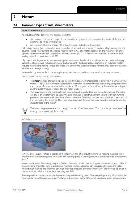
AC induction motor<br />
When 3-phase supply voltage is applied to the stator winding of an induction motor, a rotating magnetic field is<br />
produced which cuts through the rotor bars. The rotating speed of this magnetic field is referred to as "synchronous<br />
speed".<br />
Interaction between the rotating magnetic field and the rotor bars induces a voltage which causes current to flow in<br />
the rotor bars. This rotor current produces a magnetic field in each rotor bar. Interaction between the stator's<br />
rotating magnetic field and the rotor bar magnetic fields produces a torque which causes the rotor to be driven in<br />
the same rotational direction as the stator magnetic field.<br />
Torque produced by the rotor varies from stationary to full running speed. This torque is primarily a function of the<br />
rotor resistance and leakage reactance. The latter is determined by the difference in rotational speed between stator<br />
710-12280-00A <strong>Medium</strong> <strong>Voltage</strong> <strong>Application</strong> <strong>Guide</strong> Page 5