Manual - Supermicro
Manual - Supermicro
Manual - Supermicro

Create successful ePaper yourself
Turn your PDF publications into a flip-book with our unique Google optimized e-Paper software.
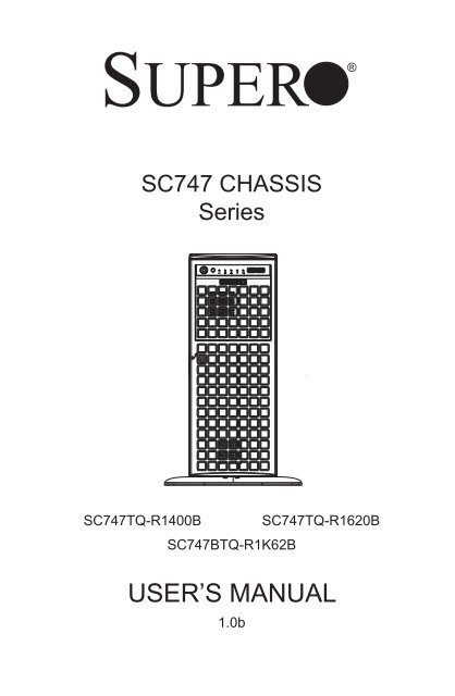
SUPER<br />
®<br />
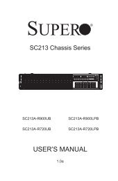
SC747 CHASSIS<br />
Series<br />
SC747TQ-R1400B SC747TQ-R1620B<br />
SC747BTQ-R1K62B<br />
USER’S MANUAL<br />
1.0b
SC747 Chassis <strong>Manual</strong><br />
The information in this User’s <strong>Manual</strong> has been carefully reviewed and is believed to be accurate.<br />
The vendor assumes no responsibility for any inaccuracies that may be contained in this document,<br />
makes no commitment to update or to keep current the information in this manual, or to notify any<br />
person or organization of the updates. Please Note: For the most up-to-date version of this<br />
manual, please see our web site at www.supermicro.com.<br />
Super Micro Computer, Inc. ("<strong>Supermicro</strong>") reserves the right to make changes to the product<br />
described in this manual at any time and without notice. This product, including software and<br />
documentation, is the property of <strong>Supermicro</strong> and/or its licensors, and is supplied only under a<br />
license. Any use or reproduction of this product is not allowed, except as expressly permitted by<br />
the terms of said license.<br />
IN NO EVENT WILL SUPERMICRO BE LIABLE FOR DIRECT, INDIRECT, SPECIAL, INCIDENTAL,<br />
SPECULATIVE OR CONSEQUENTIAL DAMAGES ARISING FROM THE USE OR INABILITY TO<br />
USE THIS PRODUCT OR DOCUMENTATION, EVEN IF ADVISED OF THE POSSIBILITY OF<br />
SUCH DAMAGES. IN PARTICULAR, SUPERMICRO SHALL NOT HAVE LIABILITY FOR ANY<br />
HARDWARE, SOFTWARE, OR DATA STORED OR USED WITH THE PRODUCT, INCLUDING THE<br />
COSTS OF REPAIRING, REPLACING, INTEGRATING, INSTALLING OR RECOVERING SUCH<br />
HARDWARE, SOFTWARE, OR DATA.<br />
Any disputes arising between manufacturer and customer shall be governed by the laws of Santa<br />
Clara County in the State of California, USA. The State of California, County of Santa Clara shall<br />
be the exclusive venue for the resolution of any such disputes. Super Micro's total liability for all<br />
claims will not exceed the price paid for the hardware product.<br />
California Best Management Practices Regulations for Perchlorate Materials: This Perchlorate<br />
warning applies only to products containing CR (Manganese Dioxide) Lithium coin cells. “Perchlorate<br />
Material-special handling may apply. See www.dtsc.ca.gov/hazardouswaste/perchlorate”<br />
WARNING: Handling of lead solder materials used in this<br />
product may expose you to lead, a chemical known to<br />
the State of California to cause birth defects and other<br />
reproductive harm.<br />
<strong>Manual</strong> Revision 1.0b<br />
Release Date: December 26, 2012<br />
Unless you request and receive written permission from Super Micro Computer, Inc., you may not<br />
copy any part of this document.<br />
Information in this document is subject to change without notice. Other products and companies<br />
referred to herein are trademarks or registered trademarks of their respective companies or mark<br />
holders.<br />
Copyright © 2012 by Super Micro Computer, Inc.<br />
All rights reserved.<br />
Printed in the United States of America<br />
ii
Preface<br />
Preface<br />
About This <strong>Manual</strong><br />
This manual is written for professional system integrators and PC technicians. It<br />
provides information for the installation and configuration of the SC747 4U chassis.<br />
Installation and maintenance should be performed by experienced technicians<br />
only.<br />
<strong>Supermicro</strong>'s SC747 server/workstation chassis is truly industry's most powerful<br />
high-performance server chassis. The SC747 offers eleven full-height, full-length<br />
PCI-E expansion slots and four sets of 6-pin and 8-pin power connectors to support<br />
up to four double-width GPU cards. The SC747 comes equipped with optimized<br />
redundant high-efficiency (93%) Gold Level 1400W or 1620W Platinum Level<br />
power supplies with PMBus support and optimized thermal solutions with four<br />
hot-swappable cooling fans and two hot-swappable exhaust fans. In the case of<br />
the SC747BTQ-R1K628B this chassis also supports the option for up to two additional<br />
external rear fans. All of these fans incorporate advanced fan speed controls<br />
to accommodate the most demanding GPU applications. Its eight hot-swappable<br />
SAS/SATA hard drives offer exceptional storage capacity, and three 5.25" storage<br />
modules can rotate 90° to accommodate tower or rack-mounting configurations.<br />
This document lists compatible parts available when this document was published.<br />
Always refer to the our Web site for updates on supported parts and configurations.<br />
iii
SC747 Chassis <strong>Manual</strong><br />
<strong>Manual</strong> Organization<br />
Chapter 1 Introduction<br />
The first chapter provides an overview of the main components included with this<br />
chassis and describes the main features of the SC747 chassis. This chapter also<br />
includes contact information.<br />
Chapter 2 Standardized Warning Statements for AC Systems<br />
This chapter lists warnings, cautions, and system safety. You should thoroughly<br />
familiarize yourself with this chapter for a general overview of safety cautions that<br />
should be followed before installing and servicing this chassis.<br />
Chapter 3 Chassis Components<br />
Refer here for details on this chassis model including the fans, bays, airflow shields,<br />
and other components.<br />
Chapter 4 System Interface<br />
This chapter provides details on the system interface, which includes the functions<br />
and information provided by the control panel on the chassis as well as other LEDs<br />
located throughout the system.<br />
Chapter 5 Chassis Setup and Maintenance<br />
Chapter 5 features detailed information on this chassis. You should follow the<br />
procedures given in this chapter when installing, removing, or reconfiguring your<br />
chassis.<br />
Chapter 6 Rack Installation<br />
Refer to this chapter for detailed information on chassis rack installation. You should<br />
follow the procedures given in this chapter when installing, removing or reconfiguring<br />
your chassis into a rack environment.<br />
iv
Preface<br />
Appendices<br />
This section lists compatible cables, power supply specifications, and compatible<br />
backplanes. Not all compatible backplanes are listed. Refer to our Web site for the<br />
latest compatible backplane information.<br />
Appendix A Chassis Cables<br />
Appendix B Power Supply Specifications<br />
Appendix C SAS-747TQ Backplane <strong>Manual</strong><br />
Appendix D M35S and M35T1 Mobile Rack Specifications<br />
Appendix E M35TQ Mobile Rack Specifications<br />
v
SC747 Chassis <strong>Manual</strong><br />
Table of Contents<br />
Preface........................................................................................................... iii<br />
About This <strong>Manual</strong>..............................................................................................iii<br />
<strong>Manual</strong> Organization...........................................................................................iv<br />
Appendices...........................................................................................................v<br />
Chapter 1 Introduction...............................................................................1-1<br />
1-1 Overview.......................................................................................................... 1-1<br />
1-2 Shipping List..................................................................................................... 1-1<br />
1-3 Chassis Features............................................................................................. 1-2<br />
CPU.................................................................................................................. 1-2<br />
I/O Expansion Slots......................................................................................... 1-2<br />
Peripheral Drives.............................................................................................. 1-2<br />
Other Features................................................................................................. 1-2<br />
Contacting <strong>Supermicro</strong>..................................................................................... 1-3<br />
Chapter 2 Standardized Warning Statements for AC Systems.............2-1<br />
2-1 About Standardized Warning Statements........................................................ 2-1<br />
Warning Definition............................................................................................ 2-1<br />
Installation Instructions..................................................................................... 2-4<br />
Circuit Breaker................................................................................................. 2-5<br />
Power Disconnection Warning......................................................................... 2-6<br />
Equipment Installation...................................................................................... 2-8<br />
Restricted Area................................................................................................. 2-9<br />
Battery Handling............................................................................................. 2-10<br />
Redundant Power Supplies........................................................................... 2-12<br />
Backplane Voltage......................................................................................... 2-13<br />
Comply with Local and National Electrical Codes......................................... 2-14<br />
Product Disposal............................................................................................ 2-15<br />
Hot Swap Fan Warning.................................................................................. 2-16<br />
Power Cable and AC Adapter ....................................................................... 2-18<br />
Chapter 3 Chassis Components...............................................................3-1<br />
3-1 Overview.......................................................................................................... 3-1<br />
3-2 Components..................................................................................................... 3-1<br />
Chassis............................................................................................................. 3-1<br />
Backplane......................................................................................................... 3-1<br />
Fans................................................................................................................. 3-1<br />
Mounting Rails (optional)................................................................................. 3-1<br />
vi
Preface<br />
Power Supply................................................................................................... 3-2<br />
3-3 Where to get Replacement Components......................................................... 3-2<br />
Chapter 4 System Interface.......................................................................4-1<br />
4-1 Overview.......................................................................................................... 4-1<br />
4-2 Control Panel Buttons...................................................................................... 4-2<br />
4-3 Control Panel LEDs......................................................................................... 4-2<br />
4-4 Drive Carrier LEDs........................................................................................... 4-4<br />
SAS/SATA Drives............................................................................................. 4-4<br />
Chapter 5 Chassis Setup and Maintenance............................................5-1<br />
5-1 Overview.......................................................................................................... 5-1<br />
5-2 Installation and Maintenance........................................................................... 5-1<br />
5-3 Chassis Covers................................................................................................ 5-2<br />
Removing the Main Cover............................................................................... 5-3<br />
Opening the Front Cover................................................................................. 5-4<br />
5-4 Configuring the the Storage Module ............................................................... 5-5<br />
Tower or Rack Configuration........................................................................... 5-5<br />
Installing Drives in the Storage Module........................................................... 5-7<br />
Adding Five Hard Drives Using a <strong>Supermicro</strong> Mobile Rack.......................... 5-12<br />
5-5 Installing Hard Drives..................................................................................... 5-14<br />
Installing Hard Drives into the Chassis.......................................................... 5-14<br />
5-6 Installing the Motherboard............................................................................. 5-16<br />
I/O Slot Shield Installation.............................................................................. 5-16<br />
Permanent and Optional Standoffs................................................................ 5-17<br />
Installing the Motherboard............................................................................. 5-18<br />
Installing the Active Heatsink......................................................................... 5-19<br />
Power Supply Connections............................................................................ 5-20<br />
Configuring the Expansion Slots.................................................................... 5-21<br />
Installing Double-Width Graphics Cards........................................................ 5-23<br />
5-7 System Fans.................................................................................................. 5-25<br />
Replacing Mid-Chassis System Fans............................................................ 5-25<br />
Replacing Rear Exhaust Fans....................................................................... 5-26<br />
Adding Optional External Rear Fans (BTQ Model Only)............................... 5-27<br />
5-8 Power Supply ................................................................................................ 5-30<br />
Replacing the Power Supply.......................................................................... 5-30<br />
vii
SC747 Chassis <strong>Manual</strong><br />
Rack Precautions............................................................................................. 6-2<br />
Rack Mounting Considerations........................................................................ 6-2<br />
Removing the Chassis Cover and Feet........................................................... 6-4<br />
Installing the Chassis Handles and Inner Rails............................................... 6-7<br />
Installing the Outer Rails to the Rack.............................................................. 6-8<br />
Installing the Chassis into a Rack................................................................... 6-9<br />
Installing the Chassis Cover.......................................................................... 6-10<br />
Installing Feet on the Chassis........................................................................6-11<br />
Appendix A SC747 Chassis Cables......................................................... A-1<br />
Appendix B SC747 Power Supply Specifications.................................. B-1<br />
Appendix C SAS-747TQ Backplane Specifications............................... C-1<br />
Appendix D M35T1 Mobile Rack Specifications.................................... D-1<br />
Appendix E M35TQ Mobile Rack Specificaitons.....................................E-1<br />
viii
Chapter 1: Introduction<br />
Chapter 1<br />
Introduction<br />
1-1 Overview<br />
<strong>Supermicro</strong>’s SC747 4U chassis features a unique and highly-optimized design.<br />
The chassis is equipped with a high-efficiency power supply. High-performance fans<br />
provide ample optimized cooling for the system and eight hot-swappable drive bays<br />
offer maximum storage capacity in a 4U form factor.<br />
1-2 Shipping List<br />
Please visit the following link for the latest shipping lists and part numbers for your<br />
particular chassis model http://www.supermicro.com/products/chassis/4U/?chs=747.<br />
SC747 Chassis<br />
Model CPU HDD I/O Slots<br />
SC747TQ-R1400B DP/UP 8x SAS/SATA 11x FF<br />
SC747TQ-R1620B DP/UP 8x SAS/SATA 11x FF<br />
SC747BTQ-R1K62B DP/UP 8x SAS/SATA 11x FF<br />
Power<br />
Supply<br />
1400W Redundant<br />
(Gold Level)<br />
1620W Redundant<br />
(Gold Level)<br />
1620W Redundant<br />
(Gold Level)<br />
Legend<br />
UP = Single Processor Support<br />
DP = Dual Processor Support<br />
FF = Full-height, Full-length<br />
1-1
SC747 Chassis <strong>Manual</strong><br />
1-3 Chassis Features<br />
The SC747 4U high-performance chassis includes the following features:<br />
CPU<br />
The SC747 chassis supports single or dual processors.<br />
Hard Drives<br />
The SC747 chassis features eight slots for SAS/SATA drives. These drives are hot<br />
-swappable. Once set up correctly, these drives can be removed without powering<br />
down the server.<br />
I/O Expansion Slots<br />
Each version of the SC747 chassis includes eleven (TQ model) or nine (TG model)<br />
full-height PCI slots for expansion cards.<br />
Peripheral Drives<br />
Each SC747 chassis provides three 5.25” peripheral drive bays for DVD-ROM/DVD-<br />
RW drives, or additional hard drives.These bays are in a rotating cage that allows<br />
for the chassis to be configured in both tower and rack mounted environments.<br />
Other Features<br />
Other on-board features are included to promote system health. These include four<br />
cooling fans, two exhaust fans, a convenient power switch, reset button, and five<br />
LED indicators.<br />
1-2
Chapter 1 Introduction<br />
1-4 Contacting <strong>Supermicro</strong><br />
Headquarters<br />
Address: Super Micro Computer, Inc.<br />
980 Rock Ave.<br />
San Jose, CA 95131 U.S.A.<br />
Tel: +1 (408) 503-8000<br />
Fax: +1 (408) 503-8008<br />
Email: marketing@supermicro.com (General Information)<br />
support@supermicro.com (Technical Support)<br />
Web Site: www.supermicro.com<br />
Europe<br />
Address: Super Micro Computer B.V.<br />
Het Sterrenbeeld 28, 5215 ML<br />
's-Hertogenbosch, The Netherlands<br />
Tel: +31 (0) 73-6400390<br />
Fax: +31 (0) 73-6416525<br />
Email: sales@supermicro.nl (General Information)<br />
support@supermicro.nl (Technical Support)<br />
rma@supermicro.nl (Customer Support)<br />
Asia-Pacific<br />
Address: Super Micro Computer, Inc.<br />
4F, No. 232-1, Liancheng Rd<br />
Chung-Ho Dist., New Taipei City 235<br />
Taiwan<br />
Tel: +886-(2) 8226-3990<br />
Fax: +886-(2) 8226-3991<br />
Web Site: www.supermicro.com.tw<br />
Technical Support:<br />
Email: support@supermicro.com.tw<br />
Tel: +886-(2)-8226-3990<br />
1-3
SC747 Chassis <strong>Manual</strong><br />
Notes<br />
1-4
Chapter 2: Warning Statements for AC Systems<br />
Chapter 2<br />
Standardized Warning Statements for AC Systems<br />
2-1 About Standardized Warning Statements<br />
The following statements are industry standard warnings, provided to warn the user<br />
of situations which have the potential for bodily injury. Should you have questions<br />
or experience difficulty, contact <strong>Supermicro</strong>'s Technical Support department<br />
for assistance. Only certified technicians should attempt to install or configure<br />
components.<br />
Read this appendix in its entirety before installing or configuring components in the<br />
<strong>Supermicro</strong> chassis.<br />
These warnings may also be found on our web site at http://www.supermicro.com/<br />
about/policies/safety_information.cfm.<br />
Warning Definition<br />
Warning!<br />
This warning symbol means danger. You are in a situation that could cause bodily<br />
injury. Before you work on any equipment, be aware of the hazards involved with<br />
electrical circuitry and be familiar with standard practices for preventing accidents.<br />
警 告 の 定 義<br />
この 警 告 サインは 危 険 を 意 味 します。<br />
人 身 事 故 につながる 可 能 性 がありますので、いずれの 機 器 でも 動 作 させる 前 に、<br />
電 気 回 路 に 含 まれる 危 険 性 に 注 意 して、 標 準 的 な 事 故 防 止 策 に 精 通 して 下 さい。<br />
此 警 告 符 号 代 表 危 险 。<br />
您 正 处 于 可 能 受 到 严 重 伤 害 的 工 作 环 境 中 。 在 您 使 用 设 备 开 始 工 作 之 前 , 必 须 充 分<br />
意 识 到 触 电 的 危 险 , 并 熟 练 掌 握 防 止 事 故 发 生 的 标 准 工 作 程 序 。 请 根 据 每 项 警 告 结<br />
尾 的 声 明 号 码 找 到 此 设 备 的 安 全 性 警 告 说 明 的 翻 译 文 本 。<br />
此 警 告 符 號 代 表 危 險 。<br />
您 正 處 於 可 能 身 體 可 能 會 受 損 傷 的 工 作 環 境 中 。 在 您 使 用 任 何 設 備 之 前 , 請 注 意 觸<br />
電 的 危 險 , 並 且 要 熟 悉 預 防 事 故 發 生 的 標 準 工 作 程 序 。 請 依 照 每 一 注 意 事 項 後 的 號<br />
碼 找 到 相 關 的 翻 譯 說 明 內 容 。<br />
2-1
SC216 Chassis <strong>Manual</strong><br />
Warnung<br />
WICHTIGE SICHERHEITSHINWEISE<br />
Dieses Warnsymbol bedeutet Gefahr. Sie befinden sich in einer Situation, die zu<br />
Verletzungen führen kann. Machen Sie sich vor der Arbeit mit Geräten mit den<br />
Gefahren elektrischer Schaltungen und den üblichen Verfahren zur Vorbeugung<br />
vor Unfällen vertraut. Suchen Sie mit der am Ende jeder Warnung angegebenen<br />
Anweisungsnummer nach der jeweiligen Übersetzung in den übersetzten<br />
Sicherheitshinweisen, die zusammen mit diesem Gerät ausgeliefert wurden.<br />
BEWAHREN SIE DIESE HINWEISE GUT AUF.<br />
INSTRUCCIONES IMPORTANTES DE SEGURIDAD<br />
Este símbolo de aviso indica peligro. Existe riesgo para su integridad física. Antes<br />
de manipular cualquier equipo, considere los riesgos de la corriente eléctrica y<br />
familiarícese con los procedimientos estándar de prevención de accidentes. Al<br />
final de cada advertencia encontrará el número que le ayudará a encontrar el texto<br />
traducido en el apartado de traducciones que acompaña a este dispositivo.<br />
GUARDE ESTAS INSTRUCCIONES.<br />
IMPORTANTES INFORMATIONS DE SÉCURITÉ<br />
Ce symbole d'avertissement indique un danger. Vous vous trouvez dans une<br />
situation pouvant entraîner des blessures ou des dommages corporels. Avant<br />
de travailler sur un équipement, soyez conscient des dangers liés aux circuits<br />
électriques et familiarisez-vous avec les procédures couramment utilisées pour<br />
éviter les accidents. Pour prendre connaissance des traductions des avertissements<br />
figurant dans les consignes de sécurité traduites qui accompagnent cet appareil,<br />
référez-vous au numéro de l'instruction situé à la fin de chaque avertissement.<br />
CONSERVEZ CES INFORMATIONS.<br />
תקנון הצהרות א זהרה<br />
הצהרות הבאות הן אזהרות על פי תקני התעשייה, על מנת להזהיר את המשתמש מפני חבלה<br />
פיזית אפשרית. במידה ויש שאלות או היתקלות בבעיה כלשהי, יש ליצור קשר עם מחלקת תמיכה<br />
טכנית של סופרמיקרו. טכנאים מוסמכים בלבד רשאים להתקין או להגדיר את ה רכיבים.<br />
יש לקרוא את הנספח במלואו לפני התקנת או הגדרת הרכיבים במארזי סופרמיקרו.<br />
2-2
Warning Statements for AC Systems<br />
تحذٌز!هذا الزهز ٌعًٌ خطز اًك فً حالة ٌوكي أى تتسبب فً اصابة جسذٌة .<br />
قبل أى تعول على أي هعذات،كي على علن بالوخاطز الٌاجوة عي الذوائز<br />
الكهزبائٍة<br />
وكي على دراٌة بالووارسات الىقائٍة لوٌع وقىع أي حىادث<br />
استخذم رقن البٍاى الوٌصىص فً ًهاٌة كل تحذٌز للعثىر تزجوتها<br />
안전을 위한 주의사항<br />
경고!<br />
이 경고 기호는 위험이 있음을 알려 줍니다. 작업자의 신체에 부상을 야기 할 수<br />
있는 상태에 있게 됩니다. 모든 장비에 대한 작업을 수행하기 전에 전기회로와<br />
관련된 위험요소들을 확인하시고 사전에 사고를 방지할 수 있도록 표준<br />
작업절차를 준수해 주시기 바랍니다.<br />
해당 번역문을 찾기 위해 각 경고의 마지막 부분에 제공된 경고문 번호를<br />
참조하십시오<br />
BELANGRIJKE VEILIGHEIDSINSTRUCTIES<br />
Dit waarschuwings symbool betekent gevaar. U verkeert in een situatie die<br />
lichamelijk letsel kan veroorzaken. Voordat u aan enige apparatuur gaat werken,<br />
dient u zich bewust te zijn van de bij een elektrische installatie betrokken risico's<br />
en dient u op de hoogte te zijn van de standaard procedures om ongelukken te<br />
voorkomen. Gebruik de nummers aan het eind van elke waarschuwing om deze te<br />
herleiden naar de desbetreffende locatie.<br />
BEWAAR DEZE INSTRUCTIES<br />
2-3
SC216 Chassis <strong>Manual</strong><br />
Installation Instructions<br />
Warning!<br />
Read the installation instructions before connecting the system to the power source.<br />
設 置 手 順 書<br />
システムを 電 源 に 接 続 する 前 に、 設 置 手 順 書 をお 読 み 下 さい。<br />
警 告<br />
将 此 系 统 连 接 电 源 前 , 请 先 阅 读 安 装 说 明 。<br />
警 告<br />
將 系 統 與 電 源 連 接 前 , 請 先 閱 讀 安 裝 說 明 。<br />
Warnung<br />
Vor dem Anschließen des Systems an die Stromquelle die Installationsanweisungen<br />
lesen.<br />
¡Advertencia!<br />
Lea las instrucciones de instalación antes de conectar el sistema a la red de<br />
alimentación.<br />
Attention<br />
Avant de brancher le système sur la source d'alimentation, consulter les directives<br />
d'installation.<br />
יש לקרוא את הוראות התקנה לפני חיבור המערכת למקור מתח.<br />
اقر إرشادات التركيب قبل توصيل النظام إلى مصدر للطاقة<br />
시스템을 전원에 연결하기 전에 설치 안내를 읽어주십시오.<br />
Waarschuwing<br />
Raadpleeg de installatie-instructies voordat u het systeem op de voedingsbron<br />
aansluit.<br />
2-4
Chapter 2: Warning Statements for AC Systems<br />
Circuit Breaker<br />
Warning!<br />
This product relies on the building's installation for short-circuit (overcurrent)<br />
protection. Ensure that the protective device is rated not greater than: 250 V, 20 A.<br />
サーキット・ブレーカー<br />
この 製 品 は、 短 絡 ( 過 電 流 ) 保 護 装 置 がある 建 物 での 設 置 を 前 提 としています。<br />
保 護 装 置 の 定 格 が250 V、20 Aを 超 えないことを 確 認 下 さい。<br />
警 告<br />
此 产 品 的 短 路 ( 过 载 电 流 ) 保 护 由 建 筑 物 的 供 电 系 统 提 供 , 确 保 短 路 保 护 设 备 的 额 定 电<br />
流 不 大 于 250V,20A。<br />
警 告<br />
此 產 品 的 短 路 ( 過 載 電 流 ) 保 護 由 建 築 物 的 供 電 系 統 提 供 , 確 保 短 路 保 護 設 備 的 額 定 電<br />
流 不 大 於 250V,20A。<br />
Warnung<br />
Dieses Produkt ist darauf angewiesen, dass im Gebäude ein Kurzschlussbzw.<br />
Überstromschutz installiert ist. Stellen Sie sicher, dass der Nennwert der<br />
Schutzvorrichtung nicht mehr als: 250 V, 20 A beträgt.<br />
¡Advertencia!<br />
Este equipo utiliza el sistema de protección contra cortocircuitos (o sobrecorrientes)<br />
del edificio. Asegúrese de que el dispositivo de protección no sea superior a: 250<br />
V, 20 A.<br />
Attention<br />
Pour ce qui est de la protection contre les courts-circuits (surtension), ce produit<br />
dépend de l'installation électrique du local. Vérifiez que le courant nominal du<br />
dispositif de protection n'est pas supérieur à :250 V, 20 A.<br />
מוצר זה מסתמך על הגנה המותקנת במבנים למניעת קצר חשמלי. יש לוודא כי<br />
המכשיר המגן מפני הקצר החשמלי הוא לא יותר מ-A 250 ,V 20<br />
هذا المنتج يعتمد على معداث الحمايت مه الدوائرالقصيرة التي تم تثبيتها في<br />
المبنى<br />
تأكد من أن تقييم الجهاز الوقائي ليس أكثر من<br />
20A, 250V :<br />
2-5
SC216 Chassis <strong>Manual</strong><br />
경고!<br />
이 제품은 전원의 단락(과전류)방지에 대해서 전적으로 건물의 관련 설비에<br />
의존합니다. 보호장치의 정격이 반드시 250V(볼트), 20A(암페어)를 초과하지<br />
않도록 해야 합니다.<br />
Waarschuwing<br />
Dit product is afhankelijk van de kortsluitbeveiliging (overspanning) van<br />
uw electrische installatie. Controleer of het beveiligde aparaat niet groter<br />
gedimensioneerd is dan 220V, 20A.<br />
Power Disconnection Warning<br />
Warning!<br />
The system must be disconnected from all sources of power and the power cord<br />
removed from the power supply module(s) before accessing the chassis interior to<br />
install or remove system components.<br />
電 源 切 断 の 警 告<br />
システムコンポーネントの 取 り 付 けまたは 取 り 外 しのために、シャーシー 内 部 にアクセス<br />
するには、<br />
システムの 電 源 はすべてのソースから 切 断 され、 電 源 コードは 電 源 モジュールから 取 り<br />
外 す 必 要 があります。<br />
警 告<br />
在 你 打 开 机 箱 并 安 装 或 移 除 内 部 器 件 前 , 必 须 将 系 统 完 全 断 电 , 并 移 除 电 源 线 。<br />
警 告<br />
在 您 打 開 機 殼 安 裝 或 移 除 內 部 元 件 前 , 必 須 將 系 統 完 全 斷 電 , 並 移 除 電 源 線 。<br />
Warnung<br />
Das System muss von allen Quellen der Energie und vom Netzanschlusskabel<br />
getrennt sein, das von den Spg.Versorgungsteilmodulen entfernt wird, bevor es<br />
auf den Chassisinnenraum zurückgreift, um Systemsbestandteile anzubringen oder<br />
zu entfernen.<br />
2-6
Chapter 2: Warning Statements for AC Systems<br />
¡Advertencia!<br />
El sistema debe ser disconnected de todas las fuentes de energía y del cable<br />
eléctrico quitado de los módulos de fuente de alimentación antes de tener acceso<br />
el interior del chasis para instalar o para quitar componentes de sistema.<br />
Attention<br />
Le système doit être débranché de toutes les sources de puissance ainsi que de<br />
son cordon d'alimentation secteur avant d'accéder à l'intérieur du chassis pour<br />
installer ou enlever des composants de systéme.<br />
אזהרה מפני ניתוק חשמלי<br />
אזהרה!<br />
יש לנתק את המערכת מכל מקורות החשמל ויש להסיר את כבל החשמלי מהספק<br />
לפני גישה לחלק הפנימי של המארז לצורך התקנת או הסרת רכיבים.<br />
يجب فصم اننظاو من جميع مصادر انطاقت وإزانت سهك انكهرباء من وحدة امداد<br />
انطاقت قبم<br />
انىصىل إنى انمناطق انداخهيت نههيكم نتثبيج أو إزانت مكىناث الجهاز<br />
경고!<br />
시스템에 부품들을 장착하거나 제거하기 위해서는 섀시 내부에 접근하기 전에<br />
반드시 전원 공급장치로부터 연결되어있는 모든 전원과 전기코드를 분리해주어야<br />
합니다.<br />
Waarschuwing<br />
Voordat u toegang neemt tot het binnenwerk van de behuizing voor het installeren<br />
of verwijderen van systeem onderdelen, dient u alle spanningsbronnen en alle<br />
stroomkabels aangesloten op de voeding(en) van de behuizing te verwijderen<br />
2-7
SC216 Chassis <strong>Manual</strong><br />
Equipment Installation<br />
Warning!<br />
Only trained and qualified personnel should be allowed to install, replace, or service<br />
this equipment.<br />
機 器 の 設 置<br />
トレーニングを 受 け 認 定 された 人 だけがこの 装 置 の 設 置 、 交 換 、またはサービスを 許 可<br />
されています。<br />
警 告<br />
只 有 经 过 培 训 且 具 有 资 格 的 人 员 才 能 进 行 此 设 备 的 安 装 、 更 换 和 维 修 。<br />
警 告<br />
只 有 經 過 受 訓 且 具 資 格 人 員 才 可 安 裝 、 更 換 與 維 修 此 設 備 。<br />
Warnung<br />
Das Installieren, Ersetzen oder Bedienen dieser Ausrüstung sollte nur geschultem,<br />
qualifiziertem Personal gestattet werden.<br />
¡Advertencia!<br />
Solamente el personal calificado debe instalar, reemplazar o utilizar este equipo.<br />
Attention<br />
Il est vivement recommandé de confier l'installation, le remplacement et la<br />
maintenance de ces équipements à des personnels qualifiés et expérimentés.<br />
אזהרה!<br />
צוות מוסמך בלבד רשאי להתקין, להחליף את הציוד או לתת שירות עבור הציוד.<br />
يجب أن يسمح فقط للمىظفيه المؤهليه والمدربيه لتزكيب واستبدال أو خدمة هذا الجهاس<br />
경고!<br />
훈련을 받고 공인된 기술자만이 이 장비의 설치, 교체 또는 서비스를 수행할 수<br />
있습니다.<br />
2-8
Chapter 2: Warning Statements for AC Systems<br />
Waarschuwing<br />
Deze apparatuur mag alleen worden geïnstalleerd, vervangen of hersteld door<br />
geschoold en gekwalificeerd personeel.<br />
Restricted Area<br />
Warning!<br />
This unit is intended for installation in restricted access areas. A restricted access<br />
area can be accessed only through the use of a special tool, lock and key, or other<br />
means of security. (This warning does not apply to workstations).<br />
アクセス 制 限 区 域<br />
このユニットは、アクセス 制 限 区 域 に 設 置 されることを 想 定 しています。<br />
アクセス 制 限 区 域 は、 特 別 なツール、 鍵 と 錠 前 、その 他 のセキュリティの 手 段 を 用 いての<br />
み 出 入 りが 可 能 です。<br />
警 告<br />
此 部 件 应 安 装 在 限 制 进 出 的 场 所 , 限 制 进 出 的 场 所 指 只 能 通 过 使 用 特 殊 工 具 、 锁 和<br />
钥 匙 或 其 它 安 全 手 段 进 出 的 场 所 。<br />
警 告<br />
此 裝 置 僅 限 安 裝 於 進 出 管 制 區 域 , 進 出 管 制 區 域 係 指 僅 能 以 特 殊 工 具 、 鎖 頭 及 鑰 匙<br />
或 其 他 安 全 方 式 才 能 進 入 的 區 域 。<br />
Warnung<br />
Diese Einheit ist zur Installation in Bereichen mit beschränktem Zutritt vorgesehen.<br />
Der Zutritt zu derartigen Bereichen ist nur mit einem Spezialwerkzeug, Schloss und<br />
Schlüssel oder einer sonstigen Sicherheitsvorkehrung möglich.<br />
¡Advertencia!<br />
Esta unidad ha sido diseñada para instalación en áreas de acceso restringido.<br />
Sólo puede obtenerse acceso a una de estas áreas mediante la utilización de una<br />
herramienta especial, cerradura con llave u otro medio de seguridad.<br />
Attention<br />
Cet appareil doit être installée dans des zones d'accès réservés. L'accès à une<br />
zone d'accès réservé n'est possible qu'en utilisant un outil spécial, un mécanisme<br />
de verrouillage et une clé, ou tout autre moyen de sécurité.<br />
2-9
SC216 Chassis <strong>Manual</strong><br />
אזור עם גישה מוגבלת<br />
אזהרה!<br />
יש להתקין את היחידה באזורים שיש בהם הגבלת גישה. הגישה ניתנת בעזרת<br />
כלי אבטחה בלבד )מפתח, מנעול וכד'(.<br />
경고!<br />
تم هذه انىحذة نتركُبها فٍ مناطق محظورة<br />
َمكن انىصىل إنً منطقت محظورة فقط من خالل استخذاو أداة خاصت،<br />
قفم ومفتاح أو أٌ وسُهت أخري نال مألما<br />
تخصيص .<br />
이 장치는 접근이 제한된 구역에 설치하도록 되어있습니다. 특수도구, 잠금 장치 및<br />
키, 또는 기타 보안 수단을 통해서만 접근 제한 구역에 들어갈 수 있습니다.<br />
Waarschuwing<br />
Dit apparaat is bedoeld voor installatie in gebieden met een beperkte toegang.<br />
Toegang tot dergelijke gebieden kunnen alleen verkregen worden door gebruik te<br />
maken van speciaal gereedschap, slot en sleutel of andere veiligheidsmaatregelen.<br />
Battery Handling<br />
Warning!<br />
There is the danger of explosion if the battery is replaced incorrectly. Replace the<br />
battery only with the same or equivalent type recommended by the manufacturer.<br />
Dispose of used batteries according to the manufacturer's instructions<br />
電 池 の 取 り 扱 い<br />
電 池 交 換 が 正 しく 行 われなかった 場 合 、 破 裂 の 危 険 性 があります。 交 換 する 電 池 はメー<br />
カーが 推 奨 する 型 、または 同 等 のものを 使 用 下 さい。 使 用 済 電 池 は 製 造 元 の 指 示 に 従<br />
って 処 分 して 下 さい。<br />
警 告<br />
电 池 更 换 不 当 会 有 爆 炸 危 险 。 请 只 使 用 同 类 电 池 或 制 造 商 推 荐 的 功 能 相 当 的 电 池 更<br />
换 原 有 电 池 。 请 按 制 造 商 的 说 明 处 理 废 旧 电 池 。<br />
警 告<br />
電 池 更 換 不 當 會 有 爆 炸 危 險 。 請 使 用 製 造 商 建 議 之 相 同 或 功 能 相 當 的 電 池 更 換 原 有<br />
電 池 。 請 按 照 製 造 商 的 說 明 指 示 處 理 廢 棄 舊 電 池 。<br />
2-10
Chapter 2: Warning Statements for AC Systems<br />
Warnung<br />
Bei Einsetzen einer falschen Batterie besteht Explosionsgefahr. Ersetzen Sie die<br />
Batterie nur durch den gleichen oder vom Hersteller empfohlenen Batterietyp.<br />
Entsorgen Sie die benutzten Batterien nach den Anweisungen des Herstellers.<br />
Attention<br />
Danger d'explosion si la pile n'est pas remplacée correctement. Ne la remplacer<br />
que par une pile de type semblable ou équivalent, recommandée par le fabricant.<br />
Jeter les piles usagées conformément aux instructions du fabricant.<br />
¡Advertencia!<br />
Existe peligro de explosión si la batería se reemplaza de manera incorrecta.<br />
Reemplazar la batería exclusivamente con el mismo tipo o el equivalente<br />
recomendado por el fabricante. Desechar las baterías gastadas según las<br />
instrucciones del fabricante.<br />
אזהרה!<br />
קיימת סכנת פיצוץ של הסוללה במידה והוחלפה בדרך לא תקינה. יש להחליף<br />
את הסוללה בסוג התואם מחברת יצרן מומלצת.<br />
סילוק הסוללות המשומשות יש לבצע לפי הוראות היצרן.<br />
هناك خطر من انفجار في حالة اسحبذال البطارية بطريقة غير صحيحة فعليل<br />
اسحبذال البطارية<br />
فقط بنفس النىع أو ما يعادلها مما أوصث به الشرمة المصنعة<br />
جخلص من البطاريات المسحعملة وفقا ل حعليمات الشرمة الصانعة<br />
경고!<br />
배터리가 올바르게 교체되지 않으면 폭발의 위험이 있습니다. 기존 배터리와<br />
동일하거나 제조사에서 권장하는 동등한 종류의 배터리로만 교체해야 합니다.<br />
제조사의 안내에 따라 사용된 배터리를 처리하여 주십시오.<br />
Waarschuwing<br />
Er is ontploffingsgevaar indien de batterij verkeerd vervangen wordt. Vervang de<br />
batterij slechts met hetzelfde of een equivalent type die door de fabrikant aanbevolen<br />
wordt. Gebruikte batterijen dienen overeenkomstig fabrieksvoorschriften afgevoerd<br />
te worden.<br />
2-11
SC216 Chassis <strong>Manual</strong><br />
Redundant Power Supplies<br />
Warning!<br />
This unit might have more than one power supply connection. All connections must<br />
be removed to de-energize the unit.<br />
冗 長 電 源 装 置<br />
このユニットは 複 数 の 電 源 装 置 が 接 続 されている 場 合 があります。<br />
ユニットの 電 源 を 切 るためには、すべての 接 続 を 取 り 外 さなければなりません。<br />
警 告<br />
此 部 件 连 接 的 电 源 可 能 不 止 一 个 , 必 须 将 所 有 电 源 断 开 才 能 停 止 给 该 部 件 供 电 。<br />
警 告<br />
此 裝 置 連 接 的 電 源 可 能 不 只 一 個 , 必 須 切 斷 所 有 電 源 才 能 停 止 對 該 裝 置 的 供 電 。<br />
Warnung<br />
Dieses Gerät kann mehr als eine Stromzufuhr haben. Um sicherzustellen, dass<br />
der Einheit kein trom zugeführt wird, müssen alle Verbindungen entfernt werden.<br />
¡Advertencia!<br />
Puede que esta unidad tenga más de una conexión para fuentes de alimentación.<br />
Para cortar por completo el suministro de energía, deben desconectarse todas las<br />
conexiones.<br />
Attention<br />
Cette unité peut avoir plus d'une connexion d'alimentation. Pour supprimer toute<br />
tension et tout courant électrique de l'unité, toutes les connexions d'alimentation<br />
doivent être débranchées.<br />
אם קיים יותר מספק אחד<br />
אזהרה!<br />
ליחדה יש יותר מחיבור אחד של ספק. יש להסיר את כל החיבורים על מנת לרוקן<br />
את היחי דה.<br />
2-12
Chapter 2: Warning Statements for AC Systems<br />
경고!<br />
قد .<br />
يكون لهذا الجهاز عدة اتصاالت بوحدات امداد الطاقة<br />
يجب إزالة كافة االتصاالت لعسل الوحدة عن الكهرباء<br />
이 장치에는 한 개 이상의 전원 공급 단자가 연결되어 있을 수 있습니다. 이 장치에<br />
전원을 차단하기 위해서는 모든 연결 단자를 제거해야만 합니다.<br />
Waarschuwing<br />
Deze eenheid kan meer dan één stroomtoevoeraansluiting bevatten. Alle<br />
aansluitingen dienen verwijderd te worden om het apparaat stroomloos te maken.<br />
Backplane Voltage<br />
Warning!<br />
Hazardous voltage or energy is present on the backplane when the system is<br />
operating. Use caution when servicing.<br />
バックプレーンの 電 圧<br />
システムの 稼 働 中 は 危 険 な 電 圧 または 電 力 が、バックプレーン 上 にかかっています。<br />
修 理 する 際 には 注 意 ください。<br />
警 告<br />
当 系 统 正 在 进 行 时 , 背 板 上 有 很 危 险 的 电 压 或 能 量 , 进 行 维 修 时 务 必 小 心 。<br />
警 告<br />
當 系 統 正 在 進 行 時 , 背 板 上 有 危 險 的 電 壓 或 能 量 , 進 行 維 修 時 務 必 小 心 。<br />
Warnung<br />
Wenn das System in Betrieb ist, treten auf der Rückwandplatine gefährliche<br />
Spannungen oder Energien auf. Vorsicht bei der Wartung.<br />
¡Advertencia!<br />
Cuando el sistema está en funcionamiento, el voltaje del plano trasero es peligroso.<br />
Tenga cuidado cuando lo revise.<br />
Attention<br />
Lorsque le système est en fonctionnement, des tensions électriques circulent sur<br />
le fond de panier. Prendre des précautions lors de la maintenance.<br />
2-13
SC216 Chassis <strong>Manual</strong><br />
경고!<br />
מתח בפנל האחורי<br />
אזהרה!<br />
קיימת סכנת מתח בפנל האחורי בזמן תפעול המערכת. יש להיזהר במהלך<br />
העבודה.<br />
هناك خطز مه التيار الكهزبائي أوالطاقة المىجىدة على اللىحة<br />
عندما يكىن النظام يعمل كه حذرا عند خدمة هذا الجهاس<br />
시스템이 동작 중일 때 후면판 (Backplane)에는 위험한 전압이나 에너지가 발생<br />
합니다. 서비스 작업 시 주의하십시오.<br />
Waarschuwing<br />
Een gevaarlijke spanning of energie is aanwezig op de backplane wanneer het<br />
systeem in gebruik is. Voorzichtigheid is geboden tijdens het onderhoud.<br />
Comply with Local and National Electrical Codes<br />
Warning!<br />
Installation of the equipment must comply with local and national electrical codes.<br />
地 方 および 国 の 電 気 規 格 に 準 拠<br />
機 器 の 取 り 付 けはその 地 方 および 国 の 電 気 規 格 に 準 拠 する 必 要 があります。<br />
警 告<br />
设 备 安 装 必 须 符 合 本 地 与 本 国 电 气 法 规 。<br />
警 告<br />
設 備 安 裝 必 須 符 合 本 地 與 本 國 電 氣 法 規 。<br />
Warnung<br />
Die Installation der Geräte muss den Sicherheitsstandards entsprechen.<br />
¡Advertencia!<br />
La instalacion del equipo debe cumplir con las normas de electricidad locales y<br />
nacionales.<br />
2-14
Chapter 2: Warning Statements for AC Systems<br />
Attention<br />
L'équipement doit être installé conformément aux normes électriques nationales<br />
et locales.<br />
תיאום חוקי החשמל הארצי<br />
אזהרה!<br />
התקנת הציוד חייבת להיות תואמת לחוקי החשמל המקומיים והארציים .<br />
تركيب المعدات الكهربائية يجب أن يمتثل للقىاويه المحلية والىطىية المتعلقة<br />
بالكهرباء<br />
경고!<br />
현 지역 및 국가의 전기 규정에 따라 장비를 설치해야 합니다.<br />
Waarschuwing<br />
Bij installatie van de apparatuur moet worden voldaan aan de lokale en nationale<br />
elektriciteitsvoorschriften.<br />
Product Disposal<br />
Warning!<br />
Ultimate disposal of this product should be handled according to all national laws<br />
and regulations.<br />
製 品 の 廃 棄<br />
この 製 品 を 廃 棄 処 分 する 場 合 、 国 の 関 係 する 全 ての 法 律 ・ 条 例 に 従 い 処 理 する 必 要 が<br />
あります。<br />
警 告<br />
本 产 品 的 废 弃 处 理 应 根 据 所 有 国 家 的 法 律 和 规 章 进 行 。<br />
警 告<br />
本 產 品 的 廢 棄 處 理 應 根 據 所 有 國 家 的 法 律 和 規 章 進 行 。<br />
Warnung<br />
Die Entsorgung dieses Produkts sollte gemäß allen Bestimmungen und Gesetzen<br />
des Landes erfolgen.<br />
2-15
SC216 Chassis <strong>Manual</strong><br />
¡Advertencia!<br />
Al deshacerse por completo de este producto debe seguir todas las leyes y<br />
reglamentos nacionales.<br />
Attention<br />
La mise au rebut ou le recyclage de ce produit sont généralement soumis à des<br />
lois et/ou directives de respect de l'environnement. Renseignez-vous auprès de<br />
l'organisme compétent.<br />
סילוק המוצר<br />
אזהרה!<br />
סילוק סופי של מוצר זה חייב להיות בהתאם להנחיות ו חוקי המדינה.<br />
عند التخلص النهائي من هذا المنتج ينبغي التعامل معه وفقا لجميع القىانين واللىائح الىطنية<br />
경고!<br />
이 제품은 해당 국가의 관련 법규 및 규정에 따라 폐기되어야 합니다.<br />
Waarschuwing<br />
De uiteindelijke verwijdering van dit product dient te geschieden in overeenstemming<br />
met alle nationale wetten en reglementen.<br />
Hot Swap Fan Warning<br />
Warning!<br />
The fans might still be turning when you remove the fan assembly from the chassis.<br />
Keep fingers, screwdrivers, and other objects away from the openings in the fan<br />
assembly's housing.<br />
ファン・ホットスワップの 警 告<br />
シャーシから 冷 却 ファン 装 置 を 取 り 外 した 際 、ファンがまだ 回 転 している 可 能 性 がありま<br />
す。ファンの 開 口 部 に、 指 、ドライバー、およびその 他 のものを 近 づけないで 下 さい。<br />
警 告<br />
当 您 从 机 架 移 除 风 扇 装 置 , 风 扇 可 能 仍 在 转 动 。 小 心 不 要 将 手 指 、 螺 丝 起 子 和 其 他<br />
物 品 太 靠 近 风 扇<br />
2-16
Chapter 2: Warning Statements for AC Systems<br />
警 告<br />
當 您 從 機 架 移 除 風 扇 裝 置 , 風 扇 可 能 仍 在 轉 動 。 小 心 不 要 將 手 指 、 螺 絲 起 子 和 其 他<br />
物 品 太 靠 近 風 扇 。<br />
Warnung<br />
Die Lüfter drehen sich u. U. noch, wenn die Lüfterbaugruppe aus dem Chassis<br />
genommen wird. Halten Sie Finger, Schraubendreher und andere Gegenstände<br />
von den Öffnungen des Lüftergehäuses entfernt.<br />
¡Advertencia!<br />
Los ventiladores podran dar vuelta cuando usted quite ell montaje del ventilador<br />
del chasis. Mandtenga los dedos, los destornilladores y todos los objetos lejos de<br />
las aberturas del ventilador<br />
Attention<br />
Il est possible que les ventilateurs soient toujours en rotation lorsque vous retirerez<br />
le bloc ventilateur du châssis. Prenez garde à ce que doigts, tournevis et autres<br />
objets soient éloignés du logement du bloc ventilateur.<br />
אזהרה!<br />
כאשר מסירים את חלקי המאוורר מהמארז, יתכן והמאווררים עדיין עובדים. יש<br />
להרחיק ל מרחק בטוח את האצבעות וכלי עבודה שונים מהפתחים בתוך המאוורר<br />
مه انممكه أن انمراوح ال تسال تدورعند إزانة كتهة انمروحة مه انهيكم يجب إبقاء<br />
األصابع و مفكات انبراغي<br />
وغيرها مه األشياء بعيدا عه انفتحات في كتهة انمروحة .<br />
경고!<br />
섀시로부터 팬 조립품을 제거할 때 팬은 여전히 회전하고 있을 수 있습니다. 팬<br />
조림품 외관의 열려있는 부분들로부터 손가락 및 스크류드라이버, 다른 물체들이<br />
가까이 하지 않도록 배치해 주십시오.<br />
Waarschuwing<br />
Het is mogelijk dat de ventilator nog draait tijdens het verwijderen van het<br />
ventilatorsamenstel uit het chassis. Houd uw vingers, schroevendraaiers<br />
en eventuele andere voorwerpen uit de buurt van de openingen in de<br />
ventilatorbehuizing.<br />
2-17
SC216 Chassis <strong>Manual</strong><br />
Power Cable and AC Adapter<br />
Warning!<br />
When installing the product, use the provided or designated connection cables,<br />
power cables and AC adaptors. Using any other cables and adaptors could cause<br />
a malfunction or a fire. Electrical Appliance and Material Safety Law prohibits the<br />
use of UL or CSA -certified cables (that have UL/CSA shown on the code) for any<br />
other electrical devices than products designated by <strong>Supermicro</strong> only.<br />
電 源 コードとACアダプター<br />
製 品 を 設 置 する 場 合 、 提 供 または 指 定 された 接 続 ケーブル、 電 源 コードとACアダプター<br />
を 使 用 下 さい。 他 のケーブルやアダプタを 使 用 すると 故 障 や 火 災 の 原 因 になることがあ<br />
ります。 電 気 用 品 安 全 法 は、ULまたはCSA 認 定 のケーブル(UL/CSEマークがコードに 表<br />
記 )を <strong>Supermicro</strong>が 指 定 する 製 品 以 外 に 使 用 することを 禁 止 しています。<br />
警 告<br />
安 装 此 产 品 时 , 请 使 用 本 身 提 供 的 或 指 定 的 连 接 线 , 电 源 线 和 电 源 适 配 器 . 使 用 其 它 线<br />
材 或 适 配 器 可 能 会 引 起 故 障 或 火 灾 。 除 了 <strong>Supermicro</strong> 所 指 定 的 产 品 , 电 气 用 品 和 材<br />
料 安 全 法 律 规 定 禁 止 使 用 未 经 UL 或 CSA 认 证 的 线 材 。( 线 材 上 会 显 示 UL/CSA 符 号 )。<br />
警 告<br />
安 裝 此 產 品 時 , 請 使 用 本 身 提 供 的 或 指 定 的 連 接 線 , 電 源 線 和 電 源 適 配 器 . 使 用 其 它 線<br />
材 或 適 配 器 可 能 會 引 起 故 障 或 火 災 。 除 了 <strong>Supermicro</strong> 所 指 定 的 產 品 , 電 氣 用 品 和 材<br />
料 安 全 法 律 規 定 禁 止 使 用 未 經 UL 或 CSA 認 證 的 線 材 。( 線 材 上 會 顯 示 UL/CSA 符 號 )。<br />
Warnung<br />
Bei der Installation des Produkts, die zur Verfügung gestellten oder benannt<br />
Anschlusskabel, Stromkabel und Netzteile. Verwendung anderer Kabel und Adapter<br />
kann zu einer Fehlfunktion oder ein Brand entstehen. Elektrische Geräte und<br />
Material Safety Law verbietet die Verwendung von UL-oder CSA-zertifizierte Kabel,<br />
UL oder CSA auf der Code für alle anderen elektrischen Geräte als Produkte von<br />
<strong>Supermicro</strong> nur bezeichnet gezeigt haben.<br />
¡Advertencia!<br />
Al instalar el producto, utilice los cables de conexión previstos o designados, los<br />
cables y adaptadores de CA. La utilización de otros cables y adaptadores podría<br />
ocasionar un mal funcionamiento o un incendio. Aparatos Eléctricos y la Ley de<br />
Seguridad del Material prohíbe el uso de UL o CSA cables certificados que tienen<br />
UL o CSA se muestra en el código de otros dispositivos eléctricos que los productos<br />
designados por <strong>Supermicro</strong> solamente.<br />
2-18
Chapter 2: Warning Statements for AC Systems<br />
Attention<br />
Lors de l'installation du produit, utilisez les bables de connection fournis ou désigné.<br />
L'utilisation d'autres cables et adaptateurs peut provoquer un dysfonctionnement<br />
ou un incendie. Appareils électroménagers et de loi sur la sécurité Matériel interdit<br />
l'utilisation de UL ou CSA câbles certifiés qui ont UL ou CSA indiqué sur le code<br />
pour tous les autres appareils électriques que les produits désignés par <strong>Supermicro</strong><br />
seulement.<br />
חשמליים ומתאמי AC<br />
אזהרה!<br />
כאשר מתקינים את המוצר, יש להשתמש בכבלים, ספקים ומתאמים<br />
נועדו וסופקו לשם כך. שימוש בכל כבל או מתאם אחר יכול לגרום לתקלה או<br />
קצר חשמלי. על פי חוקי שימוש במכשירי חשמל וחוקי בטיחות, קיים איסור<br />
להשתמש בכבלים המוסמכים ב- UL או ב- CSA )כשאר מופיע עליהם קוד של<br />
)UL/CSA עבור כל מוצר חשמלי אחר שלא צוין על ידי סופרקמיקרו בלבד.<br />
AC אשר<br />
عىذ تركيب الجهاز يجب استخذام كابالث التىصيل،والكابالث الكهربائيت<br />
ومحىالث التيار المتردد<br />
التي . استخذام أي كابالث ومحىالث أخري يتسبب في حذوث عطل أو حريق<br />
تم تىفيرها لك مع المىتج<br />
األجهسة الكهربائيت ومىاد قاوىن السالمت يحظر استخذام الكابالث<br />
معتمذة مه قبل<br />
ألي أجهسة كهربائيت أخري غير المىتجاث المعيىت مه قبل<br />
التي تحمل<br />
أن .<br />
UL أو CSA<br />
경고!<br />
<strong>Supermicro</strong><br />
) عالمت (UL/CSA<br />
제품을 설치할 때에는 제공되거나 지정된 연결케이블과 전원케이블, AC어댑터를<br />
사용해야 합니다. 그 밖의 다른 케이블들이나 어댑터들은 고장 또는 화재의 원인이<br />
될 수 있습니다. 전기용품안전법 (Electrical Appliance and Material Safety<br />
Law)은 슈퍼마이크로에서 지정한 제품들 외에는 그 밖의 다른 전기 장치들을<br />
위한 UL또는 CSA에서 인증한 케이블(전선 위에 UL/CSA가 표시)들의 사용을<br />
금지합니다.<br />
Waarschuwing<br />
Bij het installeren van het product, gebruik de meegeleverde of aangewezen kabels,<br />
stroomkabels en adapters. Het gebruik van andere kabels en adapters kan leiden<br />
tot een storing of een brand. Elektrisch apparaat en veiligheidsinformatiebladen wet<br />
verbiedt het gebruik van UL of CSA gecertificeerde kabels die UL of CSA die op<br />
de code voor andere elektrische apparaten dan de producten die door <strong>Supermicro</strong><br />
alleen.<br />
2-19
SC216 Chassis <strong>Manual</strong><br />
Notes<br />
2-20
Chapter 3 Chassis Components<br />
Chapter 3<br />
Chassis Components<br />
3-1 Overview<br />
This chapter describes the most common components included with your chassis.<br />
Some components listed may not be included or compatible with your particular<br />
chassis model. For more information, see the installation instructions detailed later<br />
in this manual.<br />
3-2 Components<br />
Chassis<br />
For the latest shipping lists, visit our Web site at: http://www.supermicro.com.<br />
This chassis accepts four hot-swappable system cooling fans and two power supplies.<br />
SC747 models come in dark gray.<br />
Backplane<br />
Each SC747 chassis comes with a 4U backplane. The backplane will support both<br />
SAS and SATA. For more information regarding compatible backplanes, view the<br />
appendices found at the end of this manual. In addition, visit our Web site for the<br />
latest information: http://www.supermicro.com.<br />
Fans<br />
The SC747 chassis accepts four system fans and two rear exhaust fans. SC747BTQ-<br />
R1K628B models can support up to two optional external rear fans. System fans<br />
are powered from the serverboard. These fans are powered by 4-pin connectors.<br />
Mounting Rails (optional)<br />
The SC747 can be placed in a rack for secure storage and use. To set up your<br />
rack, follow the step-by-step instructions included in this manual.<br />
3-1
SC747 Chassis <strong>Manual</strong><br />
Power Supply<br />
SC747 chassis model includes (93%+) Gold Level 1400W redundant (1+1) power<br />
supplies rated at 1400 Watts or redundant 94% Platinum Level power supplies rated<br />
at 1620 Watts. In the unlikely event your power supply fails, replacement is simple<br />
and can be done without tools.<br />
3-3 Where to get Replacement Components<br />
Infrequently, you may need replacement parts for your system. To ensure the highest<br />
level of professional service and technical support, we strongly recommend<br />
purchasing exclusively from our <strong>Supermicro</strong> Authorized Distributors/System Integrators/Resellers.<br />
A list of <strong>Supermicro</strong> Authorized Distributors/System Integrators/<br />
Reseller can be found at: http://www.supermicro.com. Click the Where to Buy link.<br />
3-2
Chapter 4 System Interface<br />
Chapter 4<br />
System Interface<br />
4-1 Overview<br />
There are several LEDs on the control panel as well as others on the drive carriers<br />
to keep you constantly informed of the overall status of the system as well as the<br />
activity and health of specific components. SC747 models have two buttons on<br />
the chassis control panel, a power on/off button and a reset button. This chapter<br />
explains the meanings of all LED indicators and the appropriate response you may<br />
need to take.<br />
Figure 4-1: Front LEDs<br />
4-1
SC747 Chassis <strong>Manual</strong><br />
4-2 Control Panel Buttons<br />
There are two push-buttons located on the front of the chassis, a power on/off<br />
button and a reset button.<br />
• Power: The main power switch is used to apply or remove power from the power<br />
supply to the server system. Turning off the power with this button removes the<br />
main power but keeps standby power supplied to the system. Therefore, you<br />
must unplug system before servicing.<br />
• Reset: The reset button is used to reboot the system.<br />
4-3 Control Panel LEDs<br />
The control panel located on the front of the SC747chassis has five LEDs. These<br />
LEDs provide you with critical information related to different parts of the system.<br />
This section explains what each LED indicates when illuminated and any corrective<br />
action you may need to take.<br />
• HDD: Indicates SAS/SATA drive, and/or DVD-ROM drive activity when flashing.<br />
• NIC1: Indicates network activity on GLAN1 when flashing.<br />
4-2
Chapter 4 System Interface<br />
• NIC2: Indicates network activity on GLAN2 when flashing.<br />
• Overheat/Fan Fail: When this LED flashes it indicates a fan failure. When<br />
continuously on (not flashing) it indicates an overheat condition, which may be<br />
caused by cables obstructing the airflow in the system or the ambient room<br />
temperature being too warm. Check the routing of the cables and make sure<br />
all fans are present and operating normally. You should also check to make<br />
sure that the chassis covers are installed. Finally, verify that the heatsinks are<br />
installed properly. This LED will remain flashing or on as long as the overheat<br />
condition exists.<br />
!<br />
• Power Fail: Indicates a power failure to the system's power supply units.<br />
4-3
SC747 Chassis <strong>Manual</strong><br />
4-4 Drive Carrier LEDs<br />
Your chassis uses SAS/SATA drives.<br />
SAS/SATA Drives<br />
Each SAS/SATA drive carrier has two LEDs.<br />
• Green: Each Serial ATA drive carrier has a green LED. When illuminated, this<br />
green LED (on the front of the SATA drive carrier) indicates drive activity. A connection<br />
to the SATA backplane enables this LED to blink on and off when that<br />
particular drive is being accessed.<br />
• Red: The red LED indicates a SAS/SATA drive failure. If one of the SAS/SATA<br />
drives fail, you should be notified by your system management software.<br />
4-4
Chapter 5 Chassis Setup and Maintenance<br />
Chapter 5<br />
Chassis Setup and Maintenance<br />
5-1 Overview<br />
This chapter covers the steps required to install components and perform maintenance<br />
on the chassis. The only tool you will need to install components and perform<br />
maintenance is a Phillips screwdriver. Print this page to use as a reference while<br />
setting up your chassis.<br />
5-2 Installation and Maintenance<br />
Installation Procedures:<br />
Chassis Covers<br />
Removing the Main Cover<br />
Opening the Front Cover<br />
Configuring the Storage Module<br />
Installing Hard Drives<br />
Installing the Motherboard<br />
IO Shield Installation<br />
Permanent and Optional Standoffs<br />
Installing the Heatsink<br />
Power Supply Connections<br />
Configuring the Expansion Slots<br />
Installing Double-Width Graphics Cards<br />
General Maintenance:<br />
General Maintenance: Systems Fans<br />
General Maintenance: Power Supply<br />
Warning: Except for short periods of time, do NOT operate the server without the<br />
cover in place. The chassis cover must be in place to allow proper airflow and<br />
prevent overheating.<br />
Review the warnings and precautions listed in the manual before setting up or<br />
servicing this chassis. These include information in Chapter 2: System Safety and<br />
the warning/precautions listed in the setup instructions.<br />
5-1
SC747 Chassis <strong>Manual</strong><br />
5-3 Chassis Covers<br />
The SC747 chassis has three covers, the main cover, the top cover and the front<br />
cover. This section of the manual is describes removing the main cover, and opening<br />
the front cover. Removing the top cover is described in Chapter 6, in the section<br />
titled Installing a Chassis onto a Rack.<br />
Top Cover<br />
Main Cover<br />
Front Cover<br />
Figure 5-1: Identifying the Chassis Covers<br />
5-2
Chapter 5 Chassis Setup and Maintenance<br />
Removing the Main Cover<br />
Removing the Chassis Main Cover<br />
1. Power down the system and remove the power cords from the rear of the<br />
power supplies.<br />
2. Lift up and back on the main cover handle, which secures the cover to the<br />
chassis.<br />
3. Lift the main cover off of the chassis.<br />
1<br />
1<br />
Lift Up and Back<br />
on the Main Cover<br />
Handle<br />
12<br />
Lift off the<br />
Main Cover<br />
Figure 5-2: Removing the Main Cover<br />
5-3
SC747 Chassis <strong>Manual</strong><br />
Front Cover Lock<br />
Figure 5-3: Opening the Front Cover<br />
Opening the Front Cover<br />
The front cover houses up to eight hot-swappable hard drives. The cover can be<br />
locked to prevent unauthorized access. The key to this lock is shipped with the<br />
system.<br />
Opening the Front Cover<br />
1. Unlock the front cover using the key shipped with the system.<br />
2. Gently pull the cover open.<br />
5-4
Chapter 5 Chassis Setup and Maintenance<br />
5-4 Configuring the the Storage Module<br />
Storage Module<br />
Figure 5-4: Chassis in Tower Mode<br />
Storage Module<br />
Figure 5-5: Chassis in Rack Mount Mode<br />
Tower or Rack Configuration<br />
The SC747 chassis is shipped in tower mode and can be immediately used as<br />
desktop server. If the chassis is to be used in a rack, the storage module must be<br />
rotated 90 degrees and the storage moudule cover must be replaced with a horizontal<br />
module cover, part number MCP-210-74703-0B. This can be done before,<br />
during, or after setup. It is not necessary to replace the storage module cover when<br />
the chassis is in the tower configuration.<br />
5-5
SC747 Chassis <strong>Manual</strong><br />
Storage Module<br />
Release Lever<br />
Storage Module<br />
Figure 5-6: Remove the Storage Module<br />
Rotating the Storage Module for Rack Mounting<br />
1. Power down the system, remove the power cords from the rear of the power<br />
supplies and open the chassis cover.<br />
2. Locate the storage module and disconnect any cables from the storage module<br />
to any component in the chassis.<br />
3. Push the storage module release lever. This lever unlocks the storage module.<br />
4. Grasp the external edges of the storage module and pull the unit from the<br />
chassis.<br />
5. Turn the storage module 90 degrees as illustrated.<br />
6. Reinsert the module into the chassis and reconnect the cables.<br />
7. Reconnect the power cords and power up the system.<br />
5-6
Chapter 5 Chassis Setup and Maintenance<br />
Figure 5-7: Chassis Storage Module<br />
Installing Drives in the Storage Module<br />
The storage module includes three full-sized drive bays and the front LED panel.<br />
This module can be configured in one of three ways:<br />
1. Add up to three peripheral drives (CD-ROM, DVD-ROM, DVD-RW etc.).<br />
2. Add up to three extra hard drives to the drive trays.<br />
3. Add five hot-swappable hard drives to the storage module. This configuration<br />
requires a mobile rack. More information on mobile rack installation can be<br />
found in the appendices at the end of this manual.<br />
Warning! Enterprise level hard disk drives are recommended for use in <strong>Supermicro</strong><br />
chassis and servers. For information on recommended HDDs, visit the <strong>Supermicro</strong><br />
Web site at http://www.supermicro.com/products/nfo/files/storage/SAS-1-CompList-110909.pdf<br />
5-7
SC747 Chassis <strong>Manual</strong><br />
Drive Carrier<br />
Release Tabs<br />
Figure 5-8: Removing a Drive Carrier<br />
Use the following instructions to add up to three peripheral drives (DVD-ROM, CD-<br />
ROM, etc.) to the drive trays:<br />
Adding Peripheral Drives<br />
1. Power down the system, remove the power cords from the back of the power<br />
supplies and open the chassis cover.<br />
2. Locate the drive carrier release tab for the slot where you want to place the<br />
peripheral drive.<br />
3. Press the release tab and push the drive carrier toward the front of the chassis.<br />
5-8
Chapter 5 Chassis Setup and Maintenance<br />
Hard Drive Carrier<br />
Hard Drive Rails<br />
Figure 5-9: Adding Hard Drive Rails to the DVD-ROM Drive<br />
4. Remove the drive carrier rails from the drive carrier. To do this, you must remove<br />
two screws from each side.<br />
5. Attach the rails to a DVD-ROM, DVD-RW or other peripheral. The rails should fit<br />
any standard sized 5.25" peripherals.<br />
6. Slide the peripheral drive into the chassis until the carrier clicks into place.<br />
7. Repeat these steps for each periperal drive.<br />
5-9
SC747 Chassis <strong>Manual</strong><br />
Drive Carrier<br />
Release Tabs<br />
Figure 5-10: Removing a Drive Carrier<br />
Adding Hard Drives to the Drive Carriers<br />
1. Power down the server, unplug the power cords from the rear of the power<br />
supplies and open the chassis cover.<br />
2. Locate the drive carrier release tab for the slot where you want to place the<br />
hard drive.<br />
5-10
Chapter 5 Chassis Setup and Maintenance<br />
Hard Drive<br />
Drive Carrier<br />
Figure 5-11: Adding a Hard Drive to the Drive Carrier<br />
3. Push the drive carrier toward the front of the chassis.<br />
4. Place the hard drive into the drive carrier. Make sure The hard drive can be<br />
SAS or SATA depending on your motherboard.<br />
5. Secure the hard drive to the carrier with four screws from the bottom.<br />
6. Slide the drive carrier into the chassis until the carrier clicks into place.<br />
7. Repeat these steps for each drive carrier.<br />
5-11
SC747 Chassis <strong>Manual</strong><br />
Drive Carrier<br />
Release Tabs<br />
Figure 5-12: Removing a Drive Carrier<br />
Adding Five Hard Drives Using a <strong>Supermicro</strong> Mobile Rack<br />
The SC747 chassis supports a CSE-M35T-1/CSE-M35TQ mobile rack to install<br />
extra hot-swappable hard drives. The mobile rack goes into the storage module<br />
which goes into the chassis.<br />
For more information on mobile rack installation and use, visit the <strong>Supermicro</strong> Web<br />
site at www.supermicro.com.<br />
Adding Hard Drives to a <strong>Supermicro</strong> Mobile Rack<br />
1. Power down the system, disconnect the power cords from the rear of the<br />
power supplies, and open the chassis cover.<br />
2. Locate the drive release tabs.<br />
5-12
Chapter 5 Chassis Setup and Maintenance<br />
Hard Drive Rails<br />
Hard Drive Carrier<br />
Figure 5-13: Removing the Hard Drive Rails<br />
3. Pull the first drive release tab and push the drive carrier toward the front of<br />
the chassis. Repeat this for all three tabs.<br />
Mobile Rack<br />
Hard Drive<br />
Rails<br />
Figure 5-14: Adding Hard Drive Rails to a Storage Rack<br />
4. Remove the hard drive carrier rails from the hard drive tray. To do this, you<br />
must remove two screws from each side. Do this for all three hard drive carriers.<br />
5. Install two hard drive rails to the mobile rack. Each individual rail requires two<br />
screws. Also, make sure the arrow on the rail points toward the front of the<br />
chassis.<br />
6. Slide the mobile rack into the storage module and chassis.<br />
5-13
C<br />
SC747 Chassis <strong>Manual</strong><br />
5-5 Installing Hard Drives<br />
Release Button<br />
Drive Carrier Handle<br />
Figure 5-15: Installing Hard Drives<br />
Installing Hard Drives into the Chassis<br />
The drives are mounted in drive carriers to simplify their installation and removal<br />
from the chassis. These carriers also help promote proper airflow for the drive bays.<br />
Only enterprise level hard drives are recommended for use in <strong>Supermicro</strong> chassis.<br />
Installing Hard Drives<br />
1. Unlock and open the chassis cover.<br />
2. Press the release button to extend the drive carrier handle.<br />
3. Using the handle, pull the drive carrier out of the drive bay. The drive is<br />
hot-swappable; there are no cables to disconnect.<br />
5-14
Chapter 5 Chassis Setup and Maintenance<br />
4. Remove the screws holding the dummy drive to the drive carrier.<br />
5. Place a hard drive in the drive carrier.<br />
Figure 5-16: Installing a Hard Drive<br />
6. Secure the hard drive to the carrier using four screws.<br />
7. Insert the hard drive into the chassis. To do this:<br />
7a. Press the hard drive release button to extend the drive carrier handle.<br />
7b. Insert the hard drive into the drive bay and close the handle to lock the hard<br />
drive into place.<br />
5-15
SC747 Chassis <strong>Manual</strong><br />
5-6 Installing the Motherboard<br />
I/O Slot Shield Installation<br />
The I/O shield holds the motherboard ports in place. Install the I/O shield before<br />
installing the motherboard.<br />
I/O Shield<br />
Figure 5-17: SC747 Chassis I/O Shield<br />
Installing the I/O Shield<br />
1. Review the documentation that came with your motherboard. Become familiar<br />
with component placement, requirements, and precautions.<br />
2. Power down the system, unplug the power cords from the power supplies and<br />
open the chassis cover.<br />
3. Choose the proper I/O shield for the motherboard you are installing. The I/O<br />
shield should be included in the motherboard packaging.<br />
4. With the illustrations facing the outside of the chassis, place the shield into<br />
the space provided. Once installed, the chassis rear window will hold the I/O<br />
shield in place.<br />
5-16
Chapter 5 Chassis Setup and Maintenance<br />
Permanent and Optional Standoffs<br />
Standoffs prevent short circuits by creating space between the motherboard and<br />
the chassis surface. The SC747 chassis packaging includes optional standoffs<br />
(hexagon shaped posts). These standoffs accept the rounded Phillips head screws<br />
included in the SC747 accessories packaging.<br />
Standoffs<br />
Figure 5-18: Chassis Standoffs<br />
5-17
SC747 Chassis <strong>Manual</strong><br />
Installing the Motherboard<br />
Installing the Motherboard into the Chassis<br />
1. Review the documentation that came with your motherboard. Become familiar<br />
with component placement, requirements, and precautions.<br />
2. Power down the system, disconnect the power cords from the power supplies,<br />
lay the chassis on a flat surface and open the chassis cover.<br />
3. Compare the holes in the motherboard to those in the chassis, then add or<br />
remove standoffs as needed. To do this:<br />
A. Place a hexagonal standoff screw through the bottom the chassis.<br />
B. Secure the screw with the hexagon nut (rounded side down).<br />
4. Lay the motherboard on the chassis aligning the permanent and optional<br />
standoffs.<br />
5. Secure the motherboard to the chassis using the rounded, Phillips head<br />
screws. Do not exceed more than eight pounds of torque per square inch<br />
when tightening down the motherboard.<br />
6. Secure the CPU(s), heatsinks, and other components to the motherboard,<br />
chassis, and/or backplane as needed.<br />
Figure 5-19: Installing the Motherboard<br />
5-18
Chapter 5 Chassis Setup and Maintenance<br />
Installing the Active Heatsink<br />
Figure 5-20: Installing the Active Heatsink<br />
Installation of the active heatsink will vary, depending upon the type of motherboard<br />
used in the chassis. See the information which was supplied with the motherboard<br />
for details on how to properly install the active heatsink on your specific motherboard.<br />
5-19
SC747 Chassis <strong>Manual</strong><br />
Power Supply Connections<br />
Connect each of the following cables, as required, by your motherboard manufacturer.<br />
In some instances, some cables may not need to be connected. Some cables<br />
may not be available with your model.<br />
Name<br />
20-pin or 24-pin<br />
power cable<br />
Hard drive power<br />
cable<br />
8-pin motherboard<br />
cable<br />
4-pin motherboard<br />
cable<br />
5-pin SMBus<br />
power cable<br />
(small)<br />
Qty<br />
1<br />
Power Supply Cable<br />
Connects<br />
to:<br />
Motherboard<br />
2 Backplane<br />
1<br />
1<br />
1<br />
2-pin INT cable 1<br />
Motherboard<br />
Motherboard<br />
Motherboard<br />
Motherboard<br />
Description<br />
20-pin or 24-pin power cable provides<br />
electricity to the motherboard. and has<br />
twenty to twenty-four yellow, black, gray,<br />
red, orange, green and blue wires.<br />
Connect HDD power connectors to the<br />
HDD backplane for hot-swappable HDD<br />
support.<br />
Provides power to the motherboard CPU.<br />
This cable has two black and two yellow<br />
wires.<br />
Provides power to PCI expansion card.<br />
This cable has two black and two yellow<br />
wires.<br />
Allows the SM (System Management)<br />
bus to monitor power supply<br />
Intrusion detection cable allows the system<br />
to log when the server chassis has<br />
been opened.<br />
5-20
Chapter 5 Chassis Setup and Maintenance<br />
Press the Middle of<br />
the Release Tab<br />
Lift the<br />
Release Tab<br />
Figure 5-21: Expansion Card Port<br />
Configuring the Expansion Slots<br />
After the motherboard installation, install expansion cards in the chassis.<br />
Installing Expansion Cards<br />
1. Power down the system, unplug the power cords from the power supplies and<br />
open the chassis cover.<br />
2. Locate the release tab on the top of the PCI slot bracket.<br />
3. Gently apply pressure in the middle of the release tab to unlock the PCI slot<br />
bracket.<br />
5-21
SC747 Chassis <strong>Manual</strong><br />
Figure 5-22: Removing the PCI Card Slot Guard<br />
4. Pull the release tab upward.<br />
5. Remove the screw holding the bracket in place and pull the bracket from the<br />
chassis.<br />
6. Install your expansion card into the PCI slot bracket and motherboard. To do<br />
this, slide the expansion card (with "L" bracket) into the PCI slot and secure<br />
the card to the motherboard.<br />
7. Push the PCI bracket release tab down until it locks into place with an audible<br />
"click".<br />
8. Secure the expansion card with the screw previously removed from the chassis.<br />
9. Repeat this process with each expansion card to be installed into the chassis.<br />
5-22
Chapter 5 Chassis Setup and Maintenance<br />
12<br />
1<br />
Figure 5-23: Installing Graphics Cards<br />
Installing Double-Width Graphics Cards<br />
The SC747 chassis is designed to support up to four double-width, high-end graphics<br />
cards. An eleven slot GPU card holder (MCP-290-74702-0N) is recommended<br />
for this application and may be purchased by visiting the <strong>Supermicro</strong> Web site at<br />
http://www.supermicro.com and clicking on the Where to Buy link.<br />
Installing Double-Width Graphics Cards<br />
1. Follow the instructions in the previous section for opening the PCI slot, and<br />
insert the graphics card into the appropriate PCI slot.<br />
2. Slide the graphics card down onto the motherboard.<br />
5-23
SC747 Chassis <strong>Manual</strong><br />
15<br />
16<br />
14<br />
13<br />
Figure 5-24: Closing the Graphics Card Holder<br />
3. Place the tabs of the MCP-290-74702-0N graphics card holder into the slots<br />
on the wall of the chassis as illustrated.<br />
4. Lower the graphics card holder down onto the card<br />
5. Pull back the slide lock and lower it over the raised tab as illustrated.<br />
6. Push the slide lock forward, allowing the pins of the slide lock to penetrate<br />
the thru holes in the raised tab.<br />
5-24
Chapter 5 Chassis Setup and Maintenance<br />
5-7 System Fans<br />
Six heavy-duty fans provide cooling for the chassis. Four system fans are located in<br />
the mid-section of the chassis with two exhaust fans in the rear. These fans circulate<br />
air through the system as a means of lowering the system's internal temperature.<br />
The fans come pre-installed to the chassis. Each fan is hot-swappable and can be<br />
replaced without removing any connections.<br />
Mid-Chassis Fan<br />
Release Tab<br />
Figure 5-25: Mid-Chassis Fans<br />
Replacing Mid-Chassis System Fans<br />
Replacing Mid-Chassis Fans<br />
1. Determine which fan has failed. Because the fans are hot-swappable, the<br />
system does not need to be powered-down.<br />
2. Press the fan release tab and lift the failed fan from the chassis. Mid-chassis<br />
fans must be pulled straight out of the chassis.<br />
3. Place the new fan into the vacant space in the housing while making sure the<br />
arrows on the top of the fan (indicating air direction) point in the same direction<br />
as the arrows on the other fans. As soon as the fan is connected, it will<br />
begin working.<br />
5-25
SC747 Chassis <strong>Manual</strong><br />
Rear Fan<br />
Release Tab<br />
Figure 5-26: Rear Exhaust Fans<br />
Replacing Rear Exhaust Fans<br />
Replacing the Rear Exhaust Fan<br />
1. Determine which fan is not operational.<br />
2. Press the rear fan release tab.<br />
3. Pull the fan away from the chassis by pulling back the top first.<br />
4. Place the new fan in the chassis, inserting the bottom of the fan first.<br />
5. Push the fan fully into the housing until the fan clicks into place.<br />
5-26
Chapter 5 Chassis Setup and Maintenance<br />
Adding Optional External Rear Fans (BTQ Model Only)<br />
SC747BTQ chassis models support up to two optional external rear fans for additional<br />
cooling. These are mounted over the PCI slots in the rear of the chassis.<br />
These optional fans may be ordered separately (MCP-320-00046-0N-KIT).<br />
Adding Optional External Rear Fans<br />
1. Power down the system, disconnect the power cords from the rear of the<br />
power supplie and open the chassis cover.<br />
2. Remove the PCI slot covers as illustrated in figure 5-22.<br />
3. Remove the plastic PCI slot latch from the rear of the chassis-<br />
3A: Orient the external PCI slot bracket so that the wiring is at the top of the<br />
bracket.<br />
3B: Determine which PCI slot latch aligns with the slot in the top of the external<br />
rear fan bracket.<br />
3C: Open the latch by pressing downward on the latch as illustrated below.<br />
3D:With the latch open, press inward against one side of the latch to release<br />
its hinge pin from the hinge mounting hole in chassis.<br />
3E: Gently move the hinge latch from side to side until it slips out of both<br />
hinge mounting holes and remove it from the chassis.<br />
13E<br />
13C<br />
13D<br />
Figure 5-27: PCI Slot Modification<br />
5-27
SC747 Chassis <strong>Manual</strong><br />
16<br />
Align with Mounting<br />
Holes and Place Screw<br />
Here<br />
15<br />
Run Fan Wiring Here<br />
16<br />
Align with Mounting Holes and<br />
Place Screw Here<br />
14<br />
Place Bracket Mounting<br />
Pins Here<br />
19<br />
Insert Fan Feet into Mounting<br />
Holes Here<br />
18<br />
Figure 5-28: External Rear Fan Bracket Mounting Pin Placement<br />
4. Place two of the loose, metal bracket mounting pins into the holes at the<br />
base of the PCI slots in the position where the fan is to be located in the rear<br />
window. Tighten these pins to the rear window using pliers.<br />
5. Slide the fan wiring into the slot at the top of the external rear fan bracket.<br />
6. Place the external rear fan bracket over the mounting pins placed at the base<br />
of the PCI slots, located in the rear window.<br />
7. Align the holes at the top of the external rear fan bracket with the corresponding<br />
holes at the top of the PCI slot and secure the bracket with two Phillips<br />
head screws.<br />
8. Insert the feet on the bottom of the external rear fan into the corresponding<br />
slots on the bottom of the external rear fan bracket.<br />
9. Push the top of the fan into the bracket until it clicks into the locked position.<br />
5-28
Chapter 5 Chassis Setup and Maintenance<br />
Phillips Head<br />
Mounting Screws<br />
Figure 5-29: Placing the External Rear Fan and Bracket on the Chassis<br />
10. Route the wiring through the open latch slot and into the chassis.<br />
11. For cosmetic purposes the plastic latch clip may be reinstalled in the latch<br />
slot if desired. Additionally, the wiring may be routed along the top of the PCI<br />
slots and concealed by closing the latch of each slot over the wiring.<br />
12. Plug the fan power connector at the end of the fan wiring into the motherboard.<br />
13. Close the chassis, reconnect the power cord and power up the server.<br />
110<br />
Figure 5-30: Routing the Fan Wiring Into the Chassis<br />
5-29
SC747 Chassis <strong>Manual</strong><br />
5-8 Power Supply<br />
Release Tab<br />
Figure 31: Power Supply Release Button<br />
The SC747 chassis is equipped with 1400W or 1620W (redundant) power supplies.<br />
The power supply is auto-switching capable. This enables it to automatically sense<br />
and operate at a 100V to 240V input voltage. An amber light will be illuminated on<br />
the power supply when the power is off. An illuminated green light indicates that<br />
the power supply is operating.<br />
Replacing the Power Supply<br />
With a redundant power supply, the system automatically switches to the second<br />
power supply if the first should fail.<br />
Replacing the Power Supply<br />
1. Power down the system and unplug the power cord from the rear of the<br />
failed power supply. When the system includes a redundant power supply<br />
(two power modules), you can leave the server running and remove only one<br />
power supply.<br />
2. Push the release tab on the back of the power supply as illustrated.<br />
3. Pull the power supply out using the handle provided.<br />
4. Replace the failed power module with another of the same model.<br />
5. Push the new power supply module into the power bay until you hear a click.<br />
6. Plug the AC power cord back into the module and power up the system.<br />
5-30
Chapter 6 Rack Installation<br />
Chapter 6<br />
Rack Installation<br />
6-1 Overview<br />
This chapter provides instuctions for installing your system into a rack environment.<br />
Following the instructions in the order given should enable you to install the system<br />
within a minimal amount of time.<br />
6-2 Unpacking the System<br />
You should inspect the box the chassis was shipped in and note if it was damaged<br />
in any way. If the chassis itself shows damage you should file a damage claim with<br />
the carrier who delivered it.<br />
Decide on a suitable location for the rack unit that will hold your chassis. It should<br />
be situated in a clean, dust-free area that is well ventilated. Avoid areas where<br />
heat, electrical noise and electromagnetic fields are generated. You will also need<br />
it placed near a grounded power outlet. Be sure to read the Rack and Server Precautions<br />
in the next section.<br />
6-3 Preparing for Setup<br />
Optional rail sets MCP-290-00059-0B (26.5" - 36.4") and MCP-290-00058-0N<br />
(19" - 26.6") include two sets of rail assemblies, two rail mounting brackets and<br />
the mounting screws you will need to install the system into the rack. Please read<br />
this section in its entirety before you begin the installation procedure outlined in<br />
the sections that follow.<br />
Choosing a Setup Location<br />
• Leave enough clearance in front of the rack to enable you to open the front<br />
door completely (~25 inches).<br />
• Leave approximately 30 inches of clearance in the back of the rack to allow for<br />
sufficient airflow and ease in servicing.<br />
• This product is for installation only in a Restricted Access Location (dedicated<br />
equipment rooms, service closets and similar environments.).<br />
6-1
SC747 Chassis <strong>Manual</strong><br />
Rack Precautions<br />
• Ensure that the leveling jacks on the bottom of the rack are fully extended to<br />
the floor with the full weight of the rack resting on them.<br />
• In single rack installation, stabilizers should be attached to the rack.<br />
• In multiple rack installations, the racks should be coupled together.<br />
• Always make sure the rack is stable before extending a component from the<br />
rack.<br />
• You should extend only one component at a time - extending two or more simultaneously<br />
may cause the rack to become unstable.<br />
General Server Precautions<br />
• Review the electrical and general safety precautions that came with the components<br />
you are adding to your chassis.<br />
• Determine the placement of each component in the rack before you install the<br />
rails.<br />
• Install the heaviest server components on the bottom of the rack first, and then<br />
work up.<br />
• Use a regulating uninterruptible power supply (UPS) to protect the server from<br />
power surges, voltage spikes and to keep your system operating in case of a<br />
power failure.<br />
• Allow the hot plug hard drives and power supply modules to cool before touching<br />
them.<br />
• Always keep the rack's front door and all panels and components on the servers<br />
closed when not servicing to maintain proper cooling.<br />
Rack Mounting Considerations<br />
Ambient Operating Temperature<br />
If installed in a closed or multi-unit rack assembly, the ambient operating temperature<br />
of the rack environment may be greater than the ambient temperature of the<br />
room. Therefore, consideration should be given to installing the equipment in an<br />
6-2
Chapter 6 Rack Installation<br />
environment compatible with the manufacturer’s maximum rated ambient temperature<br />
(TMRA).<br />
Reduced Airflow<br />
Equipment should be mounted into a rack so that the amount of airflow required<br />
for safe operation is not compromised.<br />
Mechanical Loading<br />
Equipment should be mounted into a rack so that a hazardous condition does not<br />
arise due to uneven mechanical loading.<br />
Circuit Overloading<br />
Consideration should be given to the connection of the equipment to the power<br />
supply circuitry and the effect that any possible overloading of circuits might have<br />
on overcurrent protection and power supply wiring. Appropriate consideration of<br />
equipment nameplate ratings should be used when addressing this concern.<br />
Reliable Ground<br />
A reliable ground must be maintained at all times. To ensure this, the rack itself<br />
should be grounded. Particular attention should be given to power supply connections<br />
other than the direct connections to the branch circuit (i.e. the use of power<br />
strips, etc.).<br />
To prevent bodily injury when mounting or servicing this unit in a rack, you<br />
must take special precautions to ensure that the system remains stable.<br />
The following guidelines are provided to ensure your safety:<br />
• This unit should be mounted at the bottom of the rack if it is the only unit in<br />
the rack.<br />
• When mounting this unit in a partially filled rack, load the rack from the bottom<br />
to the top with the heaviest component at the bottom of the rack.<br />
• If the rack is provided with stabilizing devices, install the stabilizers before<br />
mounting or servicing the unit in the rack.<br />
6-3
SC747 Chassis <strong>Manual</strong><br />
6-4 Installing the Chassis onto a Rack<br />
This section provides information on installing the SC747 chassis into a rack unit<br />
with the rails provided. There are a variety of rack units on the market, which<br />
may mean the assembly procedure will differ slightly. You should also refer to the<br />
installation instructions that came with the rack unit you are using.<br />
NOTE: The outer rail is adjustable, MCP-290-00059-0B (26.5" ~ 36.4") and MCP-<br />
290-00058-0N (19" ~ 26.6").<br />
Removing the Chassis Cover and Feet<br />
The SC747 chassis is shipped with the chassis cover and feet pre-installed. Both<br />
the feet and cover must be removed for before installing the rails.<br />
Chassis Cover<br />
Chassis Feet<br />
Chassis Cover Lock<br />
Figure 6-1: Removing the Feet and Chassis Top Cover<br />
6-4
Chapter 6 Rack Installation<br />
Removing the Chassis Top Cover<br />
1. Locate the chassis cover lock (blue lever) at the rear of the chassis cover.<br />
2. Slide the chassis cover lock to the right and push chassis cover forward.<br />
3. Lift the chassis top cover off the chassis.<br />
Removing the Chassis Feet<br />
1. Place the chassis on its side with the chassis side cover facing upward.<br />
2. Remove the screw holding the chassis foot in place.<br />
3. The foot lock is a tab located in the center of the foot that prevents the foot<br />
from sliding. Using a flat head screwdriver, gently lift the foot lock upward<br />
and slide the foot toward the rear of the chassis.<br />
4. Repeat steps 2 and 3 with each remaining foot.<br />
6-5
SC747 Chassis <strong>Manual</strong><br />
Identifying the Sections of the Rack Rails<br />
The chassis package includes two rack rail assemblies in the rack mounting kit.<br />
Each assembly consists of two sections: An inner fixed chassis rail that secures<br />
directly to the server chassis and an outer fixed rack rail that secures directly to<br />
the rack itself.<br />
Inner Rails<br />
Chassis Handle<br />
Figure 6-2: Identifying the Inner Rails and Chassis Handles<br />
6-6
Chapter 6 Rack Installation<br />
12<br />
Figure 6-3: Installing the Inner Rack Rails<br />
Installing the Chassis Handles and Inner Rails<br />
Installing the Inner Rails<br />
1. Locate the chassis handles and handle screws.<br />
2. Align the chassis handle with the front of the chassis and secure with the<br />
three chassis handle screws.<br />
3. Repeats steps 1 and 2 with the other handle.<br />
4. Locate the inner rails and screws in the shipping package.<br />
5. Align the inner rails against the chassis, as shown. Confirm that the rails are<br />
flushed against the edge of the chassis.<br />
6. Tighten the screws. Do not over-tighten.<br />
7. Repeat steps 5 and 6 with the other inner rail.<br />
Warning: do not pick up the server with the front handles. They are designed<br />
to pull the system from a rack only.<br />
6-7
SC747 Chassis <strong>Manual</strong><br />
Rear Rail<br />
Middle Rail<br />
Secure to the<br />
Rear of the Rack<br />
Attach to Middle Rail<br />
Slide into the Inner Rail<br />
Figure 6-4: Assembling the Outer Rails<br />
Installing the Outer Rails to the Rack<br />
Installing the Outer Rails<br />
1. Attach the rear rail to the middle rail.<br />
2. Adjust both to the proper distance so that the rails fit snugly into the rack.<br />
3. Secure the rear rail with two M5 screws to the rear of the rack.<br />
NOTE: The outer rail is adjustable MCP-290-00059-0B (26.5" - 36.4") and<br />
MCP-290-00058-0N (19" - 26.6").<br />
4. Repeat steps 1-3 for the left outer rail.<br />
6-8
Chapter 6 Rack Installation<br />
Figure 6-5: Installing the Rack Rails<br />
Note: figures are for illustrative purposes only. Always install servers into racks<br />
from the bottom up.<br />
Installing the Chassis into a Rack<br />
Installing the Chassis<br />
1. Confirm that chassis includes the inner rails and the outer rails.<br />
2. Align the inner chassis rails with the front of the outer rack rails.<br />
3. Slide the inner rails into the outer rails, keeping the pressure even on both<br />
sides (you may have to depress the locking tabs when inserting). When the<br />
chassis has been pushed completely into the rack, you should hear the locking<br />
tabs "click" into the locked position.<br />
Stability hazard. The rack stabilizing mechanism must be in place, or the<br />
rack must be bolted to the floor before you slide the unit out for servicing.<br />
Failure to stabilize the rack can cause the rack to tip over.<br />
6-9
SC747 Chassis <strong>Manual</strong><br />
6-5 Tower Mounting Instructions<br />
The SC747 chassis is shipped with the chassis cover and feet pre-installed. To use<br />
the chassis as a desktop server, no other installation is required.<br />
Use the instructions in this section if you have converted the chassis for rack use<br />
and need to return the chassis to tower mounting.<br />
Chassis Cover<br />
Position for Chassis Rack<br />
Mount Handles<br />
Chassis Feet<br />
Figure 6-6: Adding Chassis Feet and Top Cover<br />
Installing the Chassis Cover<br />
Installing the Cover<br />
1. Power down the system and remove the power cords from the rear of the<br />
power supplies.<br />
2. Remove the rack mount front handles.<br />
3. Align the cover post with the corresponding holes on the top of the chassis<br />
and place the cover on top of the chassis. The cover should overhang approximately<br />
one-half inch over the front of the chassis.<br />
4. Slide the chassis cover toward the rear of the chassis to lock the cover into<br />
place.<br />
6-10
Chapter 6 Rack Installation<br />
Chassis Foot<br />
Receptacle<br />
Chassis Foot<br />
Chassis Screws<br />
Figure 6-7: Placing Chassis Feet<br />
Installing Feet on the Chassis<br />
Installing the Chassis Feet<br />
1. Place the chassis foot in the foot receptacle and slide the foot toward the<br />
front of the chassis. The foot should lock into place.<br />
2. Secure the foot to the chassis using one screw enclosed in the packaging.<br />
3. Repeat steps 1 and 2 for the remaining chassis feet.<br />
6-11
SC747 Chassis <strong>Manual</strong><br />
Notes<br />
6-12
Appendix A Chassis Cables<br />
Appendix A<br />
SC747 Chassis Cables<br />
A-1 Overview<br />
This appendix lists supported cables for your chassis system. It only includes the<br />
most commonly used components and configurations. For more compatible cables,<br />
refer to the manufacturer of the motherboard you are using and our web site at:<br />
www.supermicro.com.<br />
A-2 Cables Included with SC747 Chassis (SAS/SATA)<br />
SC747-R1400B, SC747TQ-R1620B, SC747BTQ-R1K62B<br />
Part # Type Length Description<br />
CBL-0157L Cable 40 cm<br />
8-pin to 8-pin ribbon cable with tube<br />
for SGPIO<br />
CBL-0179L Cable 70 cm SATA cable, flat straight-straight<br />
CBL-0071L Cable 30"<br />
CBL-0216L Cable 200 mm<br />
CBL-0286L Cable 30 cm<br />
Round 16-pin to 16-pin ribbon FP<br />
cable<br />
4-pin to 4-pin middle fan power<br />
extension (PWM)<br />
4-pin to 4-pin rear fan power extension<br />
w/ square header (PWM)<br />
A-1
SC747 Chassis <strong>Manual</strong><br />
A-4 Compatible Cables<br />
These cables are compatible with the SC747 chassis.<br />
Alternate SAS/SATA Cables<br />
Some compatible motherboards have different connectors. If your motherboard<br />
has only one SAS connector that the SAS/SATA cables must share, use one of the<br />
following cables. These cables must be purchased separately.<br />
Cable Name: SAS Cable Quantity: 1<br />
Part #: CBL-0175L<br />
Alt. Name: "Big Four"<br />
Description: This cable has one SFF-8484 (32-pin) connector on one end and<br />
four SAS connectors (7 pins each) at the other. This cable connects from the host<br />
(motherboard or other controller) to the backplane SAS hard drive port.<br />
Cable Name: SAS Cable Quantity: 1<br />
Part #: CBL-0116L<br />
Alt. Name: iPass or "Small Four"<br />
Description: This cable has one iPass (SFF-8087/Mini-SAS) connector (36-pin) at<br />
one end and four SAS connectors on one end. This cable connects from the host<br />
(motherboard or other controller) to the backplane SAS hard drive port.<br />
A-2
Appendix A Chassis Cables<br />
Extending Power Cables<br />
Although <strong>Supermicro</strong> chassis are designed with to be efficient and cost-effective,<br />
some compatible motherboards have power connectors located in different areas.<br />
To use these motherboards you may have to extend the power cables to the mother<br />
boards. To do this, use the following chart as a guide.<br />
Power Cable Extenders<br />
Number of Pins Cable Part # Length<br />
24-pin CBL-0042L 7.9” (20 cm)<br />
20-pin CBL-0059L 7.9” (20 cm)<br />
8-pin CBL-0062L 7.9” (20 cm)<br />
4-pin CBL-0060L 7.9” (20 cm)<br />
Front Panel to the Motherboard<br />
The SC747 chassis includes a cable to connect the chassis front panel to the<br />
motherboard. If your motherboard uses a different connector, use the following list<br />
to find a compatible cable.<br />
Number of Pins<br />
(Front Panel)<br />
Front Panel to Motherboard Cable (Ribbon Cable)<br />
Number of Pins<br />
(Motherboard)<br />
Cable Part #<br />
16-pin 16-pin CBL-0049L<br />
16-pin 20-pin CBL-0048<br />
20-pin 20-pin CBL-0047L<br />
16-pin various* CBL-0068L<br />
20-pin various* CBL-0067<br />
* Split cables: Use these cable if your motherboard requires several different connections<br />
from the front panel.<br />
A-3
SC747 Chassis <strong>Manual</strong><br />
Notes<br />
A-4
Appendix B: Power Supply Specifications<br />
Appendix B<br />
SC747 Power Supply Specifications<br />
This appendix lists power supply specifications for your chassis system.<br />
MFR Part #<br />
AC Input<br />
DC Output<br />
+5V standby 4 Amps<br />
DC Output<br />
+12V<br />
With Distributor<br />
PWS-1K41P-1R<br />
Gold Level 1400W (Redundant)<br />
1100W: 100 - 140V, 50 - 60Hz, 9.5 - 13.5 Amps<br />
1400W: 180 - 240V, 50 - 60Hz, 7.0 - 9.5 Amps<br />
92 Amps @ 100-140V<br />
116 Amps @ 180-240V<br />
+5V: 30 Amps<br />
+3.3V: 24 Amps<br />
-12V: 0.6 Amps<br />
MFR Part #<br />
AC Input<br />
PWS-1K62P-1R<br />
Platinum Level 1620W (Redundant)<br />
1000W output @ 100-120V, 12-10 Amps, 50-60Hz<br />
1200W output @ 120-140V, 12-10 Amps, 50-60Hz<br />
1620W output @ 180-240V, 10.5-8 Amps, 50-60Hz<br />
DC Output<br />
+12V<br />
1000W: +12V/84 Amps; +5Vsb/4A<br />
1200W: +12V/100 Amps; +5Vsb/4A<br />
1620W: +12V/150 Amps; +5Vsb/4A<br />
B-1
SC747 Chassis <strong>Manual</strong><br />
Notes<br />
B-2
Appendix C SAS-747TQ Backplane Specitications<br />
Appendix C<br />
SAS-747TQ Backplane Specifications<br />
To avoid personal injury and property damage, carefully follow all the safety steps<br />
listed below when accessing your system or handling the components.<br />
C-1 ESD Safety Guidelines<br />
Electrostatic Discharge (ESD) can damage electronic com ponents. To prevent damage<br />
to your system, it is important to handle it very carefully. The following measures<br />
are generally sufficient to protect your equipment from ESD.<br />
• Use a grounded wrist strap designed to prevent static discharge.<br />
• Touch a grounded metal object before removing a component from the antistatic<br />
bag.<br />
• Handle the backplane by its edges only; do not touch its components, peripheral<br />
chips, memory modules or gold contacts.<br />
• When handling chips or modules, avoid touching their pins.<br />
• Put the card and peripherals back into their antistatic bags when not in use.<br />
C-2 General Safety Guidelines<br />
• Always disconnect power cables before installing or removing any components<br />
from the computer, including the backplane.<br />
• Disconnect the power cable before installing or removing any cables from the<br />
backplane.<br />
• Make sure that the backplane is securely and properly installed on the motherboard<br />
to prevent damage to the system due to power shortage.<br />
C-1
SC747 Chassis <strong>Manual</strong><br />
C-3 An Important Note to Users<br />
All images and layouts shown in this user's guide are based upon the latest revision<br />
available at the time of publishing. The card you have received may or may not look<br />
exactly the same as the graphics shown in this manual.<br />
C-4 Introduction to the SAS-747TQ Backplane<br />
The SAS-747TQ backplane has been designed to utilize the most up-to-date technology<br />
available, providing your system with reliable, high-quality performance.<br />
This manual reflects SAS-747TQ Revision 1.00, the most current release available<br />
at the time of publication. Always refer to the <strong>Supermicro</strong> web site at www.supermicro.com<br />
for the latest updates, compatible parts and supported configurations.<br />
C-2
BZ1<br />
J16<br />
7<br />
1<br />
JP18<br />
C201<br />
C45<br />
J14<br />
1<br />
GND GND +5V<br />
4<br />
7<br />
R6<br />
D3<br />
A<br />
C<br />
A<br />
C<br />
A<br />
C<br />
C203<br />
+12V GND GND<br />
1 4<br />
J12<br />
7<br />
JP35<br />
1<br />
3<br />
JP64<br />
JP25<br />
3 1 3 1<br />
JP35:9072 RST JP25:OH TEMP.<br />
C<br />
2-3:55<br />
1<br />
C119<br />
JP65<br />
JP68<br />
4<br />
J10<br />
7<br />
JP95<br />
JP63<br />
1<br />
3<br />
1<br />
C202<br />
JP56<br />
3<br />
3<br />
4<br />
JP98<br />
JP99<br />
1<br />
1<br />
J8<br />
7<br />
C107<br />
3<br />
RP1<br />
JP84:MODE<br />
1-2:SGPIO<br />
2-3:I2C<br />
U18<br />
RP3<br />
C44<br />
33<br />
48<br />
32<br />
Y1<br />
J7<br />
7<br />
17<br />
49 64<br />
3<br />
C3<br />
U19<br />
1<br />
1<br />
5<br />
6<br />
A<br />
C<br />
4<br />
A<br />
C<br />
J6<br />
7<br />
JP69<br />
3 JP97 1<br />
1<br />
2<br />
A<br />
C<br />
1<br />
JP61<br />
JP60<br />
4<br />
J5<br />
7<br />
Appendix C SAS-747TQ Backplane Specitications<br />
C-5 Front Connectors<br />
+<br />
116<br />
#7<br />
JP18:BUZZER RESET<br />
D54:+12V<br />
D53:+5V<br />
D3:ALARM<br />
R325<br />
D54<br />
R324<br />
D53<br />
SAS747TQ<br />
REV: 1.00<br />
DESIGNED IN USA<br />
#6<br />
1-2: RST<br />
2-3: NO RST<br />
1-2:50<br />
OPEN:45<br />
#5 #4<br />
C<br />
C<br />
U67<br />
SIDEBAND#2<br />
115 114<br />
113 112<br />
11 1<br />
13<br />
I2C#2<br />
JP61:FAN#1 SELECT<br />
JP62:FAN#2 SELECT<br />
JP63:FAN#3 SELECT<br />
JP64:FAN#4 SELECT<br />
1-2:WITH FAN<br />
2-3:NO FAN<br />
12<br />
R154<br />
C135<br />
14<br />
UPGRADE<br />
13<br />
1 JP84<br />
C89<br />
#3 #2<br />
110<br />
C99<br />
U42<br />
1<br />
D47<br />
D45<br />
D51<br />
FAN#1FAIL<br />
FAN#2FAIL<br />
FAN#3FAIL<br />
GND<br />
ACT1<br />
ACT2<br />
ACT3<br />
ACT5<br />
ACT6<br />
ACT7<br />
12<br />
#1 #0<br />
19 18<br />
ACT0<br />
ACT4<br />
SIDEBAND#1<br />
I2C#1<br />
JP66<br />
JP37<br />
JP97:FAN#1 SELECT<br />
JP98:FAN#2 SELECT<br />
JP99:FAN#3 SELECT<br />
1-2:WITH FAN<br />
2-3:NO FAN<br />
+<br />
JP13<br />
+<br />
C124<br />
C121<br />
JP10<br />
FAN#4<br />
16<br />
C64<br />
D58<br />
R99<br />
17 16 16<br />
+<br />
JP26<br />
FAN#2<br />
1 JP62<br />
+<br />
FAN#1<br />
+12V +5V<br />
FAN#3<br />
15<br />
15<br />
Figure C-1: Front Connectors<br />
Front Connectors<br />
1. Upgrade Connector: JP69<br />
2. I 2 C Connector#1: JP37 and I 2 C<br />
Connector#2 JP95<br />
3. Sideband Connector#1: JP66 and<br />
Sideband Connector#2: JP68<br />
4. Chip: MG9072<br />
5. Power Connectors: (4-pin): JP10<br />
and JP13<br />
6. Fan Connectors: JP54, JP56, and<br />
JP60<br />
7. ACT_IN #0-7: JP26<br />
9. SAS Port #1: J6<br />
10. SAS Port #2: J7<br />
11. SAS Port #3: J8<br />
12. SAS Port #4: J10<br />
13. SAS Port #5: J12<br />
14. SAS Port #6: J14<br />
15. SAS Port #7: J16<br />
16. Buzzer: BZ1<br />
8. SAS Port #0: J5<br />
C-3
SC747 Chassis <strong>Manual</strong><br />
C-6 Front Connector and Pin Definitions<br />
1. Upgrade Connector<br />
The upgrade connector, designated JP69, is<br />
used for manufacturer's diagnostic purposes<br />
only.<br />
2. I 2 C Connectors<br />
The I 2 C connectors, designated JP37 and<br />
JP95, are used to monitor HDD activity and<br />
status. See the table on the right for pin definitions.<br />
Pin#<br />
I 2 C Connector<br />
Pin Definitions<br />
Definition<br />
1 Data<br />
2 Ground<br />
3 Clock<br />
4 No Connection<br />
3. Sideband Headers<br />
The sideband headers are designated JP66<br />
and JP68. For SES-2 to work properly, you<br />
must connect an 8-pin sideband cable. See the<br />
table to the right for pin definitions.<br />
NOTE: SGPIO is the default setting for this<br />
backplane.<br />
Pin # Definition<br />
2 SGPIO:<br />
SDIN<br />
Sideband Headers<br />
I 2 C:<br />
Backplane<br />
Addressing<br />
(SB5)<br />
4 SGPIO:<br />
SDOUT<br />
Pin # Definition<br />
1 Controller ID<br />
(SB6)<br />
3 GND (SB2)<br />
I 2 C: Reset<br />
(SB4)<br />
6 GND (SB3) 5 SGPIO:<br />
SLOAD<br />
I 2 C:SDA (SB1)<br />
8 Backplane<br />
ID (SB7)<br />
7 SGPIO:<br />
SCLOCK<br />
I 2 C:SCL (SB0)<br />
10 No Connection<br />
9 No Connection<br />
4. MG9072 Chip<br />
The MG9072 is an enclosure management<br />
chip that supports the SES-2 controller and<br />
SES-2 protocols.<br />
C-4
Appendix C SAS-747TQ Backplane Specitications<br />
5. Backplane Main Power Connectors<br />
The 4-pin connectors, designated JP66 and<br />
JP68 provide power to the backplane. See<br />
the table on the right for pin definitions.<br />
Pin#<br />
Backplane<br />
Main Power<br />
4-Pin Connector<br />
Definition<br />
1 +12V<br />
2 and 3 Ground<br />
4 +5V<br />
6. Fan Connectors<br />
The 4-pin connectors, designated JP54,<br />
JP56, and JP60 provide power to the fans.<br />
See the table on the right for pin definitions.<br />
Fan Connectors<br />
Pin# Definition<br />
1 Ground<br />
2 +12V<br />
3 Tachometer<br />
4 Empty<br />
7. SAS Activity LED Header<br />
The activity LED header, designated JP26,<br />
is used to indicate the activity status of<br />
each SAS drive. The Activity LED Header is<br />
located on the front panel. For the Activity<br />
LED Header to work properly, connect using<br />
a 10-pin LED cable.<br />
Pin # Definition<br />
SAS Activity LED Header<br />
Pin Definitions<br />
Pin # Definition<br />
1 ACT IN#0 6 ACT IN#4<br />
2 ACT IN#1 7 ACT IN#5<br />
3 ACT IN#2 8 ACT IN#6<br />
4 ACT IN#3 9 ACT IN#7<br />
5 Empty 10 Ground<br />
8-15. SAS Ports<br />
The SAS ports are used to connect the SAS<br />
drive cables. The eight ports are designated<br />
#0 - #7. Each port is also compatible with<br />
SATA drives.<br />
C-5
BZ1<br />
J16<br />
7<br />
1<br />
JP18<br />
C201<br />
C45<br />
J14<br />
1<br />
GND GND +5V<br />
4<br />
7<br />
R6<br />
D3<br />
A<br />
C<br />
A<br />
C<br />
A<br />
C<br />
C203<br />
+12V GND GND<br />
1 4<br />
J12<br />
7<br />
JP35<br />
1<br />
3<br />
JP64<br />
JP25<br />
3 1 3 1<br />
JP35:9072 RST JP25:OH TEMP.<br />
C<br />
2-3:55<br />
1<br />
C119<br />
JP65<br />
JP68<br />
4<br />
J10<br />
7<br />
JP95<br />
JP63<br />
1<br />
3<br />
1<br />
C202<br />
JP56<br />
3<br />
3<br />
4<br />
JP98<br />
JP99<br />
1<br />
1<br />
J8<br />
7<br />
C107<br />
3<br />
RP1<br />
JP84:MODE<br />
1-2:SGPIO<br />
2-3:I2C<br />
U18<br />
RP3<br />
C44<br />
33<br />
48<br />
32<br />
Y1<br />
J7<br />
7<br />
17<br />
49 64<br />
3<br />
C3<br />
U19<br />
1<br />
1<br />
5<br />
6<br />
A<br />
C<br />
4<br />
A<br />
C<br />
J6<br />
7<br />
JP69<br />
3 JP97 1<br />
1<br />
2<br />
A<br />
C<br />
1<br />
JP61<br />
JP60<br />
4<br />
J5<br />
7<br />
SC747 Chassis <strong>Manual</strong><br />
C-7 Front Jumper Locations and Pin Definitions<br />
+<br />
JP18<br />
JP18:BUZZER RESET<br />
D54:+12V<br />
D53:+5V<br />
D3:ALARM<br />
R325<br />
D54<br />
R324<br />
D53<br />
SAS747TQ<br />
REV: 1.00<br />
DESIGNED IN USA<br />
JP35<br />
1-2: RST<br />
2-3: NO RST<br />
1-2:50<br />
OPEN:45<br />
C<br />
C<br />
U67<br />
SIDEBAND#2<br />
I2C#2<br />
JP84<br />
JP98<br />
JP99<br />
R154<br />
1 JP84<br />
C89<br />
C99<br />
JP97<br />
JP69<br />
U42<br />
UPGRADE<br />
D47<br />
D45<br />
D51<br />
FAN#1FAIL<br />
FAN#2FAIL<br />
FAN#3FAIL<br />
SIDEBAND#1<br />
I2C#1<br />
JP66<br />
JP37<br />
JP97:FAN#1 SELECT<br />
JP98:FAN#2 SELECT<br />
JP99:FAN#3 SELECT<br />
#7<br />
#6<br />
#5 #4<br />
C135<br />
#3 #2<br />
GND<br />
ACT1<br />
ACT2<br />
ACT3<br />
ACT5<br />
ACT6<br />
ACT7<br />
#1 #0<br />
ACT0<br />
ACT4<br />
1-2:WITH FAN<br />
2-3:NO FAN<br />
JP61:FAN#1 SELECT<br />
JP62:FAN#2 SELECT<br />
JP63:FAN#3 SELECT<br />
JP64:FAN#4 SELECT<br />
1-2:WITH FAN<br />
2-3:NO FAN<br />
D58<br />
C121<br />
+<br />
C64<br />
JP13<br />
+<br />
C124<br />
JP10<br />
FAN#4<br />
R99<br />
+<br />
JP26<br />
FAN#2<br />
1 JP62<br />
+<br />
FAN#1<br />
+12V +5V<br />
JP63<br />
FAN#3<br />
JP62<br />
JP61<br />
Figure C-2: Jumper Locations<br />
Explanation of Jumpers<br />
To modify the operation of the backplane,<br />
jumpers can be used to choose between<br />
optional settings. Jumpers create shorts<br />
between two pins to change the function<br />
of the connector. Pin 1 is identified with<br />
a square solder pad on the printed circuit<br />
board. Note: On two pin jumpers, "Closed"<br />
means the jumper is on and "Open" means<br />
the jumper is off the pins.<br />
Connector<br />
Pins<br />
Jumper<br />
Setting<br />
3 2 1<br />
3 2 1<br />
Jumper Settings<br />
JP35<br />
Jumper Jumper Settings Note<br />
1-2: Reset<br />
2-3: No reset<br />
MG9072 chip reset<br />
C-6
Appendix C SAS-747TQ Backplane Specitications<br />
Socket Settings<br />
Socket Socket Setting Note<br />
JP18<br />
Connected to the front<br />
panel<br />
Buzzer reset*<br />
Press once to disable the buzzer<br />
Press twice to enable the buzzer<br />
*The buzzer sound indicates that a condition requiring immediate attention has<br />
occurred.<br />
The buzzer alarm is triggered by the following conditions:<br />
1. Hard drive failure<br />
2. Fan failure<br />
3. System temperature over 45º Celsius.<br />
Fan Jumper Settings<br />
This backplane can use up to three fans. To utilize each fan, you must configure<br />
both jumpers as instructed below.<br />
Fan Jumper Settings<br />
Jumper Jumper Settings Note<br />
JP61<br />
JP97<br />
JP62<br />
JP98<br />
JP63<br />
JP99<br />
Pins 1-2: Enabled<br />
Pins 2-3: Disabled<br />
Pins 1-2: Enabled<br />
Pins 2-3: Disabled<br />
Pins 1-2: Enabled<br />
Pins 2-3: Disabled<br />
Pins 1-2: Enabled<br />
Pins 2-3: Disabled<br />
Pins 1-2: Enabled<br />
Pins 2-3: Disabled<br />
Pins 1-2: Enabled<br />
Pins 2-3: Disabled<br />
FAN#1 enable/disable<br />
FAN#1 selection for MG9072 chip<br />
FAN#2 enable/disable<br />
FAN#2 selection for MG9072 chip<br />
FAN#3 enable/disable<br />
FAN#3 selection for MG9072 chip<br />
C-7
SC747 Chassis <strong>Manual</strong><br />
I 2 C and SGPIO Modes and Jumper Settings<br />
This backplane can utilize I 2 C or SGPIO. SGPIO is the default mode and can be<br />
used without making changes to your jumpers. The following information details<br />
which jumpers must be configured to use I 2 C mode or restore your backplane to<br />
SGPIO mode.<br />
Jumper<br />
SGPIO and I 2 C Jumper Settings (Default)<br />
SGPIO Jumper<br />
Setting (Default)<br />
I 2 C Jumper<br />
Setting<br />
Note<br />
JP84 Pins 1-2 Pins 2-3 Controller ID #1<br />
C-8
BZ1<br />
J16<br />
7<br />
1<br />
JP18<br />
C201<br />
C45<br />
J14<br />
1 4<br />
7<br />
R6<br />
D3<br />
A<br />
C<br />
A<br />
C<br />
A<br />
C<br />
C203<br />
1 4<br />
J12<br />
7<br />
JP35<br />
3 1 3 1<br />
JP35:9072 RST JP25:OH TEMP.<br />
C<br />
C<br />
2-3:55 C<br />
1<br />
3<br />
JP64<br />
JP25<br />
1<br />
C119<br />
JP65<br />
JP68<br />
4<br />
J10<br />
7<br />
JP95<br />
JP63<br />
1<br />
3<br />
1<br />
C202<br />
JP56<br />
3<br />
3<br />
4<br />
JP98<br />
JP99<br />
1<br />
1<br />
J8<br />
7<br />
C107<br />
3<br />
RP1<br />
JP84:MODE<br />
1-2:SGPIO<br />
2-3:I2C<br />
U18<br />
RP3<br />
C44<br />
33<br />
48<br />
32<br />
Y1<br />
J7<br />
7<br />
17<br />
49 64<br />
3<br />
C3<br />
U19<br />
1<br />
1<br />
5<br />
6<br />
A<br />
C<br />
4<br />
A<br />
C<br />
J6<br />
7<br />
JP69<br />
3 JP97 1<br />
1<br />
2<br />
A<br />
C<br />
1<br />
JP61<br />
JP60<br />
4<br />
J5<br />
7<br />
Y1<br />
C99<br />
Appendix C SAS-747TQ Backplane Specitications<br />
1 JP84<br />
3<br />
D3:ALARM<br />
RP3<br />
D54:+12V<br />
D53:+5V<br />
C-8 Front LED Indicators<br />
C89<br />
33<br />
32<br />
R325<br />
D54<br />
R324<br />
D53<br />
R6<br />
D3<br />
48<br />
A<br />
C<br />
ALARM<br />
LED<br />
+5V LED<br />
A<br />
C<br />
A<br />
C<br />
17<br />
+12V LED<br />
U19<br />
1<br />
5<br />
6<br />
UPGRADE<br />
A<br />
C<br />
A<br />
C<br />
JP69<br />
1<br />
2<br />
A<br />
C<br />
FAN FAIL<br />
#1 #2 #3<br />
LEDs<br />
(Red, on)<br />
U18<br />
RP1<br />
JP84:MODE<br />
1-2:SGPIO<br />
2-3:I2C<br />
J14<br />
7<br />
+<br />
#7<br />
49 64<br />
R325<br />
D54<br />
R324<br />
D53<br />
SAS747TQ<br />
REV: 1.00<br />
DESIGNED IN USA<br />
SAS747TQ #2<br />
JP13<br />
JP10<br />
REV: 1.00<br />
+<br />
J7<br />
JP18:BUZZER RESET<br />
+<br />
7<br />
C124<br />
C121<br />
D54:+12V<br />
D53:+5V<br />
DESIGNED IN USA<br />
D3:ALARM<br />
#6<br />
+12V GND GND +5V<br />
+12V GND GND +5V<br />
1-2: RST<br />
2-3: NO RST<br />
1-2:50<br />
OPEN:45<br />
#5 #4<br />
U67<br />
FAN#4<br />
SIDEBAND#2<br />
I2C#2<br />
JP61:FAN#1 SELECT<br />
JP62:FAN#2 SELECT<br />
JP63:FAN#3 SELECT<br />
JP64:FAN#4 SELECT<br />
1-2:WITH FAN<br />
2-3:NO FAN<br />
R154<br />
C135<br />
U42<br />
J12<br />
C64<br />
FAN#3<br />
3 1<br />
JP97<br />
7<br />
D58<br />
R99<br />
1 JP84<br />
JP35<br />
+<br />
JP26<br />
C89<br />
J6<br />
7<br />
C99<br />
#1<br />
FAN#2<br />
1 JP62<br />
U42<br />
UPGRADE<br />
JP25<br />
D47 FAN#1FAIL<br />
D45 FAN#2FAIL<br />
D51 FAN#3FAIL<br />
D47<br />
D45<br />
D51<br />
FAN#1FAIL<br />
FAN#2FAIL<br />
FAN#3FAIL<br />
3 1 3 1<br />
JP35:9072 RST JP25:OH TEMP.<br />
#3<br />
1-2: RST<br />
OPEN:45 C<br />
#2<br />
2-3: NO RST<br />
1-2:50 C<br />
2-3:55 C<br />
GND<br />
ACT3<br />
ACT2<br />
ACT1<br />
ACT5<br />
ACT6<br />
ACT7<br />
#1 #0<br />
+<br />
ACT0<br />
ACT4<br />
GND<br />
SIDEBAND#1<br />
I2C#1<br />
ACT3<br />
ACT7<br />
FAN#1<br />
U67<br />
JP68<br />
JP66<br />
JP37<br />
JP97:FAN#1 SELECT<br />
JP98:FAN#2 SELECT<br />
JP99:FAN#3 SELECT<br />
1-2:WITH FAN<br />
2-3:NO FAN<br />
ACT2<br />
ACT6<br />
ACT1<br />
ACT5<br />
SIDEBAND#2<br />
ACT0<br />
I2C#2<br />
ACT4<br />
J10<br />
7<br />
JP<br />
Figure C-3: Front LEDs<br />
D58<br />
R99<br />
+<br />
C44<br />
#6<br />
Fan#3 fail Off C3 Failure in Fan#3 (Red light on, steady)<br />
JP26<br />
Front LED Indicators<br />
C203<br />
FAN#2<br />
C-9<br />
1 JP62<br />
#5 #4<br />
LED Normal State Specification<br />
Fan#1 fail Off Failure in Fan#1 (Red light on, steady)<br />
Fan#2 fail Off Failure in Fan#2 (Red light on, steady)<br />
Alarm#1 Off Overheat/drive failure<br />
+5V On<br />
+12V On<br />
C119<br />
2-3:NO FAN<br />
1-2:WITH FAN<br />
Backplane power failure. Light is on during<br />
normal operation.<br />
Backplane power failure. Light is on during<br />
normal operation.<br />
+<br />
JP61:FAN#1 SELECT<br />
JP62:FAN#2 SELECT<br />
JP63:FAN#3 SELECT<br />
JP64:FAN#4 SELECT<br />
J
1<br />
8<br />
22<br />
C<br />
R85<br />
D5<br />
AC<br />
D12<br />
A<br />
R83<br />
1<br />
C<br />
R87<br />
D6<br />
AC<br />
D13<br />
A<br />
R84<br />
1<br />
C<br />
R89<br />
D7<br />
AC<br />
D14<br />
A<br />
R86<br />
1<br />
8<br />
22<br />
C<br />
R90<br />
D8<br />
AC<br />
D15<br />
A<br />
R88<br />
C<br />
R96<br />
D19<br />
AC<br />
D18<br />
A<br />
R95<br />
C<br />
R149<br />
D20 D21<br />
AC<br />
A<br />
C32<br />
R150<br />
C<br />
R165<br />
D23<br />
AC<br />
F10<br />
D22<br />
A<br />
R164<br />
C35<br />
D29<br />
C<br />
R178<br />
AC<br />
R173<br />
SC747 Chassis <strong>Manual</strong><br />
C-9 Rear Connectors and LED Indicators<br />
#0<br />
J1<br />
#1<br />
J2<br />
#2<br />
J3<br />
#3<br />
J4<br />
#4<br />
J9<br />
#5<br />
J11<br />
#6<br />
J13<br />
#7<br />
J15<br />
SAS747TQ REV: 1.00<br />
J1<br />
8 22<br />
J2<br />
8 22<br />
J3<br />
J4<br />
1 8 22<br />
J9<br />
1 8 22<br />
#5<br />
SAS<br />
J11<br />
1<br />
8 22<br />
J13<br />
1<br />
8 22<br />
C140<br />
J15<br />
#0<br />
SAS<br />
SAS<br />
#1<br />
SAS<br />
#2<br />
SAS<br />
#3<br />
#4<br />
SAS<br />
F5<br />
F6<br />
SAS<br />
#6<br />
#7<br />
SAS<br />
FAIL#0<br />
ACT#0<br />
FAIL#1<br />
ACT#1<br />
FAIL#2 ACT#2<br />
FAIL#3<br />
ACT#3<br />
FAIL#4<br />
ACT#4<br />
FAIL#5<br />
ACT#5<br />
FAIL#6<br />
ACT#6<br />
FAIL#7<br />
ACT#7<br />
A D24<br />
D5 D12<br />
D6 D13<br />
D7 D14<br />
D8<br />
D15<br />
D19 D18<br />
D20D21<br />
D23 D22<br />
D29 D24<br />
Figure C-4: Rear Connectors<br />
Rear SAS/SATA Connectors<br />
Rear<br />
Connector<br />
#0 SAS/SATA HDD #0<br />
#1 SAS/SATA HDD #1<br />
#2 SAS/SATA HDD #2<br />
#3 SAS/SATA HDD #3<br />
#4 SAS/SATA HDD #4<br />
#5 SAS/SATA HDD #5<br />
#6 SAS/SATA HDD #6<br />
#7 SAS/SATA HDD #7<br />
SAS Drive<br />
Number<br />
Rear LED Indicators<br />
Rear LED Hard Drive Activity Failure LED<br />
#0 D12 D5<br />
#1 D13 D6<br />
#2 D14 D7<br />
#3 D15 D8<br />
#4 D18 D19<br />
#5 D21 D20<br />
#6 D22 D23<br />
#7 D24 D29<br />
C-10
Appendix D: M35T1 Mobile Rack Specifications-<br />
Appendix D<br />
M35T1 Mobile Rack Specifications<br />
D-1 Overview<br />
This manual is written for system integrators, PC technicians and knowledgeable PC<br />
users who intend to integrate <strong>Supermicro</strong>'s intelligent, highly expandable and costeffective<br />
mobile rack solutions into their systems. It provides the user with detailed<br />
information for the installation and use of the M35T1 mobile rack.<br />
The <strong>Supermicro</strong> M35T1 mobile rack offers the cutting edge technology with greater<br />
flexibility. The CSE-M35T1 supports five Serial ATA hot-swappable hard drives that<br />
yield an unparalleled storage capacity without compromising productivity by eliminating<br />
possible system downtime.<br />
For support of the M35S mobile rack and all other SCSI support contact <strong>Supermicro</strong>'s<br />
technical support department at http://www.supermicro.com.<br />
D-2 Product Features<br />
The M35T1 mobile rack includes the following features:<br />
• Supports SATA<br />
• Supports five 3.5" hot-swappable HDDs or three 5.25" HDDs<br />
Operating Systems Supported<br />
For the most up-to-date information visit the <strong>Supermicro</strong> web site at http://www.<br />
supermicro.com.<br />
• Windows 2000, Windows XP, and Windows 2003<br />
• Linux: Red Hat and SuSE<br />
D-1
SC747 Chassis <strong>Manual</strong><br />
System Monitoring<br />
• Fan failure LED<br />
• Overheat LED indicatior<br />
• Drive activity indicatior<br />
D-3 An Important Note to the User<br />
The pictures or graphics shown in this user's guide were based upon the latest PCB<br />
revision available at the time of the publishing of this manual. The M35T1 mobile<br />
rack you have received may or may not look exactly the same as the graphics<br />
shown in this manual.<br />
D-2
Appendix D: M35T1 Mobile Rack Specifications-<br />
D-4 Returning Merchandise for Service<br />
A receipt or copy of your invoice marked with the date of purchase is required before<br />
any warranty service will be rendered. You can obtain service by calling your vendor<br />
for a Returned Merchandise Authorization (RMA) number. When returning to the<br />
manufacturer, the RMA number should be prominently displayed on the outside of<br />
the shipping carton, and mailed prepaid or hand-carried. Shipping and handling<br />
charges will be applied for all orders that must be mailed when service is complete.<br />
For faster service, RMA authorizations may be requested online (http://www.supermicro.com/support/rma/).<br />
Whenever possible, repack the mobile rack in the original <strong>Supermicro</strong> carton, using<br />
the original packaging material. If these are no longer available, be sure to pack the<br />
mobile rack securely, using packaging material to surround the mobile rack so that<br />
it does not shift within the carton and become damaged during shipping.<br />
This warranty only covers normal consumer use and does not cover damages incurred<br />
in shipping or from failure due to the alteration, misuse, abuse or improper<br />
maintenance of products.<br />
During the warranty period, contact your distributor first for any product problems.<br />
D-3
Appendix D: M35T1 Mobile Rack Specifications-<br />
D-5 SATA-M35 Backplane Specifications<br />
To avoid personal injury and property damage, carefully follow all the safety steps<br />
listed below when accessing your system or handling the components.<br />
D-6 ESD Safety Guidelines<br />
Electrostatic Discharge (ESD) can damage electronic com ponents. To prevent damage<br />
to your system, it is important to handle it very carefully. The following measures<br />
are generally sufficient to protect your equipment from ESD.<br />
• Use a grounded wrist strap designed to prevent static discharge.<br />
• Touch a grounded metal object before removing a component from the antistatic<br />
bag.<br />
• Handle the backplane by its edges only; do not touch its components, peripheral<br />
chips, memory modules or gold contacts.<br />
• When handling chips or modules, avoid touching their pins.<br />
• Put the backplane and peripherals back into their antistatic bags when not in<br />
use.<br />
D-7 General Safety Guidelines<br />
• Always disconnect power cables before installing or removing any components<br />
from the computer, including the mobile rack.<br />
• Disconnect the power cable before installing or removing any cables from the<br />
mobile rack.<br />
• Make sure that the mobile rack is securely and properly installed on the motherboard<br />
to prevent damage to the system due to power shortage.<br />
D-5
SC747 Chassis <strong>Manual</strong><br />
D-8 Introduction to SATA-M35<br />
The M35T1 mobile rack includes a SATA-M35 Serial ATA (SATA) backplane. This<br />
backplane is designed to utilize the most up-to-date technology available, providing<br />
your system with reliable, high-quality performance.<br />
This manual reflects models SATA-M35 Revision 1.01, the most current release<br />
available at the time of publication. Always refer to the <strong>Supermicro</strong> Web site at<br />
http://www.supermicro.com for the latest updates, compatible parts and supported<br />
configurations.<br />
D-6
Appendix D: M35T1 Mobile Rack Specifications-<br />
D-9 SATA-M35 Front Connectors<br />
1<br />
1<br />
12<br />
14<br />
15<br />
16<br />
17<br />
18<br />
13<br />
Figure D-1: SATA-M35 Front Connectors<br />
Front Connectors<br />
1. 4-pin Power Connectors: JP10<br />
and JP13<br />
2. ACT IN: JP26<br />
3. Fan Connector: JP22<br />
4. SATA Port #1 (Channel 1): J5<br />
5. SATA Port #2 (Channel 2): J6<br />
6. SATA Port #3 (Channel 3): J7<br />
7. SATA Port #4 (Channel 4): J8<br />
8. SATA Port #5 (Channel 5): J10<br />
D-7
SC747 Chassis <strong>Manual</strong><br />
D-10 Front Connectors and Pin Definitions<br />
1. Backplane Main Power Connectors<br />
The 4-pin power connectors provide power to<br />
the mobile rack. See the table on the right for<br />
pin definitions.<br />
Pin#<br />
Main Power<br />
4-Pin Connector<br />
Definition<br />
1 +12V<br />
2 and 3 Ground<br />
4 +5V<br />
2. Activity LED Connector<br />
The activity LED connector, designated<br />
JP26, is used to indicate the activity status<br />
of each hard drive. For the activity LED<br />
header to work properly, connect a SATA<br />
LED cable.<br />
Activity LED Connector<br />
Pin# Definition<br />
Act1/LED1 Channel 1<br />
Act2/LED2 Channel 2<br />
Act3/LED3 Channel 3<br />
Act4/LED4 Channel 4<br />
Act5/LED5 Channel 5<br />
3. Fan Connector<br />
The 3-pin connectors, designated JP22,<br />
provides power to the mobile rack fan. See<br />
the table on the right for pin definitions.<br />
Fan Connectors<br />
Pin# Definition<br />
1 Ground<br />
2 +12V<br />
3 Tachometer<br />
4. - 8. SATA Ports<br />
The SATA ports are used to connect the<br />
SATA drive cables. The five ports are designated<br />
Channel #1 - #5.<br />
D-8
Appendix D: M35T1 Mobile Rack Specifications-<br />
D-11 SATA-M35 Front Jumpers and Pin Definitions<br />
JP25<br />
JP18<br />
JP28<br />
Figure D-2: SATA-M35 Front Jumpers<br />
Jumper Settings<br />
Jumper Jumper Settings Note<br />
JP18<br />
JP28<br />
JP25<br />
Open (jumper off): Buzzer enabled<br />
Closed (jumper on): Buzzer disabled<br />
Pins 1-2: Fan enabled<br />
Pins 2-3: Fan disabled<br />
Open (jumper off): 45ºC<br />
1-2: 50ºC<br />
2-3: 55ºC<br />
Buzzer reset*<br />
Fan jumper<br />
Overheat temperature settings.<br />
Buzzer activated at<br />
the temperature indicated.<br />
*The buzzer sound indicates that a condition requiring immediate attention has<br />
occurred.<br />
The buzzer alarm is triggered by the following conditions:<br />
1. Hard drive failure<br />
2. Fan failure<br />
3. System temperature over 45º, 50º or 55º Celsius.<br />
D-9
SC747 Chassis <strong>Manual</strong><br />
Explanation of Jumpers<br />
To modify the operation of the mobile rack,<br />
jumpers can be used to choose between<br />
optional settings. Jumpers create shorts<br />
between two pins to change the function<br />
of the connector. Pin 1 is identified with<br />
a square solder pad on the printed circuit<br />
board. Note: On two pin jumpers, "Closed"<br />
means the jumper is on and "Open" means<br />
the jumper is off the pins.<br />
Connector<br />
Pins<br />
Jumper<br />
Setting<br />
3 2 1<br />
3 2 1<br />
D-10
Appendix D: M35T1 Mobile Rack Specifications-<br />
D-12 Rear Connectors and LED Indicators<br />
The rear of the mobile rack backplane has SATA connectors and LEDs which display<br />
activity or failure status for each of the drives, as well as overheat and drive<br />
failure status.<br />
S-ATA #1<br />
J1<br />
FAIL #1<br />
ACT #1<br />
FAIL #2<br />
ACT #2<br />
FAIL #3<br />
ACT #3<br />
FAIL #4<br />
ACT #4<br />
S-ATA #2<br />
J2<br />
S-ATA #3<br />
J3<br />
S-ATA #4<br />
J4<br />
S-ATA #5<br />
J9<br />
FAIL #5<br />
ACT #5<br />
FAN FAIL OH / DRIVE FAIL<br />
D4<br />
D3<br />
Figure D-3: Rear Connectors and LED Indicators<br />
D-11
SC747 Chassis <strong>Manual</strong><br />
Rear<br />
Connector<br />
Rear SAS/SATA Connectors<br />
Reference<br />
SAS/SATA<br />
Drive Number<br />
S-ATA #1 J1 SATA HDD #0<br />
S-ATA #2 J2 SATA HDD #1<br />
S-ATA #3 J3 SATA HDD #2<br />
S-ATA #4 J4 SATA HDD #3<br />
S-ATA #5 J9 SATA HDD #4<br />
Rear LED Indicators<br />
Rear LED Hard Drive Activity Failure LED<br />
S-ATA #1 D12 D5<br />
S-ATA #2 D13 D6<br />
S-ATA #3 D14 D7<br />
S-ATA #4 D15 D8<br />
S-ATA #5 D18 D19<br />
Mobile Rack Backplane LEDs<br />
D3<br />
D4<br />
LED Hard Drive Activity Failure LED<br />
On<br />
On<br />
Overheat/drive failure LED indicator<br />
(Red light flashing, buzzer on)<br />
Fan failure LED indicator<br />
(Red light flashing, buzzer on)<br />
D-12
SC747 Chassis <strong>Manual</strong><br />
D-12 Preparation for Installation<br />
Tools Required<br />
The following tools are required to install the mobile rack into the chassis:<br />
• Phillips head screwdriver<br />
• Antistatic strap (recommended)<br />
Important Safety Guidelines<br />
This product should be assembled and/or serviced by qualified and experienced<br />
technicians. To avoid personal injury and property damage, carefully follow the<br />
guidelines listed below.<br />
Safety Guidelines<br />
1. Power down the system, unplug the power cords from the rear of the power<br />
supplies and open the chassis cover.<br />
2. When disconnecting cables, label them for easy identification.<br />
3. Use a grounded wrist strap designed to prevent static discharge when handling<br />
components.<br />
4. Save all the screws and fasteners for later use and label them for easy identification.)<br />
5. Follow the installation procedures in the following section of this manual to<br />
remove and install the hard drives, cooling fan, and the back panel of the<br />
mobile rack.<br />
Warning! Enterprise level hard disk drives are recommended for use in <strong>Supermicro</strong><br />
chassis and servers. For information on recommended HDDs, visit the <strong>Supermicro</strong><br />
Web site at http://www.supermicro.com/products/nfo/storage.cfm<br />
D-14
Appendix D: M35T1 Mobile Rack Specifications-<br />
D-13 Installation Procedures<br />
Use the following installation procedures to set up the mobile rack.<br />
WARNING! SAS IDs are assigned automatically by the backplane. Do not set<br />
ID's manually on the drives. SAS termination is enabled by default on the SAS<br />
backplane.<br />
Removing Hard Drive Carriers from the Mobile Rack<br />
The hard drives of the M35T1 mobile rack are mounted in drive carriers to simplify<br />
their installation and removal from the chassis. These carriers also help to promote<br />
proper airflow within the mobile rack drive bays.<br />
Release Button<br />
Figure D-3: Hard Drive Carrier Release Button<br />
Removing Hard Drive Carriers from the Mobile Rack<br />
1. Push the release button on the hard drive carrier, which will extend the drive<br />
handle.<br />
D-15
SC747 Chassis <strong>Manual</strong><br />
Figure D-4: Removing Hard Drives From the Mobile Rack<br />
2. Use the drive handle to carefully pull the drive from the mobile rack.<br />
D-16
Appendix D: M35T1 Mobile Rack Specifications-<br />
Installing Hard Drives into the Hard Drive Carriers<br />
Dummy Drive<br />
Hard Drive Carrier<br />
Figure D-5: The Hard Drive Carrier and Dummy Drive<br />
Warning: Except for short periods of time while swapping hard drives, do not operate<br />
the server with the mobile rack hard drive bays empty. The hard drive carrier<br />
must have a hard drive or dummy drive installed.<br />
1<br />
12<br />
1<br />
Figure D-6: Removing the Dummy Drive from the Hard Drive Carrier<br />
Installing a Hard Drive into the Hard Drive Carrier<br />
1. Remove the two screws holding securing the dummy drive to the hard drive<br />
carrier.<br />
2. Remove the dummy drive from the hard drive carrier.<br />
D-17
SC747 Chassis <strong>Manual</strong><br />
SATA Hard Drive<br />
14<br />
14<br />
Drive Carrier<br />
Figure D-7: Installing the Hard Drive into the Hard Drive Carrier<br />
3. Install a new hard drive into the hard drive carrier with the printed circuit<br />
board side facing downward so that the mounting holes in the hard drive align<br />
with those in the hard drive carrier.<br />
4. Secure the hard drive to the hard drive carrier with the six screws provided.<br />
5. Return the hard drive carrier to the mobile rack. Make sure that the hard drive<br />
carrier handle is returned to the closed and locked position. Repeat these<br />
steps for each hard drive to be installed.<br />
D-18
Appendix D: M35T1 Mobile Rack Specifications-<br />
Connecting Cables to the Mobile Rack<br />
Before connecting cables the mobile rack, the exhaust fan must be removed. In<br />
some circumstances, the backplane may need to be removed.<br />
1<br />
1<br />
Figure D-8: Removing Mobile Rack Fan<br />
Removing the Exhaust Fan and Connecting Cables<br />
1. Simultaneously press inward on the tabs on each side of the fan housing.<br />
D-19
SC747 Chassis <strong>Manual</strong><br />
12<br />
Figure D-9: Removing Mobile Rack Fan<br />
2. Pull the exhaust fan off the rear of the mobile rack.<br />
13<br />
Figure D-10: Removing the Bracket Screw<br />
3. Remove the bracket screw from the side of the mobile rack.<br />
D-20
Appendix D: M35T1 Mobile Rack Specifications-<br />
14<br />
Figure D-11: Removing Mobile Rack Bracket<br />
4. Pull the bracket from the rear of the mobile rack.<br />
5. Connect the SATA cables and power cables to the backplane of the mobile<br />
rack.<br />
6. Replace the bracket, bracket screw, and fan on the mobile rack and reconnect<br />
power to the chassis.<br />
D-21
SC747 Chassis <strong>Manual</strong><br />
Backplane Screw<br />
Locations<br />
Figure D-12: Removing the Mobile Rack Backplane (Optional)<br />
Additional Optional Installation Information<br />
If necessary, before reassembling the mobile rack, the backplane may be removed.<br />
To remove the mobile rack backplane, remove the six screws securing the backplane<br />
to the mobile rack. Carefully pull the backplane from the rear of the mobile rack.<br />
D-22
Appendix E: M35TQ Mobile Rack Specifications<br />
Appendix E<br />
M35TQ Mobile Rack Specificaitons<br />
E-1 Overview<br />
This manual is written for system integrators, PC technicians and knowledgeable PC<br />
users who intend to integrate <strong>Supermicro</strong>'s intelligent, highly expandable and costeffective<br />
mobile rack solutions into their systems. It provides the user with detailed<br />
information for the installation and use of the M35TQ mobile rack.<br />
The <strong>Supermicro</strong> M35TQ mobile rack supports SAS or SATA hard drives, and can<br />
accomodate up to five 3.5" hard drives or three 5.25" hard drives. The M35TQ<br />
showcases today's most advanced technological innovations in modular connectivity<br />
and data transferability, laying the foundation for reliable, effective and scalable<br />
solutions for tomorrow's data communications industry.<br />
E-2 Product Features<br />
The M35TQ mobile rack includes the following features:<br />
• Supports SAS or SATA.<br />
• Supports five 3.5" hot-swappable HDDs or three 5.25" HDDs.<br />
Operating Systems Supported<br />
For the most up-to-date information visit the <strong>Supermicro</strong> Web site at http://www.<br />
supermicro.com<br />
• Windows 2000, Windows XP, and Windows 2003.<br />
• Linux: Red Hat and SuSE.<br />
E-1
SC747 Chassis <strong>Manual</strong><br />
System Monitoring<br />
• Fan failure LED.<br />
• Overheat LED indicatior.<br />
• Drive activity indicatior.<br />
E-3 An Important Note to the User<br />
The pictures or graphics shown in this User's Guide were based upon the latest<br />
PCB revision available at the time of the publishing of this manual. The M35TQ<br />
mobile rack you've received may or may not look exactly the same as the graphics<br />
shown in this manual.<br />
Electrostatic Discharge (ESD) can damage electronic com ponents. To prevent damage<br />
to your system, it is important to handle it very carefully. The following measures<br />
are generally sufficient to protect your equipment from ESD.<br />
• Use a grounded wrist strap designed to prevent static discharge.<br />
• Touch a grounded metal object before removing a component from the antistatic<br />
bag.<br />
• Handle the backplane by its edges only; do not touch its components, peripheral<br />
chips, memory modules or gold contacts.<br />
• When handling chips or modules, avoid touching their pins.<br />
• Put the backplane and peripherals back into their antistatic bags when not in<br />
use.<br />
E-4 General Safety Guidelines<br />
• Always disconnect power cables before installing or removing any components<br />
from the computer, including the mobile rack.<br />
• Disconnect the power cable before installing or removing any cables from the<br />
mobile rack.<br />
• Make sure that the mobile rack is securely and properly installed on the motherboard<br />
to prevent damage to the system due to power shortage.<br />
E-2
Appendix E: M35TQ Mobile Rack Specifications<br />
E-5 Introduction to the SAS-M35TQ Backplane<br />
The M35TQ mobile rack contains a SAS-M35TQ backplane. The SAS-M35TQ<br />
backplane has been designed to utilize the most up-to-date technology available,<br />
providing your system with reliable, high-quality performance.<br />
This manual reflects SAS-M35T Revision 1.01, the most current release available<br />
at the time of publication. Always refer to the <strong>Supermicro</strong> Web site at http://www.supermicro.com<br />
for the latest updates, compatible parts and supported configurations.<br />
E-3
R<br />
SC747 Chassis <strong>Manual</strong><br />
E-6 Front Connectors<br />
1<br />
S UPER<br />
13<br />
12<br />
SASM35TQ<br />
17<br />
18<br />
1<br />
14<br />
REV 1.01<br />
15<br />
1 11<br />
112 1 13 1 14 1 15<br />
16<br />
19<br />
110<br />
Figure E-1: Front Connectors<br />
Front Connectors<br />
1. 4-pin Power Connectors: JP10<br />
and JP13<br />
2. MG9072 Chip<br />
3. JTAG Connector: JP47<br />
4. I 2 C Connector #1: JP44<br />
5. I 2 C Connector #2: JP45<br />
6. Sideband Connector #1: JP51<br />
7. Sideband Connector #2: JP52<br />
8. Upgrade: JP46<br />
9. ACT IN: JP26<br />
10. Fan Connector: JP22<br />
11. SAS Port #0: J5<br />
12. SAS Port #1: J6<br />
13. SAS Port #2: J7<br />
14. SAS Port #3: J8<br />
15. SAS Port #4: J10<br />
E-4
Appendix E: M35TQ Mobile Rack Specifications<br />
E-7 Front Connectors and Pin Definitions<br />
1. Mobile Rack Main Power Connectors<br />
The 4-pin power connectors, designated JP10<br />
and JP13, provide power to the mobile rack.<br />
See the table on the right for pin definitions.<br />
Pin#<br />
Mobile rack<br />
Main Power<br />
4-Pin Connector<br />
Definition<br />
1 +12V<br />
2 and 3 Ground<br />
4 +5V<br />
2. MG9072 Chip<br />
The MG9072 is an enclosure management<br />
chip that supports the SES-2 controller and<br />
SES-2 protocols.<br />
3. JTAG Connector<br />
The JTAG connector, designated JP47, is used<br />
for diagnostic purposes only.<br />
4. and 5. I 2 C Connectors<br />
The I 2 C connectors, designated JP44 and<br />
JP45, are used to monitor the HDD activity<br />
and status. See the table on the right for pin<br />
definitions.<br />
Pin#<br />
I 2 C Connector<br />
Pin Definitions<br />
Definition<br />
1 Data<br />
2 Ground<br />
3 Clock<br />
4 No Connection<br />
E-5
SC747 Chassis <strong>Manual</strong><br />
6. and 7. Sideband Headers<br />
The sideband headers are designated JP51<br />
and JP52. For SES-2 to work properly, an<br />
8-pin sideband cable must be connected.<br />
See the table to the right for pin definitions.<br />
Sideband Headers<br />
Pin # Definition Pin # Definition<br />
2 Mobile rack<br />
Addressing<br />
(SB5)<br />
1 Controller<br />
ID (SB6)<br />
4 Reset (SB4) 3 GND (SB2)<br />
6 GND (SB3) 5 SDA (SB1)<br />
8 Mobile rack<br />
ID (SB7)<br />
10 No Connection<br />
7 SCL (SB0)<br />
9 No Connection<br />
8. Upgrade Connector<br />
The upgrade connector, designated JP46,<br />
is used for diagnostic purposes only. This<br />
connector should only be used by a certified<br />
and experienced technician.<br />
9. Activity LED Header<br />
The activity LED header, designated JP26,<br />
is used to indicate the activity status of<br />
each SAS drive. For the activity LED<br />
header to work properly, connect a 10-pin<br />
LED cable.<br />
SAS Activity LED Header<br />
Pin Definitions<br />
Pin # Definition Pin # Definition<br />
1 ACT IN#0 6 ACT IN#4<br />
2 ACT IN#1 7 ACT IN#5<br />
3 ACT IN#2 8 ACT IN#6<br />
4 ACT IN#3 9 ACT IN#7<br />
5 Ground 10 Empty<br />
10. Fan Connector<br />
The 3-pin connectors, designated JP22,<br />
provides power to the mobile rack fan. See<br />
the table on the right for pin definitions.<br />
Fan Connectors<br />
Pin# Definition<br />
1 Ground<br />
2 +12V<br />
3 Tachometer<br />
11 - 15. SAS/SATA Ports<br />
The SAS/SATA ports are used to connect<br />
the SAS/SATA cables from the ports to the<br />
hard drives. The five ports are designated<br />
#0 - #4.<br />
E-6
R<br />
R<br />
Appendix E: M35TQ Mobile Rack Specifications<br />
E-8 Front Jumper Locations and Pin Definitions<br />
S UPER<br />
SASM35TQ<br />
REV 1.01<br />
S UPER<br />
JP62<br />
JP38<br />
JP29<br />
SASM35TQ<br />
REV 1.01<br />
JP37<br />
JP34<br />
JP36<br />
JP33<br />
JP42<br />
JP50<br />
JP41<br />
JP43 JP61<br />
JP40<br />
JP18<br />
Figure E-2: Front Jumpers<br />
Explanation of Jumpers<br />
To modify the operation of the mobile rack,<br />
jumpers can be used to choose between<br />
optional settings. Jumpers create shorts<br />
between two pins to change the function<br />
of the connector. Pin 1 is identified with<br />
a square solder pad on the printed circuit<br />
board. Note: On two pin jumpers, "Closed"<br />
means the jumper is on and "Open" means<br />
the jumper is off the pins.<br />
E-7<br />
Connector<br />
Pins<br />
Jumper<br />
Setting<br />
3 2 1<br />
3 2 1
R<br />
R<br />
SC747 Chassis <strong>Manual</strong><br />
S UPER<br />
S UPER<br />
SASM35TQ<br />
JP29<br />
REV 1.01<br />
SASM35TQ<br />
REV 1.01<br />
JP18<br />
Figure E-3: Buzzer and Chip Reset Jumpers<br />
Buzzer and Chip Reset Jumper Settings<br />
Jumper Settings<br />
Jumper Jumper Settings Note<br />
JP18<br />
JP29<br />
Open: Enabled<br />
Closed: Disabled<br />
Open: Default<br />
Closed: Reset<br />
Buzzer reset*<br />
MG9072 chip reset<br />
*The buzzer sound indicates that a condition requiring immediate attention has<br />
occurred.<br />
The buzzer alarm is triggered by the following conditions:<br />
1. Hard drive failure<br />
2. Fan failure<br />
3. System temperature over 45º Celsius.<br />
E-8
R<br />
R<br />
Appendix E: M35TQ Mobile Rack Specifications<br />
S UPER<br />
SASM35TQ<br />
REV 1.01<br />
JP62<br />
S UPER<br />
SASM35TQ<br />
JP61<br />
REV 1.01<br />
Figure E-4: Fan Jumpers<br />
Fan Jumper Settings<br />
This mobile rack can utilize up to four fans. To use each fan, you must configure<br />
both jumpers as instructed below.<br />
Fan Jumper Settings<br />
Jumper Jumper Settings Note<br />
JP61<br />
JP62<br />
Closed: With fan<br />
Open: No fan<br />
Pins 1-2: With fan<br />
Pins 2-3: No fan<br />
FAN#1<br />
FAN#1<br />
E-9
R<br />
R<br />
SC747 Chassis <strong>Manual</strong><br />
S UPER<br />
SASM35TQ<br />
S UPER<br />
JP38<br />
REV 1.01<br />
SASM35TQ<br />
JP37 JP36<br />
JP33<br />
JP43<br />
JP50<br />
JP41<br />
JP40<br />
REV 1.01<br />
JP34<br />
JP42<br />
Figure E-5: I 2 C and SGPIO Jumpers<br />
I 2 C and SGPIO Modes and Jumper Settings<br />
This mobile rack can utilize I 2 C or SGPIO. I 2 C is the default mode and can be used<br />
without making changes to your jumpers. The following information details which<br />
jumpers must be configured to use SGPIO mode or restore your mobile rack to<br />
I 2 C mode.<br />
Jumper<br />
I 2 C Setting<br />
(Default)<br />
I 2 C/SGPIO Settings<br />
SGPIO<br />
Setting<br />
JP33 Pins 2-3 1-2 Controller ID #1<br />
JP34 Pins 1-2: ID#0 1-2: ID#0 Backplane ID #1<br />
JP36 Pins 2-3 1-2 Controller ID #2<br />
JP37 Pins 2-3: ID#1 1-2: ID#0 Backplane ID #2<br />
JP38 Closed Open I 2 C reset #2<br />
Description<br />
JP40 Open Closed I 2 C reset SDOUT #1<br />
JP41 Open Closed I 2 C reset SDOUT #2<br />
JP42 Pins 2-3 1-2 Backplane ID SDIN #1<br />
JP43 Pins 2-3 1-2 Backplane ID SDIN #2<br />
JP50 Closed Open I 2 C reset #1<br />
E-10
Appendix E: M35TQ Mobile Rack Specifications<br />
E-9 Rear Connectors and LED Indicators<br />
The rear of the mobile rack backplane has SAS/SATA connectors and LEDs which<br />
display activity or failure status for each of the drives, as well as overheat and<br />
drive failure status.<br />
FAIL #0<br />
SAS<br />
#0<br />
SAS #0<br />
J1<br />
SAS<br />
#0<br />
ACT #0<br />
FAIL #1<br />
SAS<br />
#1<br />
SAS #1<br />
J2<br />
SAS<br />
#1<br />
ACT #1<br />
FAIL #2<br />
SAS<br />
#2<br />
SAS #2<br />
J3<br />
ACT #2<br />
FAIL #3<br />
SAS<br />
#3<br />
SAS #3<br />
J4<br />
SAS<br />
ACT #3<br />
FAIL #4<br />
SAS<br />
#4<br />
SAS #4<br />
J9<br />
ACT #4<br />
SAS<br />
#4<br />
#2<br />
SAS<br />
#3<br />
FAN FAIL OH / DRIVE FAIL<br />
D4 D3<br />
Figure E-6: Rear Connectors and LED Indicators<br />
E-11
SC747 Chassis <strong>Manual</strong><br />
Rear<br />
Connector<br />
Rear SAS/SATA Connectors<br />
SAS #0 SAS/SATA HHD #0<br />
SAS #1 SAS/SATA HHD #1<br />
SAS #2 SAS/SATA HHD #2<br />
SAS #3 SAS/SATA HHD #3<br />
SAS #4 SAS/SATA HHD #4<br />
SAS/SATA<br />
Drive Number<br />
Rear LED Indicators<br />
Rear LED Hard Drive Activity Failure LED<br />
SAS #0 D12 D5<br />
SAS #1 D13 D6<br />
SAS #2 D14 D7<br />
SAS #3 D15 D8<br />
SAS #4 D18 D19<br />
Mobile Rack Backplane LEDs<br />
D3<br />
D4<br />
LED Hard Drive Activity Failure LED<br />
On<br />
On<br />
Drive failure LED indicator<br />
(Red light flashing, buzzer on)<br />
Fan failure overheat LED indicator<br />
(Red light flashing, buzzer on)<br />
E-12
Appendix E: M35TQ Mobile Rack Specifications<br />
E-10 Preparing for Installation<br />
Tools Required<br />
The following tools are required to install the mobile rack into the chassis:<br />
• Phillips head screwdriver.<br />
• Antistatic strap (recommended).<br />
Important Safety Guidelines<br />
This product should be assembled and/or serviced by qualified and experienced<br />
technicians. To avoid personal injury and property damage, carefully follow the<br />
guidelines listed below.<br />
Safety Guidelines<br />
1. Turn off all peripheral devices and power down the system.<br />
2. Remove the power cords from the rear of the power supplies.<br />
3. Disconnect the chassis from any power source.<br />
4. When disconnecting cables, label them for easy identification.<br />
5. Use a grounded wrist strap designed to prevent static discharge when handling<br />
components.<br />
6. Save all the screws and fasteners for later use and label them for easy identification.)<br />
7. Follow the installation procedures in the following section of this manual to<br />
remove and install the hard drives, cooling fan, and the back panel of the<br />
mobile rack.<br />
E-13
SC747 Chassis <strong>Manual</strong><br />
E-11 Installation Procedures<br />
Use the following installation procedures to set up the mobile rack.<br />
WARNING!<br />
SAS IDs are assigned automatically by the backplane. Do not set ID's manually<br />
on the drives. SAS termination is enabled by default on the SAS backplane.<br />
Installing Hard Drives into the Mobile Rack<br />
The hard drives of the M35TQ mobile rack are mounted in drive carriers to simplify<br />
their installation and removal from the chassis. These carriers also help to promote<br />
proper airflow within the mobile rack drive bays.<br />
Release Button<br />
Figure E-7: Hard Drive Release Button<br />
Removing Hard Drives from the Mobile Rack<br />
1. Push the release button on the hard drive, which will extend the drive handle<br />
2. Use the drive handle to carefully pull the drive from the mobile rack.<br />
E-14
Appendix E: M35TQ Mobile Rack Specifications<br />
Dummy Drive<br />
Drive Carrier<br />
Figure E-8: Chassis Drive Carrier<br />
Warning: Except for short periods of time while swapping hard drives, do not operate<br />
the server with the mobile rack hard drive bays empty. The hard drive carrier<br />
must have a hard drive or dummy drive installed.<br />
1<br />
12<br />
1<br />
Figure E-9: Removing Dummy Drive from Carrier<br />
Installing a Hard Drive into the Hard Drive Carrier<br />
1. Remove the two screws holding securing the dummy drive to the carrier.<br />
2. Remove the dummy drive from the carrier.<br />
E-15
SC747 Chassis <strong>Manual</strong><br />
SAS/SATA<br />
Hard Drive<br />
14<br />
14<br />
Drive Carrier<br />
Figure E-10: Installing a Hard Drive<br />
3. Install a new drive into the carrier with the printed circuit board side facing<br />
downward so that the mounting holes in the drive align with those in the carrier.<br />
4. Secure the hard drive to the carrier with the six screws provided.<br />
5. Return the drive carrier to the mobile rack. Make sure that the drive carrier<br />
handle is returned to the closed and locked position. Repeat these steps for<br />
each hard drive you want to install.<br />
Warning! Enterprise level hard disk drives are recommended for use in <strong>Supermicro</strong><br />
chassis and servers. For information on recommended HDDs, visit the <strong>Supermicro</strong><br />
Web site at http://www.supermicro.com/products/nfo/storage.cfm<br />
E-16
Appendix E: M35TQ Mobile Rack Specifications<br />
Connecting Cables to the Mobile Rack<br />
Before connecting cables the mobile rack, the exhaust fan must be removed. In<br />
some circumstances, the backplane may need to be removed.<br />
1<br />
1<br />
Figure E-11: Removing Mobile Rack Fan<br />
Removing the Exhaust Fan and Connecting SAS/SATA Cables<br />
1. Simultaneously press inward on the tabs on each side of the fan housing.<br />
E-17
SC747 Chassis <strong>Manual</strong><br />
12<br />
Figure E-12: Removing Mobile Rack Fan<br />
2. Pull the exhaust fan off the rear of the mobile rack.<br />
E-18
Appendix E: M35TQ Mobile Rack Specifications<br />
13<br />
14<br />
Figure E-13: Removing Mobile Rack Fan<br />
3. Remove the bracket screw from the side of the mobile rack.<br />
4. Pull the bracket from the rear of the mobile rack.<br />
5. Connect the SAS/SATA cables and power cables to the backplane of the<br />
mobile rack.<br />
6. Replace the bracket, bracket screw, and fan on the mobile rack and reconnect<br />
power to the chassis.<br />
E-19
SC747 Chassis <strong>Manual</strong><br />
Backplane Screw<br />
Locations<br />
Figure E-14: Removing Mobile Rack Backplane (Optional)<br />
Additional Optional Installation Information<br />
If necessary, before reassembling the mobile rack, the backplane may be removed.<br />
To remove the mobile rack backplane, remove the six screws securing the backplane,<br />
and carefully pull the backplane from the rear of the mobile rack.<br />
E-20
Appendix E: M35TQ Mobile Rack Specifications<br />
Notes<br />
E-21
SC747 Chassis <strong>Manual</strong><br />
Disclaimer (cont.)<br />
The products sold by <strong>Supermicro</strong> are not intended for and will not be used in life support<br />
systems, medical equipment, nuclear facilities or systems, aircraft, aircraft devices,<br />
aircraft/emergency communication devices or other critical systems whose failure to perform<br />
be reasonably expected to result in significant injury or loss of life or catastrophic<br />
property damage. Accordingly, <strong>Supermicro</strong> disclaims any and all liability, and should<br />
buyer use or sell such products for use in such ultra-hazardous applications, it does so<br />
entirely at its own risk. Furthermore, buyer agrees to fully indemnify, defend and hold<br />
<strong>Supermicro</strong> harmless for and against any and all claims, demands, actions, litigation,<br />
and proceedings of any kind arising out of or related to such ultra-hazardous use or<br />
sale.<br />
E-22