X9DR3_i-LN4F+ 1.1.indb - Supermicro
X9DR3_i-LN4F+ 1.1.indb - Supermicro
X9DR3_i-LN4F+ 1.1.indb - Supermicro

You also want an ePaper? Increase the reach of your titles
YUMPU automatically turns print PDFs into web optimized ePapers that Google loves.
<strong>X9DR3</strong>-<strong>LN4F+</strong><br />
X9DRi-<strong>LN4F+</strong><br />
USER’S MANUAL<br />
Revision 1.1b
The information in this User’s Manual has been carefully reviewed and is believed to be accurate.<br />
The vendor assumes no responsibility for any inaccuracies that may be contained in this document,<br />
and makes no commitment to update or to keep current the information in this manual, or to notify<br />
any person or organization of the updates. Please Note: For the most up-to-date version of this<br />
manual, please see our Website at www.supermicro.com.<br />
Super Micro Computer, Inc. ("<strong>Supermicro</strong>") reserves the right to make changes to the product<br />
described in this manual at any time and without notice. This product, including software and documentation,<br />
is the property of <strong>Supermicro</strong> and/or its licensors, and is supplied only under a license.<br />
Any use or reproduction of this product is not allowed, except as expressly permitted by the terms<br />
of said license.<br />
IN NO EVENT WILL SUPER MICRO COMPUTER, INC. BE LIABLE FOR DIRECT, INDIRECT,<br />
SPECIAL, INCIDENTAL, SPECULATIVE OR CONSEQUENTIAL DAMAGES ARISING FROM THE<br />
USE OR INABILITY TO USE THIS PRODUCT OR DOCUMENTATION, EVEN IF ADVISED OF<br />
THE POSSIBILITY OF SUCH DAMAGES. IN PARTICULAR, SUPER MICRO COMPUTER, INC.<br />
SHALL NOT HAVE LIABILITY FOR ANY HARDWARE, SOFTWARE, OR DATA STORED OR USED<br />
WITH THE PRODUCT, INCLUDING THE COSTS OF REPAIRING, REPLACING, INTEGRATING,<br />
INSTALLING OR RECOVERING SUCH HARDWARE, SOFTWARE, OR DATA.<br />
Any disputes arising between the manufacturer and the customer shall be governed by the laws of<br />
Santa Clara County in the State of California, USA. The State of California, County of Santa Clara<br />
shall be the exclusive venue for the resolution of any such disputes. <strong>Supermicro</strong>'s total liability for<br />
all claims will not exceed the price paid for the hardware product.<br />
FCC Statement: This equipment has been tested and found to comply with the limits for a Class<br />
A digital device pursuant to Part 15 of the FCC Rules. These limits are designed to provide<br />
reasonable protection against harmful interference when the equipment is operated in a commercial<br />
environment. This equipment generates, uses, and can radiate radio frequency energy and, if not<br />
installed and used in accordance with the manufacturer’s instruction manual, may cause harmful<br />
interference with radio communications. Operation of this equipment in a residential area is likely<br />
to cause harmful interference, in which case you will be required to correct the interference at your<br />
own expense.<br />
California Best Management Practices Regulations for Perchlorate Materials: This Perchlorate<br />
warning applies only to products containing CR (Manganese Dioxide) Lithium coin cells. “Perchlorate<br />
Material-special handling may apply. See www.dtsc.ca.gov/hazardouswaste/perchlorate”.<br />
WARNING: Handling of lead solder materials used in this<br />
product may expose you to lead, a chemical known to<br />
the State of California to cause birth defects and other<br />
reproductive harm.<br />
Manual Revision 1.1b<br />
Release Date: January 6, 2014<br />
Unless you request and receive written permission from Super Micro Computer, Inc., you may not<br />
copy any part of this document.<br />
Information in this document is subject to change without notice. Other products and companies<br />
referred to herein are trademarks or registered trademarks of their respective companies or mark<br />
holders.<br />
Copyright © 2014 by Super Micro Computer, Inc.<br />
All rights reserved.<br />
Printed in the United States of America
Preface<br />
Preface<br />
This manual is written for system integrators, PC technicians and<br />
knowledgeable PC users. It provides information for the installation and use of the<br />
<strong>X9DR3</strong>-<strong>LN4F+</strong>/X9DRi-<strong>LN4F+</strong> motherboard.<br />
About This Motherboard<br />
The Super <strong>X9DR3</strong>-<strong>LN4F+</strong>/X9DRi-<strong>LN4F+</strong> motherboard supports dual Intel E5-<br />
2600(v2) Series Processors (Socket R LGA 2011) that offer QPI (Intel QuickPath<br />
Interface) Technology (V.1.1), providing point-to-point connection with a transfer<br />
speed of up to 8.0 TG/s. With the C606/C602 chipset built in, the <strong>X9DR3</strong>/i-<strong>LN4F+</strong><br />
motherboard provides support for Intel® Management Engine (ME), Rapid Storage<br />
Technology, Digital Media Interface (DMI), PCI-E Gen. 3.0, and up to 1866<br />
MHz DDR3 memory, greatly enhancing system performance for high end server<br />
platforms. This motherboard is ideal for HPC/Cluster/Database servers. Please<br />
refer to our website (http://www.supermicro.com) for processor and memory support<br />
updates.<br />
Manual Organization<br />
Chapter 1 describes the features, specifications and performance of the motherboard.<br />
It also provides detailed information about Intel C606/C602 chipset.<br />
Chapter 2 provides hardware installation instructions. Read this chapter when installing<br />
the processor, memory modules, and other hardware components into the<br />
system. If you encounter any problems, see Chapter 3, which describes troubleshooting<br />
procedures for video, memory, and system setup stored in the CMOS.<br />
Chapter 4 includes an introduction to the BIOS, and provides detailed information<br />
on running the CMOS setup utility.<br />
Appendix A provides BIOS Error Beep Codes.<br />
Appendix B lists software installation instructions.<br />
iii
<strong>X9DR3</strong>-<strong>LN4F+</strong>/X9DRi-<strong>LN4F+</strong> Motherboard User’s Manual<br />
Conventions Used in the Manual<br />
Pay special attention to the following symbols for proper system installation and to<br />
prevent damage to the system or injury to yourself:<br />
Warning: Important information given to ensure proper system installation or to prevent<br />
damage to the components<br />
Note: Additional information given to differentiate between various models<br />
or provides information for correct system setup.<br />
iv
Preface<br />
Contacting <strong>Supermicro</strong><br />
Headquarters<br />
Address: Super Micro Computer, Inc.<br />
980 Rock Ave.<br />
San Jose, CA 95131 U.S.A.<br />
Tel: +1 (408) 503-8000<br />
Fax: +1 (408) 503-8008<br />
Email:<br />
marketing@supermicro.com (General Information)<br />
support@supermicro.com (Technical Support)<br />
Web Site: www.supermicro.com<br />
Europe<br />
Address: Super Micro Computer B.V.<br />
Het Sterrenbeeld 28, 5215 ML<br />
's-Hertogenbosch, The Netherlands<br />
Tel: +31 (0) 73-6400390<br />
Fax: +31 (0) 73-6416525<br />
Email:<br />
sales@supermicro.nl (General Information)<br />
support@supermicro.nl (Technical Support)<br />
rma@supermicro.nl (Customer Support)<br />
Web Site: www.supermicro.com<br />
Asia-Pacific<br />
Address: Super Micro Computer, Inc.<br />
3F, No. 150, Jian 1st Rd.<br />
Zhonghe Dist., New Taipei City 235<br />
Taiwan (R.O.C)<br />
Tel: +886-(2) 8226-3990<br />
Fax: +886-(2) 8226-3992<br />
Email:<br />
support@supermicro.com.tw<br />
Tel: +886-(2)-8226-3990<br />
Web Site: www.supermicro.com.tw<br />
v
<strong>X9DR3</strong>-<strong>LN4F+</strong>/X9DRi-<strong>LN4F+</strong> Motherboard User’s Manual<br />
Preface<br />
Chapter 1 Overview<br />
Table of Contents<br />
1-1 Overview.......................................................................................................... 1-1<br />
1-2 Processor and Chipset Overview...................................................................1-11<br />
1-3 Special Features............................................................................................ 1-12<br />
1-4 PC Health Monitoring..................................................................................... 1-12<br />
1-5 ACPI Features................................................................................................ 1-13<br />
1-6 Power Supply................................................................................................. 1-13<br />
1-7 Super I/O........................................................................................................ 1-14<br />
1-8 Advanced Power Management...................................................................... 1-14<br />
Intel ® Intelligent Power Node Manager (NM) (Available when the NMView<br />
utility is installed in the system)..................................................................... 1-14<br />
Management Engine (ME)............................................................................. 1-14<br />
1-9 Overview of the Nuvoton WPCM450 Controller............................................ 1-15<br />
Chapter 2 Installation<br />
2-1 Standardized Warning Statements.................................................................. 2-1<br />
Battery Handling............................................................................................... 2-1<br />
Product Disposal.............................................................................................. 2-3<br />
2-2 Static-Sensitive Devices................................................................................... 2-4<br />
Precautions...................................................................................................... 2-4<br />
Unpacking........................................................................................................ 2-4<br />
2-3 Processor and Heatsink Installation................................................................ 2-5<br />
Installing the LGA2011 Processor .................................................................. 2-5<br />
Installing a Passive CPU Heatsink.................................................................. 2-9<br />
Removing the Heatsink.................................................................................. 2-10<br />
2-4 Installing and Removing the Memory Modules...............................................2-11<br />
Installing & Removing DIMMs.........................................................................2-11<br />
Removing Memory Modules...........................................................................2-11<br />
2-5 Motherboard Installation................................................................................. 2-16<br />
Tools Needed................................................................................................. 2-16<br />
Location of Mounting Holes........................................................................... 2-16<br />
Installing the Motherboard............................................................................. 2-17<br />
2-6 Control Panel Connectors and I/O Ports....................................................... 2-18<br />
Back Panel Connectors and I/O Ports........................................................... 2-18<br />
Back Panel I/O Port Locations and Definitions ............................................ 2-18<br />
Serial Ports................................................................................................ 2-19<br />
Video Connection...................................................................................... 2-19<br />
vi
Table of Contents<br />
Universal Serial Bus (USB)....................................................................... 2-20<br />
Ethernet Ports........................................................................................... 2-21<br />
Unit Identifier Switch................................................................................. 2-22<br />
Front Control Panel........................................................................................ 2-23<br />
Front Control Panel Pin Definitions............................................................... 2-24<br />
NMI Button................................................................................................ 2-24<br />
Power LED ............................................................................................... 2-24<br />
HDD LED................................................................................................... 2-25<br />
NIC1/NIC2 LED Indicators........................................................................ 2-25<br />
Overheat (OH)/Fan Fail/PWR Fail/UID LED............................................. 2-26<br />
Power Fail LED......................................................................................... 2-26<br />
Reset Button ............................................................................................ 2-27<br />
Power Button ............................................................................................ 2-27<br />
2-7 Connecting Cables......................................................................................... 2-28<br />
Power Connectors .................................................................................... 2-28<br />
Fan Headers.............................................................................................. 2-29<br />
Chassis Intrusion ...................................................................................... 2-29<br />
Internal Speaker........................................................................................ 2-30<br />
Power LED/Speaker.................................................................................. 2-30<br />
TPM Header/Port 80................................................................................. 2-31<br />
Power SMB (I 2 C) Connector..................................................................... 2-32<br />
Overheat/Fan Fail LED............................................................................. 2-32<br />
T-SGPIO 1/2 Headers............................................................................... 2-33<br />
DOM Power Connector............................................................................. 2-33<br />
IPMB.......................................................................................................... 2-34<br />
2-8 Jumper Settings............................................................................................. 2-35<br />
Explanation of Jumpers................................................................................. 2-35<br />
GLAN Enable/Disable............................................................................... 2-35<br />
CMOS Clear.............................................................................................. 2-36<br />
Watch Dog Enable/Disable....................................................................... 2-36<br />
VGA Enable............................................................................................... 2-37<br />
BMC Enable ............................................................................................. 2-37<br />
Management Engine (ME) Recovery ....................................................... 2-38<br />
Manufacture Mode Select......................................................................... 2-38<br />
2-9 Onboard LED Indicators................................................................................ 2-39<br />
GLAN LEDs............................................................................................... 2-39<br />
IPMI Dedicated LAN LEDs........................................................................ 2-39<br />
Onboard Power LED ................................................................................ 2-40<br />
Rear UID LED .......................................................................................... 2-40<br />
vii
<strong>X9DR3</strong>-<strong>LN4F+</strong>/X9DRi-<strong>LN4F+</strong> Motherboard User’s Manual<br />
BMC Heartbeat LED................................................................................. 2-41<br />
2-10 Serial ATA Connections.................................................................................. 2-42<br />
Serial ATA (SATA) Ports............................................................................ 2-42<br />
SCU Ports................................................................................................. 2-42<br />
Chapter 3 Troubleshooting<br />
3-1 Troubleshooting Procedures............................................................................ 3-1<br />
3-2 Technical Support Procedures......................................................................... 3-5<br />
3-3 Battery Removal and Installation..................................................................... 3-6<br />
3-4 Frequently Asked Questions............................................................................ 3-7<br />
3-5 Returning Merchandise for Service................................................................. 3-8<br />
Chapter 4 BIOS<br />
4-1 Introduction....................................................................................................... 4-1<br />
4-2 Main Setup....................................................................................................... 4-2<br />
4-3 Advanced Setup Configurations...................................................................... 4-3<br />
4-4 Event Logs..................................................................................................... 4-24<br />
4-5 IPMI................................................................................................................4-26<br />
4-6 Boot................................................................................................................4-28<br />
4-7 Security..........................................................................................................4-30<br />
4-8 Save & Exit.................................................................................................... 4-31<br />
Appendix A BIOS Error Beep Codes<br />
A-1 BIOS Error Beep Codes..................................................................................A-1<br />
Appendix B Software Installation Instructions<br />
B-1 Installing Software Programs...........................................................................B-1<br />
B-2 Configuring SuperDoctor® III...........................................................................B-2<br />
viii
Chapter 1: Overview<br />
Chapter 1<br />
Overview<br />
1-1 Overview<br />
Checklist<br />
Congratulations on purchasing your computer motherboard from an acknowledged<br />
leader in the industry. <strong>Supermicro</strong> boards are designed with the utmost attention to<br />
detail to provide you with the highest standards in quality and performance.<br />
Please check that the following items have all been included with your motherboard.<br />
If anything listed here is damaged or missing, contact your retailer.<br />
The following items are included in the retail box:<br />
• One (1) <strong>Supermicro</strong> Mainboard<br />
• Two (2) Serial ATA cables (CBL-0044Lx2)<br />
• Two (2) I-Pass to Serial ATA cables (CBL-097L-03 x2) (for <strong>X9DR3</strong>-F)<br />
• One (1) I-Pass to Serial ATA cables (CBL-097L-03) (for X9DRi-F)<br />
• One (1) I/O Shield (MCP-260-00042-0N)<br />
• One (1) Quick Reference Guide (MNL-1258-QRG)<br />
Note: For your system to work properly, please follow the links below to<br />
download all necessary drivers/utilities and the user's manual for your<br />
motherboard.<br />
SMCI product manuals: http://www.supermicro.com/support/manuals/<br />
Product Drivers and utilities: ftp://ftp.supermicro.com/<br />
If you have any questions, please contact our support team at support@supermicro.<br />
com.<br />
1-1
<strong>X9DR3</strong>-<strong>LN4F+</strong>/X9DRi-<strong>LN4F+</strong> Motherboard User’s Manual<br />
Motherboard Image<br />
Note: All graphics shown in this manual were based upon the latest PCB<br />
Revision available at the time of publishing of the manual. The motherboard<br />
you've received may or may not look exactly the same as the graphics<br />
shown in this manual.<br />
1-2
1<br />
1<br />
Chapter 1: Overview<br />
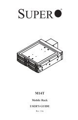
Motherboard Layout<br />
LE2<br />
SW1<br />
UID<br />
VGA<br />
LAN2/4<br />
LAN1/3 USB 2/3 USB 0/1<br />
FAN6<br />
COM1<br />
JPG1<br />
J21<br />
JBMC1<br />
JSTBY1<br />
COM2<br />
LEM1<br />
CPU1 Slot1 PCI-E 3.0 x16<br />
BMC<br />
CTRL<br />
CPU1 Slot2 PCI-E 3.0 x4 (in X8 slot)<br />
CPU1 Slot3 PCI-E 3.0 x16<br />
JPB1<br />
CPU2 Slot4 PCI-E 3.0 x16<br />
JP7<br />
JP6<br />
LAN<br />
CTRL<br />
CPU2 Slot5 PCI-E 3.0 x16<br />
JPL1<br />
CPU2 Slot6 PCI-E 3.0 x8<br />
P2 DIMMF3<br />
P2 DIMMF2<br />
P2 DIMMF1<br />
P2 DIMME3<br />
P2 DIMME2<br />
P2 DIMME1<br />
Alaways populate DIMMx1 first<br />
CPU2<br />
IPMI_LAN<br />
P2 DIMMG1<br />
P2 DIMMG2<br />
P2 DIMMG3<br />
P2 DIMMH1<br />
P2 DIMMH2<br />
P2 DIMMH3<br />
FAN5<br />
PHY<br />
JI2C2<br />
JI2C1<br />
SAS<br />
CTRL<br />
JTPM1<br />
JL1<br />
USB9<br />
JBT1<br />
BIOS BOX<br />
XDP-CPU<br />
JBAT1<br />
<strong>X9DR3</strong>-<strong>LN4F+</strong>/X9DRi-<strong>LN4F+</strong><br />
Rev. 1.10<br />
JPI2C1<br />
XDP-PCH<br />
JRK1<br />
BIOS<br />
I-SATA5 I-SATA3 I-SATA1<br />
JWD1<br />
USB6/7 USB4/5<br />
I-SATA4 JPME1 I-SATA2 I-SATA0<br />
IPMB JPME2<br />
J17<br />
J18<br />
JSD1<br />
SAS4~7<br />
PCH<br />
JWP1<br />
SAS0~3<br />
FANB<br />
FANA<br />
JOH1<br />
JD1<br />
SP1<br />
JF2<br />
FAN4<br />
Alaways populate DIMMx1 first<br />
P1 DIMMD3<br />
P1 DIMMD2<br />
P1 DIMMD1<br />
P1 DIMMC3<br />
P1 DIMMC2<br />
P1 DIMMC1<br />
FAN3<br />
JF1<br />
LE1<br />
CPU1<br />
P1 DIMMA1<br />
P1 DIMMA2<br />
P1 DIMMA3<br />
P1 DIMMB1<br />
P1 DIMMB2<br />
P1 DIMMB3<br />
FAN2<br />
JPW3 JPW2 JPW1<br />
FAN1<br />
Note: For the latest CPU/Memory updates, please refer to our website at<br />
http://www.supermicro.com/products/motherboard/ for details.<br />
1-3
1<br />
1<br />
<strong>X9DR3</strong>-<strong>LN4F+</strong>/X9DRi-<strong>LN4F+</strong> Motherboard User’s Manual<br />
<strong>X9DR3</strong>-<strong>LN4F+</strong>/X9DRi-<strong>LN4F+</strong> Quick Reference<br />
LE2<br />
SW1<br />
UID<br />
VGA<br />
LAN2/4<br />
LAN1/3 USB 2/3 USB 0/1<br />
FAN6<br />
COM1<br />
JPG1<br />
J21<br />
JBMC1<br />
JSTBY1<br />
COM2<br />
LEM1<br />
CPU1 Slot1 PCI-E 3.0 x16<br />
BMC<br />
CTRL<br />
CPU1 Slot2 PCI-E 3.0 x4 (in X8 slot)<br />
CPU1 Slot3 PCI-E 3.0 x16<br />
JPB1<br />
CPU2 Slot4 PCI-E 3.0 x16<br />
JP7<br />
JP6<br />
LAN<br />
CTRL<br />
CPU2 Slot5 PCI-E 3.0 x16<br />
JPL1<br />
CPU2 Slot6 PCI-E 3.0 x8<br />
P2 DIMMF3<br />
P2 DIMMF2<br />
P2 DIMMF1<br />
P2 DIMME3<br />
P2 DIMME2<br />
P2 DIMME1<br />
Alaways populate DIMMx1 first<br />
CPU2<br />
IPMI_LAN<br />
P2 DIMMG1<br />
P2 DIMMG2<br />
P2 DIMMG3<br />
P2 DIMMH1<br />
P2 DIMMH2<br />
P2 DIMMH3<br />
FAN5<br />
PHY<br />
JI2C2<br />
JI2C1<br />
SAS<br />
CTRL<br />
JTPM1<br />
JL1<br />
USB9<br />
JBT1<br />
BIOS BOX<br />
XDP-CPU<br />
JBAT1<br />
<strong>X9DR3</strong>-<strong>LN4F+</strong>/X9DRi-<strong>LN4F+</strong><br />
Rev. 1.10<br />
JPI2C1<br />
XDP-PCH<br />
JRK1<br />
BIOS<br />
I-SATA5 I-SATA3 I-SATA1<br />
JWD1<br />
USB6/7 USB4/5<br />
I-SATA4 JPME1 I-SATA2 I-SATA0<br />
IPMB JPME2<br />
J17<br />
J18<br />
JSD1<br />
SAS4~7<br />
PCH<br />
JWP1<br />
SAS0~3<br />
FANB<br />
FANA<br />
JOH1<br />
JD1<br />
SP1<br />
JF2<br />
FAN4<br />
Alaways populate DIMMx1 first<br />
P1 DIMMD3<br />
P1 DIMMD2<br />
P1 DIMMD1<br />
P1 DIMMC3<br />
P1 DIMMC2<br />
P1 DIMMC1<br />
FAN3<br />
JF1<br />
LE1<br />
CPU1<br />
P1 DIMMA1<br />
P1 DIMMA2<br />
P1 DIMMA3<br />
P1 DIMMB1<br />
P1 DIMMB2<br />
P1 DIMMB3<br />
FAN2<br />
JPW3 JPW2 JPW1<br />
FAN1<br />
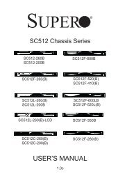
Notes:<br />
• See Chapter 3 for detailed information on jumpers, I/O ports and JF1 front panel<br />
connections.<br />
• " " indicates the location of "Pin 1".<br />
• Jumpers/LED Indicators not indicated are for testing only. Also, components that<br />
are not documented in this manual are reserved for internal use only.<br />
• Use only the correct type of onboard CMOS battery as specified by the manufacturer.<br />
Do not install the onboard battery upside down to avoid possible explosion.<br />
1-4
Chapter 1: Overview<br />
<strong>X9DR3</strong>-<strong>LN4F+</strong>/X9DRi-<strong>LN4F+</strong> Jumpers<br />
Jumper Description Default Setting<br />
JBT1 Clear CMOS See Chapter 2<br />
JI 2 C1/JI 2 C2 SMB to PCI-E Slots Pins 2-3 (Normal)<br />
JPB1 BMC Enabled Pins 1-2 (Enabled)<br />
JPG1 VGA Enabled Pins 1-2 (Enabled)<br />
JPL1 GLAN1/GLAN2 Enable Pins 1-2 (Enabled)<br />
JPME1<br />
JPME2<br />
Management Engine (ME)<br />
Recovery Mode Enable<br />
Management Engine (ME)<br />
Manufacture Select<br />
Pins 1-2 (Normal)<br />
Pins 1-2 (Normal)<br />
JWD Watch Dog Pins 1-2 (Reset)<br />
<strong>X9DR3</strong>-<strong>LN4F+</strong>/X9DRi-<strong>LN4F+</strong> Connectors<br />
Connectors<br />
COM1/COM2<br />
CPU1 Slot1/Slot3<br />
CPU2 Slot4/Slot5<br />
CPU2 Slot6<br />
CPU1 Slot2<br />
FAN1~6, FANA,<br />
FANB<br />
IPMB<br />
Description<br />
Backplane COM Port1/Front Accessible COM2 Header<br />
PCI-E 3.0 x16 Slots<br />
PCI-E 3.0 x8 Slot<br />
PCI-E 3.0 x4 in x8 Slot<br />
CPU/System Fan Headers<br />
4-pin External BMC I 2 C Header (for an IPMI Card)<br />
I-SATA 0~5 Intel SB SATA Connectors 0~5<br />
J17/J18 Serial-Link General_Purpose IO Headers (T-SGPIO 1/2)<br />
JBAT1<br />
JD1<br />
JF1<br />
JPI 2 C1<br />
JL1<br />
JOH1<br />
JPI 2 C1<br />
Onboard CMOS Battery (See Chapter 3 for Used Battery Disposal)<br />
Speaker/Power LED Indicator<br />
Front Panel Control Header<br />
System Management SMBbus I 2 C Header<br />
Chassis Intrusion<br />
Overheat/Fan Fail LED<br />
Power Supply SMBbus I 2 C Header<br />
JPW1 ATX 24-Pin Power Connector (See Warning on Page 1-6.)<br />
JPW2/JPW3 12V 8-Pin Power Connectors (See Warning on Page 1-6.)<br />
JSD1<br />
JSTBY1<br />
SATA DOM (Device_On_Module) Power Connector<br />
Standby Header<br />
JTPM1 TPM (Trusted Platform Module)/Port 80<br />
1-5
<strong>X9DR3</strong>-<strong>LN4F+</strong>/X9DRi-<strong>LN4F+</strong> Motherboard User’s Manual<br />
KB/Mouse<br />
PS2 Keyboard/Mouse<br />
LAN1/3, LAN2/4 G-bit Ethernet Ports 1/3, 2/4<br />
(IPMI) LAN<br />
IPMI_Dedicated LAN<br />
SP1<br />
Onboard Buzzer (Internal Speaker)<br />
USB 0/1 Back Panel USB 0/1<br />
USB 2/3 Back Panel USB 2/3<br />
USB 4/5, USB 6/7 Front Panel Accessible USB Connections 4/5, 6/7<br />
USB 9<br />
Front Panel Type A USB 9 Port<br />
UID Switch<br />
UID (Unit Identifier) Switch<br />
VGA<br />
Backpanel VGA Port<br />
<strong>X9DR3</strong>-<strong>LN4F+</strong>/X9DRi-<strong>LN4F+</strong> LED Indicators<br />
LED Description State Status<br />
LE1 Standby PWR LED Green: On SB Power On<br />
LE2 UID LED Blue Unit Identified<br />
LEM1 BMC Heartbeat LED Green: Blinking Normal<br />
Warning: To prevent damage to the power supply or motherboard, please use a power<br />
supply that contains a 24-pin and two 8-pin power connectors. Be sure to connect<br />
these power supply connectors to the 24-pin power connector (JPW1) and two 8-pin<br />
power connectors (JPW2, JPW3) on the motherboard. Failure in doing so will void the<br />
manufacturer warranty on your power supply and motherboard.<br />
1-6
Chapter 1: Overview<br />
Motherboard Features<br />
CPU<br />
Memory<br />
Chipset<br />
(RDIMM) or 128 GB of Unbuffered (UDIMM) ECC/Non-<br />
Expansion<br />
Slots<br />
Graphics<br />
Network<br />
I/O Devices<br />
• Dual Intel ® E5-2600(v2) Series Processors (Socket R<br />
LGA 2011); each processor supports four full-width Intel<br />
QuickPath Interconnect (QPI) links (with support of up to<br />
25.6 GT/s per QPI link and with Data Transfer Rate of up<br />
to 8.0 GT/s per direction).<br />
Note: For E5-2600(v2) processor support, BIOS<br />
version 3.0 or above is required.<br />
• Integrated memory controller supports up to 1.5 TB<br />
of Load Reduced (LRDIMM), 768 Gb of Registered<br />
ECC DDR3 800/1066/1333/1600/1866 MHz 240-pin<br />
4-channel memory in 24 DIMM slots.<br />
Note 1: 1866 MHz memory support is dependent<br />
on Intel E5-2600v2 CPUs.<br />
Note 2: For the latest memory updates, please<br />
refer to the Tested Memory List posted on our<br />
website (http://www.supermicro.com/products/<br />
motherboard).<br />
• Virtualization: VT-x, VT-d, and VT-c<br />
• Intel® C606/C602 Chipset<br />
• Four (4) PCI Express 3.0 x16 slots (CPU1 Slot1/Slot3,<br />
CPU2 Slot4/Slot5)<br />
• One (1) PCI Express 3.0 x8 slot (CPU2 Slot6)<br />
• One (1) PCI Express 3.0x4 in x8 slot (CPU1 Slot2)<br />
• Winbond Matrox MGA 200 Video Controller<br />
• One Intel i350A Gigabit (100/1000 Mb/s) Ethernet Quad/<br />
Dual-Channel Controller for LAN1~LAN4 ports.<br />
• Winbond WPCM450R Baseboard Controller (BMC) supports<br />
IPMI_LAN 2.0<br />
SATA Connections<br />
• SATA Ports Six (6): Two (2) SATA 3.0, Four (4)<br />
• RAID<br />
SATA 2.0 Ports<br />
Four (4) SATA 2.0 Ports from SCU<br />
(X9DRi-<strong>LN4F+</strong>)<br />
RAID 0, 1, 5, 10 (Windows)<br />
RAID 0, 1, 5, 10 (Linux)<br />
1-7
<strong>X9DR3</strong>-<strong>LN4F+</strong>/X9DRi-<strong>LN4F+</strong> Motherboard User’s Manual<br />
SCU Connections<br />
• SCU SAS/<br />
SATA2 Ports<br />
• RAID<br />
0~3, 4~7 (<strong>X9DR3</strong>-<strong>LN4F+</strong> Only)<br />
RAID 0, 1, 10 (Windows/Linux)<br />
Integrated IPMI 2.0<br />
• IPMI 2.0 supported by the Winbond WPCM 450R<br />
BMC<br />
Serial (COM) Port<br />
• Two (2) Fast UART 16550 Connection: 9-pin RS-<br />
232 port<br />
Keyboard/Mouse<br />
• Backplane USB Keyboard/Mouse<br />
VGA<br />
• Backplane VGA Port<br />
Peripheral<br />
Devices<br />
BIOS<br />
USB Devices<br />
• Four (4) USB ports on the rear I/O panel (USB 0/1,<br />
USB 2/3),<br />
• Four (4) USB connections for front access (USB<br />
4/5, USB 6/7),<br />
• One (1) Type A USB connector for front access<br />
(USB 9)<br />
• 16MB AMI Flash ROM<br />
• APM 1.2, DMI 2.3, PCI 2.3, ACPI 1.0/2.0/3.0, USB<br />
Keyboard, Plug & Play (PnP) and SMBIOS 2.3<br />
Power<br />
Config.<br />
• ACPI/ACPM Power Management<br />
• Main switch override mechanism<br />
• Keyboard Wake-up from Soft-Off<br />
• Power-on mode for AC power recovery<br />
• Intel ® Intelligent Power Node Manager (NM) (Available<br />
when the NMView utility is installed in the<br />
system)<br />
• Management Engine (ME)<br />
PC Health<br />
Monitoring<br />
CPU Monitoring<br />
• Onboard voltage monitors for 1.8V, +3.3V, 3.3VSB,<br />
+5V Standby, 1.35V, 1.5V, Chipset Voltage, and<br />
Battery Voltage.<br />
• CPU 6-Phase switching voltage regulator<br />
1-8
Chapter 1: Overview<br />
• CPU/System overheat LED and control<br />
• CPU Thermal Trip support<br />
• Thermal Monitor 2 (TM2) support<br />
Fan Control<br />
• Fan status monitoring with firmware thermal management<br />
via IPMI 2.0<br />
• Low noise fan speed control<br />
LED Indicators<br />
• System/CPU Overheat LED<br />
• Suspend-state LED<br />
• UID/Remote UID LED<br />
System<br />
Management<br />
• PECI (Platform Environment Configuration Interface)<br />
2.0 support<br />
• System resource alert via SuperDoctor® III<br />
• Thermal Monitor 2 (TM2) support<br />
• SuperDoctor® III, Watch Dog, NMI<br />
• Chassis Intrusion Header and Detection<br />
Dimensions<br />
• 13.68" (L) x 13.05" (W) (347.47 mm x 331.47 mm)<br />
Note 1: For IPMI Configuration Instructions, please refer to the Embedded<br />
IPMI Configuration User's Guide available @ http://www.supermicro.com/<br />
support/manuals/.<br />
Note 2: Changing BMC log-in information is recommended during initial<br />
system power-on. The default username is ADMIN and password is ADMIN.<br />
For BMC best practices, please refer to: http://www.supermicro.com/products/<br />
nfo/files/IPMI/Best_Practices_BMC_Security.pdf<br />
1-9
<strong>X9DR3</strong>-<strong>LN4F+</strong>/X9DRi-<strong>LN4F+</strong> Motherboard User’s Manual<br />
A #1<br />
B #2<br />
C #3<br />
DDR3 DIMM<br />
A #1<br />
B #2<br />
C #3<br />
DDR3 DIMM<br />
E<br />
#1<br />
PCI-E x16 Slot<br />
#4<br />
PCI-E x16 Slot<br />
A #1<br />
B #2<br />
C #3<br />
C<br />
DDR3 DIMM<br />
A #1<br />
B #2<br />
C #3<br />
DDR3 DIMM<br />
#2<br />
x16<br />
PCI-E x8 Slot<br />
#5<br />
PCI-E x16 Slot<br />
x4<br />
F<br />
D<br />
PCI-E x16 Slot<br />
#6<br />
PCI-E x16 Slot<br />
PE3 PE2 PE1<br />
CPU REAR<br />
Socket 2<br />
PROCESSOR<br />
P0 P1<br />
QPI<br />
P1<br />
CPU FRONT<br />
Socket 1<br />
PROCESSOR<br />
RJ45 RJ45<br />
RJ45 RJ45<br />
QPI<br />
P0<br />
DMI<br />
PE3 PE2 PE1 DMI<br />
#3<br />
x16<br />
x16<br />
x4 [7.4]<br />
x4<br />
LAN<br />
H<br />
[3.0]<br />
x4<br />
#1 A<br />
#2 B<br />
#3 C<br />
DDR3 DIMM<br />
B<br />
DDR3 DIMM<br />
SYSTEM<br />
BIOS<br />
DMI<br />
PEG0<br />
G<br />
#1 A<br />
#2 B<br />
#3 C<br />
SPI<br />
PEG1 [4:1]<br />
PEG1_8<br />
x1<br />
#1 A<br />
#2 B<br />
#3 C<br />
DDR3 DIMM<br />
A<br />
#1 A<br />
#2 B<br />
#3 C<br />
SSB<br />
DDR3 DIMM<br />
Intel C606/C602<br />
LPC<br />
SATA<br />
#1~#6<br />
SATA<br />
(4 SATA2 for X9DRi<br />
-<strong>LN4F+</strong> Only)<br />
(For <strong>X9DR3</strong><br />
-<strong>LN4F+</strong> Only)<br />
USB<br />
USB<br />
0,1<br />
2,3<br />
SCU<br />
#1~#8<br />
HDR 2X5<br />
TYPE-A<br />
HDR 2X5<br />
REAR REAR 4,5 9 6, 7<br />
DDR III<br />
BMC VGA<br />
TPM HDR<br />
VGA CONN<br />
PHY1<br />
RTL8211<br />
LAN<br />
SIO<br />
W83527<br />
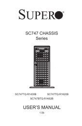
System Block Diagram<br />
Note: This is a general block diagram and may not exactly represent the<br />
features on your motherboard. See the Motherboard Features pages for<br />
the actual specifications of each motherboard. 2. This block diagram is<br />
intended for your reference only.<br />
1-10
Chapter 1: Overview<br />
1-2 Processor and Chipset Overview<br />
Built upon the functionality and the capability of the Intel E5-2600(v2) Series<br />
Processors (Socket R LGA 2011) and the C606/C602 chipset, the <strong>X9DR3</strong>-<strong>LN4F+</strong>/<br />
X9DRi-<strong>LN4F+</strong> motherboard provides the performance and feature sets required<br />
for dual_processor-based HPC/Cluster/Database servers.<br />
With support of Intel QuickPath interconnect (QPI) Technology, the <strong>X9DR3</strong>-<strong>LN4F+</strong>/<br />
X9DRi-<strong>LN4F+</strong> offers point-to-point serial interconnect interface with a transfer<br />
speed of up to 8.0 GT/s, providing superb system performance.<br />
The C606/C602 chipset provides extensive IO support, including the following<br />
functions and capabilities:<br />
• PCI-Express Rev. 2.0 support<br />
• PCI-Express Gen. 3 uplink supported by some SKUs<br />
• ACPI Power Management Logic Support Rev. 3.0b or Rev. 4.0<br />
• USB host interface backplane and front access support<br />
• Intel Rapid Storage Technology supported<br />
• Intel Virtualization Technology for Directed I/O (Intel VT-d) supported<br />
• Intel Trusted Execution Technology supported<br />
• Serial Peripheral Interface (SPI) Supported<br />
• Digital Media Interface (DMI) supported<br />
• Advanced Host Controller Interface (AHCI) supported<br />
Note: For Intel E5-2600(v2) processor support, BIOS version 3.0 or above<br />
is required.<br />
1-11
<strong>X9DR3</strong>-<strong>LN4F+</strong>/X9DRi-<strong>LN4F+</strong> Motherboard User’s Manual<br />
1-3 Special Features<br />
Recovery from AC Power Loss<br />
The Basic I/O System (BIOS) provides a setting that determines how the system will<br />
respond when AC power is lost and then restored to the system. You can choose for<br />
the system to remain powered off (in which case you must press the power switch<br />
to turn it back on), or for it to automatically return to the power-on state. See the<br />
Advanced BIOS Setup section for this setting. The default setting is Last State.<br />
1-4 PC Health Monitoring<br />
This section describes the features of PC health monitoring of the motherboard.<br />
This motherboard has an onboard System_Hardware_Monitor chip that supports PC<br />
health monitoring. An onboard voltage monitor will scan the voltages for processor,<br />
memory, chipset, and battery continuously. Once a voltage becomes unstable, a<br />
warning is given, or an error message is sent to the screen. The user can adjust<br />
the voltage thresholds to define the sensitivity of the voltage monitor.<br />
Fan Status Monitor with Firmware Control<br />
The PC health monitor chip can check the RPM status of a cooling fan. The onboard<br />
CPU and chassis fans are controlled by firmware thermal management via IPMI 2.0.<br />
Environmental Temperature Control<br />
A thermal control sensor monitors the CPU temperature in real time and will turn<br />
on the thermal control fan whenever the CPU temperature exceeds a user-defined<br />
threshold. The overheat circuitry runs independently from the CPU. Once the<br />
thermal management firmware detects that the CPU temperature is too high, it will<br />
automatically turn on the thermal fan control to prevent the CPU from overheating.<br />
The onboard chassis thermal circuitry can monitor the overall system temperature<br />
and alert the user when the chassis temperature is too high.<br />
Note: To avoid possible system overheating, please be sure to provide<br />
adequate airflow to your system.<br />
System Resource Alert<br />
This feature is available when used with SuperDoctor® III in the Windows OS<br />
environment or used with SuperDoctor II in Linux. SuperDoctor is used to notify<br />
the user of certain system events. For example, you can configure SuperDoctor<br />
to provide you with warnings when the system temperature, CPU temperatures,<br />
1-12
Chapter 1: Overview<br />
voltages and fan speeds go beyond a predefined range.<br />
1-5 ACPI Features<br />
ACPI stands for Advanced Configuration and Power Interface. The ACPI specification<br />
defines a flexible and abstract hardware interface that provides a standard<br />
way to integrate power management features throughout a PC system, including<br />
its hardware, operating system and application software. This enables the system<br />
to automatically turn on and off peripherals such as CD-ROMs, network cards, hard<br />
disk drives and printers.<br />
In addition to enabling operating_system-directed power management, ACPI also<br />
provides a generic system event mechanism for Plug and Play, and an operating<br />
system-independent interface for configuration control. ACPI leverages the Plug and<br />
Play BIOS data structures, while providing a processor architecture-independent<br />
implementation that is compatible with Windows 7, Windows Vista and Windows<br />
2008 Operating Systems.<br />
Slow Blinking LED for Suspend-State Indicator<br />
When the CPU goes into a suspend state, the chassis power LED will start blinking<br />
to indicate that the CPU is in suspend mode. When the user presses any key, the<br />
CPU will "wake up" and the LED will automatically stop blinking and remain on.<br />
1-6 Power Supply<br />
As with all computer products, a stable power source is necessary for proper and<br />
reliable operation. It is even more important for processors that have high CPU<br />
clock rates.<br />
The <strong>X9DR3</strong>-<strong>LN4F+</strong>/X9DRi-<strong>LN4F+</strong> motherboard accommodates 24-pin ATX power<br />
supplies. Although most power supplies generally meet the specifications required<br />
by the CPU, some are inadequate. In addition, two 12V 8-pin power connections are<br />
also required to ensure adequate power supply to the system. Your power supply<br />
must also supply 1.5A for the Ethernet ports.<br />
Warning: To prevent damage to the power supply or motherboard, please use a power<br />
supply that contains a 24-pin and two 8-pin power connectors. Be sure to connect these<br />
power supply connectors to the 24-pin (JPW1) and two 8-pin power connectors (JPW2,<br />
JPW3) on the motherboard. Failure to do so will void the manufacturer warranty on<br />
your power supply and motherboard.<br />
It is strongly recommended that you use a high quality power supply that meets ATX<br />
power supply Specification 2.02 or above. It must also be SSI compliant. (For more<br />
information, please refer to the website at http://www.ssiforum.org/). Additionally, in<br />
1-13
<strong>X9DR3</strong>-<strong>LN4F+</strong>/X9DRi-<strong>LN4F+</strong> Motherboard User’s Manual<br />
areas where noisy power transmission is present, you may choose to install a line<br />
filter to shield the computer from noise. It is recommended that you also install a<br />
power surge protector to help avoid problems caused by power surges.<br />
1-7 Super I/O<br />
The Super I/O supports two high-speed, 16550 compatible serial communication<br />
ports (UARTs). Each UART includes a 16-byte send/receive FIFO, a programmable<br />
baud rate generator, complete modem control capability and a processor interrupt<br />
system. Both UARTs provide legacy speed with baud rate of up to 115.2 Kbps<br />
as well as an advanced speed with baud rates of 250 K, 500 K, or 1 Mb/s, which<br />
support higher speed modems.<br />
The Super I/O provides functions that comply with ACPI (Advanced Configuration<br />
and Power Interface), which includes support of legacy and ACPI power management<br />
through an SMI or SCI function pin. It also features auto power management<br />
to reduce power consumption.<br />
1-8 Advanced Power Management<br />
The following advanced power management features are supported by this motherboard:<br />
Intel ® Intelligent Power Node Manager (NM) (Available<br />
when the NMView utility is installed in the system)<br />
The Intel ® Intelligent Power Node Manager (IPNM) provides your system with<br />
real-time thermal control and power management for maximum energy efficiency.<br />
Although IPNM Specification Version 1.5/2.0 is supported by the BMC (Baseboard<br />
Management Controller), your system must also have IPNM-compatible Management<br />
Engine (ME) firmware installed to use this feature.<br />
Note: Support for IPNM Specification Version 1.5 or Vision 2.0 depends<br />
on the power supply used in the system.<br />
Management Engine (ME)<br />
The Management Engine, which is an ARC controller embedded in the PCH, provides<br />
Server Platform Services (SPS) to your system. The services provided by<br />
SPS are different from those provided by the ME on client platforms.<br />
1-14
Chapter 1: Overview<br />
1-9 Overview of the Nuvoton WPCM450 Controller<br />
The Nuvoton WPCM450R Controller, a Baseboard Management Controller (BMC),<br />
supports 2D/VGA-compatible Graphic Cores with PCI interface, creating multi-media<br />
virtualization via Keyboard/Video/Mouse Redirection (KVMR). The WPCM450R<br />
Controller is ideal for remote system management.<br />
The WPCM450R Controller interfaces with the host system via PCI connections<br />
to communicate with the graphics cores. It supports USB 2.0 and 1.1 for remote<br />
keyboard/mouse/virtual media emulation. It also provides LPC interface support to<br />
control Super IO functions. The WPCM450R Controller is connected to the network<br />
via an external Ethernet PHY module or shared NCSI connections.<br />
The WPCM450R communicates with onboard components via six SMBus interfaces,<br />
PECI (Platform Environment Control Interface) buses, and General Purpose<br />
I/O ports.<br />
Other Features Supported by the WPCM BMC Controller<br />
The WPCM450R supports the following features:<br />
• IPMI 2.0<br />
• Serial over LAN<br />
• KVM over LAN<br />
• LAN Alerting-SNMP Trap<br />
• Event Log<br />
• X-Bus parallel interface for I/O expansion<br />
• Multiple ADC inputs, Analog and Digital Video outputs<br />
• SPI Flash Host BIOS and firmware bootstrap program supported<br />
• Reduced Media Independent Interface (RMII)<br />
• OS (Operating System) Independency<br />
• Provides remote Hardware Health Monitoring via IPMI. Key features<br />
1-15
<strong>X9DR3</strong>-<strong>LN4F+</strong>/X9DRi-<strong>LN4F+</strong> Motherboard User’s Manual<br />
• Provides Network Management Security via remote access/console redirection.<br />
• Supports the following Management tools: IPMIView, CLI (Command Line<br />
Interface)<br />
• RMCP+ protocol supported<br />
Note 1: For more information on IPMI configuration, please refer to the<br />
IPMI User's Guide posted on our website at http://www.supermicro.com/<br />
support/manuals/.<br />
Note 2: The term "IPMI controller" and the term "BMC controller" can be<br />
used interchangeably in this section.<br />
1-16
Chapter 2: Installation<br />
Chapter 2<br />
Installation<br />
2-1 Standardized Warning Statements<br />
The following statements are industry-standard warnings, provided to warn the user<br />
of situations which have the potential for bodily injury. Should you have questions or<br />
experience difficulty, contact <strong>Supermicro</strong>'s Technical Support department for assistance.<br />
Only certified technicians should attempt to install or configure components.<br />
Read this section in its entirety before installing or configuring components in the<br />
<strong>Supermicro</strong> chassis.<br />
Battery Handling<br />
Warning!<br />
There is a danger of explosion if the battery is replaced incorrectly. Replace the<br />
battery only with the same or equivalent type recommended by the manufacturer.<br />
Dispose of used batteries according to the manufacturer's instructions<br />
電 池 の 取 り 扱 い<br />
電 池 交 換 が 正 しく 行 われなかった 場 合 、 破 裂 の 危 険 性 があります。 交 換 する 電 池 はメー<br />
カーが 推 奨 する 型 、または 同 等 のものを 使 用 下 さい。 使 用 済 電 池 は 製 造 元 の 指 示 に 従<br />
って 処 分 して 下 さい。<br />
警 告<br />
电 池 更 换 不 当 会 有 爆 炸 危 险 。 请 只 使 用 同 类 电 池 或 制 造 商 推 荐 的 功 能 相 当 的 电 池 更<br />
换 原 有 电 池 。 请 按 制 造 商 的 说 明 处 理 废 旧 电 池 。<br />
警 告<br />
電 池 更 換 不 當 會 有 爆 炸 危 險 。 請 使 用 製 造 商 建 議 之 相 同 或 功 能 相 當 的 電 池 更 換 原 有<br />
電 池 。 請 按 照 製 造 商 的 說 明 指 示 處 理 廢 棄 舊 電 池 。<br />
Warnung<br />
Bei Einsetzen einer falschen Batterie besteht Explosionsgefahr. Ersetzen Sie die<br />
Batterie nur durch den gleichen oder vom Hersteller empfohlenen Batterietyp.<br />
Entsorgen Sie die benutzten Batterien nach den Anweisungen des Herstellers.<br />
2-1
<strong>X9DR3</strong>-<strong>LN4F+</strong>/X9DRi-<strong>LN4F+</strong> Motherboard User’s Manual<br />
Attention<br />
Danger d'explosion si la pile n'est pas remplacée correctement. Ne la remplacer<br />
que par une pile de type semblable ou équivalent, recommandée par le fabricant.<br />
Jeter les piles usagées conformément aux instructions du fabricant.<br />
¡Advertencia!<br />
Existe peligro de explosión si la batería se reemplaza de manera incorrecta. Reemplazar<br />
la batería exclusivamente con el mismo tipo o el equivalente recomendado<br />
por el fabricante. Desechar las baterías gastadas según las instrucciones<br />
del fabricante.<br />
אזהרה!<br />
קיימת סכנת פיצוץ של הסוללה במידה והוחלפה בדרך לא תקינה. יש להחליף<br />
את הסוללה בסוג התואם מחברת יצרן מומלצת.<br />
סילוק הסוללות המשומשות יש לבצע לפי הוראות היצרן.<br />
هناك خطر من انفجار في حالة اسحبذال البطارية بطريقة غير صحيحة فعليل<br />
اسحبذال البطارية<br />
فقط بنفس النىع أو ما يعادلها مما أوصث به الشرمة المصنعة<br />
جخلص من البطاريات المسحعملة وفقا ل حعليمات الشرمة الصانعة<br />
경고!<br />
배터리가 올바르게 교체되지 않으면 폭발의 위험이 있습니다. 기존 배터리와 동일<br />
하거나 제조사에서 권장하는 동등한 종류의 배터리로만 교체해야 합니다. 제조사<br />
의 안내에 따라 사용된 배터리를 처리하여 주십시오.<br />
Waarschuwing<br />
Er is ontploffingsgevaar indien de batterij verkeerd vervangen wordt. Vervang de<br />
batterij slechts met hetzelfde of een equivalent type die door de fabrikant aanbevolen<br />
wordt. Gebruikte batterijen dienen overeenkomstig fabrieksvoorschriften<br />
afgevoerd te worden.<br />
2-2
Chapter 2: Installation<br />
Product Disposal<br />
Warning!<br />
Ultimate disposal of this product should be handled according to all national laws<br />
and regulations.<br />
製 品 の 廃 棄<br />
この 製 品 を 廃 棄 処 分 する 場 合 、 国 の 関 係 する 全 ての 法 律 ・ 条 例 に 従 い 処 理 する 必 要 が<br />
あります。<br />
警 告<br />
本 产 品 的 废 弃 处 理 应 根 据 所 有 国 家 的 法 律 和 规 章 进 行 。<br />
警 告<br />
本 產 品 的 廢 棄 處 理 應 根 據 所 有 國 家 的 法 律 和 規 章 進 行 。<br />
Warnung<br />
Die Entsorgung dieses Produkts sollte gemäß allen Bestimmungen und Gesetzen<br />
des Landes erfolgen.<br />
¡Advertencia!<br />
Al deshacerse por completo de este producto debe seguir todas las leyes y reglamentos<br />
nacionales.<br />
Attention<br />
La mise au rebut ou le recyclage de ce produit sont généralement soumis à des<br />
lois et/ou directives de respect de l'environnement. Renseignez-vous auprès de<br />
l'organisme compétent.<br />
2-3
<strong>X9DR3</strong>-<strong>LN4F+</strong>/X9DRi-<strong>LN4F+</strong> Motherboard User’s Manual<br />
2-2 Static-Sensitive Devices<br />
Electrostatic Discharge (ESD) can damage electronic com ponents. To avoid damaging<br />
your system board, it is important to handle it very carefully. The following<br />
measures are generally sufficient to protect your equipment from ESD.<br />
Precautions<br />
• Use a grounded wrist strap designed to prevent static discharge.<br />
• Touch a grounded metal object before removing the motherboard from the<br />
antistatic bag.<br />
• Handle the board by its edges only; do not touch its components, peripheral<br />
chips, memory modules or gold contacts.<br />
• When handling chips or modules, avoid touching their pins.<br />
• Put the motherboard and peripherals back into their antistatic bags when not<br />
in use.<br />
• For grounding purposes, make sure that your system chassis provides excellent<br />
conductivity between the power supply, the case, the mounting fasteners and<br />
the motherboard.<br />
Unpacking<br />
The motherboard is shipped in antistatic packaging to avoid static damage. When<br />
unpacking the board, make sure that the person handling it is static protected.<br />
2-4
OPEN 1st<br />
OPEN 1st<br />
Chapter 2: Installation<br />
2-3 Processor and Heatsink Installation<br />
Warning: When handling the processor package, avoid placing direct pressure on<br />
the label area.<br />
Notes:<br />
• Always connect the power cord last, and always remove it before adding,<br />
removing or changing any hardware components. Make sure that you install<br />
the processor into the CPU socket before you install the CPU heatsink.<br />
• If you buy a CPU separately, make sure that you use an Intel-certified multidirectional<br />
heatsink only.<br />
• Make sure to install the system board into the chassis before you install<br />
the CPU heatsink.<br />
• When receiving a server board without a processor pre-installed, make sure<br />
that the plastic CPU socket cap is in place and none of the socket pins are<br />
bent; otherwise, contact your retailer immediately.<br />
• Refer to the <strong>Supermicro</strong> website for updates on CPU support.<br />
Installing the LGA2011 Processor<br />
1. There are two load levers on the LGA2011 socket. To open the socket cover,<br />
first press and release the load lever labeled 'Open 1st'.<br />
1 2<br />
WARNING!<br />
WARNING!<br />
Press down<br />
on Load Lever<br />
labeled 'Open 1st'.<br />
2-5
OPEN 1st<br />
OPEN 1st<br />
OPEN 1st<br />
<strong>X9DR3</strong>-<strong>LN4F+</strong>/X9DRi-<strong>LN4F+</strong> Motherboard User’s Manual<br />
2. Press the second load lever labeled 'Close 1st' to release the load plate that<br />
covers the CPU socket from its locking position.<br />
1 Press down on Load the 2<br />
Lever labeled 'Close 1st'<br />
Pull lever away from<br />
the socket<br />
WARNING!<br />
WARNING!<br />
1<br />
3. With the lever labeled 'Close 1st' fully retracted, gently push down on the<br />
'Open 1st' lever to open the load plate. Lift the load plate to open it completely.<br />
Gently push<br />
down to pop the<br />
load plate open.<br />
2<br />
WARNING!<br />
WARNING!<br />
2-6
WARNING!<br />
Chapter 2: Installation<br />
1. Using your thumb and the index finger, remove the 'WARNING' plastic cap<br />
from the socket.<br />
2. Use your thumb and index finger to hold the CPU on its edges. Align the CPU<br />
keys, which are semi-circle cutouts, against the socket keys.<br />
Socket Keys<br />
CPU Keys<br />
3. Once they are aligned, carefully lower the CPU straight down into the socket.<br />
(Do not drop the CPU on the socket. Do not move the CPU horizontally or<br />
vertically. Do not rub the CPU against the surface or against any pins of the<br />
socket to avoid damaging the CPU or the socket.)<br />
Warning: You can only install the<br />
CPU inside the socket in one direction.<br />
Make sure that it is properly<br />
inserted into the CPU socket before<br />
closing the load plate. If it doesn't<br />
close properly, do not force it as it<br />
may damage your CPU. Instead,<br />
open the load plate again and double-check<br />
that the CPU is aligned<br />
properly.<br />
2-7
<strong>X9DR3</strong>-<strong>LN4F+</strong>/X9DRi-<strong>LN4F+</strong> Motherboard User’s Manual<br />
4. With the CPU inside the socket, inspect the four corners of the CPU to make<br />
sure that the CPU is properly installed.<br />
5. Close the load plate with the CPU inside the socket. Lock the lever labeled<br />
'Close 1st' first, then lock the lever labeled 'Open 1st' second. Use your<br />
thumb to gently push the load levers down to the lever locks.<br />
1 2<br />
Gently close<br />
the load plate.<br />
Push down and lock the<br />
level labeled 'Close 1st'.<br />
OPEN 1st<br />
3 4<br />
Lever Lock<br />
Push down and<br />
lock the lever<br />
labeled 'Open 1st'<br />
OPEN 1st<br />
OPEN 1st<br />
Lever Lock<br />
2-8
Chapter 2: Installation<br />
Installing a Passive CPU Heatsink<br />
1. Do not apply any thermal grease to the heatsink or the CPU die -- the required<br />
amount has already been applied.<br />
2. Place the heatsink on top of the CPU so that the four mounting holes are<br />
aligned with those on the Motherboard's and the Heatsink Bracket underneath.<br />
3. Screw in two diagonal screws (i.e., the #1 and the #2 screws) until just snug<br />
(-do not over-tighten the screws to avoid possible damage to the CPU.)<br />
4. Finish the installation by fully tightening all four screws.<br />
Screw#4<br />
Screw#1<br />
Screw#2<br />
OPEN 1st<br />
Mounting Holes<br />
Motherboard<br />
Notes: 1. For optimized airflow, please follow your chassis airflow direction<br />
to install the correct CPU heatsink direction. 2. Graphic drawings<br />
included in this manual are for reference only. They might look different<br />
from the components installed in your system.<br />
2-9
<strong>X9DR3</strong>-<strong>LN4F+</strong>/X9DRi-<strong>LN4F+</strong> Motherboard User’s Manual<br />
Removing the Heatsink<br />
Warning: We do not recommend that the CPU or the heatsink be removed. However,<br />
if you do need to uninstall the heatsink, please follow the instructions below to uninstall<br />
the heatsink to prevent damage done to the CPU or the CPU socket.<br />
1. Unscrew the heatsink screws from the motherboard in the sequence as<br />
shown in the illustration below.<br />
2. Gently wriggle the heatsink to loosen it from the CPU. (Do not use excessive<br />
force when wriggling the heatsink!)<br />
3. Once the CPU is loosened, remove the CPU from the CPU socket.<br />
4. Remove the used thermal grease and clean the surface of the CPU and the<br />
heatsink, Reapply the proper amount of thermal grease on the surface before<br />
reinstalling the CPU and the heatsink. (Do not reuse old thermal grease!)<br />
Loosen screws in sequence as shown.<br />
Screw#4<br />
Screw#1<br />
Screw#2<br />
Screw#3<br />
Motherboard<br />
Warning: Do not reuse old thermal grease!<br />
2-10
J21<br />
JL1<br />
J17<br />
JI2C2<br />
JI2C1<br />
J18<br />
LEM1<br />
SAS4~7<br />
JWP1<br />
SAS0~3<br />
1<br />
XDP-CPU<br />
JD1<br />
JP7<br />
JP6<br />
JF2<br />
1<br />
LE2<br />
SW1<br />
UID<br />
VGA<br />
JF1<br />
LAN2/4<br />
LE1<br />
LAN1/3 USB 2/3 USB 0/1<br />
IPMI_LAN<br />
COM1<br />
FAN1<br />
Chapter 2: Installation<br />
2-4 Installing and Removing the Memory Modules<br />
Note: Check <strong>Supermicro</strong>'s website for recommended memory modules.<br />
CAUTION<br />
Exercise extreme care when installing or removing DIMM<br />
modules to prevent any possible damage.<br />
Installing & Removing DIMMs<br />
1. Insert the desired number of DIMMs into the memory slots, starting with<br />
P1-DIMMA1. (For best performance, please use the memory modules of the<br />
same type and speed in the same bank.)<br />
2. Push the release tabs outwards on both ends of the DIMM slot to unlock it.<br />
JBMC1 JSTBY1<br />
JPG1<br />
COM2<br />
CPU1 Slot1 PCI-E 3.0 x16<br />
BMC<br />
CTRL<br />
CPU1 Slot2 PCI-E 3.0 x4 (in X8 slot)<br />
CPU1 Slot3 PCI-E 3.0 x16<br />
JPB1<br />
CPU2 Slot4 PCI-E 3.0 x16<br />
LAN<br />
CTRL<br />
CPU2 Slot5 PCI-E 3.0 x16<br />
JPL1<br />
CPU2 Slot6 PCI-E 3.0 x8<br />
P2 DIMMF3<br />
P2 DIMMF2<br />
P2 DIMMF1<br />
P2 DIMME3<br />
P2 DIMME2<br />
P2 DIMME1<br />
Alaways populate DIMMx1 first<br />
CPU2<br />
FAN6<br />
P2 DIMMG1<br />
P2 DIMMG2<br />
P2 DIMMG3<br />
P2 DIMMH1<br />
P2 DIMMH2<br />
P2 DIMMH3<br />
FAN5<br />
PHY<br />
Notches<br />
SAS<br />
CTRL<br />
JTPM1<br />
USB9<br />
JBT1<br />
BIOS BOX<br />
JBAT1<br />
<strong>X9DR3</strong>-<strong>LN4F+</strong>/X9DRi-<strong>LN4F+</strong><br />
Rev. 1.10<br />
JPI2C1<br />
IPMB<br />
JPME2<br />
USB6/7<br />
USB4/5<br />
JWD1<br />
I-SATA5<br />
I-SATA4 JPME1<br />
I-SATA2<br />
I-SATA0<br />
I-SATA3<br />
I-SATA1<br />
JSD1<br />
XDP-PCH<br />
JRK1<br />
BIOS<br />
PCH<br />
FANB<br />
FANA<br />
JOH1<br />
SP1<br />
FAN4<br />
Alaways populate DIMMx1 first<br />
P1 DIMMC1<br />
FAN3<br />
P1 DIMMC3<br />
P1 DIMMC2<br />
P1 DIMMD3<br />
P1 DIMMD2<br />
P1 DIMMD1<br />
CPU1<br />
P1 DIMMA1<br />
P1 DIMMA2<br />
P1 DIMMA3<br />
P1 DIMMB1 FAN2<br />
P1 DIMMB2<br />
P1 DIMMB3<br />
JPW3 JPW2 JPW1<br />
Release Tabs<br />
3. Align the key of the DIMM module with the receptive point on the memory<br />
slot.<br />
4. Align the notches on both ends of the module against the receptive points on<br />
the ends of the slot.<br />
5. Use two thumbs together to press the notches on both ends of the module<br />
straight down into the slot until the module snaps into place.<br />
6. Press the release tabs to the locking positions to secure the DIMM module<br />
into the slot.<br />
Press both notches straight<br />
down into the memory slot at<br />
the same time.<br />
Removing Memory Modules<br />
Press both notches at the ends of a DIMM module to unlock it. Once it is loosened,<br />
remove the DIMM module from the motherboard.<br />
2-11
<strong>X9DR3</strong>-<strong>LN4F+</strong>/X9DRi-<strong>LN4F+</strong> Motherboard User’s Manual<br />
Memory Support for the <strong>X9DR3</strong>-<strong>LN4F+</strong>/X9DRi-<strong>LN4F+</strong><br />
Motherboard<br />
The <strong>X9DR3</strong>-<strong>LN4F+</strong>/X9DRi-<strong>LN4F+</strong> motherboard supports up to 1.5 TB of Load<br />
Reduced (LRDIMM), 768 Gb of Registered (RDIMM) or 128 GB of Unbuffered<br />
(UDIMM) ECC/Non-ECC DDR3 800/1066/1333/1600/1866 MHz of 240-pin 4-channel<br />
memory in 24 DIMM slots.<br />
Note: For the latest memory updates, please refer to the Tested Memory<br />
List posted on our website (http://www.supermicro.com/products/motherboard).<br />
Processor & Memory Module Population Configuration<br />
For memory to work properly, follow the tables below for memory installation.<br />
Processor and Memory Module Population<br />
Number of<br />
CPUs+DIMMs<br />
1 CPU &<br />
2 DIMMs<br />
1 CPU &<br />
4 DIMMs<br />
1 CPU &<br />
5~8 DIMMs<br />
1 CPU &<br />
9~12 DIMMs<br />
2 CPUs &<br />
4 DIMMs<br />
2 CPUs &<br />
6 DIMMs<br />
2 CPUs &<br />
8 DIMMs<br />
2 CPUs &<br />
9~12 DIMMs<br />
2 CPUs &<br />
13 DIMMs~24<br />
DIMMs<br />
CPU1<br />
P1-DIMMA1/P1-DIMMB1<br />
CPU and Memory Population Configuration Table<br />
CPU1<br />
P1-DIMMA1/P1-DIMMB1, P1-DIMMC1/P1-DIMMD1<br />
CPU1<br />
P1-DIMMA1/P1-DIMMB1, P1-DIMMC1/P1-DIMMD1, P1-DIMMA2/P1-DIMMB2, P1-DIMMC2/<br />
P1-DIMMD2<br />
CPU1<br />
P1-DIMMA1/P1-DIMMB1, P1-DIMMC1/P1-DIMMD1, P1-DIMMA2/P1-DIMMB2, P1-<br />
DIMMC2/P1-DIMMD2, P1-DIMMA3/P1-DIMMB3, P1-DIMMC3/P1-DIMMD3<br />
CPU1 + CPU2<br />
P1-DIMMA1/P1-DIMMB1, P2-DIMME1/P2-DIMMF1<br />
CPU1 + CPU2<br />
P1-DIMMA1/P1-DIMMB1, P2-DIMME1/P2-DIMMF1, P1-DIMMC1/P1-DIMMD1<br />
CPU1 + CPU2<br />
P1-DIMMA1/P1-DIMMB1, P2-DIMME1/P2-DIMMF1, P1-DIMMC1/P1-DIMMD1, P2-DIMMG1/<br />
P2-DIMMH1<br />
CPU1/CPU2<br />
P1-DIMMA1/P1-DIMMB1, P2-DIMME1/P2-DIMMF1, P1-DIMMC1/P1-DIMMD1, P2-DIMMG1/<br />
P2-DIMMH1, P1-DIMMA2/P1-DIMMB2, P2-DIMME2/P2-DIMMF2<br />
CPU1/CPU<br />
P1-DIMMA1/P1-DIMMB1, P2-DIMME1/P2-DIMMF1, P1-DIMMC1/P1-DIMMD1, P2-DIMMG1/<br />
P2-DIMMH1, P1-DIMMA2/P1-DIMMB2, P2-DIMME2/P2-DIMMF2,<br />
P1-DIMMC2/P1-DIMMD2, P2-DIMMG2/P2-DIMMH2, P1-DIMMA3/P1-DIMMB3, P2-DIMME3/<br />
P2-DIMMF3, P1-DIMMC3/P1-DIMMD3, P2-DIMMG3/P2-DIMMH3<br />
Note: 1866 MHz memory support is dependent on Intel E5-2600v2 CPUs.<br />
For Intel E5-2600(v2) processor support, BIOS version 3.0 or above is<br />
required.<br />
2-12
Chapter 2: Installation<br />
Populating UDIMM (ECC/Non-ECC) Memory Modules<br />
Intel E5-2600(v2) Series Processor UDIMM Memory Support<br />
Ranks<br />
Per<br />
DIMM<br />
& Data<br />
Width<br />
SRx8<br />
Non-<br />
ECC<br />
DRx8<br />
Non-<br />
ECC<br />
SRx16<br />
Non-<br />
ECC<br />
SRx8<br />
ECC<br />
Memory Capacity<br />
Per DIMM<br />
(See the Note below)<br />
1GB 2GB 4GB NA 1066,<br />
1333,<br />
1600,<br />
1866<br />
2GB 4GB 8GB NA 1066,<br />
1333,<br />
1600,<br />
1866<br />
512MB 1GB 2GB NA 1066,<br />
1333,<br />
1600,<br />
1866<br />
1GB 2GB 4GB 1066,<br />
1333<br />
Speed (MT/s) and Voltage Validated by Slot per Channel (SPC) and<br />
DIMM Per Channel (DPC)<br />
2 Slots Per Channel 3 Slots Per Channel<br />
1DPC 2DPC 1DPC 2DPC<br />
1.35V 1.5V 1.35V 1.5V 1.35V 1.5V 1.35V 1.5v<br />
1066,<br />
1333,<br />
1600,<br />
1866<br />
NA 1066,<br />
1333,<br />
1600<br />
NA 1066,<br />
1333,<br />
1600<br />
NA 1066,<br />
1333,<br />
1600<br />
1066,<br />
1333<br />
1066,<br />
1333,<br />
1600<br />
N/A 1066,<br />
1333,<br />
1600,<br />
1866<br />
N/A 1066,<br />
1333,<br />
1600,<br />
1866<br />
N/A 1066,<br />
1333,<br />
1600,<br />
1866<br />
1066,<br />
1333<br />
1066,<br />
1333,<br />
1600,<br />
1866<br />
N/A 1066,<br />
1333,<br />
1600<br />
N/A 1066,<br />
1333,<br />
1600<br />
N/A 1066,<br />
1333,<br />
1600<br />
1066,<br />
1333<br />
1066,<br />
1333,<br />
1600<br />
Ranks<br />
Per<br />
DIMM<br />
&<br />
Data<br />
Width<br />
DRx8<br />
ECC<br />
2GB 4GB 8GB 1066,<br />
1333<br />
1066,<br />
1333,<br />
1600,<br />
1866<br />
2-13<br />
1066,<br />
1333<br />
1066,<br />
1333,<br />
1600<br />
1066,<br />
1333<br />
1066,<br />
1333,<br />
1600,<br />
1866<br />
1066,<br />
1333<br />
Note: For detailed information on memory support and updates, please refer to the SMC Recommended<br />
Memory List posted on our website at http://www.supermicro.com/support/resources/mem.cfm.<br />
Populating RDIMM (ECC) Memory Modules<br />
Intel E5-2600(v2) Series Processor RDIMM Memory Support<br />
Memory Capacity<br />
Per DIMM<br />
(See the Note Below)<br />
SRx8 1GB 2GB 4GB 1066,<br />
1333<br />
DRx8 2GB 4GB 8GB 1066,<br />
1333<br />
SRx4 2GB 4GB 8GB 1066,<br />
1333<br />
DRx4 4GB 8GB 16GB 1066,<br />
1333<br />
1066,<br />
1333,<br />
1600<br />
Speed (MT/s) and Voltage Validated by Slot per Channel (SPC) and DIMM Per Channel<br />
(DPC)<br />
2 Slots Per Channel 3 Slots Per Channel<br />
1DPC 2DPC 1 DPC 2DPC 3DPC<br />
1.35V 1.5V 1.35V 1.5V 1.35V 1.5V 1.35V 1.5V 1.35V 1.5v<br />
1066,<br />
1333,<br />
1600,<br />
1866<br />
1066,<br />
1333,<br />
1600,<br />
1866<br />
1066,<br />
1333,<br />
1600,<br />
1866<br />
1066,<br />
1333,<br />
1600,<br />
1866<br />
QRx4 8GB 16GB 32GB 800 800<br />
1066<br />
QRx8 4GB 8GB 16GB 800 800<br />
1066<br />
1066,<br />
1333<br />
1066,<br />
1333<br />
1066,<br />
1333<br />
1066,<br />
1333<br />
1066,<br />
1333,<br />
1600<br />
1066,<br />
1333,<br />
1600<br />
1066,<br />
1333,<br />
1600<br />
1066,<br />
1333,<br />
1600<br />
1066,<br />
1333<br />
1066,<br />
1333<br />
1066,<br />
1333<br />
1066,<br />
1333<br />
1066,<br />
1333,<br />
1600,<br />
1866<br />
1066,<br />
1333,<br />
1600,<br />
1866<br />
1066,<br />
1333,<br />
1600,<br />
1866<br />
1066,<br />
1333,<br />
1600,<br />
1866<br />
800 800 800 800,<br />
1066<br />
800 800 800 800,<br />
1066<br />
1066,<br />
1333<br />
1066,<br />
1333<br />
1066,<br />
1333<br />
1066,<br />
1333<br />
1066,<br />
1333,<br />
1600<br />
1066,<br />
1333,<br />
1600<br />
1066,<br />
1333,<br />
1600<br />
1066,<br />
1333,<br />
1600<br />
800 800,<br />
1066<br />
800 800,<br />
1066<br />
800 800,<br />
1066<br />
800 800,<br />
1066<br />
800 800 N/A N/A<br />
800 800 N/A N/A<br />
Note: For detailed information on memory support and updates, please refer to the SMC Recommended Memory List posted on<br />
our website at http://www.supermicro.com/support/resources/mem.cfm.
<strong>X9DR3</strong>-<strong>LN4F+</strong>/X9DRi-<strong>LN4F+</strong> Motherboard User’s Manual<br />
Populating UDIMM (ECC/Non-ECC) Memory Modules<br />
Intel E5-2600 Series Processor UDIMM Memory Support<br />
Ranks<br />
Per<br />
DIMM<br />
& Data<br />
Width<br />
SRx8<br />
Non-<br />
ECC<br />
DRx8<br />
Non-<br />
ECC<br />
SRx16<br />
Non-<br />
ECC<br />
SRx8<br />
ECC<br />
Memory Capacity<br />
Per DIMM<br />
(See the Note below)<br />
1GB 2GB 4GB NA 1066,<br />
1333<br />
2GB 4GB 8GB NA 1066,<br />
1333<br />
512MB 1GB 2GB NA 1066,<br />
1333<br />
1GB 2GB 4GB 1066,<br />
1333<br />
Speed (MT/s) and Voltage Validated by Slot per Channel (SPC) and<br />
DIMM Per Channel (DPC)<br />
2 Slots Per Channel 3 Slots Per Channel<br />
1DPC 2DPC 1DPC 2DPC<br />
1.35V 1.5V 1.35V 1.5V 1.35V 1.5V 1.35V 1.5v<br />
1066,<br />
1333<br />
NA 1066,<br />
1333<br />
NA 1066,<br />
1333<br />
NA 1066,<br />
1333<br />
1066 1066,<br />
1333<br />
N/A 1066,<br />
1333,<br />
N/A 1066,<br />
1333,<br />
N/A 1066,<br />
1333<br />
1066 1066,<br />
1333,<br />
N/A 1066,<br />
1333<br />
N/A 1066,<br />
1333<br />
N/A 1066,<br />
1333<br />
1066,<br />
1333<br />
1066,<br />
1333<br />
DRx8<br />
ECC<br />
2GB 4GB 8GB 1066,<br />
1333<br />
1066,<br />
1333<br />
1066 1066,<br />
1333<br />
1066 1066,<br />
1333,<br />
1066,<br />
1333<br />
1066,<br />
1333<br />
Note: For detailed information on memory support and updates, please refer to the SMC Recommended<br />
Memory List posted on our website at http://www.supermicro.com/support/resources/mem.cfm.<br />
Ranks<br />
Per<br />
DIMM<br />
&<br />
Data<br />
Width<br />
Memory Capacity<br />
Per DIMM<br />
(See the Note Below)<br />
SRx8 1GB 2GB 4GB 1066,<br />
1333<br />
Populating RDIMM (ECC) Memory Modules<br />
Intel E5-2600 Series Processor RDIMM Memory Support<br />
Speed (MT/s) and Voltage Validated by Slot per Channel (SPC) and DIMM Per Channel<br />
(DPC)<br />
2 Slots Per Channel 3 Slots Per Channel<br />
1DPC 2DPC 1 DPC 2DPC 3DPC<br />
1.35V 1.5V 1.35V 1.5V 1.35V 1.5V 1.35V 1.5V 1.35V 1.5v<br />
1066,<br />
1333,<br />
1600<br />
1066,<br />
1333<br />
1066,<br />
1333,<br />
1600<br />
1066,<br />
1333<br />
1066,<br />
1333,<br />
1600<br />
1066,<br />
1333<br />
1066,<br />
1333,<br />
1600<br />
N/A 800,<br />
1066<br />
DRx8 2GB 4GB 8GB 1066,<br />
1333<br />
1066,<br />
1333,<br />
1600<br />
1066,<br />
1333<br />
1066,<br />
1333,<br />
1600<br />
1066,<br />
1333<br />
1066,<br />
1333,<br />
1600<br />
1066,<br />
1333<br />
1066,<br />
1333,<br />
1600<br />
N/A 800,<br />
1066<br />
SRx4 2GB 4GB 8GB 1066,<br />
1333<br />
1066,<br />
1333,<br />
1600<br />
1066,<br />
1333<br />
1066,<br />
1333,<br />
1600<br />
1066,<br />
1333<br />
1066,<br />
1333,<br />
1600<br />
1066,<br />
1333<br />
1066,<br />
1333,<br />
1600<br />
N/A 800,<br />
1066<br />
DRx4 4GB 8GB 16GB 1066,<br />
1333<br />
1066,<br />
1333,<br />
1600<br />
1066,<br />
1333<br />
1066,<br />
1333,<br />
1600<br />
1066,<br />
1333<br />
1066,<br />
1333,<br />
1600<br />
1066,<br />
1333<br />
1066,<br />
1333,<br />
1600<br />
N/A 800,<br />
1066<br />
QRx4 8GB 16GB 32GB 800 1066 800 800 800 1066 800 800 N/A N/A<br />
QRx8 4GB 8GB 16GB 800 1066 800 800 800 1066 800 800 N/A N/A<br />
Note: For detailed information on memory support and updates, please refer to the SMC Recommended Memory List posted on<br />
our website at http://www.supermicro.com/support/resources/mem.cfm.<br />
2-14
Chapter 2: Installation<br />
Populating LRDIMM (ECC) Memory Modules<br />
Intel E5-2600(v2) Series Processor LRDIMM Memory Support<br />
Ranks<br />
Per<br />
DIMM<br />
&<br />
Data<br />
Width<br />
Memory<br />
Capacity<br />
Per DIMM<br />
(See the Note<br />
Below)<br />
Speed (MT/s) and Voltage Validated by Slot per Channel (SPC) and DIMM Per<br />
Channel (DPC)<br />
2 Slots Per Channel 3 Slots Per Channel<br />
1DPC 2DPC 1DPC 2DPC 3DPC<br />
1.35V 1.5V 1.35V 1.5V 1.35V 1.5V 1.35V 1.5V 1.35V 1.5V<br />
QRx4<br />
(DDP)<br />
16GB 32GB 1066,<br />
1333,<br />
1600<br />
1066,<br />
1333,<br />
1600,<br />
1866<br />
1066,<br />
1333,<br />
1600<br />
1066,<br />
1333,<br />
1600<br />
1066,<br />
1333,<br />
1600<br />
1066,<br />
1333,<br />
1600,<br />
1866<br />
1066,<br />
1333,<br />
1600<br />
1066,<br />
1333,<br />
1600<br />
1066 1066<br />
8Rx4<br />
(QDP)<br />
32GB 64GB 1066 1066 1066 1066 1066 1066 1066 1066 1066 1066<br />
Note: For detailed information on memory support and updates, please refer to the SMC Recommended Memory<br />
List posted on our website at http://www.supermicro.com/support/resources/mem.cfm.<br />
Intel E5-2600 Series Processor LRDIMM Memory Support<br />
Ranks<br />
Per<br />
DIMM<br />
&<br />
Data<br />
Width<br />
Memory<br />
Capacity<br />
Per DIMM<br />
(See the Note<br />
Below)<br />
Speed (MT/s) and Voltage Validated by Slot per Channel (SPC) and DIMM Per<br />
Channel (DPC)<br />
2 Slots Per Channel 3 Slots Per Channel<br />
1DPC 2DPC 1DPC 2DPC 3DPC<br />
1.35V 1.5V 1.35V 1.5V 1.35V 1.5V 1.35V 1.5V 1.35V 1.5V<br />
QRx4<br />
(DDP)<br />
16GB 32GB 1066 1066,<br />
1333<br />
1066 1066,<br />
1333<br />
1066 1066,<br />
1333<br />
1066 1066,<br />
1333<br />
1066 1066<br />
QRx8<br />
(QDP)<br />
8GB 16GB 1066 1066,<br />
1333<br />
1066 1066,<br />
1333<br />
1066 1066 1066 1066 1066 1066<br />
Note: For detailed information on memory support and updates, please refer to the SMC Recommended Memory<br />
List posted on our website at http://www.supermicro.com/support/resources/mem.cfm.<br />
Other Important Notes and Restrictions<br />
• For the memory modules to work properly, please install DIMM modules of the same<br />
type, same speed and same operating frequency on the motherboard. Mixing of<br />
RDIMMs, UDIMMs or LRDIMMs is not allowed. Do not install both ECC and Non-ECC<br />
memory modules on the same motherboard.<br />
• Using DDR3 DIMMs with different operating frequencies is not allowed. All channels<br />
in a system will run at the lowest common frequency.<br />
2-15
1<br />
1<br />
<strong>X9DR3</strong>-<strong>LN4F+</strong>/X9DRi-<strong>LN4F+</strong> Motherboard User’s Manual<br />
2-5 Motherboard Installation<br />
All motherboards have standard mounting holes to fit different types of chassis.<br />
Make sure that the locations of all the mounting holes for both motherboard and<br />
chassis match. Although a chassis may have both plastic and metal mounting fasteners,<br />
metal ones are highly recommended because they ground the motherboard<br />
to the chassis. Make sure that the metal standoffs click in or are screwed in tightly.<br />
Then use a screwdriver to secure the motherboard onto the motherboard tray.<br />
Tools Needed<br />
• Phillips Screwdriver<br />
• Pan head screws (12 pieces)<br />
• Standoffs (12 pieces, if needed)<br />
Location of Mounting Holes<br />
There are twelve (12) mounting holes on this motherboard indicated by the arrows.<br />
LE2<br />
SW1<br />
UID<br />
VGA<br />
LAN2/4<br />
LAN1/3 USB 2/3 USB 0/1<br />
FAN6<br />
COM1<br />
JPG1<br />
J21<br />
JBMC1<br />
JSTBY1<br />
COM2<br />
LEM1<br />
CPU1 Slot1 PCI-E 3.0 x16<br />
BMC<br />
CTRL<br />
CPU1 Slot2 PCI-E 3.0 x4 (in X8 slot)<br />
CPU1 Slot3 PCI-E 3.0 x16<br />
JPB1<br />
CPU2 Slot4 PCI-E 3.0 x16<br />
JP7<br />
JP6<br />
LAN<br />
CTRL<br />
CPU2 Slot5 PCI-E 3.0 x16<br />
JPL1<br />
CPU2 Slot6 PCI-E 3.0 x8<br />
P2 DIMMF3<br />
P2 DIMMF2<br />
P2 DIMMF1<br />
P2 DIMME3<br />
P2 DIMME2<br />
P2 DIMME1<br />
Alaways populate DIMMx1 first<br />
CPU2<br />
IPMI_LAN<br />
P2 DIMMG1<br />
P2 DIMMG2<br />
P2 DIMMG3<br />
P2 DIMMH1<br />
P2 DIMMH2<br />
P2 DIMMH3<br />
FAN5<br />
PHY<br />
JI2C2<br />
JI2C1<br />
SAS<br />
CTRL<br />
JTPM1<br />
JL1<br />
USB9<br />
JBT1<br />
BIOS BOX<br />
XDP-CPU<br />
JBAT1<br />
<strong>X9DR3</strong>-<strong>LN4F+</strong>/X9DRi-<strong>LN4F+</strong><br />
Rev. 1.10<br />
JPI2C1<br />
PCH<br />
XDP-PCH<br />
I-SATA5<br />
JWD1<br />
USB6/7 USB4/5<br />
I-SATA4<br />
IPMB JPME2<br />
J17<br />
JPME1 I-SATA2<br />
I-SATA1<br />
I-SATA0<br />
J18<br />
I-SATA3<br />
JSD1<br />
JRK1<br />
BIOS<br />
SAS4~7<br />
JWP1<br />
SAS0~3<br />
FANB<br />
FANA<br />
JOH1<br />
JD1<br />
SP1<br />
JF2<br />
FAN4<br />
Alaways populate DIMMx1 first<br />
P1 DIMMD3<br />
P1 DIMMD2<br />
P1 DIMMD1<br />
P1 DIMMC3<br />
P1 DIMMC2<br />
P1 DIMMC1<br />
FAN3<br />
JF1<br />
LE1<br />
CPU1<br />
P1 DIMMA1<br />
P1 DIMMA2<br />
P1 DIMMA3<br />
P1 DIMMB1<br />
P1 DIMMB2<br />
P1 DIMMB3<br />
FAN2<br />
JPW3 JPW2 JPW1<br />
FAN1<br />
Caution: 1) To avoid damaging the motherboard and its components,<br />
please do not use a force greater than 8 lb/inch on each mounting screw<br />
during motherboard installation. 2) Some components are very close to the<br />
mounting holes. Please take precautionary measures to prevent damage<br />
to these components when installing the motherboard to the chassis.<br />
2-16
Chapter 2: Installation<br />
Installing the Motherboard<br />
1. Install the I/O shield into the chassis.<br />
2. Locate the mounting holes on the motherboard.<br />
3. Locate the matching mounting holes on the chassis. Align the mounting holes<br />
on the motherboard against the mounting holes on the chassis.<br />
4. Install standoffs in the chassis as needed.<br />
5. Install the motherboard into the chassis carefully to avoid damaging motherboard<br />
components.<br />
6. Using the Phillips screwdriver, insert a Pan head #6 screw into a mounting<br />
hole on the motherboard and its matching mounting hole on the chassis.<br />
7. Repeat Step 5 to insert #6 screws into all mounting holes.<br />
8. Make sure that the motherboard is securely placed in the chassis.<br />
Note: Images displayed are for illustration only. Your chassis or components<br />
might look different from those shown in this manual.<br />
2-17
J21<br />
JL1<br />
J17<br />
JI2C2<br />
JI2C1<br />
J18<br />
LEM1<br />
SAS4~7<br />
JWP1<br />
SAS0~3<br />
1<br />
XDP-CPU<br />
JD1<br />
JP7<br />
JP6<br />
JF2<br />
1<br />
LE2<br />
SW1<br />
UID<br />
VGA<br />
JF1<br />
LAN2/4<br />
LE1<br />
LAN1/3 USB 2/3 USB 0/1<br />
IPMI_LAN<br />
COM1<br />
FAN1<br />
<strong>X9DR3</strong>-<strong>LN4F+</strong>/X9DRi-<strong>LN4F+</strong> Motherboard User’s Manual<br />
2-6 Control Panel Connectors and I/O Ports<br />
The I/O ports are color coded in conformance with the PC 99 specification. See<br />
the picture below for the colors and locations of the various I/O ports.<br />
Back Panel Connectors and I/O Ports<br />
JBMC1 JSTBY1<br />
JPG1<br />
COM2<br />
CPU1 Slot1 PCI-E 3.0 x16<br />
BMC<br />
CTRL<br />
CPU1 Slot2 PCI-E 3.0 x4 (in X8 slot)<br />
CPU1 Slot3 PCI-E 3.0 x16<br />
JPB1<br />
CPU2 Slot4 PCI-E 3.0 x16<br />
LAN<br />
CTRL<br />
CPU2 Slot5 PCI-E 3.0 x16<br />
JPL1<br />
CPU2 Slot6 PCI-E 3.0 x8<br />
P2 DIMMF3<br />
P2 DIMMF2<br />
P2 DIMMF1<br />
P2 DIMME3<br />
P2 DIMME2<br />
P2 DIMME1<br />
Alaways populate DIMMx1 first<br />
CPU2<br />
FAN6<br />
P2 DIMMG1<br />
P2 DIMMG2<br />
P2 DIMMG3<br />
P2 DIMMH1<br />
P2 DIMMH2<br />
P2 DIMMH3<br />
FAN5<br />
PHY<br />
4<br />
6<br />
8<br />
10<br />
SAS<br />
CTRL<br />
JTPM1<br />
IPMB<br />
JPME2<br />
USB6/7<br />
USB4/5<br />
JWD1<br />
I-SATA4 JPME1<br />
I-SATA2<br />
I-SATA0<br />
USB9<br />
I-SATA5<br />
I-SATA3<br />
I-SATA1<br />
JSD1<br />
XDP-PCH<br />
JRK1<br />
BIOS<br />
JBT1<br />
PCH<br />
FANB<br />
BIOS BOX<br />
FANA<br />
JOH1<br />
SP1<br />
JBAT1<br />
FAN4<br />
Alaways populate DIMMx1 first<br />
P1 DIMMC1<br />
FAN3<br />
P1 DIMMC3<br />
P1 DIMMC2<br />
<strong>X9DR3</strong>-<strong>LN4F+</strong>/X9DRi-<strong>LN4F+</strong><br />
Rev. 1.10<br />
P1 DIMMD3<br />
P1 DIMMD2<br />
P1 DIMMD1<br />
CPU1<br />
P1 DIMMA1<br />
P1 DIMMA2<br />
P1 DIMMA3<br />
P1 DIMMB1<br />
P1 DIMMB2<br />
P1 DIMMB3<br />
FAN2<br />
JPW3 JPW2 JPW1<br />
JPI2C1<br />
1<br />
3<br />
2<br />
5<br />
7<br />
9<br />
11 12<br />
Back Panel I/O Port Locations and Definitions<br />
1. COM Port 1 (Turquoise)<br />
2. Back Panel USB Port 0<br />
3. Back Panel USB Port 1<br />
4. IPMI_Dedicated LAN<br />
5. Back Panel USB Port 2<br />
6. Back Panel USB Port 3<br />
7. Gigabit LAN 1<br />
8. Gigabit LAN 3<br />
9. Gigabit LAN 2<br />
10. Gigabit LAN 4<br />
11. Back Panel VGA (Blue)<br />
12. UID Switch<br />
2-18
J17<br />
J18<br />
LEM1<br />
SAS4~7<br />
JWP1<br />
SAS0~3<br />
1<br />
XDP-CPU<br />
JD1<br />
JP7<br />
JP6<br />
JF2<br />
1<br />
LE2<br />
SW1<br />
UID<br />
VGA<br />
JF1<br />
LAN2/4<br />
LE1<br />
LAN1/3 USB 2/3 USB 0/1<br />
IPMI_LAN<br />
COM1<br />
FAN1<br />
Chapter 2: Installation<br />
Serial Ports<br />
Two COM connections (COM1 &<br />
COM1<br />
COM2) are located on the motherboard.<br />
COM1 is located on the Backplane I/O<br />
panel. COM2, located close to CPU1<br />
Slot1 PCI-E slot, provides front access<br />
support. See the table on the right for<br />
pin definitions.<br />
Serial COM) Ports<br />
Pin Definitions<br />
Pin # Definition Pin # Definition<br />
1 DCD 6 DSR<br />
2 RXD 7 RTS<br />
3 TXD 8 CTS<br />
4 DTR 9 RI<br />
5 Ground 10 N/A<br />
1<br />
COM1<br />
COM2 2<br />
COM2<br />
Video Connection<br />
A Video (VGA) port is located next<br />
to USB 2/3 on the I/O backplane.<br />
Refer to the board layout below for<br />
the location.<br />
1. COM1<br />
FAN6<br />
2. COM2<br />
JPG1<br />
J21<br />
JBMC1<br />
JSTBY1<br />
COM2<br />
JI2C2<br />
JI2C1<br />
CPU1 Slot1 PCI-E 3.0 x16<br />
2<br />
BMC<br />
CTRL<br />
CPU1 Slot2 PCI-E 3.0 x4 (in X8 slot)<br />
CPU1 Slot3 PCI-E 3.0 x16<br />
JPB1<br />
CPU2 Slot4 PCI-E 3.0 x16<br />
LAN<br />
CTRL<br />
CPU2 Slot5 PCI-E 3.0 x16<br />
JPL1<br />
CPU2 Slot6 PCI-E 3.0 x8<br />
P2 DIMMF3<br />
P2 DIMMF2<br />
P2 DIMMF1<br />
P2 DIMME3<br />
P2 DIMME2<br />
P2 DIMME1<br />
Alaways populate DIMMx1 first<br />
CPU2<br />
P2 DIMMG1<br />
P2 DIMMG2<br />
P2 DIMMG3<br />
P2 DIMMH1<br />
P2 DIMMH2<br />
P2 DIMMH3<br />
FAN5<br />
PHY<br />
3. VGA<br />
SAS<br />
CTRL<br />
JTPM1<br />
USB9<br />
JL1<br />
JBT1<br />
BIOS BOX<br />
JBAT1<br />
<strong>X9DR3</strong>-<strong>LN4F+</strong>/X9DRi-<strong>LN4F+</strong><br />
Rev. 1.10<br />
JPI2C1<br />
PCH<br />
XDP-PCH<br />
JWD1<br />
USB6/7 USB4/5<br />
IPMB JPME2<br />
I-SATA4<br />
JPME1<br />
I-SATA2<br />
I-SATA0<br />
I-SATA5<br />
I-SATA3<br />
I-SATA1<br />
JSD1<br />
JRK1<br />
BIOS<br />
FANB<br />
FANA<br />
JOH1<br />
SP1<br />
FAN4<br />
Alaways populate DIMMx1 first<br />
P1 DIMMC1<br />
FAN3<br />
P1 DIMMC3<br />
P1 DIMMC2<br />
P1 DIMMD2<br />
P1 DIMMD1<br />
P1 DIMMD3<br />
CPU1<br />
P1 DIMMA1<br />
P1 DIMMA2<br />
P1 DIMMA3<br />
P1 DIMMB1<br />
P1 DIMMB2<br />
P1 DIMMB3<br />
FAN2<br />
JPW3 JPW2 JPW1<br />
1<br />
3<br />
2-19
J17<br />
J18<br />
LEM1<br />
SAS4~7<br />
JWP1<br />
SAS0~3<br />
1<br />
XDP-CPU<br />
JD1<br />
JP7<br />
JP6<br />
JF2<br />
1<br />
LE2<br />
SW1<br />
UID<br />
VGA<br />
JF1<br />
LAN2/4<br />
LE1<br />
LAN1/3 USB 2/3 USB 0/1<br />
IPMI_LAN<br />
COM1<br />
FAN1<br />
<strong>X9DR3</strong>-<strong>LN4F+</strong>/X9DRi-<strong>LN4F+</strong> Motherboard User’s Manual<br />
Universal Serial Bus (USB)<br />
Four Universal Serial Bus ports<br />
(USB 0/1, USB 2/3) are located on<br />
the I/O back panel. In addition, two<br />
USB headers, located close to the<br />
Intel PCH chip, provides four frontaccessible<br />
USB connections (USB<br />
4/5, USB 6/7). One Type A connector<br />
(USB9) also support front panel<br />
USB connections. (Cables are not<br />
included). See the tables on the right<br />
for pin definitions.<br />
USB 4, 6, 9<br />
Pin # Definition<br />
Backplane USB<br />
(USB 0/1, 2/3)<br />
Pin Definitions<br />
Pin# Definition<br />
1 +5V<br />
2 PO-<br />
3 PO+<br />
4 Ground<br />
5 NA<br />
FP USB (4/5, 6/7)<br />
Pin Definitions<br />
USB 5, 7<br />
Pin # Definition<br />
1 +5V 1 +5V<br />
2 PO- 2 PO-<br />
3 PO+ 3 PO+<br />
4 Ground 4 Ground<br />
5 NC 5 Key<br />
(NC= No connection)<br />
1. Backpanel USB 0<br />
2. BP USB 1<br />
JPG1<br />
J21<br />
JBMC1<br />
JSTBY1<br />
COM2<br />
JI2C2<br />
JI2C1<br />
CPU1 Slot1 PCI-E 3.0 x16<br />
BMC<br />
CTRL<br />
CPU1 Slot2 PCI-E 3.0 x4 (in X8 slot)<br />
CPU1 Slot3 PCI-E 3.0 x16<br />
JPB1<br />
CPU2 Slot4 PCI-E 3.0 x16<br />
LAN<br />
CTRL<br />
CPU2 Slot5 PCI-E 3.0 x16<br />
JPL1<br />
CPU2 Slot6 PCI-E 3.0 x8<br />
P2 DIMMF3<br />
P2 DIMMF2<br />
P2 DIMMF1<br />
P2 DIMME3<br />
P2 DIMME2<br />
P2 DIMME1<br />
Alaways populate DIMMx1 first<br />
CPU2<br />
FAN6<br />
P2 DIMMG1<br />
P2 DIMMG2<br />
P2 DIMMG3<br />
P2 DIMMH1<br />
P2 DIMMH2<br />
P2 DIMMH3<br />
FAN5<br />
PHY<br />
3. BP USB 2<br />
4. BP USB 3<br />
5. FP USB 4/5<br />
6. FP USB 6/7<br />
7. FP USB 9<br />
IPMB<br />
JPME2<br />
JTPM1<br />
JL1<br />
USB6/7<br />
USB4/5<br />
JWD1<br />
I-SATA4<br />
JPME1<br />
I-SATA2<br />
I-SATA0<br />
USB9<br />
SAS<br />
CTRL<br />
7<br />
6<br />
5<br />
I-SATA5<br />
I-SATA3<br />
I-SATA1<br />
JSD1<br />
XDP-PCH<br />
JRK1<br />
BIOS<br />
JBT1<br />
PCH<br />
FANB<br />
BIOS BOX<br />
FANA<br />
JOH1<br />
SP1<br />
JBAT1<br />
FAN4<br />
Alaways populate DIMMx1 first<br />
P1 DIMMC1<br />
FAN3<br />
P1 DIMMC3<br />
P1 DIMMC2<br />
<strong>X9DR3</strong>-<strong>LN4F+</strong>/X9DRi-<strong>LN4F+</strong><br />
Rev. 1.10<br />
P1 DIMMD2<br />
P1 DIMMD1<br />
P1 DIMMD3<br />
CPU1<br />
P1 DIMMA1<br />
P1 DIMMA2<br />
P1 DIMMA3<br />
P1 DIMMB1<br />
P1 DIMMB2<br />
P1 DIMMB3<br />
FAN2<br />
JPW3 JPW2 JPW1<br />
JPI2C1<br />
2 4<br />
1 3<br />
2-20
J21<br />
JL1<br />
J17<br />
JI2C2<br />
JI2C1<br />
J18<br />
LEM1<br />
SAS4~7<br />
JWP1<br />
SAS0~3<br />
1<br />
XDP-CPU<br />
JD1<br />
JP7<br />
JP6<br />
JF2<br />
1<br />
LE2<br />
SW1<br />
UID<br />
VGA<br />
JF1<br />
LAN2/4<br />
LE1<br />
LAN1/3 USB 2/3 USB 0/1<br />
IPMI_LAN<br />
COM1<br />
FAN1<br />
Chapter 2: Installation<br />
Ethernet Ports<br />
Four Gigabit Ethernet ports (LAN1/3,<br />
LAN2/4) are located on the I/O backplane<br />
on the motherboard. In addition,<br />
an IPMI_Dedicated LAN is located<br />
above USB 0/1 ports on the backplane<br />
to provide KVM support for<br />
IPMI 2.0. All these ports accept RJ45<br />
type cables.<br />
Note: Please refer to the<br />
LED Indicator Section for<br />
LAN LED information.<br />
Pin# Definition<br />
LAN Ports<br />
Pin Definition<br />
1 P2V5SB 10 SGND<br />
2 TD0+ 11 Act LED<br />
3 TD0- 12 P3V3SB<br />
4 TD1+ 13 Link 100 LED (Yellow,<br />
+3V3SB)<br />
5 TD1- 14 Link 1000 LED<br />
(Yellow, +3V3SB)<br />
6 TD2+ 15 Ground<br />
7 TD2- 16 Ground<br />
8 TD3+ 17 Ground<br />
9 TD3- 18 Ground<br />
(NC: No Connection)<br />
1. GLAN1<br />
2. GLAN3<br />
3. GLAN2<br />
4. GLAN4<br />
FAN6<br />
5. IPMI_LAN<br />
JPG1<br />
JTPM1<br />
JBMC1<br />
JSTBY1<br />
COM2<br />
USB9<br />
CPU1 Slot1 PCI-E 3.0 x16<br />
SAS<br />
CTRL<br />
BMC<br />
CTRL<br />
JBT1<br />
CPU1 Slot2 PCI-E 3.0 x4 (in X8 slot)<br />
CPU1 Slot3 PCI-E 3.0 x16<br />
JPB1<br />
BIOS BOX<br />
CPU2 Slot4 PCI-E 3.0 x16<br />
LAN<br />
CTRL<br />
JBAT1<br />
CPU2 Slot5 PCI-E 3.0 x16<br />
JPL1<br />
CPU2 Slot6 PCI-E 3.0 x8<br />
P2 DIMMF3<br />
P2 DIMMF2<br />
P2 DIMMF1<br />
P2 DIMME3<br />
P2 DIMME2<br />
P2 DIMME1<br />
Alaways populate DIMMx1 first<br />
CPU2<br />
<strong>X9DR3</strong>-<strong>LN4F+</strong>/X9DRi-<strong>LN4F+</strong><br />
Rev. 1.10<br />
P2 DIMMG1<br />
P2 DIMMG2<br />
P2 DIMMG3<br />
P2 DIMMH1<br />
P2 DIMMH2<br />
P2 DIMMH3<br />
FAN5<br />
PHY<br />
JPI2C1<br />
5<br />
2<br />
4<br />
IPMB<br />
JPME2<br />
USB6/7 USB4/5<br />
JWD1<br />
I-SATA4 JPME1<br />
I-SATA2<br />
I-SATA0<br />
I-SATA5<br />
I-SATA3<br />
I-SATA1<br />
JSD1<br />
PCH<br />
XDP-PCH<br />
JRK1<br />
BIOS<br />
FANB<br />
FANA<br />
JOH1<br />
SP1<br />
FAN4<br />
Alaways populate DIMMx1 first<br />
P1 DIMMC1<br />
FAN3<br />
P1 DIMMC3<br />
P1 DIMMC2<br />
P1 DIMMD3<br />
P1 DIMMD2<br />
P1 DIMMD1<br />
CPU1<br />
P1 DIMMA1<br />
P1 DIMMA2<br />
P1 DIMMA3<br />
P1 DIMMB1<br />
P1 DIMMB2<br />
P1 DIMMB3<br />
FAN2<br />
JPW3 JPW2 JPW1<br />
1<br />
3<br />
2-21
J21<br />
JL1<br />
J17<br />
JI2C2<br />
JI2C1<br />
J18<br />
LEM1<br />
SAS4~7<br />
JWP1<br />
SAS0~3<br />
1<br />
XDP-CPU<br />
JD1<br />
JP7<br />
JP6<br />
JF2<br />
1<br />
LE2<br />
SW1<br />
UID<br />
VGA<br />
JF1<br />
LAN2/4<br />
LE1<br />
LAN1/3 USB 2/3 USB 0/1<br />
IPMI_LAN<br />
COM1<br />
FAN1<br />
<strong>X9DR3</strong>-<strong>LN4F+</strong>/X9DRi-<strong>LN4F+</strong> Motherboard User’s Manual<br />
Unit Identifier Switch<br />
A Unit Identifier (UID) Switch and two LED<br />
Indicators are located on the motherboard.<br />
The UID Switch is located next to the LAN<br />
2/4 ports on the backplane. The Rear UID<br />
LED (LE2) is located next to the UID Switch.<br />
The Front Panel UID LED is located at pins<br />
7/8 of the Front Control Panel at JF1. Connect<br />
a cable to pin 8 on JF1 for Front Panel<br />
UID LED indication. When you press the<br />
UID switch, both Rear UID LED and Front<br />
Panel UID LED Indicators will be turned on.<br />
Press the UID switch again to turn off both<br />
LED Indicators. These UID Indicators provide<br />
easy identification of a system unit that may<br />
be in need of service.<br />
Note: UID can also be triggered via<br />
IPMI on the motherboard. For more<br />
information on IPMI, please refer to<br />
the IPMI User's Guide posted on<br />
our website @ http://www.supermicro.com.<br />
Pin#<br />
UID Switch<br />
Definition<br />
1 Ground<br />
2 Ground<br />
3 Button In<br />
4 Ground<br />
UID LED (LE2)<br />
Status<br />
Color/State<br />
Blue<br />
Status<br />
Unit Identified<br />
1. UID Switch<br />
2. Rear UID LED (LE2)<br />
3. Front UID LED<br />
20<br />
19<br />
Ground<br />
NMI<br />
X<br />
X<br />
FP PWRLED<br />
3.3 V<br />
HDD LED<br />
ID_UID_SW/3/3V Stby<br />
JBMC1 JSTBY1<br />
JPG1<br />
JTPM1<br />
COM2<br />
CPU1 Slot1 PCI-E 3.0 x16<br />
SAS<br />
CTRL<br />
BMC<br />
CTRL<br />
CPU1 Slot2 PCI-E 3.0 x4 (in X8 slot)<br />
CPU1 Slot3 PCI-E 3.0 x16<br />
JPB1<br />
CPU2 Slot4 PCI-E 3.0 x16<br />
LAN<br />
CTRL<br />
CPU2 Slot5 PCI-E 3.0 x16<br />
JPL1<br />
2 1<br />
CPU2 Slot6 PCI-E 3.0 x8<br />
P2 DIMMF3<br />
P2 DIMMF2<br />
P2 DIMMF1<br />
P2 DIMME3<br />
P2 DIMME2<br />
P2 DIMME1<br />
Alaways populate DIMMx1 first<br />
CPU2<br />
FAN6<br />
P2 DIMMG1<br />
P2 DIMMG2<br />
P2 DIMMG3<br />
P2 DIMMH1<br />
P2 DIMMH2<br />
P2 DIMMH3<br />
FAN5<br />
PHY<br />
3<br />
NIC1 Link LED<br />
NIC2 Link LED<br />
Blue+ (OH/Fan Fail/<br />
PWR FaiL/UID LED)<br />
Power Fail LED<br />
Ground<br />
Ground<br />
2<br />
1<br />
NIC1 Activity LED<br />
NIC2 Activity LED<br />
Red+ (Blue LED Cathode)<br />
3.3V<br />
Reset Reset Button<br />
PWR Power Button<br />
USB9<br />
JBT1<br />
BIOS BOX<br />
JBAT1<br />
<strong>X9DR3</strong>-<strong>LN4F+</strong>/X9DRi-<strong>LN4F+</strong><br />
Rev. 1.10<br />
JPI2C1<br />
IPMB<br />
JPME2<br />
USB6/7 USB4/5<br />
JWD1<br />
I-SATA4 JPME1<br />
I-SATA2<br />
I-SATA0<br />
I-SATA5<br />
I-SATA3<br />
I-SATA1<br />
JSD1<br />
PCH<br />
XDP-PCH<br />
JRK1<br />
BIOS<br />
FANB<br />
FANA<br />
JOH1<br />
SP1<br />
FAN4<br />
Alaways populate DIMMx1 first<br />
P1 DIMMC1<br />
FAN3<br />
P1 DIMMC3<br />
P1 DIMMC2<br />
P1 DIMMD3<br />
P1 DIMMD2<br />
P1 DIMMD1<br />
CPU1<br />
P1 DIMMA1<br />
P1 DIMMA2<br />
P1 DIMMA3<br />
P1 DIMMB1<br />
P1 DIMMB2<br />
P1 DIMMB3<br />
FAN2<br />
JPW3 JPW2 JPW1<br />
1<br />
2-22
1<br />
1<br />
Chapter 2: Installation<br />
Front Control Panel<br />
JF1 contains header pins for various buttons and indicators that are normally located<br />
on a control panel at the front of the chassis. These connectors are designed<br />
specifically for use with <strong>Supermicro</strong>'s server chassis. See the figure below for the<br />
descriptions of the various control panel buttons and LED indicators. Refer to the<br />
following section for descriptions and pin definitions.<br />
LE2<br />
SW1<br />
UID<br />
VGA<br />
LAN2/4<br />
LAN1/3 USB 2/3 USB 0/1<br />
FAN6<br />
COM1<br />
JPG1<br />
J21<br />
JBMC1<br />
JSTBY1<br />
COM2<br />
LEM1<br />
CPU1 Slot1 PCI-E 3.0 x16<br />
BMC<br />
CTRL<br />
CPU1 Slot2 PCI-E 3.0 x4 (in X8 slot)<br />
JPB1<br />
CPU1 Slot3 PCI-E 3.0 x16<br />
CPU2 Slot4 PCI-E 3.0 x16<br />
JP7<br />
JP6<br />
LAN<br />
CTRL<br />
CPU2 Slot5 PCI-E 3.0 x16<br />
JPL1<br />
CPU2 Slot6 PCI-E 3.0 x8<br />
P2 DIMMF3<br />
P2 DIMMF2<br />
P2 DIMMF1<br />
P2 DIMME3<br />
P2 DIMME2<br />
P2 DIMME1<br />
Alaways populate DIMMx1 first<br />
CPU2<br />
IPMI_LAN<br />
P2 DIMMG1<br />
P2 DIMMG2<br />
P2 DIMMG3<br />
P2 DIMMH1<br />
P2 DIMMH2<br />
P2 DIMMH3<br />
FAN5<br />
PHY<br />
JI2C2<br />
JI2C1<br />
SAS<br />
CTRL<br />
JTPM1<br />
JL1<br />
USB9<br />
JBT1<br />
BIOS BOX<br />
XDP-CPU<br />
JBAT1<br />
<strong>X9DR3</strong>-<strong>LN4F+</strong>/X9DRi-<strong>LN4F+</strong><br />
Rev. 1.10<br />
JPI2C1<br />
PCH<br />
XDP-PCH<br />
JWD1<br />
USB6/7 USB4/5<br />
IPMB JPME2<br />
J17<br />
I-SATA4<br />
JPME1<br />
I-SATA2<br />
I-SATA0<br />
J18<br />
I-SATA5<br />
I-SATA3<br />
I-SATA1<br />
JSD1<br />
JRK1<br />
BIOS<br />
SAS4~7<br />
JWP1<br />
SAS0~3<br />
FANB<br />
FANA<br />
JOH1<br />
JD1<br />
SP1<br />
JF2<br />
FAN4<br />
Alaways populate DIMMx1 first<br />
P1 DIMMD3<br />
P1 DIMMD2<br />
P1 DIMMD1<br />
P1 DIMMC3<br />
P1 DIMMC2<br />
P1 DIMMC1<br />
FAN3<br />
JF1<br />
LE1<br />
CPU1<br />
P1 DIMMA1<br />
P1 DIMMA2<br />
P1 DIMMA3<br />
P1 DIMMB1<br />
P1 DIMMB2<br />
P1 DIMMB3<br />
FAN2<br />
JPW3 JPW2 JPW1<br />
FAN1<br />
JF1 Header Pins<br />
20<br />
19<br />
Ground<br />
NMI<br />
X<br />
X<br />
FP PWRLED<br />
3.3 V<br />
HDD LED<br />
ID_UID_SW/3/3V Stby<br />
NIC1 Link LED<br />
NIC1 Activity LED<br />
NIC2 Link LED<br />
NIC2 Activity LED<br />
Blue+ (OH/Fan Fail/<br />
PWR FaiL/UID LED)<br />
Red+ (Blue LED Cathode)<br />
Power Fail LED<br />
3.3V<br />
Ground<br />
Reset<br />
Reset Button<br />
Ground<br />
2<br />
1<br />
PWR<br />
Power Button<br />
2-23
J17<br />
J18<br />
LEM1<br />
SAS4~7<br />
JWP1<br />
SAS0~3<br />
1<br />
XDP-CPU<br />
JD1<br />
JP7<br />
JP6<br />
JF2<br />
1<br />
LE2<br />
SW1<br />
UID<br />
VGA<br />
JF1<br />
LAN2/4<br />
LE1<br />
USB 2/3<br />
IPMI_LAN<br />
COM1<br />
FAN1<br />
<strong>X9DR3</strong>-<strong>LN4F+</strong>/X9DRi-<strong>LN4F+</strong> Motherboard User’s Manual<br />
Front Control Panel Pin Definitions<br />
NMI Button<br />
The non-maskable interrupt button<br />
header is located on pins 19 and 20<br />
of JF1. Refer to the table on the right<br />
for pin definitions.<br />
NMI Button<br />
Pin Definitions (JF1)<br />
Pin#<br />
Definition<br />
19 Control<br />
20 Ground<br />
Power LED<br />
The Power LED connection is located<br />
on pins 15 and 16 of JF1. Refer to the<br />
table on the right for pin definitions.<br />
Power LED<br />
Pin Definitions (JF1)<br />
Pin#<br />
15 3.3V<br />
Definition<br />
16 PWR LED<br />
A. NMI<br />
B. PWR LED<br />
JPG1<br />
J21<br />
JBMC1<br />
JSTBY1<br />
COM2<br />
CPU1 Slot1 PCI-E 3.0 x16<br />
BMC<br />
CTRL<br />
CPU1 Slot2 PCI-E 3.0 x4 (in X8 slot)<br />
JPB1<br />
CPU1 Slot3 PCI-E 3.0 x16<br />
CPU2 Slot4 PCI-E 3.0 x16<br />
LAN<br />
CTRL<br />
CPU2 Slot5 PCI-E 3.0 x16<br />
JPL1<br />
CPU2 Slot6 PCI-E 3.0 x8<br />
P2 DIMMF3<br />
P2 DIMMF2<br />
P2 DIMMF1<br />
P2 DIMME3<br />
P2 DIMME2<br />
P2 DIMME1<br />
Alaways populate DIMMx1 first<br />
LAN1/3 USB 0/1<br />
CPU2<br />
FAN6<br />
P2 DIMMG1<br />
P2 DIMMG2<br />
P2 DIMMG3<br />
P2 DIMMH1<br />
P2 DIMMH2<br />
P2 DIMMH3<br />
FAN5<br />
PHY<br />
B<br />
Ground<br />
X<br />
FP PWRLED<br />
HDD LED<br />
20<br />
19<br />
NMI<br />
A<br />
X<br />
3.3 V<br />
ID_UID_SW/3/3V Stby<br />
JTPM1<br />
JI2C2<br />
JI2C1<br />
SAS<br />
CTRL<br />
NIC1 Link LED<br />
NIC1 Activity LED<br />
JBT1<br />
XDP-PCH<br />
USB9<br />
JWD1<br />
JL1 USB6/7 USB4/5<br />
IPMB JPME2<br />
I-SATA4<br />
JPME1<br />
I-SATA2<br />
I-SATA0<br />
I-SATA5<br />
I-SATA3<br />
I-SATA1<br />
JSD1<br />
JRK1<br />
BIOS<br />
PCH<br />
FANB<br />
BIOS BOX<br />
FANA<br />
JOH1<br />
JBAT1<br />
SP1<br />
FAN4<br />
Alaways populate DIMMx1 first<br />
P1 DIMMC1<br />
FAN3<br />
P1 DIMMC3<br />
P1 DIMMC2<br />
<strong>X9DR3</strong>-<strong>LN4F+</strong>/X9DRi-<strong>LN4F+</strong><br />
Rev. 1.10<br />
P1 DIMMD2<br />
P1 DIMMD1<br />
P1 DIMMD3<br />
CPU1<br />
P1 DIMMA1<br />
P1 DIMMA2<br />
P1 DIMMA3<br />
P1 DIMMB1<br />
P1 DIMMB2<br />
P1 DIMMB3<br />
FAN2<br />
JPW3 JPW2 JPW1<br />
JPI2C1<br />
NIC2 Link LED<br />
Blue+ (OH/Fan Fail/<br />
PWR FaiL/UID LED)<br />
Power Fail LED<br />
Ground<br />
Ground<br />
2<br />
1<br />
NIC2 Activity LED<br />
Red+ (Blue LED Cathode)<br />
3.3V<br />
Reset Reset Button<br />
PWR Power Button<br />
2-24
J17<br />
J18<br />
LEM1<br />
SAS4~7<br />
JWP1<br />
SAS0~3<br />
1<br />
XDP-CPU<br />
JD1<br />
JP7<br />
JP6<br />
JF2<br />
1<br />
LE2<br />
SW1<br />
UID<br />
VGA<br />
JF1<br />
LAN2/4<br />
LE1<br />
LAN1/3 USB 2/3 USB 0/1<br />
IPMI_LAN<br />
COM1<br />
FAN1<br />
Chapter 2: Installation<br />
HDD LED<br />
The HDD LED connection is located<br />
on pins 13 and 14 of JF1. Attach a<br />
cable here to indicate HDD activity.<br />
See the table on the right for pin<br />
definitions.<br />
HDD LED<br />
Pin Definitions (JF1)<br />
Pin#<br />
Definition<br />
13 3.3V Standby<br />
14 HD Active<br />
NIC1/NIC2 LED Indicators<br />
The NIC (Network Interface Controller)<br />
LED connection for GLAN port 1 is<br />
located on pins 11 and 12 of JF1, and<br />
the LED connection for GLAN Port 2 is<br />
on pins 9 and 10. Attach the NIC LED<br />
cables here to display network activity.<br />
Refer to the table on the right for pin<br />
definitions.<br />
Pin#<br />
GLAN1/2 LED<br />
Pin Definitions (JF1)<br />
Definition<br />
9 NIC 2 Activity LED<br />
10 NIC 2 Link LED<br />
11 NIC 1 Activity LED<br />
12 NIC 1 Link LED<br />
A. HDD LED<br />
B. NIC1 Link LED<br />
C. NIC1 Activity LED<br />
D. NIC2 Link LED<br />
E. NIC2 Activity LED<br />
20<br />
19<br />
FAN6<br />
Ground<br />
NMI<br />
IPMB<br />
JPME2<br />
JPG1<br />
JTPM1<br />
J21<br />
JL1<br />
JI2C2<br />
JI2C1<br />
USB6/7<br />
JBMC1<br />
JSTBY1<br />
USB4/5<br />
JWD1<br />
I-SATA4<br />
JPME1<br />
I-SATA2<br />
I-SATA0<br />
COM2<br />
USB9<br />
I-SATA5<br />
I-SATA3<br />
I-SATA1<br />
JSD1<br />
CPU1 Slot1 PCI-E 3.0 x16<br />
SAS<br />
CTRL<br />
XDP-PCH<br />
JRK1<br />
BIOS<br />
BMC<br />
CTRL<br />
JBT1<br />
CPU1 Slot2 PCI-E 3.0 x4 (in X8 slot)<br />
PCH<br />
FANB<br />
JPB1<br />
CPU1 Slot3 PCI-E 3.0 x16<br />
BIOS BOX<br />
FANA<br />
CPU2 Slot4 PCI-E 3.0 x16<br />
JOH1<br />
LAN<br />
CTRL<br />
SP1<br />
JBAT1<br />
FAN4<br />
CPU2 Slot5 PCI-E 3.0 x16<br />
JPL1<br />
CPU2 Slot6 PCI-E 3.0 x8<br />
Alaways populate DIMMx1 first<br />
P1 DIMMC1<br />
FAN3<br />
P1 DIMMC3<br />
P1 DIMMC2<br />
P1 DIMMD2<br />
P1 DIMMD1<br />
P2 DIMMF3<br />
P2 DIMMF2<br />
P2 DIMMF1<br />
P2 DIMME3<br />
P2 DIMME2<br />
P2 DIMME1<br />
Alaways populate DIMMx1 first<br />
<strong>X9DR3</strong>-<strong>LN4F+</strong>/X9DRi-<strong>LN4F+</strong><br />
Rev. 1.10<br />
P1 DIMMD3<br />
CPU1<br />
CPU2<br />
FAN2<br />
P2 DIMMG1<br />
P2 DIMMG2<br />
P2 DIMMG3<br />
P2 DIMMH1<br />
P2 DIMMH2<br />
P2 DIMMH3<br />
P1 DIMMA1<br />
P1 DIMMA2<br />
P1 DIMMA3<br />
P1 DIMMB1<br />
P1 DIMMB2<br />
P1 DIMMB3<br />
JPW3 JPW2 JPW1<br />
FAN5<br />
PHY<br />
JPI2C1<br />
B<br />
A<br />
X<br />
FP PWRLED<br />
HDD LED<br />
NIC1 Link LED<br />
NIC2 Link LED<br />
Blue+ (OH/Fan Fail/<br />
PWR FaiL/UID LED)<br />
Power Fail LED<br />
Ground<br />
Ground<br />
2<br />
1<br />
X<br />
3.3 V<br />
ID_UID_SW/3/3V Stby<br />
NIC1 Activity LED<br />
NIC2 Activity LED<br />
C<br />
E<br />
Red+ (Blue LED Cathode)<br />
3.3V<br />
Reset Reset Button<br />
PWR Power Button<br />
2-25
J17<br />
J18<br />
LEM1<br />
SAS4~7<br />
JWP1<br />
SAS0~3<br />
1<br />
XDP-CPU<br />
JD1<br />
JP7<br />
JP6<br />
JF2<br />
1<br />
LE2<br />
SW1<br />
UID<br />
VGA<br />
JF1<br />
LAN2/4<br />
LE1<br />
LAN1/3 USB 2/3 USB 0/1<br />
IPMI_LAN<br />
COM1<br />
FAN1<br />
<strong>X9DR3</strong>-<strong>LN4F+</strong>/X9DRi-<strong>LN4F+</strong> Motherboard User’s Manual<br />
Overheat (OH)/Fan Fail/PWR Fail/<br />
UID LED<br />
Connect an LED cable to pins 7 and<br />
8 of Front Control Panel to use the<br />
Overheat/Fan Fail/Power Fail and<br />
UID LED connections. The Red LED<br />
on pin 7 provides warnings of overheat,<br />
fan failure or power failure. The<br />
Blue LED on pin 8 works as the front<br />
panel UID LED indicator. The Red<br />
LED takes precedence over the Blue<br />
LED by default. Refer to the table on<br />
the right for pin definitions.<br />
Pin#<br />
OH/Fan Fail/ PWR Fail/Blue_UID<br />
LED Pin Definitions (JF1)<br />
Definition<br />
7 Red_LED-Cathode/OH/Fan Fail/<br />
Power Fail5.5V.SB<br />
8 Blue_UID LED<br />
OH/Fan Fail/PWR Fail<br />
LED Status (Red LED)<br />
State<br />
Off<br />
On<br />
Flashing<br />
Definition<br />
Normal<br />
Overheat<br />
Fan Fail<br />
Power Fail LED<br />
The Power Fail LED connection is<br />
located on pins 5 and 6 of JF1. Refer<br />
to the table on the right for pin<br />
definitions.<br />
PWR Fail LED<br />
Pin Definitions (JF1)<br />
Pin#<br />
5 3.3V<br />
Definition<br />
6 PWR Supply Fail<br />
A. OH/Fail/PWR Fail LED (Red)/UID (Blue)<br />
B. Blue LED Cathode<br />
C. PWR Supply Fail<br />
JPG1<br />
J21<br />
JBMC1<br />
JSTBY1<br />
COM2<br />
JI2C2<br />
JI2C1<br />
CPU1 Slot1 PCI-E 3.0 x16<br />
BMC<br />
CTRL<br />
CPU1 Slot2 PCI-E 3.0 x4 (in X8 slot)<br />
JPB1<br />
CPU1 Slot3 PCI-E 3.0 x16<br />
CPU2 Slot4 PCI-E 3.0 x16<br />
LAN<br />
CTRL<br />
CPU2 Slot5 PCI-E 3.0 x16<br />
JPL1<br />
CPU2 Slot6 PCI-E 3.0 x8<br />
P2 DIMMF3<br />
P2 DIMMF2<br />
P2 DIMMF1<br />
P2 DIMME3<br />
P2 DIMME2<br />
P2 DIMME1<br />
Alaways populate DIMMx1 first<br />
CPU2<br />
FAN6<br />
P2 DIMMG1<br />
P2 DIMMG2<br />
P2 DIMMG3<br />
P2 DIMMH1<br />
P2 DIMMH2<br />
P2 DIMMH3<br />
FAN5<br />
PHY<br />
Ground<br />
X<br />
FP PWRLED<br />
HDD LED<br />
20<br />
19<br />
NMI<br />
X<br />
3.3 V<br />
ID_UID_SW/3/3V Stby<br />
JTPM1<br />
SAS<br />
CTRL<br />
NIC1 Link LED<br />
NIC1 Activity LED<br />
JBT1<br />
XDP-PCH<br />
USB9<br />
JWD1<br />
JL1 USB6/7 USB4/5<br />
IPMB JPME2<br />
I-SATA4<br />
JPME1<br />
I-SATA2<br />
I-SATA0<br />
I-SATA5<br />
I-SATA3<br />
I-SATA1<br />
JSD1<br />
JRK1<br />
BIOS<br />
PCH<br />
FANB<br />
BIOS BOX<br />
FANA<br />
JOH1<br />
JBAT1<br />
SP1<br />
FAN4<br />
Alaways populate DIMMx1 first<br />
P1 DIMMC1<br />
FAN3<br />
P1 DIMMC3<br />
P1 DIMMC2<br />
<strong>X9DR3</strong>-<strong>LN4F+</strong>/X9DRi-<strong>LN4F+</strong><br />
Rev. 1.10<br />
P1 DIMMD2<br />
P1 DIMMD1<br />
P1 DIMMD3<br />
CPU1<br />
P1 DIMMA1<br />
P1 DIMMA2<br />
P1 DIMMA3<br />
P1 DIMMB1<br />
P1 DIMMB2<br />
P1 DIMMB3<br />
FAN2<br />
JPW3 JPW2 JPW1<br />
JPI2C1<br />
A<br />
NIC2 Link LED<br />
Blue+ (OH/Fan Fail/<br />
PWR FaiL/UID LED)<br />
Power Fail LED<br />
C<br />
Ground<br />
Ground<br />
2<br />
1<br />
NIC2 Activity LED<br />
Red+ (Blue LED Cathode)<br />
3.3V<br />
Reset Reset Button<br />
PWR Power Button<br />
B<br />
2-26
J17<br />
J18<br />
LEM1<br />
SAS4~7<br />
JWP1<br />
SAS0~3<br />
1<br />
XDP-CPU<br />
JD1<br />
JP7<br />
JP6<br />
JF2<br />
1<br />
LE2<br />
SW1<br />
UID<br />
VGA<br />
JF1<br />
LAN2/4<br />
LE1<br />
LAN1/3 USB 2/3 USB 0/1<br />
IPMI_LAN<br />
COM1<br />
FAN1<br />
Chapter 2: Installation<br />
Reset Button<br />
The Reset Button connection is located<br />
on pins 3 and 4 of JF1. Attach it to a<br />
hardware reset switch on the computer<br />
case. Refer to the table on the right for<br />
pin definitions.<br />
Reset Button<br />
Pin Definitions (JF1)<br />
Pin#<br />
Definition<br />
3 Reset<br />
4 Ground<br />
Power Button<br />
The Power Button connection is located<br />
on pins 1 and 2 of JF1. Momentarily<br />
contacting both pins will power on/off<br />
the system. This button can also be configured<br />
to function as a suspend button<br />
(with a setting in the BIOS - See Chapter<br />
4). To turn off the power when the system<br />
is in suspend mode, press the button for<br />
4 seconds or longer. Refer to the table on<br />
the right for pin definitions.<br />
Power Button<br />
Pin Definitions (JF1)<br />
Pin#<br />
Definition<br />
1 Signal<br />
2 Ground<br />
A. Reset Button<br />
B. PWR Button<br />
20<br />
19<br />
Ground<br />
NMI<br />
JPG1<br />
J21<br />
JBMC1<br />
JSTBY1<br />
COM2<br />
JI2C2<br />
JI2C1<br />
CPU1 Slot1 PCI-E 3.0 x16<br />
BMC<br />
CTRL<br />
CPU1 Slot2 PCI-E 3.0 x4 (in X8 slot)<br />
JPB1<br />
CPU1 Slot3 PCI-E 3.0 x16<br />
CPU2 Slot4 PCI-E 3.0 x16<br />
LAN<br />
CTRL<br />
CPU2 Slot5 PCI-E 3.0 x16<br />
JPL1<br />
CPU2 Slot6 PCI-E 3.0 x8<br />
P2 DIMMF3<br />
P2 DIMMF2<br />
P2 DIMMF1<br />
P2 DIMME3<br />
P2 DIMME2<br />
P2 DIMME1<br />
Alaways populate DIMMx1 first<br />
CPU2<br />
FAN6<br />
P2 DIMMG1<br />
P2 DIMMG2<br />
P2 DIMMG3<br />
P2 DIMMH1<br />
P2 DIMMH2<br />
P2 DIMMH3<br />
FAN5<br />
PHY<br />
X<br />
FP PWRLED<br />
HDD LED<br />
NIC1 Link LED<br />
X<br />
3.3 V<br />
ID_UID_SW/3/3V Stby<br />
NIC1 Activity LED<br />
IPMB<br />
JPME2<br />
JTPM1<br />
JL1<br />
USB6/7<br />
USB4/5<br />
JWD1<br />
I-SATA4<br />
JPME1<br />
I-SATA2<br />
I-SATA0<br />
USB9<br />
SAS<br />
CTRL<br />
I-SATA5<br />
I-SATA3<br />
I-SATA1<br />
JSD1<br />
XDP-PCH<br />
JRK1<br />
BIOS<br />
JBT1<br />
PCH<br />
FANB<br />
BIOS BOX<br />
FANA<br />
JOH1<br />
SP1<br />
JBAT1<br />
FAN4<br />
Alaways populate DIMMx1 first<br />
P1 DIMMC1<br />
FAN3<br />
P1 DIMMC3<br />
P1 DIMMC2<br />
<strong>X9DR3</strong>-<strong>LN4F+</strong>/X9DRi-<strong>LN4F+</strong><br />
Rev. 1.10<br />
P1 DIMMD2<br />
P1 DIMMD1<br />
P1 DIMMD3<br />
CPU1<br />
P1 DIMMA1<br />
P1 DIMMA2<br />
P1 DIMMA3<br />
P1 DIMMB1<br />
P1 DIMMB2<br />
P1 DIMMB3<br />
FAN2<br />
JPW3 JPW2 JPW1<br />
JPI2C1<br />
NIC2 Link LED<br />
Blue+ (OH/Fan Fail/<br />
PWR FaiL/UID LED)<br />
Power Fail LED<br />
Ground<br />
Ground<br />
2<br />
1<br />
NIC2 Activity LED<br />
Red+ (Blue LED Cathode)<br />
3.3V<br />
Reset Reset Button A<br />
PWR Power Button B<br />
2-27
1<br />
1<br />
<strong>X9DR3</strong>-<strong>LN4F+</strong>/X9DRi-<strong>LN4F+</strong> Motherboard User’s Manual<br />
2-7 Connecting Cables<br />
Power Connectors<br />
A 24-pin main power supply connector(JPW1)<br />
and two 8-pin CPU PWR connectors<br />
(JPW2/3) are located on the motherboard.<br />
These power connectors meet the SSI EPS<br />
12V specification. These power connectors<br />
must also be connected to your power<br />
supply. See the table on the right for pin<br />
definitions.<br />
Warning: To provide adequate power supply to<br />
the motherboard, be sure to connect the 24-pin<br />
ATX PWR (JPW1) and two 8-pin PWR connectors<br />
(JPW2, JPW3) to the power supply. Failure<br />
to do so will void the manufacturer warranty on<br />
your power supply and motherboard.<br />
ATX Power 24-pin Connector<br />
Pin Definitions<br />
Pin# Definition Pin #<br />
Definition<br />
13 +3.3V 1 +3.3V<br />
14 -12V 2 +3.3V<br />
15 COM 3 COM<br />
16 PS_ON 4 +5V<br />
17 COM 5 COM<br />
18 COM 6 +5V<br />
19 COM 7 COM<br />
20 Res (NC) 8 PWR_OK<br />
21 +5V 9 5VSB<br />
22 +5V 10 +12V<br />
23 +5V 11 +12V<br />
24 COM 12 +3.3V<br />
Pins<br />
12V 8-pin PWR Connector<br />
Pin Definitions<br />
Definition<br />
1 through 4 Ground<br />
5 through 8 +12V<br />
(Required)<br />
JPG1<br />
J21<br />
JBMC1<br />
JSTBY1<br />
COM2<br />
LEM1<br />
CPU1 Slot1 PCI-E 3.0 x16<br />
BMC<br />
CTRL<br />
CPU1 Slot2 PCI-E 3.0 x4 (in X8 slot)<br />
CPU1 Slot3 PCI-E 3.0 x16<br />
JPB1<br />
CPU2 Slot4 PCI-E 3.0 x16<br />
JP7<br />
JP6<br />
LAN<br />
CTRL<br />
CPU2 Slot5 PCI-E 3.0 x16<br />
JPL1<br />
CPU2 Slot6 PCI-E 3.0 x8<br />
LE2<br />
SW1<br />
UID<br />
VGA<br />
LAN2/4<br />
P2 DIMMF3<br />
P2 DIMMF2<br />
P2 DIMMF1<br />
P2 DIMME3<br />
P2 DIMME2<br />
P2 DIMME1<br />
Alaways populate DIMMx1 first<br />
LAN1/3 USB 2/3 USB 0/1<br />
CPU2<br />
IPMI_LAN<br />
FAN6<br />
COM1<br />
P2 DIMMG1<br />
P2 DIMMG2<br />
P2 DIMMG3<br />
P2 DIMMH1<br />
P2 DIMMH2<br />
P2 DIMMH3<br />
FAN5<br />
PHY<br />
A. JPW1: 24-pin ATX<br />
PWR (Req'd)<br />
B. JPW2: 8-pin Processor<br />
PWR (Req'd)<br />
C. JPW3: 8-pin Processor<br />
PWR (Req'd)<br />
JI2C2<br />
JI2C1<br />
SAS<br />
CTRL<br />
JTPM1<br />
PCH<br />
JBT1<br />
XDP-PCH<br />
I-SATA5<br />
USB9<br />
JWD1<br />
JL1 USB6/7 USB4/5<br />
I-SATA4<br />
IPMB JPME2<br />
J17<br />
JPME1 I-SATA2<br />
I-SATA1<br />
I-SATA0<br />
J18<br />
I-SATA3<br />
JSD1<br />
JRK1<br />
BIOS<br />
SAS4~7<br />
JWP1<br />
SAS0~3<br />
FANB<br />
BIOS BOX<br />
XDP-CPU<br />
FANA<br />
JOH1<br />
JD1<br />
JBAT1<br />
SP1<br />
JF2<br />
FAN4<br />
Alaways populate DIMMx1 first<br />
<strong>X9DR3</strong>-<strong>LN4F+</strong>/X9DRi-<strong>LN4F+</strong><br />
Rev. 1.10<br />
P1 DIMMD3<br />
P1 DIMMD2<br />
P1 DIMMD1<br />
P1 DIMMC3<br />
P1 DIMMC2<br />
P1 DIMMC1<br />
FAN3<br />
JF1<br />
LE1<br />
CPU1<br />
P1 DIMMA1<br />
P1 DIMMA2<br />
P1 DIMMA3<br />
P1 DIMMB1<br />
P1 DIMMB2<br />
P1 DIMMB3<br />
FAN2<br />
JPW3 JPW2 JPW1<br />
FAN1<br />
JPI2C1<br />
C<br />
B<br />
A<br />
2-28
1<br />
1<br />
Chapter 2: Installation<br />
Fan Headers<br />
This motherboard has eight system/CPU<br />
fan headers (Fan 1~Fan 6, Fan A, Fan<br />
B) on the motherboard. All these 4-pin<br />
fans headers are backward compatible<br />
with the traditional 3-pin fans. However,<br />
fan speed control is available for 4-pin<br />
fans only. The fan speeds are controlled<br />
by Firmware Thermal Management via<br />
IPMI 2.0. See the table on the right for<br />
pin definitions.<br />
Pin#<br />
Fan Header<br />
Pin Definitions<br />
Definition<br />
1 Ground<br />
2 +12V<br />
3 Tachometer<br />
4 Firmware Thermal<br />
Management<br />
Chassis Intrusion<br />
A Chassis Intrusion header is located<br />
at JL1 on the motherboard. Attach an<br />
appropriate cable from the chassis to<br />
inform you of a chassis intrusion when<br />
the chassis is opened.<br />
Pin#<br />
Chassis Intrusion<br />
Pin Definitions<br />
Definition<br />
1 Intrusion Input<br />
2 Ground<br />
LE2<br />
SW1<br />
UID<br />
VGA<br />
LAN2/4<br />
F<br />
LAN1/3 USB 2/3 USB 0/1 COM1<br />
FAN6<br />
E<br />
IPMB<br />
JPME2<br />
JPG1<br />
JTPM1<br />
J21<br />
JL1<br />
J17<br />
JI2C2<br />
JI2C1<br />
USB6/7<br />
JBMC1<br />
JSTBY1<br />
USB4/5<br />
JWD1<br />
I-SATA4<br />
JPME1<br />
I-SATA2<br />
I-SATA0<br />
COM2<br />
USB9<br />
J18<br />
I<br />
I-SATA5<br />
I-SATA3<br />
I-SATA1<br />
JSD1<br />
LEM1<br />
CPU1 Slot1 PCI-E 3.0 x16<br />
SAS<br />
CTRL<br />
XDP-PCH<br />
JRK1<br />
BIOS<br />
JBT1<br />
SAS4~7<br />
BMC<br />
CTRL<br />
CPU1 Slot2 PCI-E 3.0 x4 (in X8 slot)<br />
JWP1<br />
PCH<br />
SAS0~3<br />
FANB<br />
CPU1 Slot3 PCI-E 3.0 x16<br />
JPB1<br />
BIOS BOX<br />
XDP-CPU<br />
FANA<br />
CPU2 Slot4 PCI-E 3.0 x16<br />
JP7<br />
JP6<br />
JOH1<br />
JD1<br />
LAN<br />
CTRL<br />
SP1<br />
JF2<br />
JBAT1<br />
FAN4<br />
CPU2 Slot5 PCI-E 3.0 x16<br />
JPL1<br />
CPU2 Slot6 PCI-E 3.0 x8<br />
Alaways populate DIMMx1 first<br />
P1 DIMMD3<br />
P1 DIMMD2<br />
P1 DIMMD1<br />
P1 DIMMC3<br />
P1 DIMMC2<br />
P1 DIMMC1<br />
FAN3<br />
JF1<br />
P2 DIMMF3<br />
P2 DIMMF2<br />
P2 DIMMF1<br />
P2 DIMME3<br />
P2 DIMME2<br />
P2 DIMME1<br />
Alaways populate DIMMx1 first<br />
LE1<br />
IPMI_LAN<br />
<strong>X9DR3</strong>-<strong>LN4F+</strong>/X9DRi-<strong>LN4F+</strong><br />
Rev. 1.10<br />
CPU1<br />
CPU2<br />
P1 DIMMA1<br />
P1 DIMMA2<br />
P1 DIMMA3<br />
P1 DIMMB1<br />
P1 DIMMB2<br />
P1 DIMMB3<br />
FAN2<br />
P2 DIMMG1<br />
P2 DIMMG2<br />
P2 DIMMG3<br />
P2 DIMMH1<br />
P2 DIMMH2<br />
P2 DIMMH3<br />
JPW3 JPW2 JPW1<br />
FAN1<br />
FAN5<br />
PHY<br />
JPI2C1<br />
A. Fan 1<br />
B. Fan 2<br />
C. Fan 3<br />
D. Fan 4<br />
E. Fan 5<br />
F. Fan 6<br />
G. Fan A<br />
H. Fan B<br />
I. Chassis Intrusion<br />
H<br />
G<br />
D<br />
C<br />
B<br />
A<br />
2-29
1<br />
1<br />
<strong>X9DR3</strong>-<strong>LN4F+</strong>/X9DRi-<strong>LN4F+</strong> Motherboard User’s Manual<br />
Internal Speaker<br />
The Internal Speaker, located at SP1,<br />
can be used to provide audible indications<br />
for various beep codes. See the<br />
table on the right for pin definitions.<br />
Refer to the layout below for the locations<br />
of the Internal Buzzer (SP1).<br />
Pin#<br />
Internal Buzzer (SP1)<br />
Pin Definition<br />
Definitions<br />
Pin 1 Pos. (+) Beep In<br />
Pin 2 Neg. (-) Alarm<br />
Speaker<br />
Power LED/Speaker<br />
On JD1 header, pins 1-3 are used for<br />
power LED indication, and pins 4-7<br />
are for the speaker. See the tables<br />
on the right for pin definitions. Please<br />
note that the speaker connector<br />
pins (4-7) are used with an external<br />
speaker. If you wish to use the onboard<br />
speaker, you should close pins<br />
6-7 with a jumper.<br />
Pin Setting<br />
Pins 4-7<br />
Pins 6-7<br />
PWR LED Connector<br />
Pin Definitions<br />
Pin Setting<br />
Definition<br />
Pin 1 Anode (+)<br />
Pin2 Cathode (-)<br />
Pin3<br />
NA<br />
Speaker Connector<br />
Pin Settings<br />
Definition<br />
External Speaker<br />
Internal Speaker<br />
JPG1<br />
J21<br />
JBMC1<br />
JSTBY1<br />
COM2<br />
LEM1<br />
CPU1 Slot1 PCI-E 3.0 x16<br />
BMC<br />
CTRL<br />
CPU1 Slot2 PCI-E 3.0 x4 (in X8 slot)<br />
CPU1 Slot3 PCI-E 3.0 x16<br />
JPB1<br />
CPU2 Slot4 PCI-E 3.0 x16<br />
JP7<br />
JP6<br />
LAN<br />
CTRL<br />
CPU2 Slot5 PCI-E 3.0 x16<br />
JPL1<br />
CPU2 Slot6 PCI-E 3.0 x8<br />
LE2<br />
SW1<br />
UID<br />
VGA<br />
LAN2/4<br />
P2 DIMMF3<br />
P2 DIMMF2<br />
P2 DIMMF1<br />
P2 DIMME3<br />
P2 DIMME2<br />
P2 DIMME1<br />
Alaways populate DIMMx1 first<br />
LAN1/3 USB 2/3 USB 0/1<br />
CPU2<br />
IPMI_LAN<br />
FAN6<br />
COM1<br />
P2 DIMMG1<br />
P2 DIMMG2<br />
P2 DIMMG3<br />
P2 DIMMH1<br />
P2 DIMMH2<br />
P2 DIMMH3<br />
FAN5<br />
PHY<br />
A. Internal Speaker (Buzzer)<br />
B. PWR LED/Speaker<br />
JI2C2<br />
JI2C1<br />
SAS<br />
CTRL<br />
JTPM1<br />
JL1<br />
USB9<br />
JBT1<br />
BIOS BOX<br />
XDP-CPU<br />
JBAT1<br />
<strong>X9DR3</strong>-<strong>LN4F+</strong>/X9DRi-<strong>LN4F+</strong><br />
Rev. 1.10<br />
JPI2C1<br />
PCH<br />
XDP-PCH<br />
I-SATA5<br />
JWD1<br />
USB6/7 USB4/5<br />
I-SATA4<br />
IPMB JPME2<br />
J17<br />
JPME1 I-SATA2<br />
I-SATA1<br />
I-SATA0<br />
J18<br />
I-SATA3<br />
JSD1<br />
JRK1<br />
BIOS<br />
SAS4~7<br />
JWP1<br />
SAS0~3<br />
FANB<br />
FANA<br />
JOH1<br />
JD1<br />
SP1<br />
JF2<br />
B<br />
A<br />
FAN4<br />
Alaways populate DIMMx1 first<br />
P1 DIMMD3<br />
P1 DIMMD2<br />
P1 DIMMD1<br />
P1 DIMMC3<br />
P1 DIMMC2<br />
P1 DIMMC1<br />
FAN3<br />
JF1<br />
LE1<br />
CPU1<br />
P1 DIMMA1<br />
P1 DIMMA2<br />
P1 DIMMA3<br />
P1 DIMMB1<br />
P1 DIMMB2<br />
P1 DIMMB3<br />
FAN2<br />
JPW3 JPW2 JPW1<br />
FAN1<br />
2-30
1<br />
1<br />
Chapter 2: Installation<br />
TPM Header/Port 80<br />
A Trusted Platform Module/Port 80<br />
header is located at JTPM1 to provide<br />
TPM support and Port 80 connection.<br />
Use this header to enhance system<br />
performance and data security. See<br />
the table on the right for pin definitions.<br />
TPM/Port 80 Header<br />
Pin Definitions<br />
Pin # Definition Pin # Definition<br />
1 LCLK 2 GND<br />
3 LFRAME# 4 <br />
5 LRESET# 6 +5V (X)<br />
7 LAD 3 8 LAD 2<br />
9 +3.3V 10 LAD1<br />
11 LAD0 12 GND<br />
13 SMB_CLK4 14 SMB_DAT4<br />
15 +3V_DUAL 16 SERIRQ<br />
17 GND 18 CLKRUN# (X)<br />
19 LPCPD# 20 LDRQ# (X)<br />
LE2<br />
SW1<br />
UID<br />
VGA<br />
LAN2/4<br />
LAN1/3 USB 2/3 USB 0/1<br />
FAN6<br />
COM1<br />
A. TPM/Port 80 Header<br />
JPG1<br />
J21<br />
JBMC1<br />
JSTBY1<br />
COM2<br />
JI2C2<br />
JI2C1<br />
LEM1<br />
CPU1 Slot1 PCI-E 3.0 x16<br />
A<br />
BMC<br />
CTRL<br />
CPU1 Slot2 PCI-E 3.0 x4 (in X8 slot)<br />
CPU1 Slot3 PCI-E 3.0 x16<br />
JPB1<br />
CPU2 Slot4 PCI-E 3.0 x16<br />
JP7<br />
JP6<br />
LAN<br />
CTRL<br />
CPU2 Slot5 PCI-E 3.0 x16<br />
JPL1<br />
CPU2 Slot6 PCI-E 3.0 x8<br />
P2 DIMMF3<br />
P2 DIMMF2<br />
P2 DIMMF1<br />
P2 DIMME3<br />
P2 DIMME2<br />
P2 DIMME1<br />
Alaways populate DIMMx1 first<br />
CPU2<br />
IPMI_LAN<br />
P2 DIMMG1<br />
P2 DIMMG2<br />
P2 DIMMG3<br />
P2 DIMMH1<br />
P2 DIMMH2<br />
P2 DIMMH3<br />
FAN5<br />
PHY<br />
SAS<br />
CTRL<br />
JTPM1<br />
JL1<br />
USB9<br />
JBT1<br />
BIOS BOX<br />
XDP-CPU<br />
JBAT1<br />
<strong>X9DR3</strong>-<strong>LN4F+</strong>/X9DRi-<strong>LN4F+</strong><br />
Rev. 1.10<br />
JPI2C1<br />
PCH<br />
XDP-PCH<br />
I-SATA5<br />
JWD1<br />
USB6/7 USB4/5<br />
I-SATA4<br />
IPMB JPME2<br />
J17<br />
JPME1 I-SATA2<br />
I-SATA1<br />
I-SATA0<br />
J18<br />
I-SATA3<br />
JSD1<br />
JRK1<br />
BIOS<br />
SAS4~7<br />
JWP1<br />
SAS0~3<br />
FANB<br />
FANA<br />
JOH1<br />
JD1<br />
SP1<br />
JF2<br />
FAN4<br />
Alaways populate DIMMx1 first<br />
P1 DIMMD3<br />
P1 DIMMD2<br />
P1 DIMMD1<br />
P1 DIMMC3<br />
P1 DIMMC2<br />
P1 DIMMC1<br />
FAN3<br />
JF1<br />
LE1<br />
CPU1<br />
P1 DIMMA1<br />
P1 DIMMA2<br />
P1 DIMMA3<br />
P1 DIMMB1<br />
P1 DIMMB2<br />
P1 DIMMB3<br />
FAN2<br />
JPW3 JPW2 JPW1<br />
FAN1<br />
2-31
1<br />
1<br />
<strong>X9DR3</strong>-<strong>LN4F+</strong>/X9DRi-<strong>LN4F+</strong> Motherboard User’s Manual<br />
Power SMB (I 2 C) Connector<br />
Power System Management Bus (I 2 C)<br />
Connector (JPI 2 C1) monitors power<br />
supply, fan and system temperatures.<br />
See the table on the right for pin<br />
definitions.<br />
Pin#<br />
PWR SMB<br />
Pin Definitions<br />
Definition<br />
1 Clock<br />
2 Data<br />
3 PWR Fail<br />
4 Ground<br />
5 +3.3V<br />
Overheat/Fan Fail LED<br />
The JOH1 header is used to connect<br />
an LED indicator to provide warnings<br />
of chassis overheating and fan failure.<br />
This LED will blink when a fan failure<br />
occurs. Refer to the table on right for<br />
pin definitions.<br />
State<br />
Solid<br />
OH/Fan Fail LED<br />
Status<br />
Blinking<br />
Message<br />
Overheat<br />
Fan Fail<br />
JPG1<br />
J21<br />
JBMC1<br />
JSTBY1<br />
COM2<br />
LEM1<br />
CPU1 Slot1 PCI-E 3.0 x16<br />
BMC<br />
CTRL<br />
CPU1 Slot2 PCI-E 3.0 x4 (in X8 slot)<br />
CPU1 Slot3 PCI-E 3.0 x16<br />
JPB1<br />
CPU2 Slot4 PCI-E 3.0 x16<br />
JP7<br />
JP6<br />
LAN<br />
CTRL<br />
CPU2 Slot5 PCI-E 3.0 x16<br />
JPL1<br />
CPU2 Slot6 PCI-E 3.0 x8<br />
LE2<br />
SW1<br />
UID<br />
VGA<br />
LAN2/4<br />
P2 DIMMF3<br />
P2 DIMMF2<br />
P2 DIMMF1<br />
P2 DIMME3<br />
P2 DIMME2<br />
P2 DIMME1<br />
Alaways populate DIMMx1 first<br />
LAN1/3 USB 2/3 USB 0/1<br />
CPU2<br />
IPMI_LAN<br />
FAN6<br />
COM1<br />
P2 DIMMG1<br />
P2 DIMMG2<br />
P2 DIMMG3<br />
P2 DIMMH1<br />
P2 DIMMH2<br />
P2 DIMMH3<br />
FAN5<br />
PHY<br />
A. JPI 2 C1<br />
B. OH LED<br />
JI2C2<br />
JI2C1<br />
SAS<br />
CTRL<br />
JTPM1<br />
JL1<br />
USB9<br />
JBT1<br />
BIOS BOX<br />
XDP-CPU<br />
JBAT1<br />
<strong>X9DR3</strong>-<strong>LN4F+</strong>/X9DRi-<strong>LN4F+</strong><br />
Rev. 1.10<br />
A<br />
JPI2C1<br />
PCH<br />
XDP-PCH<br />
I-SATA5<br />
JWD1<br />
USB6/7 USB4/5<br />
I-SATA4<br />
IPMB JPME2<br />
J17<br />
JPME1 I-SATA2<br />
I-SATA1<br />
I-SATA0<br />
J18<br />
I-SATA3<br />
JSD1<br />
JRK1<br />
BIOS<br />
SAS4~7<br />
JWP1<br />
SAS0~3<br />
FANB<br />
B<br />
FANA<br />
JOH1<br />
JD1<br />
SP1<br />
JF2<br />
FAN4<br />
Alaways populate DIMMx1 first<br />
P1 DIMMD3<br />
P1 DIMMD2<br />
P1 DIMMD1<br />
P1 DIMMC3<br />
P1 DIMMC2<br />
P1 DIMMC1<br />
FAN3<br />
JF1<br />
LE1<br />
CPU1<br />
P1 DIMMA1<br />
P1 DIMMA2<br />
P1 DIMMA3<br />
P1 DIMMB1<br />
P1 DIMMB2<br />
P1 DIMMB3<br />
FAN2<br />
JPW3 JPW2 JPW1<br />
FAN1<br />
2-32
1<br />
1<br />
Chapter 2: Installation<br />
T-SGPIO 1/2 Headers<br />
Two SGPIO (Serial-Link General<br />
Purpose Input/Output) headers are located<br />
at J17/J18 on the motherboard.<br />
These headers support Serial_Link<br />
interface for onboard SATA connections.<br />
See the table on the right for<br />
pin definitions.<br />
T-SGPIO<br />
Pin Definitions<br />
Pin# Definition Pin Definition<br />
1 NC 2 NC<br />
3 Ground 4 Data<br />
5 Load 6 Ground<br />
7 Clock 8 NC<br />
Note: NC= No Connection<br />
DOM Power Connector<br />
A power connector for SATA DOM<br />
(Disk_On_Module) devices is located<br />
at JSD1. Connect an appropriate<br />
cable here to provide power support<br />
for your DOM devices.<br />
Pin#<br />
DOM PWR<br />
Pin Definitions<br />
1 +5V<br />
Definition<br />
2 Ground<br />
3 Ground<br />
JPG1<br />
J21<br />
JBMC1<br />
JSTBY1<br />
COM2<br />
LEM1<br />
CPU1 Slot1 PCI-E 3.0 x16<br />
BMC<br />
CTRL<br />
CPU1 Slot2 PCI-E 3.0 x4 (in X8 slot)<br />
CPU1 Slot3 PCI-E 3.0 x16<br />
JPB1<br />
CPU2 Slot4 PCI-E 3.0 x16<br />
JP7<br />
JP6<br />
LAN<br />
CTRL<br />
CPU2 Slot5 PCI-E 3.0 x16<br />
JPL1<br />
CPU2 Slot6 PCI-E 3.0 x8<br />
LE2<br />
SW1<br />
UID<br />
VGA<br />
LAN2/4<br />
P2 DIMMF3<br />
P2 DIMMF2<br />
P2 DIMMF1<br />
P2 DIMME3<br />
P2 DIMME2<br />
P2 DIMME1<br />
Alaways populate DIMMx1 first<br />
LAN1/3 USB 2/3 USB 0/1<br />
CPU2<br />
IPMI_LAN<br />
FAN6<br />
COM1<br />
P2 DIMMG1<br />
P2 DIMMG2<br />
P2 DIMMG3<br />
P2 DIMMH1<br />
P2 DIMMH2<br />
P2 DIMMH3<br />
FAN5<br />
PHY<br />
A. T-SGPIO1<br />
B. T-SGPIO2<br />
C. DOM PWR<br />
JI2C2<br />
JI2C1<br />
SAS<br />
CTRL<br />
JTPM1<br />
JL1<br />
USB9<br />
JBT1<br />
BIOS BOX<br />
XDP-CPU<br />
JBAT1<br />
<strong>X9DR3</strong>-<strong>LN4F+</strong>/X9DRi-<strong>LN4F+</strong><br />
Rev. 1.10<br />
JPI2C1<br />
PCH<br />
XDP-PCH<br />
I-SATA5<br />
JWD1<br />
USB6/7 USB4/5<br />
I-SATA4<br />
IPMB JPME2<br />
J17<br />
JPME1<br />
I-SATA2<br />
I-SATA0<br />
A<br />
J18<br />
I-SATA3<br />
I-SATA1<br />
JSD1<br />
JRK1<br />
B<br />
C<br />
BIOS<br />
SAS4~7<br />
JWP1<br />
SAS0~3<br />
FANB<br />
FANA<br />
JOH1<br />
JD1<br />
SP1<br />
JF2<br />
FAN4<br />
Alaways populate DIMMx1 first<br />
P1 DIMMD3<br />
P1 DIMMD2<br />
P1 DIMMD1<br />
P1 DIMMC3<br />
P1 DIMMC2<br />
P1 DIMMC1<br />
FAN3<br />
JF1<br />
LE1<br />
CPU1<br />
P1 DIMMA1<br />
P1 DIMMA2<br />
P1 DIMMA3<br />
P1 DIMMB1<br />
P1 DIMMB2<br />
P1 DIMMB3<br />
FAN2<br />
JPW3 JPW2 JPW1<br />
FAN1<br />
2-33
1<br />
1<br />
<strong>X9DR3</strong>-<strong>LN4F+</strong>/X9DRi-<strong>LN4F+</strong> Motherboard User’s Manual<br />
IPMB<br />
A System Management Bus header for<br />
IPMI 2.0 is located at IPMB. Connect the<br />
appropriate cable here to use the IPMB<br />
I 2 C connection on your system.<br />
Pin#<br />
IPMB Header<br />
Pin Definitions<br />
Definition<br />
1 Data<br />
2 Ground<br />
3 Clock<br />
4 No Connection<br />
LE2<br />
SW1<br />
UID<br />
VGA<br />
LAN2/4<br />
LAN1/3 USB 2/3 USB 0/1<br />
FAN6<br />
COM1<br />
A. IPMB<br />
JPG1<br />
J21<br />
JBMC1<br />
JSTBY1<br />
COM2<br />
LEM1<br />
CPU1 Slot1 PCI-E 3.0 x16<br />
BMC<br />
CTRL<br />
CPU1 Slot2 PCI-E 3.0 x4 (in X8 slot)<br />
CPU1 Slot3 PCI-E 3.0 x16<br />
JPB1<br />
CPU2 Slot4 PCI-E 3.0 x16<br />
JP7<br />
JP6<br />
LAN<br />
CTRL<br />
CPU2 Slot5 PCI-E 3.0 x16<br />
JPL1<br />
CPU2 Slot6 PCI-E 3.0 x8<br />
P2 DIMMF3<br />
P2 DIMMF2<br />
P2 DIMMF1<br />
P2 DIMME3<br />
P2 DIMME2<br />
P2 DIMME1<br />
Alaways populate DIMMx1 first<br />
CPU2<br />
IPMI_LAN<br />
P2 DIMMG1<br />
P2 DIMMG2<br />
P2 DIMMG3<br />
P2 DIMMH1<br />
P2 DIMMH2<br />
P2 DIMMH3<br />
FAN5<br />
PHY<br />
JI2C2<br />
JI2C1<br />
SAS<br />
CTRL<br />
JTPM1<br />
JL1<br />
USB9<br />
JBT1<br />
BIOS BOX<br />
XDP-CPU<br />
JBAT1<br />
<strong>X9DR3</strong>-<strong>LN4F+</strong>/X9DRi-<strong>LN4F+</strong><br />
Rev. 1.10<br />
JPI2C1<br />
J17<br />
USB6/7<br />
USB4/5<br />
JWD1<br />
IPMB JPME2<br />
I-SATA5<br />
I-SATA4<br />
JPME1 I-SATA2<br />
A<br />
I-SATA1<br />
I-SATA0<br />
J18<br />
I-SATA3<br />
JSD1<br />
PCH<br />
XDP-PCH<br />
JRK1<br />
BIOS<br />
SAS4~7<br />
JWP1<br />
SAS0~3<br />
FANB<br />
FANA<br />
JOH1<br />
JD1<br />
SP1<br />
JF2<br />
FAN4<br />
Alaways populate DIMMx1 first<br />
P1 DIMMD3<br />
P1 DIMMD2<br />
P1 DIMMD1<br />
P1 DIMMC3<br />
P1 DIMMC2<br />
P1 DIMMC1<br />
FAN3<br />
JF1<br />
LE1<br />
CPU1<br />
P1 DIMMA1<br />
P1 DIMMA2<br />
P1 DIMMA3<br />
P1 DIMMB1<br />
P1 DIMMB2<br />
P1 DIMMB3<br />
FAN2<br />
JPW3 JPW2 JPW1<br />
FAN1<br />
2-34
1<br />
1<br />
Chapter 2: Installation<br />
2-8 Jumper Settings<br />
Explanation of Jumpers<br />
To modify the operation of the motherboard,<br />
jumpers can be used to choose<br />
between optional settings. Jumpers create<br />
shorts between two pins to change<br />
the function of the connector. Pin 1<br />
is identified with a square solder pad<br />
on the printed circuit board. See the<br />
motherboard layout pages for jumper<br />
locations.<br />
Note: On two-pin jumpers,<br />
"Closed" means the jumper<br />
is on and "Open" means the<br />
jumper is off the pins.<br />
Connector<br />
Pins<br />
Jumper<br />
Cap<br />
Setting<br />
3 2 1<br />
3 2 1<br />
Pin 1-2 short<br />
GLAN Enable/Disable<br />
JPL1 enables or disables the GLAN<br />
ports on the motherboard. See the<br />
table on the right for jumper settings.<br />
The default setting is Enabled.<br />
GLAN Enable<br />
Jumper Settings<br />
Jumper Setting Definition<br />
1-2 Enabled (default)<br />
2-3 Disabled<br />
A<br />
LE2<br />
SW1<br />
UID<br />
VGA<br />
LAN2/4<br />
LAN1/3 USB 2/3 USB 0/1<br />
FAN6<br />
COM1<br />
A. GLAN1 Enable<br />
JPG1<br />
J21<br />
JBMC1<br />
JSTBY1<br />
COM2<br />
LEM1<br />
CPU1 Slot1 PCI-E 3.0 x16<br />
BMC<br />
CTRL<br />
CPU1 Slot2 PCI-E 3.0 x4 (in X8 slot)<br />
CPU1 Slot3 PCI-E 3.0 x16<br />
JPB1<br />
CPU2 Slot4 PCI-E 3.0 x16<br />
JP7<br />
JP6<br />
LAN<br />
CTRL<br />
CPU2 Slot5 PCI-E 3.0 x16<br />
JPL1<br />
CPU2 Slot6 PCI-E 3.0 x8<br />
P2 DIMMF3<br />
P2 DIMMF2<br />
P2 DIMMF1<br />
P2 DIMME3<br />
P2 DIMME2<br />
P2 DIMME1<br />
Alaways populate DIMMx1 first<br />
CPU2<br />
IPMI_LAN<br />
P2 DIMMG1<br />
P2 DIMMG2<br />
P2 DIMMG3<br />
P2 DIMMH1<br />
P2 DIMMH2<br />
P2 DIMMH3<br />
FAN5<br />
PHY<br />
JI2C2<br />
JI2C1<br />
SAS<br />
CTRL<br />
JTPM1<br />
JL1<br />
USB9<br />
JBT1<br />
BIOS BOX<br />
XDP-CPU<br />
JBAT1<br />
<strong>X9DR3</strong>-<strong>LN4F+</strong>/X9DRi-<strong>LN4F+</strong><br />
Rev. 1.10<br />
JPI2C1<br />
PCH<br />
XDP-PCH<br />
I-SATA5<br />
JWD1<br />
USB6/7 USB4/5<br />
I-SATA4<br />
IPMB JPME2<br />
J17<br />
JPME1 I-SATA2<br />
I-SATA1<br />
I-SATA0<br />
J18<br />
I-SATA3<br />
JSD1<br />
JRK1<br />
BIOS<br />
SAS4~7<br />
JWP1<br />
SAS0~3<br />
FANB<br />
FANA<br />
JOH1<br />
JD1<br />
SP1<br />
JF2<br />
FAN4<br />
Alaways populate DIMMx1 first<br />
P1 DIMMD3<br />
P1 DIMMD2<br />
P1 DIMMD1<br />
P1 DIMMC3<br />
P1 DIMMC2<br />
P1 DIMMC1<br />
FAN3<br />
JF1<br />
LE1<br />
CPU1<br />
P1 DIMMA1<br />
P1 DIMMA2<br />
P1 DIMMA3<br />
P1 DIMMB1<br />
P1 DIMMB2<br />
P1 DIMMB3<br />
FAN2<br />
JPW3 JPW2 JPW1<br />
FAN1<br />
2-35
1<br />
1<br />
<strong>X9DR3</strong>-<strong>LN4F+</strong>/X9DRi-<strong>LN4F+</strong> Motherboard User’s Manual<br />
CMOS Clear<br />
JBT1 is used to clear CMOS. Instead of pins, this "jumper" consists of contact pads<br />
to prevent accidental clearing of CMOS. To clear CMOS, use a metal object such<br />
as a small screwdriver to touch both pads at the same time to short the connection.<br />
Always remove the AC power cord from the system before clearing CMOS.<br />
Note 1: For an ATX power supply, you must completely shut down the<br />
system, remove the AC power cord, and then short JBT1 to clear CMOS.<br />
Note 2: Be sure to remove the onboard CMOS Battery before you short<br />
JBT1 to clear CMOS.<br />
Note 3: Clearing CMOS will also clear all passwords.<br />
Watch Dog Enable/Disable<br />
Watch Dog (JWD1) is a system monitor that<br />
can reboot the system when a software application<br />
hangs. Close pins 1-2 to reset the<br />
system if an application hangs. Close pins<br />
2-3 to generate a non-maskable interrupt<br />
signal for the application that hangs. See the<br />
table on the right for jumper settings. Watch<br />
Dog must also be enabled in the BIOS.<br />
Watch Dog<br />
Jumper Settings<br />
Jumper Setting<br />
Pins 1-2<br />
Pins 2-3<br />
Open<br />
Definition<br />
Reset (default)<br />
NMI<br />
Disabled<br />
JPG1<br />
J21<br />
JBMC1<br />
JSTBY1<br />
COM2<br />
LEM1<br />
CPU1 Slot1 PCI-E 3.0 x16<br />
BMC<br />
CTRL<br />
CPU1 Slot2 PCI-E 3.0 x4 (in X8 slot)<br />
CPU1 Slot3 PCI-E 3.0 x16<br />
JPB1<br />
CPU2 Slot4 PCI-E 3.0 x16<br />
JP7<br />
JP6<br />
LAN<br />
CTRL<br />
CPU2 Slot5 PCI-E 3.0 x16<br />
JPL1<br />
CPU2 Slot6 PCI-E 3.0 x8<br />
LE2<br />
SW1<br />
UID<br />
VGA<br />
LAN2/4<br />
P2 DIMMF3<br />
P2 DIMMF2<br />
P2 DIMMF1<br />
P2 DIMME3<br />
P2 DIMME2<br />
P2 DIMME1<br />
Alaways populate DIMMx1 first<br />
LAN1/3 USB 2/3 USB 0/1<br />
CPU2<br />
IPMI_LAN<br />
FAN6<br />
COM1<br />
P2 DIMMG1<br />
P2 DIMMG2<br />
P2 DIMMG3<br />
P2 DIMMH1<br />
P2 DIMMH2<br />
P2 DIMMH3<br />
FAN5<br />
PHY<br />
A. Clear CMOS<br />
B. Watch Dog Enable<br />
JI2C2<br />
JI2C1<br />
JTPM1<br />
JL1<br />
USB9<br />
SAS<br />
CTRL<br />
JBT1<br />
A<br />
BIOS BOX<br />
XDP-CPU<br />
JBAT1<br />
<strong>X9DR3</strong>-<strong>LN4F+</strong>/X9DRi-<strong>LN4F+</strong><br />
Rev. 1.10<br />
JPI2C1<br />
J17<br />
USB6/7<br />
USB4/5<br />
JWD1<br />
IPMB JPME2<br />
B<br />
I-SATA5<br />
I-SATA4<br />
JPME1 I-SATA2<br />
I-SATA1<br />
I-SATA0<br />
J18<br />
I-SATA3<br />
JSD1<br />
XDP-PCH<br />
JRK1<br />
BIOS<br />
SAS4~7<br />
PCH<br />
JWP1<br />
SAS0~3<br />
FANB<br />
FANA<br />
JOH1<br />
JD1<br />
SP1<br />
JF2<br />
FAN4<br />
Alaways populate DIMMx1 first<br />
P1 DIMMD3<br />
P1 DIMMD2<br />
P1 DIMMD1<br />
P1 DIMMC3<br />
P1 DIMMC2<br />
P1 DIMMC1<br />
FAN3<br />
JF1<br />
LE1<br />
CPU1<br />
P1 DIMMA1<br />
P1 DIMMA2<br />
P1 DIMMA3<br />
P1 DIMMB1<br />
P1 DIMMB2<br />
P1 DIMMB3<br />
FAN2<br />
JPW3 JPW2 JPW1<br />
FAN1<br />
2-36
1<br />
1<br />
Chapter 2: Installation<br />
VGA Enable<br />
Jumper JPG1 allows the user to enable<br />
the onboard VGA connectors. The<br />
default setting is 1-2 to enable the connection.<br />
See the table on the right for<br />
jumper settings.<br />
Jumper Setting<br />
VGA Enable<br />
Jumper Settings<br />
Definition<br />
1-2 Enabled (Default)<br />
2-3 Disabled<br />
BMC Enable<br />
Jumper JPB1 allows you to enable the<br />
embedded Winbond WPCM450R BMC<br />
(Baseboard Management) Controller to<br />
provide IPMI 2.0/KVM support on the<br />
motherboard. See the table on the right<br />
for jumper settings.<br />
BMC Enable<br />
Jumper Settings<br />
Jumper Setting<br />
Pins 1-2<br />
Pins 2-3<br />
Definition<br />
BMC Enable<br />
Disabled<br />
A<br />
JPG1<br />
J21<br />
JBMC1<br />
JSTBY1<br />
COM2<br />
LEM1<br />
CPU1 Slot1 PCI-E 3.0 x16<br />
BMC<br />
CTRL<br />
CPU1 Slot2 PCI-E 3.0 x4 (in X8 slot)<br />
B<br />
CPU1 Slot3 PCI-E 3.0 x16<br />
JPB1<br />
CPU2 Slot4 PCI-E 3.0 x16<br />
JP7<br />
JP6<br />
LAN<br />
CTRL<br />
CPU2 Slot5 PCI-E 3.0 x16<br />
JPL1<br />
CPU2 Slot6 PCI-E 3.0 x8<br />
LE2<br />
SW1<br />
UID<br />
VGA<br />
P2 DIMMF3<br />
P2 DIMMF2<br />
P2 DIMMF1<br />
P2 DIMME3<br />
P2 DIMME2<br />
P2 DIMME1<br />
Alaways populate DIMMx1 first<br />
LAN2/4<br />
LAN1/3 USB 2/3 USB 0/1<br />
CPU2<br />
IPMI_LAN<br />
FAN6<br />
COM1<br />
P2 DIMMG1<br />
P2 DIMMG2<br />
P2 DIMMG3<br />
P2 DIMMH1<br />
P2 DIMMH2<br />
P2 DIMMH3<br />
FAN5<br />
PHY<br />
A. VGA Enabled<br />
B. BMC Enabled<br />
JI2C2<br />
JI2C1<br />
SAS<br />
CTRL<br />
JTPM1<br />
JL1<br />
USB9<br />
JBT1<br />
BIOS BOX<br />
XDP-CPU<br />
JBAT1<br />
<strong>X9DR3</strong>-<strong>LN4F+</strong>/X9DRi-<strong>LN4F+</strong><br />
Rev. 1.10<br />
JPI2C1<br />
PCH<br />
XDP-PCH<br />
I-SATA5<br />
JWD1<br />
USB6/7 USB4/5<br />
I-SATA4<br />
IPMB JPME2<br />
J17<br />
JPME1 I-SATA2<br />
I-SATA1<br />
I-SATA0<br />
J18<br />
I-SATA3<br />
JSD1<br />
JRK1<br />
BIOS<br />
SAS4~7<br />
JWP1<br />
SAS0~3<br />
FANB<br />
FANA<br />
JOH1<br />
JD1<br />
SP1<br />
JF2<br />
FAN4<br />
Alaways populate DIMMx1 first<br />
P1 DIMMD3<br />
P1 DIMMD2<br />
P1 DIMMD1<br />
P1 DIMMC3<br />
P1 DIMMC2<br />
P1 DIMMC1<br />
FAN3<br />
JF1<br />
LE1<br />
CPU1<br />
P1 DIMMA1<br />
P1 DIMMA2<br />
P1 DIMMA3<br />
P1 DIMMB1<br />
P1 DIMMB2<br />
P1 DIMMB3<br />
FAN2<br />
JPW3 JPW2 JPW1<br />
FAN1<br />
2-37
1<br />
1<br />
<strong>X9DR3</strong>-<strong>LN4F+</strong>/X9DRi-<strong>LN4F+</strong> Motherboard User’s Manual<br />
Management Engine (ME) Recovery<br />
Use jumper JPME1 to select ME Firmware<br />
Recovery mode, which will limit<br />
resource allocation for essential system<br />
operation only in order to maintain normal<br />
power operation and management.<br />
In the single operation mode, online<br />
upgrade will be available via Recovery<br />
mode. See the table on the right for<br />
jumper settings.<br />
ME Recovery<br />
Jumper Settings<br />
Jumper Setting<br />
Definition<br />
1-2 Normal (Default)<br />
2-3 ME Recovery<br />
Manufacture Mode Select<br />
Close pins 2 and 3 of Jumper JPME2 to<br />
bypass SPI flash security and force the<br />
system to operate in the Manufacture<br />
Mode, allowing the user to flash the<br />
system firmware from a host server for<br />
system setting modifications. See the<br />
table on the right for jumper settings.<br />
ME Mode Select<br />
Jumper Settings<br />
Jumper Setting<br />
Definition<br />
1-2 Normal (Default)<br />
2-3 Manufacture Mode<br />
JPG1<br />
J21<br />
JBMC1<br />
JSTBY1<br />
COM2<br />
LEM1<br />
CPU1 Slot1 PCI-E 3.0 x16<br />
BMC<br />
CTRL<br />
CPU1 Slot2 PCI-E 3.0 x4 (in X8 slot)<br />
CPU1 Slot3 PCI-E 3.0 x16<br />
JPB1<br />
CPU2 Slot4 PCI-E 3.0 x16<br />
JP7<br />
JP6<br />
LAN<br />
CTRL<br />
CPU2 Slot5 PCI-E 3.0 x16<br />
JPL1<br />
CPU2 Slot6 PCI-E 3.0 x8<br />
LE2<br />
SW1<br />
UID<br />
VGA<br />
P2 DIMMF3<br />
P2 DIMMF2<br />
P2 DIMMF1<br />
P2 DIMME3<br />
P2 DIMME2<br />
P2 DIMME1<br />
Alaways populate DIMMx1 first<br />
LAN2/4<br />
LAN1/3 USB 2/3 USB 0/1<br />
CPU2<br />
IPMI_LAN<br />
FAN6<br />
COM1<br />
P2 DIMMG1<br />
P2 DIMMG2<br />
P2 DIMMG3<br />
P2 DIMMH1<br />
P2 DIMMH2<br />
P2 DIMMH3<br />
FAN5<br />
PHY<br />
A. JPME1<br />
B. JPME2<br />
JI2C2<br />
JI2C1<br />
SAS<br />
CTRL<br />
JTPM1<br />
JL1<br />
USB9<br />
JBT1<br />
BIOS BOX<br />
XDP-CPU<br />
JBAT1<br />
<strong>X9DR3</strong>-<strong>LN4F+</strong>/X9DRi-<strong>LN4F+</strong><br />
Rev. 1.10<br />
JPI2C1<br />
IPMB JPME2<br />
J17<br />
USB6/7<br />
USB4/5<br />
B<br />
JWD1<br />
I-SATA5<br />
I-SATA4<br />
JPME1 I-SATA2<br />
I-SATA1<br />
I-SATA0<br />
J18<br />
I-SATA3<br />
JSD1<br />
XDP-PCH<br />
A<br />
JRK1<br />
BIOS<br />
SAS4~7<br />
PCH<br />
JWP1<br />
SAS0~3<br />
FANB<br />
FANA<br />
JOH1<br />
JD1<br />
SP1<br />
JF2<br />
FAN4<br />
Alaways populate DIMMx1 first<br />
P1 DIMMD3<br />
P1 DIMMD2<br />
P1 DIMMD1<br />
P1 DIMMC3<br />
P1 DIMMC2<br />
P1 DIMMC1<br />
FAN3<br />
JF1<br />
LE1<br />
CPU1<br />
P1 DIMMA1<br />
P1 DIMMA2<br />
P1 DIMMA3<br />
P1 DIMMB1<br />
P1 DIMMB2<br />
P1 DIMMB3<br />
FAN2<br />
JPW3 JPW2 JPW1<br />
FAN1<br />
2-38
1<br />
1<br />
Chapter 2: Installation<br />
2-9 Onboard LED Indicators<br />
GLAN LEDs<br />
The Gigabit LAN ports are located on the<br />
IO Backplane on the motherboard. Each<br />
Ethernet LAN port has two LEDs. The Yellow<br />
LED indicates activity. The Link LED<br />
may be green, amber or off to indicate the<br />
speed of the connection. See the tables<br />
on the right for more information.<br />
IPMI Dedicated LAN LEDs<br />
In addition to the Gigabit Ethernet ports,<br />
an IPMI Dedicated LAN is also located<br />
above the Backplane USB ports 0/1 on the<br />
motherboard. The amber LED on the right<br />
indicates activity, while the green LED on<br />
the left indicates the speed of the connection.<br />
See the table on the right for more<br />
information.<br />
Link LED<br />
Rear View (when facing the<br />
rear side of the chassis)<br />
LED Color<br />
Off<br />
Green<br />
Amber<br />
GLAN Activity Indicator (Left)<br />
LED Settings<br />
Color Status Definition<br />
Yellow Flashing Active<br />
LAN 11/LAN Gbps 2<br />
Link LED<br />
GLAN Link Indicator<br />
LED Settings<br />
Definition<br />
No Connection or 10 Mbps<br />
100 Mbps<br />
IPMI LAN<br />
IPMI LAN<br />
(X8ST3-F)<br />
Activity LED<br />
IPMI LAN Link LED (Left) &<br />
Activity LED (Right)<br />
Color/State<br />
Definition<br />
Link (Left) Green: Solid 100 Mbps<br />
Activity (Right) Amber: Blinking Active<br />
Activity LED<br />
JPG1<br />
J21<br />
JBMC1<br />
JSTBY1<br />
COM2<br />
LEM1<br />
CPU1 Slot1 PCI-E 3.0 x16<br />
BMC<br />
CTRL<br />
CPU1 Slot2 PCI-E 3.0 x4 (in X8 slot)<br />
CPU1 Slot3 PCI-E 3.0 x16<br />
JPB1<br />
CPU2 Slot4 PCI-E 3.0 x16<br />
JP7<br />
JP6<br />
LAN<br />
CTRL<br />
CPU2 Slot5 PCI-E 3.0 x16<br />
JPL1<br />
CPU2 Slot6 PCI-E 3.0 x8<br />
LE2<br />
SW1<br />
UID<br />
VGA<br />
P2 DIMMF3<br />
P2 DIMMF2<br />
P2 DIMMF1<br />
P2 DIMME3<br />
P2 DIMME2<br />
P2 DIMME1<br />
Alaways populate DIMMx1 first<br />
LAN2/4<br />
LAN1/3 USB 2/3 USB 0/1<br />
CPU2<br />
IPMI_LAN<br />
FAN6<br />
COM1<br />
P2 DIMMG1<br />
P2 DIMMG2<br />
P2 DIMMG3<br />
P2 DIMMH1<br />
P2 DIMMH2<br />
P2 DIMMH3<br />
FAN5<br />
PHY<br />
A. LAN1/2 LEDs<br />
B. LAN3/4 LEDs<br />
C. IPMI LAN LEDs<br />
JI2C2<br />
JI2C1<br />
SAS<br />
CTRL<br />
JTPM1<br />
JL1<br />
USB9<br />
JBT1<br />
BIOS BOX<br />
XDP-CPU<br />
JBAT1<br />
<strong>X9DR3</strong>-<strong>LN4F+</strong>/X9DRi-<strong>LN4F+</strong><br />
Rev. 1.10<br />
JPI2C1<br />
PCH<br />
XDP-PCH<br />
JWD1<br />
USB6/7 USB4/5<br />
IPMB JPME2<br />
J17<br />
I-SATA4<br />
JPME1<br />
I-SATA2<br />
I-SATA0<br />
J18<br />
I-SATA5<br />
I-SATA3<br />
I-SATA1<br />
JSD1<br />
JRK1<br />
BIOS<br />
SAS4~7<br />
JWP1<br />
SAS0~3<br />
FANB<br />
FANA<br />
JOH1<br />
JD1<br />
SP1<br />
JF2<br />
FAN4<br />
Alaways populate DIMMx1 first<br />
P1 DIMMD3<br />
P1 DIMMD2<br />
P1 DIMMD1<br />
P1 DIMMC3<br />
P1 DIMMC2<br />
P1 DIMMC1<br />
FAN3<br />
JF1<br />
LE1<br />
CPU1<br />
P1 DIMMA1<br />
P1 DIMMA2<br />
P1 DIMMA3<br />
P1 DIMMB1<br />
P1 DIMMB2<br />
P1 DIMMB3<br />
FAN2<br />
JPW3 JPW2 JPW1<br />
FAN1<br />
C<br />
B<br />
A<br />
2-39
1<br />
1<br />
<strong>X9DR3</strong>-<strong>LN4F+</strong>/X9DRi-<strong>LN4F+</strong> Motherboard User’s Manual<br />
Onboard Power LED<br />
An Onboard Power LED is located at LE1<br />
on the motherboard. When this LED is on,<br />
the system is on. Be sure to turn off the<br />
system and unplug the power cord before<br />
removing or installing components. See<br />
the table on the right for more information.<br />
Onboard PWR LED Indicator (LE1)<br />
LED Settings<br />
LED Color<br />
Off<br />
Green<br />
Green:<br />
Flashing<br />
Quickly<br />
Status<br />
System Off (PWR cable<br />
not connected)<br />
System On<br />
ACPI S1 State<br />
Rear UID LED<br />
The rear UID LED is located at LE2 on<br />
the rear of the motherboard. This LED<br />
is used in conjunction with the rear UID<br />
switch to provide easy identification of a<br />
system that might be in need of service.<br />
Refer to UID Switch on page 2-17 for<br />
more information.<br />
UID LED<br />
Status<br />
Color/State Status<br />
Blue<br />
Unit Identified<br />
JPG1<br />
J21<br />
JBMC1<br />
JSTBY1<br />
COM2<br />
LEM1<br />
CPU1 Slot1 PCI-E 3.0 x16<br />
BMC<br />
CTRL<br />
CPU1 Slot2 PCI-E 3.0 x4 (in X8 slot)<br />
CPU1 Slot3 PCI-E 3.0 x16<br />
JPB1<br />
CPU2 Slot4 PCI-E 3.0 x16<br />
JP7<br />
JP6<br />
LAN<br />
CTRL<br />
CPU2 Slot5 PCI-E 3.0 x16<br />
JPL1<br />
CPU2 Slot6 PCI-E 3.0 x8<br />
LE2<br />
SW1<br />
UID<br />
VGA<br />
B<br />
P2 DIMMF3<br />
P2 DIMMF2<br />
P2 DIMMF1<br />
P2 DIMME3<br />
P2 DIMME2<br />
P2 DIMME1<br />
Alaways populate DIMMx1 first<br />
LAN2/4<br />
LAN1/3 USB 2/3 USB 0/1<br />
CPU2<br />
IPMI_LAN<br />
FAN6<br />
COM1<br />
P2 DIMMG1<br />
P2 DIMMG2<br />
P2 DIMMG3<br />
P2 DIMMH1<br />
P2 DIMMH2<br />
P2 DIMMH3<br />
FAN5<br />
PHY<br />
A. PWR LED<br />
B. Rear UID LED<br />
JI2C2<br />
JI2C1<br />
SAS<br />
CTRL<br />
JTPM1<br />
JL1<br />
USB9<br />
JBT1<br />
BIOS BOX<br />
XDP-CPU<br />
JBAT1<br />
<strong>X9DR3</strong>-<strong>LN4F+</strong>/X9DRi-<strong>LN4F+</strong><br />
Rev. 1.10<br />
JPI2C1<br />
PCH<br />
XDP-PCH<br />
I-SATA5<br />
JWD1<br />
USB6/7 USB4/5<br />
I-SATA4<br />
IPMB JPME2<br />
J17<br />
JPME1 I-SATA2<br />
I-SATA1<br />
I-SATA0<br />
J18<br />
I-SATA3<br />
JSD1<br />
JRK1<br />
BIOS<br />
SAS4~7<br />
JWP1<br />
SAS0~3<br />
FANB<br />
FANA<br />
JOH1<br />
JD1<br />
SP1<br />
JF2<br />
FAN4<br />
Alaways populate DIMMx1 first<br />
P1 DIMMD3<br />
P1 DIMMD2<br />
P1 DIMMD1<br />
P1 DIMMC3<br />
P1 DIMMC2<br />
P1 DIMMC1<br />
FAN3<br />
JF1<br />
LE1<br />
A<br />
CPU1<br />
P1 DIMMA1<br />
P1 DIMMA2<br />
P1 DIMMA3<br />
P1 DIMMB1<br />
P1 DIMMB2<br />
P1 DIMMB3<br />
FAN2<br />
JPW3 JPW2 JPW1<br />
FAN1<br />
2-40
1<br />
1<br />
Chapter 2: Installation<br />
BMC Heartbeat LED<br />
A BMC Heartbeat LED is located at LEM1<br />
on the motherboard. When LEM1 is blinking,<br />
BMC functions normally. See the<br />
table at right for more information.<br />
BMC Heartbeat LED<br />
Status<br />
Color/State<br />
Green:<br />
Blinking<br />
Definition<br />
BMC: Normal<br />
A. BMC Heartbeat LED<br />
A<br />
JPG1<br />
J21<br />
JBMC1<br />
JSTBY1<br />
COM2<br />
LEM1<br />
CPU1 Slot1 PCI-E 3.0 x16<br />
BMC<br />
CTRL<br />
CPU1 Slot2 PCI-E 3.0 x4 (in X8 slot)<br />
CPU1 Slot3 PCI-E 3.0 x16<br />
JPB1<br />
CPU2 Slot4 PCI-E 3.0 x16<br />
JP7<br />
JP6<br />
LAN<br />
CTRL<br />
CPU2 Slot5 PCI-E 3.0 x16<br />
JPL1<br />
CPU2 Slot6 PCI-E 3.0 x8<br />
LE2<br />
SW1<br />
UID<br />
VGA<br />
P2 DIMMF3<br />
P2 DIMMF2<br />
P2 DIMMF1<br />
P2 DIMME3<br />
P2 DIMME2<br />
P2 DIMME1<br />
Alaways populate DIMMx1 first<br />
LAN2/4<br />
LAN1/3 USB 2/3 USB 0/1<br />
CPU2<br />
IPMI_LAN<br />
FAN6<br />
COM1<br />
P2 DIMMG1<br />
P2 DIMMG2<br />
P2 DIMMG3<br />
P2 DIMMH1<br />
P2 DIMMH2<br />
P2 DIMMH3<br />
FAN5<br />
PHY<br />
JI2C2<br />
JI2C1<br />
SAS<br />
CTRL<br />
JTPM1<br />
JL1<br />
USB9<br />
JBT1<br />
BIOS BOX<br />
XDP-CPU<br />
JBAT1<br />
<strong>X9DR3</strong>-<strong>LN4F+</strong>/X9DRi-<strong>LN4F+</strong><br />
Rev. 1.10<br />
JPI2C1<br />
PCH<br />
XDP-PCH<br />
I-SATA5<br />
JWD1<br />
USB6/7 USB4/5<br />
I-SATA4<br />
IPMB JPME2<br />
J17<br />
JPME1 I-SATA2<br />
I-SATA1<br />
I-SATA0<br />
J18<br />
I-SATA3<br />
JSD1<br />
JRK1<br />
BIOS<br />
SAS4~7<br />
JWP1<br />
SAS0~3<br />
FANB<br />
FANA<br />
JOH1<br />
JD1<br />
SP1<br />
JF2<br />
FAN4<br />
Alaways populate DIMMx1 first<br />
P1 DIMMD3<br />
P1 DIMMD2<br />
P1 DIMMD1<br />
P1 DIMMC3<br />
P1 DIMMC2<br />
P1 DIMMC1<br />
FAN3<br />
JF1<br />
LE1<br />
CPU1<br />
P1 DIMMA1<br />
P1 DIMMA2<br />
P1 DIMMA3<br />
P1 DIMMB1<br />
P1 DIMMB2<br />
P1 DIMMB3<br />
FAN2<br />
JPW3 JPW2 JPW1<br />
FAN1<br />
2-41
1<br />
1<br />
<strong>X9DR3</strong>-<strong>LN4F+</strong>/X9DRi-<strong>LN4F+</strong> Motherboard User’s Manual<br />
2-10 Serial ATA Connections<br />
Serial ATA (SATA) Ports<br />
There are six Serial ATA Ports (I-SATA0~I-SATA<br />
5) located on the motherboard, including two<br />
SATA3 ports (I-SATA0/1) and four SATA2 ports<br />
(I-SATA2~5). These ports provide serial-link signal<br />
connections, which are faster than the connections<br />
of Parallel ATA. See the table on the right for pin<br />
definitions.<br />
SCU Ports<br />
Eight Storage Control Unit (SCU) SAS/SATA2 Ports<br />
(SCU 0~3, 4~7) are located on the <strong>X9DR3</strong>-<strong>LN4F+</strong>,<br />
and four SCU SATA2 ports (SCU 0~3) are on the<br />
X9DRi-<strong>LN4F+</strong> to provide serial link connections.<br />
These ports are supported by the Intel PCH chip.<br />
See the table on the right for pin definitions.<br />
SATA/SCU<br />
Pin Definitions<br />
Pin#<br />
Definition<br />
1 Ground<br />
2 TX_P<br />
3 TX_N<br />
4 Ground<br />
5 RX_N<br />
6 RX_P<br />
7 Ground<br />
Note: For more information on SATA HostRAID configuration, please refer<br />
to the Intel SATA HostRAID User's Guide posted on our website @ http://<br />
www.supermicro.com.<br />
JPG1<br />
J21<br />
JBMC1<br />
JSTBY1<br />
COM2<br />
JI2C2<br />
JI2C1<br />
LEM1<br />
CPU1 Slot1 PCI-E 3.0 x16<br />
BMC<br />
CTRL<br />
CPU1 Slot2 PCI-E 3.0 x4 (in X8 slot)<br />
CPU1 Slot3 PCI-E 3.0 x16<br />
JPB1<br />
CPU2 Slot4 PCI-E 3.0 x16<br />
JP7<br />
JP6<br />
LAN<br />
CTRL<br />
CPU2 Slot5 PCI-E 3.0 x16<br />
JPL1<br />
CPU2 Slot6 PCI-E 3.0 x8<br />
LE2<br />
SW1<br />
UID<br />
VGA<br />
LAN2/4<br />
P2 DIMMF3<br />
P2 DIMMF2<br />
P2 DIMMF1<br />
P2 DIMME3<br />
P2 DIMME2<br />
P2 DIMME1<br />
Alaways populate DIMMx1 first<br />
LAN1/3 USB 2/3 USB 0/1<br />
CPU2<br />
IPMI_LAN<br />
FAN6<br />
COM1<br />
P2 DIMMG1<br />
P2 DIMMG2<br />
P2 DIMMG3<br />
P2 DIMMH1<br />
P2 DIMMH2<br />
P2 DIMMH3<br />
FAN5<br />
PHY<br />
A. I-SATA0<br />
B. I-SATA1<br />
C. I-SATA2<br />
D. I-SATA3<br />
E. I-SATA4<br />
F. I-SATA5<br />
G. SCU 0~3:<br />
X9DRi-<strong>LN4F+</strong><br />
JTPM1<br />
SAS<br />
CTRL<br />
H. SCU 4~7<br />
E<br />
C<br />
A<br />
IPMB<br />
JPME2<br />
JL1<br />
J17<br />
USB6/7<br />
USB4/5<br />
JWD1<br />
I-SATA4<br />
JPME1<br />
I-SATA2<br />
I-SATA0<br />
USB9<br />
J18<br />
I-SATA5<br />
I-SATA3<br />
I-SATA1<br />
JSD1<br />
B<br />
XDP-PCH<br />
F<br />
JRK1<br />
D<br />
BIOS<br />
JBT1<br />
SAS4~7<br />
H<br />
JWP1<br />
PCH<br />
SAS0~3<br />
FANB<br />
G<br />
BIOS BOX<br />
XDP-CPU<br />
FANA<br />
JOH1<br />
JD1<br />
SP1<br />
JF2<br />
JBAT1<br />
FAN4<br />
Alaways populate DIMMx1 first<br />
<strong>X9DR3</strong>-<strong>LN4F+</strong>/X9DRi-<strong>LN4F+</strong><br />
Rev. 1.10<br />
P1 DIMMD3<br />
P1 DIMMD2<br />
P1 DIMMD1<br />
P1 DIMMC3<br />
P1 DIMMC2<br />
P1 DIMMC1<br />
FAN3<br />
JF1<br />
LE1<br />
CPU1<br />
P1 DIMMA1<br />
P1 DIMMA2<br />
P1 DIMMA3<br />
P1 DIMMB1<br />
P1 DIMMB2<br />
P1 DIMMB3<br />
FAN2<br />
JPW3 JPW2 JPW1<br />
FAN1<br />
JPI2C1<br />
(SCU 0~3, 4~7:<br />
<strong>X9DR3</strong>-<strong>LN4F+</strong>)<br />
2-42
Chapter 3: Troubleshooting<br />
Chapter 3<br />
Troubleshooting<br />
3-1 Troubleshooting Procedures<br />
Use the following procedures to troubleshoot your system. If you have followed all<br />
of the procedures below and still need assistance, refer to the ‘Technical Support<br />
Procedures’ and/or ‘Returning Merchandise for Service’ section(s) in this chapter.<br />
Warning: Always disconnect the power cord before adding, changing or installing any<br />
hardware components.<br />
Before Power On<br />
1. Make sure that there are no short circuits between the motherboard and<br />
chassis.<br />
2. Disconnect all ribbon/wire cables from the motherboard, including keyboard<br />
and mouse cables.<br />
3. Remove all add-on cards.<br />
4. Install CPU 1 first (-making sure it is fully seated), and connect the front panel<br />
connectors to the motherboard.<br />
No Power<br />
1. Make sure that they are no short circuits between the motherboard and the<br />
chassis.<br />
2. Make sure that the ATX power connectors are properly connected.<br />
3. Check that the 115V/230V switch on the power supply is properly set, if available.<br />
4. Turn the power switch on and off to test the system, if applicable.<br />
5. The battery on your motherboard may be old. Check to verify that it still supplies<br />
~3VDC. If it does not, replace it with a new one.<br />
3-1
<strong>X9DR3</strong>-<strong>LN4F+</strong>/X9DRi-<strong>LN4F+</strong> Motherboard User’s Manual<br />
No Video<br />
1. If the power is on, but you have no video, remove all add-on cards and<br />
cables.<br />
2. Use the speaker to determine if any beep codes exist. Refer to Appendix A<br />
for details on beep codes.<br />
System Boot Failure<br />
If the system does not display POST or does not respond after the power is turned<br />
on, check the following:<br />
1. Check for any error beeps from the motherboard speaker.<br />
• If there is no error beep, try to turn on the system without any DIMM module<br />
installed. If there is still no error beep, try to turn on the system again with only<br />
one processor installed in CPU Socket#1. If there is still no error beep, replace<br />
the motherboard.<br />
• If there are error beeps, clear the CMOS setting by unplugging the power cord<br />
and contacting both pads on the CMOS Clear Jumper (JBT1). (Refer to Section<br />
2-8 in Chapter 2.)<br />
2. Remove all components from the motherboard, especially the DIMM modules.<br />
Make sure that the system's power is on, and memory error beeps are<br />
activated.<br />
3. Turn on the system with only one DIMM module installed. If the system boots,<br />
check for bad DIMM modules or slots by following the procedure of memory-<br />
error troubleshooting in this chapter.<br />
Losing the System’s Setup Configuration<br />
1. Make sure that you are using a high quality power supply. A poor quality<br />
power supply may cause the system to lose the CMOS setup information.<br />
Refer to Section 1-6 for details on recommended power supplies.<br />
2. The battery on your motherboard may be old. Check to verify that it still supplies<br />
~3VDC. If it does not, replace it with a new one.<br />
3. If the steps indicated above do not fix setup configuration problems, contact<br />
your vendor for repairs.<br />
3-2
Chapter 3: Troubleshooting<br />
Memory Errors<br />
When a No_Memory_Beep_Code is issued by the system, check the following:<br />
1. Make sure that the memory modules are compatible with the system and that<br />
the DIMM modules are properly and fully installed. (For memory compatibility,<br />
refer to the Memory Compatibility Chart posted on our website at http://www.<br />
supermicro.com.)<br />
2. Check if different speeds of DIMMs have been installed. It is strongly recommended<br />
that you use the memory modules of the same speed and same type<br />
for all DIMMs in the system.<br />
3. Make sure that you are using the correct type of DDR3 DIMM modules recommended<br />
by the manufacturer.<br />
4. Check for bad DIMM modules or slots by swapping a single module among<br />
all memory slots and check the results.<br />
5. Make sure that all memory modules are fully seated in their slots. Follow the<br />
instructions given in Section 2-4 in Chapter 2.<br />
6. Please follow the instructions given in the DIMM Population Tables listed in<br />
Section 2-4 to install your memory modules.<br />
When the System Becomes Unstable<br />
A. The system becomes unstable during or after OS system installation<br />
When the system becomes unstable during or after OS system installation, check<br />
the following:<br />
1. CPU/BIOS support: Make sure that your CPU is supported, and you have the<br />
latest BIOS installed in your system.<br />
2. Memory support: Make sure that the memory modules are supported by testing<br />
the modules using memtest86 or a similar utility.<br />
Note: Refer to the product page on our website at http://www.supermicro.<br />
com for memory and CPU support and updates.<br />
3. HDD support: Make sure that all hard disk drives (HDDs) work properly. Replace<br />
the bad HDDs with good ones.<br />
4. System cooling: Check system cooling to make sure that all cooling fans and<br />
system fans work properly. Check Hardware Monitoring settings in the BIOS<br />
3-3
<strong>X9DR3</strong>-<strong>LN4F+</strong>/X9DRi-<strong>LN4F+</strong> Motherboard User’s Manual<br />
to make sure that the CPU and System temperatures are within the normal<br />
range. Also check the front panel Overheat LED, and make sure that the<br />
Overheat LED is not on.<br />
5. Adequate power supply: Make sure that the power supply provides adequate<br />
power to the system. Make sure that all power connectors are connected.<br />
Please refer to our website for more information on minimum power requirement.<br />
6. Proper software support: Make sure that the correct disk drivers are used.<br />
B. The system becomes unstable before or during OS installation<br />
When the system becomes unstable before or during OS installation, check the<br />
following:<br />
1. Source of installation: Make sure that the devices used for installation are<br />
working properly, including boot devices such as CD/DVD disc, CD/DVD-<br />
ROM.<br />
2. Cable connection: Check to make sure that all cables are connected and<br />
working properly.<br />
3. Using minimum configuration for troubleshooting: Remove all unnecessary<br />
components (-starting with add-on cards first), and use minimum configuration<br />
(with a CPU and a memory module installed) to identify the problematic<br />
areas. Refer to the steps listed in Section A above for proper troubleshooting<br />
procedures.<br />
4. Identifying bad components by isolating them: If necessary, remove a component<br />
in question from the chassis, and test it in isolation to make sure that it<br />
works properly. Replace a bad component with a good one.<br />
5. Check and change one component at a time instead of changing several<br />
items at the same time. This will help isolate and identify the problem.<br />
6. To find out if a component is good, swap the component with a new one to<br />
see if the system will work properly. If so, then the old component is bad.<br />
You can also install the component in question in another system. If the new<br />
system works, the component is good and the old system has problems.<br />
3-4
Chapter 3: Troubleshooting<br />
3-2 Technical Support Procedures<br />
Before contacting Technical Support, please take the following steps. Also, please<br />
note that as a motherboard manufacturer, <strong>Supermicro</strong> also sells motherboards<br />
through its channels, so it is best to first check with your distributor or reseller for<br />
troubleshooting services. They should know of any possible problem(s) with the<br />
specific system configuration that was sold to you.<br />
1. Please go through the ‘Troubleshooting Procedures’ and 'Frequently Asked<br />
Question' (FAQ) sections in this chapter or see the FAQs on our website<br />
(http://www.supermicro.com/) before contacting Technical Support.<br />
2. BIOS upgrades can be downloaded from our website (http://www.supermicro.<br />
com).<br />
3. If you still cannot resolve the problem, include the following information when<br />
contacting <strong>Supermicro</strong> for technical support:<br />
• Motherboard model and PCB revision number<br />
• BIOS release date/version (This can be seen on the initial display when your<br />
system first boots up.)<br />
• System configuration<br />
4. An example of a Technical Support form is on our website at (http://www.<br />
supermicro.com).<br />
• Distributors: For immediate assistance, please have your account number ready<br />
when placing a call to our technical support department. We can be reached by<br />
e-mail at support@supermicro.com.<br />
3-5
<strong>X9DR3</strong>-<strong>LN4F+</strong>/X9DRi-<strong>LN4F+</strong> Motherboard User’s Manual<br />
3-3 Battery Removal and Installation<br />
Battery Removal<br />
To remove the onboard battery, follow the steps below:<br />
1. Power off your system and unplug your power cable.<br />
2. Locate the onboard battery.<br />
3. Using a tool such as a pen or a small screwdriver, push the battery lock outwards<br />
to unlock it. Once unlocked, the battery will pop out from the holder.<br />
4. Remove the battery.<br />
Proper Battery Disposal<br />
Warning: Please handle used batteries carefully. Do not damage the battery in any<br />
way; a damaged battery may release hazardous materials into the environment. Do<br />
not discard a used battery in the garbage or a public landfill. Please comply with the<br />
regulations set up by your local hazardous waste management agency to dispose of<br />
your used battery properly.<br />
Battery Installation<br />
1. To install an onboard battery, follow the steps 1 & 2 above and continue<br />
below:<br />
2. Identify the battery's polarity. The positive (+) side should be facing up.<br />
3. Insert the battery into the battery holder and push it down until you hear a<br />
click to ensure that the battery is securely locked.<br />
Warning: When replacing a battery, be sure to only replace it with the same type.<br />
3-6
Chapter 3: Troubleshooting<br />
3-4 Frequently Asked Questions<br />
Question: What are the various types of memory that my motherboard can<br />
support?<br />
Answer: The motherboard supports Registered/LRDIMM ECC or UDIMM ECC/<br />
Non-ECC DDR3 DIMM modules. To enhance memory performance, do not mix<br />
memory modules of different speeds and sizes. Please follow all memory installation<br />
instructions given on Section 2-4 in Chapter 2.<br />
Question: How do I update my BIOS?<br />
It is recommended that you do not upgrade your BIOS if you are not experiencing<br />
any problems with your system. Updated BIOS files are located on our website<br />
at http://www.supermicro.com. Please check our BIOS warning message and the<br />
information on how to update your BIOS on our website. Select your motherboard<br />
model and download the BIOS file to your computer. Also, check the current BIOS<br />
revision to make sure that it is newer than your BIOS before downloading. You can<br />
choose from the zip file and the .exe file. If you choose the zip BIOS file, please<br />
unzip the BIOS file onto a bootable USB device. Run the batch file using the format<br />
AMI.bat filename.rom from your bootable USB device to flash the BIOS. Then, your<br />
system will automatically reboot.<br />
Warning: Do not shut down or reset the system while updating the BIOS to prevent<br />
possible system boot failure!)<br />
Note: The SPI BIOS chip used on this motherboard cannot be removed.<br />
Send your motherboard back to our RMA Department at <strong>Supermicro</strong> for<br />
repair. For BIOS Recovery instructions, please refer to the AMI BIOS<br />
Recovery Instructions posted at http://www.supermicro.com.<br />
Question: How do I handle the used battery?<br />
Answer: Please handle used batteries carefully. Do not damage the battery in any<br />
way; a damaged battery may release hazardous materials into the environment. Do<br />
not discard a used battery in the garbage or a public landfill. Please comply with the<br />
regulations set up by your local hazardous waste management agency to dispose<br />
of your used battery properly. (Refer to Section 3-3 on Page 3-6.)<br />
3-7
<strong>X9DR3</strong>-<strong>LN4F+</strong>/X9DRi-<strong>LN4F+</strong> Motherboard User’s Manual<br />
3-5 Returning Merchandise for Service<br />
A receipt or copy of your invoice marked with the date of purchase is required before<br />
any warranty service will be rendered. You can obtain service by calling your vendor<br />
for a Returned Merchandise Authorization (RMA) number. When returning the<br />
motherboard to the manufacturer, the RMA number should be prominently displayed<br />
on the outside of the shipping carton, and the shipping package is mailed prepaid<br />
or hand-carried. Shipping and handling charges will be applied for all orders that<br />
must be mailed when service is complete. For faster service, you can also request<br />
a RMA authorization online (http://www.supermicro.com/RmaForm/).<br />
This warranty only covers normal consumer use and does not cover damages incurred<br />
in shipping or from failure due to the alternation, misuse, abuse or improper<br />
maintenance of products.<br />
During the warranty period, contact your distributor first for any product problems.<br />
3-8
Chapter 4: AMI BIOS<br />
Chapter 4<br />
BIOS<br />
4-1 Introduction<br />
This chapter describes the AMI BIOS setup utility for the <strong>X9DR3</strong>-<strong>LN4F+</strong>/X9DRi-<br />
<strong>LN4F+</strong>. It also provides the instructions on how to navigate the AMI BIOS setup<br />
utility screens. The AMI ROM BIOS is stored in a Flash EEPROM and can be<br />
easily updated.<br />
Starting BIOS Setup Utility<br />
To enter the AMI BIOS setup utility screens, press the key while the system<br />
is booting up.<br />
Note: In most cases, the key is used to invoke the AMI BIOS setup<br />
screen. There are a few cases when other keys are used, such as ,<br />
, etc.<br />
Each main BIOS menu option is described in this manual. The Main BIOS setup<br />
menu screen has two main frames. The left frame displays all the options that can<br />
be configured. Grayed-out options cannot be configured. Options in blue can be<br />
configured by the user. The right frame displays the key legend. Above the key<br />
legend is an area reserved for a text message. When an option is selected in the<br />
left frame, it is highlighted in white. Often a text message will accompany it.<br />
Note: The AMI BIOS has default text messages built in. The manufacturer<br />
retains the option to include, omit, or change any of these text messages.<br />
The AMI BIOS setup utility uses a key-based navigation system called "hot keys."<br />
Most of the AMI BIOS setup utility "hot keys" can be used at any time during setup<br />
navigation. These keys include , , , , arrow keys, etc.<br />
Note 1: Options printed in Bold are default settings.<br />
Note 2: is used to load optimal default settings. is used to save<br />
the settings and exit the setup utility.<br />
How To Change the Configuration Data<br />
The configuration data that determines the system parameters may be changed by<br />
entering the AMI BIOS setup utility. This setup utility can be accessed by pressing<br />
at the appropriate time during system boot.<br />
4-1
<strong>X9DR3</strong>-<strong>LN4F+</strong>/X9DRi-<strong>LN4F+</strong> Motherboard User’s Manual<br />
Note: For AMI UEFI BIOS Recovery, please refer to the UEFI BIOS Recovery<br />
User Guide posted @http://www.supermicro.com/support/manuals/.<br />
Starting the Setup Utility<br />
Normally, the only visible Power-On Self-Test (POST) routine is the memory test.<br />
As the memory is being tested, press the key to enter the main menu of<br />
the AMI BIOS setup utility. From the main menu, you can access the other setup<br />
screens. An AMI BIOS identification string is displayed at the left bottom corner of<br />
the screen below the copyright message.<br />
Warning: Do not upgrade the BIOS unless your system has a BIOS-related issue.<br />
Flashing the wrong BIOS can cause irreparable damage to the system. In no event<br />
shall the manufacturer be liable for direct, indirect, special, incidental, or consequential<br />
damage arising from a BIOS update. If you have to update the BIOS, do not shut down<br />
or reset the system while the BIOS is being updated to avoid possible boot failure.<br />
4-2 Main Setup<br />
When you first enter the AMI BIOS setup utility, you will enter the Main setup screen.<br />
You can always return to the Main setup screen by selecting the Main tab on the<br />
top of the screen. The Main BIOS Setup screen is shown below.<br />
The AMI BIOS main menu displays the following information:<br />
System Date<br />
This item displays the system date in Day MM/DD/YY format (e.g. Wed 10/12/2011).<br />
4-2
Chapter 4: AMI BIOS<br />
System Time<br />
This item displays the system time in HH:MM:SS format (e.g. 15:32:52).<br />
<strong>Supermicro</strong> X9DRi-LN4+/<strong>X9DR3</strong>-LN4+<br />
Version<br />
This item displays the SMC version of the BIOS ROM used in this system.<br />
Build Date<br />
This item displays the date that the BIOS setup utility was built.<br />
Memory Information<br />
Total Memory<br />
This displays the amount of memory that is available in the system.<br />
4-3 Advanced Setup Configurations<br />
Use the arrow keys to select Advanced Setup and press to access the<br />
following submenu items.<br />
Boot Features<br />
Quiet Boot<br />
Use this feature to select bootup screen display between POST messages and<br />
the OEM logo. Select Disabled to display the POST messages. Select Enabled<br />
to display the OEM logo instead of the normal POST messages. The options are<br />
Enabled and Disabled.<br />
4-3
<strong>X9DR3</strong>-<strong>LN4F+</strong>/X9DRi-<strong>LN4F+</strong> Motherboard User’s Manual<br />
AddOn ROM Display Mode<br />
Use this item to set the display mode for the Option ROM. Select Keep Current to<br />
use the current AddOn ROM Display setting. Select Force BIOS to use the Option<br />
ROM display mode set by the system BIOS. The options are Force BIOS and<br />
Keep Current.<br />
Bootup Num-Lock<br />
Use this feature to set the Power-on state for the Numlock key. The options are<br />
Off and On.<br />
Wait For 'F1' If Error<br />
Select Enabled to force the system to wait until the key is pressed if an error<br />
occurs. The options are Disabled and Enabled.<br />
Interrupt 19 Capture<br />
Interrupt 19 is the software interrupt that handles the boot disk function. When this<br />
item is set to Enabled, the ROM BIOS of the host adaptors will "capture" Interrupt 19<br />
at bootup and allow the drives that are attached to these host adaptors to function<br />
as bootable disks. If this item is set to Disabled, the ROM BIOS of the host adaptors<br />
will not capture Interrupt 19, and the drives attached to these adaptors will not<br />
function as bootable devices. The options are Enabled and Disabled.<br />
Re-try Boot<br />
If this item is enabled, the BIOS will automatically reboot the system from a specified<br />
boot device after its initial boot failure. The options are Disabled, Legacy<br />
Boot, and EFI Boot.<br />
Power Configuration<br />
Watch Dog Function<br />
If enabled, the Watch Dog timer will allow the system to reboot when it is inactive<br />
for more than 5 minutes. The options are Enabled and Disabled.<br />
Power Button Function<br />
If this feature is set to Instant Off, the system will power off immediately as soon<br />
as the user presses the power button. If this feature is set to 4 Seconds Override,<br />
the system will power off when the user presses the power button for 4 seconds or<br />
longer. The options are Instant Off and 4 Seconds Override.<br />
Restore on AC Power Loss<br />
Use this feature to set the power state after a power outage. Select Power-Off for<br />
the system power to remain off after a power loss. Select Power-On for the system<br />
4-4
Chapter 4: AMI BIOS<br />
power to be turned on after a power loss. Select Last State to allow the system to<br />
resume its last state before a power loss. The options are Power-On, Power-Off<br />
and Last State.<br />
CPU Configuration<br />
This submenu displays the information of the CPU as detected by the BIOS. It also<br />
allows the user to configuration CPU settings.<br />
Socket 1 CPU Information/Socket 2 CPU Information<br />
This submenu displays the following information regarding the CPUs installed<br />
in Socket 1/ Socket 2.<br />
• Type of CPU<br />
• CPU Signature<br />
• Microcode Patch<br />
• CPU Stepping<br />
• Maximum CPU Speed<br />
• Minimum CPU Speed<br />
• Processor Cores<br />
• Intel HT (Hyper-Threading) Technology<br />
• Intel VT-x Technology<br />
• Intel SMX Technology<br />
• L1 Data Cache<br />
• L1 Code Cache<br />
• L2 Cache<br />
• L3 Cache<br />
CPU Speed<br />
This item displays the speed of the CPU installed in Socket 1/Socket 2.<br />
4-5
<strong>X9DR3</strong>-<strong>LN4F+</strong>/X9DRi-<strong>LN4F+</strong> Motherboard User’s Manual<br />
64-bit<br />
This item indicates if the CPU installed in Socket 1 or Socket 2 supports 64-bit<br />
technology.<br />
Clock Spread Spectrum<br />
Select Enable to enable Clock Spectrum support, which will allow the BIOS to monitor<br />
and attempt to reduce the level of Electromagnetic Interference caused by the<br />
components whenever needed. The options are Disabled and Enabled.<br />
RTID (Record Types IDs)<br />
This feature displays the total number of Record Type IDs for local and remote<br />
pools. The options are Optimal and Alternate.<br />
Hyper-threading<br />
Select Enabled to support Intel Hyper-threading Technology to enhance CPU performance.<br />
The options are Enabled and Disabled.<br />
Active Processor Cores<br />
Set to Enabled to use a processor's second core and above. (Please refer to Intel's<br />
website for more information.) The options are All, 1 and 2.<br />
Limit CPUID Maximum<br />
Use this feature to set the maximum CPU ID value. Enable this function to boot<br />
the legacy operating systems that cannot support processors with extended CPUID<br />
functions. The options are Enabled and Disabled (for the Windows OS).<br />
Execute-Disable Bit Capability (Available if supported by the OS & the CPU)<br />
Select Enabled to enable the Execute Disable Bit which will allow the processor<br />
to designate areas in the system memory where an application code can execute<br />
and where it cannot, thus preventing a worm or a virus from flooding illegal codes<br />
to overwhelm the processor or damage the system during an attack. The default is<br />
Enabled. (Refer to Intel and Microsoft Web sites for more information.)<br />
Intel® AES-NI<br />
Select Enable to use the Intel Advanced Encryption Standard (AES) New Instructions<br />
(NI) to ensure data security. The options are Enabled and Disabled.<br />
MLC Streamer Prefetcher (Available when supported by the CPU)<br />
If set to Enabled, the MLC (Mid-Level Cache) Streamer prefetcher will prefetch<br />
streams of data and instructions from the main memory to the L2 cache to improve<br />
CPU performance. The options are Disabled and Enabled.<br />
4-6
Chapter 4: AMI BIOS<br />
MLC Spatial Prefetcher (Available when supported by the CPU)<br />
If set to Enabled, the MLC (Mid-Level Cache) Spatial prefetcher will prefetch the<br />
both cache lines for 128 bytes as comprised. If set to Disabled, the MLC (Mid-Level<br />
Cache) Spatial prefetcher will prefetch the adjacent cache line for 64 bytes. The<br />
options are Disabled and Enabled.<br />
DCU Streamer Prefetcher (Available when supported by the CPU)<br />
Select Enabled to support Data Cache Unite (DCU) prefetch to speed up data<br />
accessing and processing in the DCU to enhance CPU performance. The options<br />
are Disabled and Enabled.<br />
DCU IP Prefetcher<br />
Select Enabled for DCU (Data Cache Unit) IP Prefetcher support, which will prefetch<br />
IP addresses to improve network connectivity and system performance. The options<br />
are Enabled and Disabled.<br />
Intel® Virtualization Technology (Available when supported by the CPU)<br />
Select Enabled to support Intel Virtualization Technology, which will allow one<br />
platform to run multiple operating systems and applications in independent partitions,<br />
creating multiple "virtual" systems in one physical computer. The options<br />
are Enabled and Disabled.<br />
Note: If there is any change to this setting, you will need to power off and<br />
restart the system for the change to take effect. Please refer to Intel’s<br />
website for detailed information.)<br />
CPU Power Management Configuration<br />
This submenu allows the user to configure the following CPU Power Management<br />
settings.<br />
Power Technology<br />
Select Energy Efficiency to support power-saving mode. Select Custom to customize<br />
system power settings. Select Disabled to disable power-saving settings.<br />
The options are Disabled, Energy Efficiency, and Custom. If the option is set<br />
to Custom, the following items will display:<br />
EIST (Available when Power Technology is set to Custom)<br />
EIST (Enhanced Intel SpeedStep Technology) allows the system to automatically<br />
adjust processor voltage and core frequency to reduce power<br />
consumption and heat dissipation. The options are Disabled (GV3 Disabled),<br />
and Enabled (GV3 Enabled). (Note: GV3 is Intel Speedstep support used<br />
on older platforms.)Please refer to Intel’s website for detailed information.)<br />
4-7
<strong>X9DR3</strong>-<strong>LN4F+</strong>/X9DRi-<strong>LN4F+</strong> Motherboard User’s Manual<br />
Turbo Mode (Available when Power Technology is set to Custom)<br />
Select Enabled to use the Turbo Mode to boost system performance. The<br />
options are Enabled and Disabled.<br />
C1E (Available when Power Technology is set to Custom)<br />
Select Enabled to enable Enhanced C1 Power State to boost system performance.<br />
The options are Enabled and Disabled.<br />
CPU C3 Report (Available when Power Technology is set to Custom)<br />
Select Enabled to allow the BIOS to report the CPU C3 State (ACPI C2) to<br />
the operating system. During the CPU C3 State, the CPU clock generator<br />
is turned off. The options are Enabled and Disabled.<br />
CPU C6 Report (Available when Power Technology is set to Custom)<br />
Select Enabled to allow the BIOS to report the CPU C6 State (ACPI C3) to<br />
the operating system. During the CPU C6 State, the power to all cache is<br />
turned off. The options are Enabled and Disabled.<br />
CPU C7 Report (Available when Power Technology is set to Custom)<br />
Select Enabled to allow the BIOS to report the CPU C7 State (ACPI C3) to<br />
the operating system. CPU C7 State is a processor-specific low C-State.<br />
The options are Enabled and Disabled.<br />
Package C-State limit (Available when Power Technology is set to<br />
Custom)<br />
This feature allows the user to set the limit on the C-State package register.<br />
The options are C0, C2, C6, and No Limit.<br />
Energy/Performance Bias<br />
Use this feature to select an appropriate fan setting to achieve maximum<br />
system performance (with maximum cooling) or maximum energy efficiency<br />
with maximum power saving). The fan speeds are controlled by the firmware<br />
management via IPMI 2.0. The options are Performance, Balanced<br />
Performance, Balanced Energy, and Energy Efficient.<br />
Factory Long Duration Power Limit<br />
This item displays the power limit set by the manufacturer during which long<br />
duration power is maintained.<br />
4-8
Chapter 4: AMI BIOS<br />
Long Duration Power Limit<br />
This item displays the power limit set by the manufacturer during which long<br />
duration power is maintained.<br />
Factory Long Duration Maintained (Available when Power Technology<br />
is set to Custom)<br />
This item displays the period of time set by the manufacturer during which<br />
long duration power is maintained.<br />
Long Duration Maintained<br />
This item displays the period of time during which long duration power is<br />
maintained.<br />
Recommended Short Duration Power<br />
This item displays the short duration power settings recommended by the<br />
manufacturer.<br />
Short Duration Power Limit<br />
This item displays the time period during which short duration power is<br />
maintained.<br />
Chipset Configuration<br />
North Bridge<br />
This feature allows the user to configure the settings for the Intel North Bridge.<br />
Integrated IO Configuration<br />
Intel VT-d<br />
Select Enabled to enable Intel Virtualization Technology support for Direct I/O<br />
VT-d by reporting the I/O device assignments to the VWM (Virtual Working<br />
Memory) through the DMAR ACPI Tables. This feature offers fully-protected<br />
I/O resource sharing across Intel platforms, providing greater reliability, security<br />
and availability in networking and data-sharing. The options are Enabled and<br />
Disabled.<br />
Ageing Timer Rollover<br />
Use this feature to configure the Ageing timer setting. Use the default setting<br />
to comply with the BIOS setting. The options are Disabled, 32 us, 128 us, and<br />
512 us.<br />
4-9
<strong>X9DR3</strong>-<strong>LN4F+</strong>/X9DRi-<strong>LN4F+</strong> Motherboard User’s Manual<br />
Intel I/OAT<br />
The Intel I/OAT (I/O Acceleration Technology) significantly reduces CPU overhead<br />
by leveraging CPU architectural improvements, freeing the system resource<br />
for other tasks. The options are Disabled and Enabled.<br />
DCA Support<br />
Select Enabled to use Intel's DCA (Direct Cache Access) Technology to improve<br />
data transfer efficiency. The options are Enabled and Disabled.<br />
MMCFG (Memory Mapped Configuration) BASE<br />
This item allows the user to set the default PCI MMIO base address. The lower<br />
the MMIO base address is, the less available the system memory is in a 32-bit<br />
OS. The default setting is [0x80000000].<br />
IIO 1 PCIe Port Bifurcation Control<br />
This submenu configures the following IO PCIe Port Bifurcation Control settings<br />
for IIO 1 PCIe ports to determine how the available PCI-Express lanes to be<br />
distributed between the PCI-Exp. Root Ports.<br />
Uplink Link Speed<br />
This feature allows the user to select target link speed. The options are Gen1<br />
(Generation 1), Gen2 and Gen3.<br />
CPU1 Slot2 PCI-E 3.0 x4 Link Speed<br />
This feature allows the user to set the PCI-Exp bus speed for the slot specified<br />
above. The options are Gen1 (Generation 1), Gen2 and Gen3.<br />
CPU1 Slot3 PCI-E 3.0 x16 Link Speed<br />
This feature allows the user to set the PCI-Exp bus speed for the slot specified<br />
above. The options are Gen1 (Generation 1), Gen2 and Gen3.<br />
CPU1 Slot1 PCI-E 3.0 x16 Link Speed<br />
This feature allows the user to set the PCI-Exp bus speed for the slot specified<br />
above. The options are Gen1 (Generation 1), Gen2 and Gen3.<br />
IIO 2 PCIe Port Bifurcation Control<br />
This submenu configures the following IO PCIe Port Bifurcation Control settings<br />
for IIO 2 PCIe ports to determine how the available PCI-Express lanes to be<br />
distributed between the PCI-Exp. Root Ports.<br />
CPU2 Slot6 PCI-E 3.0 x8 Link Speed<br />
This feature allows the user to set the PCI-Exp bus speed for the slot specified<br />
above. The options are Gen1 (Generation 1), Gen2 and Gen3.<br />
4-10
Chapter 4: AMI BIOS<br />
CPU2 Slot5 PCI-E 3.0 x 16 Link Speed<br />
This feature allows the user to set the PCI-Exp bus speed for the slot specified<br />
above. The options are Gen1 (Generation 1), Gen2 and Gen3.<br />
CPU2 Slot4 PCI-E 3.0 x 16 Link Speed<br />
This feature allows the user to set the PCI-Exp bus speed for the slot specified<br />
above. The options are Gen1 (Generation 1), Gen2 and Gen3.<br />
QPI Configuration<br />
Current QPI Link<br />
This item displays the current status of the QPI Link.<br />
Current QPI Frequency<br />
This item displays the frequency of the QPI Link.<br />
Isoc<br />
Select Enabled to enable Ischronous support to meet QoS (Quality of Service)<br />
requirements. This feature is especially important for virtualization technology.<br />
The options are Enabled and Disabled.<br />
QPI (Quick Path Interconnect) Link Speed Mode<br />
Use this feature to select data transfer speed for QPI Link connections. The<br />
options are Fast and Slow.<br />
QPI Link Frequency Select<br />
Use this feature to select the desired QPI frequency. The options are Auto, 6.4<br />
GT/s, 7.2 GT/s, and 8.0 GT/s.<br />
DIMM Configuration<br />
This section displays the following DIMM information.<br />
Current Memory Mode<br />
This item displays the current memory mode.<br />
Current Memory Speed<br />
This item displays the current memory speed.<br />
Mirroring<br />
This item displays if memory mirroring is supported by the motherboard. Memory<br />
mirroring creates a duplicate copy of the data stored in the memory to enhance<br />
data security.<br />
4-11
<strong>X9DR3</strong>-<strong>LN4F+</strong>/X9DRi-<strong>LN4F+</strong> Motherboard User’s Manual<br />
Sparing<br />
This item displays if memory sparing is supported by the motherboard. Memory<br />
sparing enhances system performance.<br />
DIMM Information<br />
CPU Socket 1 DIMM Information<br />
P1-DIMMA1~3, P1-DIMMB1~3, P1-DIMMC1~3, P1-DIMMD1~3<br />
CPU Socket 2 DIMM Information<br />
P1-DIMME1~3, P1-DIMMF1~3, P1-DIMMG1~3, P1-DIMMH1~3<br />
The status of the memory modules specified above will be displayed as detected<br />
by the BIOS.<br />
Memory Mode<br />
When Independent is selected, all DIMMs are available to the operating system.<br />
When Mirroring is selected, the motherboard maintains two identical copies of all<br />
data in memory for data backup. When Lockstep is selected, the motherboard<br />
uses two areas of memory to run the same set of operations in parallel. The<br />
options are Independent, Mirroring, and Lockstep.<br />
DRAM RAPL Mode<br />
RAPL (Running Average Power Limit) provides mechanisms to enforce power<br />
consumption limits on supported processors The options are DRAM RAPL<br />
MODE0 , DRAM RAPL MODE1, and Disabled.<br />
DDR Speed<br />
Use this feature to force a DDR3 memory module to run at a frequency other<br />
than what is specified in the specification. The options are Auto, Force DDR3-<br />
800, Force DDR3-1066, Force DDR3-1333, Force DDR3-1600 and Force SPD.<br />
Channel Interleaving<br />
This feature selects from the different channel interleaving methods. The options<br />
are Auto, 1 Way, 2 Way, 3, Way, and 4 Way.<br />
Rank Interleaving<br />
This feature allows the user to select a rank memory interleaving method. The<br />
options are Auto, 1 Way, 2 Way, 4, Way, and 8 Way.<br />
Patrol Scrub<br />
Patrol Scrubbing is a process that allows the CPU to correct correctable memory<br />
errors detected on a memory module and send the correction to the requestor<br />
4-12
Chapter 4: AMI BIOS<br />
(the original source). When this item is set to Enabled, the IO hub will read and<br />
write back one cache line every 16K cycles, if there is no delay caused by internal<br />
processing. By using this method, roughly 64 GB of memory behind the IO hub<br />
will be scrubbed every day. The options are Enabled and Disabled.<br />
Demand Scrub<br />
Demand Scrubbing is a process that allows the CPU to correct correctable<br />
memory errors found on a memory module. When the CPU or I/O issues a<br />
demand-read command, and the read data from memory turns out to be a<br />
correctable error, the error is corrected and sent to the requestor (the original<br />
source). Memory is updated as well. Select Enabled to use Demand Scrubbing<br />
for ECC memory correction. The options are Enabled and Disabled.<br />
Data Scrambling<br />
Select Enabled to enable data scrubbing to ensure data security and integrity.<br />
The options are Enabled and Disabled.<br />
Device Tagging<br />
Select Enabled to support device tagging. The options are Disabled and Enabled.<br />
Thermal Throttling<br />
Throttling improves reliability and reduces power consumption in the processor<br />
via automatic voltage control during processor idle states. The options are<br />
Disabled and CLTT (Closed Loop Thermal Throttling).<br />
Double Refresh<br />
Select Enabled to support double refresh for onboard memory to enhance<br />
memory and system performance. The options are Auto, Enabled, and Disabled.<br />
South Bridge Configuration<br />
This feature allows the user to configure the settings for the Intel PCH chip.<br />
PCH Information<br />
This feature displays the following PCH information.<br />
Name: This item displays the name of the PCH chip.<br />
Stepping: This item displays the status of the PCH stepping.<br />
USB Devices: This item displays the USB devices detected by the BIOS.<br />
4-13
<strong>X9DR3</strong>-<strong>LN4F+</strong>/X9DRi-<strong>LN4F+</strong> Motherboard User’s Manual<br />
All USB Devices<br />
This feature enables all USB ports/devices. The options are Disabled and Enabled.<br />
(If set to Enabled, EHCI Controller 1 and Controller 2 will appear.)<br />
EHCI Controller 1/EHCI Controller 2 (Available when All USB Devices is set<br />
to Enabled)<br />
Select Enabled to enable EHCI (Enhanced Host Controller Interface) Controller 1<br />
or Controller 2. The options are Disabled and Enabled.<br />
Legacy USB Support (Available when USB Functions is not Disabled)<br />
Select Enabled to support legacy USB devices. Select Auto to disable legacy support<br />
if USB devices are not present. Select Disable to have USB devices available<br />
for EFI (Extensive Firmware Interface) applications only. The settings are Disabled,<br />
Enabled and Auto.<br />
Port 60/64 Emulation<br />
Select Enabled to enable I/O port 60h/64h emulation support for the legacy USB<br />
keyboard so that it can be fully supported by the operating systems that does not<br />
recognize a USB device. The options are Disabled and Enabled.<br />
EHCI Hand-Off<br />
This item is for operating systems that do not support Enhanced Host Controller<br />
Interface (EHCI) hand-off. When enabled, EHCI ownership change will be claimed<br />
by the EHCI driver. The options are Disabled and Enabled.<br />
SATA Configuration<br />
When this submenu is selected, the AMI BIOS automatically detects the presence<br />
of IDE or SATA devices and displays the following items.<br />
SATA Port0~SATA Port5: The AMI BIOS displays the status of each SATA port<br />
as detected by the BIOS.<br />
SATA Mode<br />
Use this feature to configure SATA mode for a selected SATA port. The options are<br />
Disabled, IDE Mode, AHCI Mode and RAID Mode. The following are displayed<br />
depending on your selection:<br />
4-14
Chapter 4: AMI BIOS<br />
IDE Mode<br />
The following items are displayed when IDE Mode is selected:<br />
SATA (Serial-ATA) Controller 0~1<br />
Use this feature to activate or deactivate the SATA controller, and set the<br />
compatibility mode. The options for Controller 0 are Enhanced and Compatible.<br />
The default of SATA Controller 1 is Enhanced.<br />
AHCI Mode<br />
The following items are displayed when the AHCI Mode is selected.<br />
Aggressive Link Power Management<br />
Select Enabled to enable Aggressive Link Power Management support<br />
for Cougar Point B0 stepping and beyond. The options are Enabled and<br />
Disabled.<br />
Port 0~5 Hot Plug<br />
Select Enabled to enable hot-plug support for a particular port, which will<br />
allow the user to change a hardware component or device without shutting<br />
down the system. The options are Enabled and Disabled.<br />
Staggered Spin Up<br />
Select Enabled to enable Staggered Spin-up support to prevent excessive<br />
power consumption caused by multiple HDDs spinning-up simultaneously.<br />
The options are Enabled and Disabled.<br />
RAID Mode<br />
The following items are displayed when RAID Mode is selected:<br />
Port 0~5 Hot Plug<br />
Select Enabled to enable hot-plug support for the particular port. The options<br />
are Enabled and Disabled.<br />
SCU (Storage Control Unit) Configuration<br />
Storage Controller Unit<br />
Select Enabled to enable PCH SCU storage devices. The options are Disabled<br />
and Enabled.<br />
4-15
<strong>X9DR3</strong>-<strong>LN4F+</strong>/X9DRi-<strong>LN4F+</strong> Motherboard User’s Manual<br />
SCU RAID Option ROM/UEFI Driver<br />
Select Enabled to support the onboard SCU Option ROM to boot up the system via<br />
a storage device. The options are Disabled and Enabled.<br />
SCU Port 0~SCU Port 7: The AMI BIOS will automatically detect the onboard SCU<br />
devices and display the status of each SCU device as detected.<br />
PCIe/PCI/PnP Configuration<br />
Launch Storage OpROM Policy<br />
This feature controls how the system executes UEFI (Unified Extensible Firmware<br />
Interface) and legacy storage OpROM. Select Legacy only to boot the system using<br />
a legacy storage device. Select UEFI only to use UEFI Storage Option ROM to<br />
boot the system. The options are UEFI only and Legacy only.<br />
PCI Latency Timer<br />
Use this feature to set the latency timer for each PCI device installed on a PCI bus.<br />
Select 64 to set the PCI latency to 64 PCI clock cycles. The options are 32 PCI clock<br />
cycles, 64 PCI clock cycles, 96 PCI clock cycles, 128 PCI clock cycles, 160 PCI<br />
clock cycles, 192 PCI clock cycles, 224 PCI clock cycles, and 248 PCI clock cycles.<br />
PERR# Generation<br />
Select Enabled to allow a PCI device to generate a PERR number for a PCI Bus<br />
Signal Error Event. The options are Enabled and Disabled.<br />
SERR# Generation<br />
Select Enabled to allow a PCI device to generate an SERR number for a PCI Bus<br />
Signal Error Event. The options are Enabled and Disabled.<br />
Maximum Payload<br />
Select Auto to allow the system BIOS to automatically set the maximum payload<br />
value for a PCI-E device to enhance system performance. The options are Auto,<br />
128 Bytes, 256 Bytes, 512 Bytes, 1024 Bytes, 2048 Bytes, and 4096 Bytes.<br />
Maximum Read Request<br />
Select Auto to allow the system BIOS to automatically set the maximum Read<br />
Request size for a PCI-E device to enhance system performance. The options are<br />
Auto, 128 Bytes, 256 Bytes, 512 Bytes, 1024 Bytes, 2048 Bytes, and 4096 Bytes.<br />
ASPM Support<br />
Use this feature to set the Active State Power Management (ASPM) level for a PCI-E<br />
device. Select Force L0 to force all PCI-E links to operate at L0 state. Select Auto<br />
4-16
Chapter 4: AMI BIOS<br />
to allow the system BIOS to automatically set the ASPM level for the system. Select<br />
Disabled to disable ASPM support. The options are Disabled, Force L0, and Auto.<br />
Warning: Enabling ASPM support may cause some PCI-E devices to fail!<br />
Above 4G Decoding (Available if the system supports 64-bit PCI decoding)<br />
Select Enabled to decode a PCI device that supports 64-bit in the space above 4G<br />
Address. The options are Enabled and Disabled.<br />
SMBus Address Resolution Protocol<br />
Select Enabled to dynamically assign a new unique address to a device installed<br />
in each slave drive in the SMBus (System Management Bus) when a address<br />
conflict arises to resolve an address conflict in SMBus slave drives. The options<br />
are Enabled and Disabled.<br />
CPU1 Slot 1 PCI-E 3.0 x16 OPROM/CPU1 Slot 2 PCI-E 3.0 x4 OPROM/CPU1<br />
Slot 3 PCI-E 3.0 x16 OPROM/CPU2 Slot 4 PCI-E 3.0 x16 OPROM/CPU2 Slot<br />
5 PCI-E 3.0 x16 OPROM/CPU2 Slot 6 PCI-E 3.0 x8 OPROM<br />
Select Enabled to enable Option ROM support to boot the computer using a<br />
network interface from the slots specified above. The options are Enabled and<br />
Disabled.<br />
Onboard LAN Option ROM Select<br />
Select iSCSI to use the iSCSI Option ROM to boot the computer using a network<br />
device. Select PXE (Preboot Execution Environment) to use an PXE Option ROM<br />
to boot the computer using a network device. The options are iSCSI and PXE.<br />
Load Onboard LAN1 Option ROM/Load Onboard LAN2 Option ROM/ Load<br />
Onboard LAN3 Option ROM/Load Onboard LAN4 Option ROM<br />
Select Enabled to enable the onboard LAN1 Option ROM~LAN4 Option ROM.<br />
This is to boot the computer using a network device. The default setting for LAN1<br />
Option ROM is Enabled, and the default settings for LAN2 Option ROM/LAN3<br />
Option ROM/LAN4 Option ROM are Disabled.<br />
VGA Priority<br />
Use this feature to select the graphics adapter to be used as the primary boot<br />
device. The options are Onboard and Offboard.<br />
Network Stack<br />
Select Enabled enable PXE (Preboot Execution Environment) or UEFI (Unified<br />
Extensible Firmware Interface) for network stack support. The options are Enabled<br />
and Disabled.<br />
4-17
<strong>X9DR3</strong>-<strong>LN4F+</strong>/X9DRi-<strong>LN4F+</strong> Motherboard User’s Manual<br />
Super IO Configuration<br />
Super IO Chip: This item displays the Super IO chip used in the motherboard.<br />
Serial Port 1 Configuration<br />
Serial Port<br />
Select Enabled to enable a serial port specified by the user. The options are Enabled<br />
and Disabled.<br />
Device Settings<br />
This item displays the IP address and IRQ (Interrupt Request) address of Serial<br />
Port 1.<br />
Change Settings<br />
Use this feature to set the optimal Environment_Control_Interface (PECI) setting for<br />
a serial port specified. The default setting is Auto, which will allow the AMI BIOS<br />
to automatically select the best setting for the PECI platform.<br />
Device Mode<br />
Use this feature to select the desired mode for a serial port specified. The options<br />
are Normal and High Speed.<br />
Serial Port 2 Configuration<br />
SOL (Serial_Over_LAN) Serial Port<br />
Select Enabled to enable a serial port specified by the user to be used as the Serial<br />
_Over_ LAN port. The options are Enabled and Disabled.<br />
Device Settings<br />
This item displays the IP address and IRQ (Interrupt Request) address of Serial<br />
Port 2.<br />
SOL Change Settings<br />
Use this feature to set the optimal Environment_Control_Interface (PECI) setting for<br />
a serial port specified. The default setting is Auto, which will allow the AMI BIOS<br />
to automatically select the best setting for the PECI platform.<br />
SOL Device Mode<br />
Use this feature to select the desired mode for a serial port specified. The options<br />
are Normal and High Speed.<br />
4-18
Chapter 4: AMI BIOS<br />
Serial Port 2 Attribute<br />
Use this feature to select the attribute for serial port 2. The options are SOL (Serial<br />
On LAN), and High Speed.<br />
Serial Port Console Redirection<br />
• COM 1/COM 2<br />
These two submenus allow the user to configure the following Console Redirection<br />
settings for a COM Port specified by the user.<br />
Console Redirection<br />
Select Enabled to use a COM Port selected by the user for Console Redirection.<br />
The options are Enabled and Disabled. The default setting for COM1 is Disabled,<br />
and for COM2/SOL is Enabled.<br />
Console Redirection Settings<br />
This feature allows the user to specify how the host computer will exchange data<br />
with the client computer, which is the remote computer used by the user.<br />
Terminal Type<br />
Use this feature to select the target terminal emulation type for Console Redirection.<br />
Select VT100 to use the ASCII Character set. Select VT100+ to add color<br />
and function key support. Select ANSI to use the Extended ASCII Character Set.<br />
Select VT-UTF8 to use UTF8 encoding to map Unicode characters into one or<br />
more bytes. The options are ANSI, VT100, VT100+, and VT-UTF8.<br />
Bits Per second<br />
Use this feature to set the transmission speed for a serial port used in Console<br />
Redirection. Make sure that the same speed is used in the host computer and<br />
the client computer. A lower transmission speed may be required for long and<br />
busy lines. The options are 9600, 19200, 57600 and 115200 (bits per second).<br />
Data Bits<br />
Use this feature to set the data transmission size for Console Redirection. The<br />
options are 7 Bits and 8 Bits.<br />
Parity<br />
A parity bit can be sent along with regular data bits to detect data transmission<br />
errors. Select Even if the parity bit is set to 0, and the number of 1's in data bits<br />
is even. Select Odd if the parity bit is set to 0, and the number of 1's in data bits<br />
is odd. Select None if you do not want to send a parity bit with your data bits<br />
4-19
<strong>X9DR3</strong>-<strong>LN4F+</strong>/X9DRi-<strong>LN4F+</strong> Motherboard User’s Manual<br />
in transmission. Select Mark to add a mark as a parity bit to be sent along with<br />
the data bits. Select Space to add a Space as a parity bit to be sent with your<br />
data bits. The options are None, Even, Odd, Mark and Space.<br />
Stop Bits<br />
A stop bit indicates the end of a serial data packet. Select 1 Stop Bit for standard<br />
serial data communication. Select 2 Stop Bits if slower devices are used. The<br />
options are 1 and 2.<br />
Flow Control<br />
This feature allows the user to set the flow control for Console Redirection to<br />
prevent data loss caused by buffer overflow. Send a "Stop" signal to stop sending<br />
data when the receiving buffer is full. Send a "Start" signal to start sending<br />
data when the receiving buffer is empty. The options are None, Hardware RTS/<br />
CTS, and Software Xon/Xoff.<br />
VT-UTF8 Combo Key Support<br />
Select Enabled to enable VT-UTF8 Combination Key support for ANSI/VT100<br />
terminals. The options are Enabled and Disabled.<br />
Recorder Mode<br />
Select Enabled to capture the data displayed on a terminal and send it as text<br />
messages to a remote server. The options are Disabled and Enabled.<br />
Resolution 100x31<br />
Select Enabled for extended-terminal resolution support. The options are Disabled<br />
and Enabled.<br />
Legacy OS Redirection Resolution<br />
Use this feature to select the number of rows and columns used in Console<br />
Redirection for legacy OS support. The options are 80x24 and 80x25.<br />
Putty KeyPad<br />
This feature selects Function Keys and KeyPad settings for Putty, which is a<br />
terminal emulator designed for the Windows OS. The options are VT100, Linux,<br />
XTERMR6, SC0, ESCN, and VT400.<br />
Redirection After BIOS Post<br />
Use this feature to enable or disable Legacy Console Redirection after BIOS<br />
POST (Power_On_Self_Test). When this feature is set to Bootloader, Legacy<br />
Console Redirection is disabled before the OS is initialized. When this feature<br />
is set to Always Enable, Legacy Console Redirection remains enabled during<br />
OS bootup. The options are Always Enable and Bootloader.<br />
4-20
Chapter 4: AMI BIOS<br />
Console Redirection Settings (for EMS)<br />
Use this feature to specify how the host computer will exchange data with the<br />
client computer, which is the remote computer used by the user.<br />
Out-of-Band Management Port<br />
The feature selects a serial port used by the Microsoft Windows Emergency<br />
Management Services (EMS) to communicate with a remote server. The options<br />
are COMA and SOL.<br />
Terminal Type<br />
This feature allows the user to select the target terminal emulation type for Console<br />
Redirection. Select VT100 to use the ASCII character set. Select VT100+<br />
to add color and function key support. Select ANSI to use the extended ASCII<br />
character set. Select VT-UTF8 to use UTF8 encoding to map Unicode characters<br />
into one or more bytes. The options are ANSI, VT100, VT100+, and VT-UTF8.<br />
Bits Per Second<br />
This item sets the transmission speed for a serial port used in Console Redirection.<br />
Make sure that the same speed is used in the host computer and the client<br />
computer. A lower transmission speed may be required for long and busy lines.<br />
The options are 9600, 19200, 57600, and 115200 (bits per second).<br />
Flow Control<br />
This feature allows the user to set the flow control for Console Redirection to<br />
prevent data loss caused by buffer overflow. Send a "Stop" signal to stop sending<br />
data when the receiving buffer is full. Send a "Start" signal to start sending<br />
data when the receiving buffer is empty. The options are None, Hardware RTS/<br />
CTS, and Software Xon/Xoff.<br />
Data Bits, Parity, Stop Bits<br />
The status of these features is displayed.<br />
4-21
<strong>X9DR3</strong>-<strong>LN4F+</strong>/X9DRi-<strong>LN4F+</strong> Motherboard User’s Manual<br />
Trusted Computing (Available when a TPM device is detected<br />
by the BIOS)<br />
Configuration<br />
TPM Support<br />
Select Enabled on this item and enable the TPM jumper on the motherboard to<br />
enable TPM support to improve data integrity and network security. The options<br />
are Enabled and Disabled.<br />
TPM State<br />
Select Enabled to enable TPM security settings to improve data integrity and<br />
network security. The options are Disabled and Enabled.<br />
Pending Operation: This item displays the status of a pending operation.<br />
Current Status Information: This item displays the information regarding the<br />
current TPM status.<br />
TPM Enable Status<br />
This item displays the status of TPM Support to indicate if TPM is currently<br />
enabled or disabled.<br />
TPM Active Status<br />
This item displays the status of TPM Support to indicate if TPM is currently active<br />
or deactivated.<br />
4-22
Chapter 4: AMI BIOS<br />
TPM Owner Status<br />
This item displays the status of TPM Ownership.<br />
ACPI Setting<br />
Use this feature to configure Advanced Configuration and Power Interface (ACPI)<br />
power management settings for your system.<br />
ACPI Sleep State<br />
Use this feature to select the ACPI State when the system is in sleep mode. Select<br />
S1 (CPU_Stop_Clock) to erase all CPU caches and stop executing instructions.<br />
Power to the CPU(s) and RAM is maintained, but RAM is refreshed. Select Suspend<br />
to use power-reduced mode. Power will only be supplied to limited components<br />
(such as RAMs) to maintain the most critical functions of the system. The options<br />
are S1 (CPU_Stop_Clock), Suspend and Disabled.<br />
NUMA (NON-Uniform Memory Access)<br />
This feature enables the Non-Uniform Memory Access ACPI support. The options<br />
are Enabled and Disabled.<br />
High Precision Event Timer<br />
Select Enabled to activate the High Precision Event Timer (HPET) that produces<br />
periodic interrupts at a much higher frequency than a Real-time Clock (RTC) does<br />
in synchronizing multimedia streams, providing smooth playback, reducing the dependency<br />
on other timestamp calculation devices, such as an x86 RDTSC Instruction<br />
embedded in the CPU. The High Performance Event Timer is used to replace<br />
the 8254 Programmable Interval Timer. The options are Enabled and Disabled.<br />
Intel ME Subsystem Configuration<br />
This feature displays the following ME Subsystem Configuration settings.<br />
• ME BIOS Interface Version<br />
• ME Version<br />
4-23
<strong>X9DR3</strong>-<strong>LN4F+</strong>/X9DRi-<strong>LN4F+</strong> Motherboard User’s Manual<br />
4-4 Event Logs<br />
Use this feature to configure Event Log settings.<br />
Change SMBIOS Event Log Settings<br />
This feature allows the user to configure SMBIOS Event settings.<br />
Enabling/Disabling Options<br />
SMBIOS Event Log<br />
Select Enabled to enable SMBIOS (System Management BIOS) Event Logging<br />
during system boot. The options are Enabled and Disabled.<br />
Runtime Error Logging Support<br />
Select Enabled to support Runtime Error Logging. The options are Enabled and<br />
Disabled.<br />
Memory Correctable Error Threshold<br />
This feature allows the user to enter the threshold value for correctable memory<br />
errors. The default setting is 10.<br />
PCI Error Logging Support<br />
Select Enabled to support error event logging for PCI slots. The options are Enabled<br />
and Disabled.<br />
4-24
Chapter 4: AMI BIOS<br />
Erasing Settings<br />
Erase Event Log<br />
Select Enabled to erase the SMBIOS (System Management BIOS) Event Log,<br />
which is completed before a event logging is initialized upon system reboot. The<br />
options are No and Yes.<br />
When Log is Full<br />
Select Erase Immediately to immediately erase SMBIOS error event logs that exceed<br />
the limit when the SMBIOS event log is full. Select Do Nothing for the system<br />
to do nothing when the SMBIOS event log is full. The options are Do Nothing and<br />
Erase Immediately.<br />
SMBIOS Event Log Standard Settings<br />
Log System Boot Event<br />
Select Enabled to log system boot events. The options are Disabled and Enabled.<br />
MECI (Multiple Event Count Increment)<br />
Enter the increment value for the multiple event counter. Enter a number between<br />
1 to 255. The default setting is 1.<br />
METW (Multiple Event Count Time Window)<br />
This item allows the user to decide how long (in minutes) should the multiple event<br />
counter wait before generating a new event log. Enter a number between 0 to 99.<br />
The default setting is 60.<br />
View SMBIOS Event Log<br />
This item allows the user to view the event in the SMBIOS event log. Select this<br />
item and press to view the status of an event in the log.<br />
Date/Time/Error Code/Severity<br />
View System Event Log<br />
This item allows the user to view the event in the system event log. Select this item<br />
and press to view the status of an event in the log.<br />
Date/Time/Sensor/Type<br />
4-25
<strong>X9DR3</strong>-<strong>LN4F+</strong>/X9DRi-<strong>LN4F+</strong> Motherboard User’s Manual<br />
4-5 IPMI<br />
Use this feature to configure Intelligent Platform Management Interface (IPMI)<br />
settings.<br />
IPMI Firmware Revision<br />
This item indicates the IPMI firmware revision used in your system.<br />
IPMI Status<br />
This item indicates the status of the IPMI firmware installed in your system.<br />
System Event Log<br />
Enabling/Disabling Options<br />
SEL Components<br />
Select Enabled for all system event logging at bootup. The options are Enabled<br />
and Disabled.<br />
Erasing Settings<br />
Erase SEL<br />
Select Yes, On next reset to erase all system event logs upon next system reboot.<br />
Select Yes, On every reset to erase all system event logs upon each system reboot.<br />
Select No to keep all system event logs after each system reboot. The options are<br />
No, Yes, On next reset, and Yes, On every reset.<br />
4-26
Chapter 4: AMI BIOS<br />
When SEL is Full<br />
This feature allows the user to decide what the BIOS should do when the system<br />
event log is full. Select Erase Immediately to erase all events in the log when the<br />
system event log is full. The options are Do Nothing and Erase Immediately.<br />
Customize EFI Logging Options<br />
Log EFI Status Codes<br />
Select Enabled to log EFI (Extensible Firmware Interface) Status Codes, Error<br />
Codes or Progress Codes. The options are Enabled and Disabled.<br />
Note: After making changes on a setting, be sure to reboot the system for<br />
the changes to take effect.<br />
LAN Channel 1: This feature displays the following information regarding LAN<br />
Port 1.<br />
IPMI LAN Selection<br />
This feature displays the IPMI LAN Selection setting. The default setting is Failover.<br />
IPMI Network Link Status<br />
This feature displays the IPMI Network Link status. The default setting is Dedicated<br />
LAN.<br />
Update IPMI LAN Configuration<br />
This feature allows the BIOS to implement any IP/MAC address changes at the next<br />
system boot. If the option is set to Yes, any changes made to the settings below will<br />
take effect when the system is rebooted. The options are No and Yes.<br />
Configuration Address Source<br />
This feature allows the user to select the source of the IP address for this computer.<br />
If Static is selected, you will need to know the IP address of this computer and enter<br />
it to the system manually in the field. If DHCP is selected, the BIOS will search for<br />
a DHCP (Dynamic Host Configuration Protocol) server in the network that is attached<br />
to and request the next available IP address for this computer. The options<br />
are DHCP and Static. The following items are assigned IP addresses automatically<br />
if DHCP is selected, or can be configured manually if Static is selected.<br />
Station IP Address<br />
This item displays the Station IP address for this computer. This should be in decimal<br />
and in dotted quad form (i.e., 192.168.10.253).<br />
Subnet Mask<br />
This item displays the sub-network that this computer belongs to. The value of each<br />
three-digit number separated by dots should not exceed 255.<br />
4-27
<strong>X9DR3</strong>-<strong>LN4F+</strong>/X9DRi-<strong>LN4F+</strong> Motherboard User’s Manual<br />
Station MAC Address<br />
This item displays the Station MAC address for this computer. Mac addresses are<br />
6 two-digit hexadecimal numbers.<br />
Gateway IP Address<br />
This item displays the Gateway IP address for this computer. This should be in<br />
decimal and in dotted quad form (i.e., 192.168.10.253).<br />
4-6 Boot<br />
This submenu allows the user to configure the following boot settings for the<br />
system.<br />
Set Boot Priority<br />
Set Boot Priority<br />
Use these items to specify the sequence of boot device priority for the following<br />
drives.<br />
• 1st Boot Device<br />
• 2nd Boot Device<br />
• 3rd Boot Device<br />
• 4th Boot Device<br />
• 5th Boot Device<br />
• 6th Boot Device<br />
4-28
Chapter 4: AMI BIOS<br />
Delete Boot Option<br />
Use this feature to select a boot device to delete from the boot priority list.<br />
Delete Boot Option<br />
Select the desired boot device to delete.<br />
Network Device BBS Priorities<br />
This item is used to select the boot device priority sequence from available network<br />
devices.<br />
• 1st Device<br />
UEFI Boot Drive BBS Priorities<br />
This item is used to select the boot device priority sequence from available UEFI<br />
devices.<br />
• 1st Boot Device<br />
4-29
<strong>X9DR3</strong>-<strong>LN4F+</strong>/X9DRi-<strong>LN4F+</strong> Motherboard User’s Manual<br />
4-7 Security<br />
This menu allows the user to configure the following security settings for the<br />
system.<br />
Password Check<br />
Use this feature to determine when a password entry is required. Select Setup for<br />
the system to request a password upon entering the AMI BIOS setup utility. Select<br />
Always to require the password when entering setup and upon each system boot.<br />
The options are Setup and Always.<br />
Administrator Password<br />
Use this feature to set the Administrator Password which is required to enter the<br />
BIOS Setup Utility. The length of the password should be from 3 to 20 characters<br />
long.<br />
4-30
Chapter 4: AMI BIOS<br />
4-8 Save & Exit<br />
This submenu allows the user to configure the Save and Exit settings for the<br />
system.<br />
Discard Changes and Exit<br />
Select this option to exit the BIOS Setup without making any permanent changes<br />
to the system configuration, and reboot the computer. Select Discard Changes and<br />
Exit, and press . When the dialog box appears, asking you if you want to<br />
exit from the BIOS setup without saving, click Yes to quit BIOS without saving the<br />
changes, or click No to quit the BIOS and save changes.<br />
Save Changes and Reset<br />
When you have completed the system configuration changes, select this option to<br />
save the changes and reboot the computer so that the new system configuration<br />
settings can take effect. Select Save Changes and Exit, and press . When<br />
the dialog box appears, asking you if you want to exit the BIOS setup without saving,<br />
click Yes to quit BIOS without saving the changes, or click No to quit the BIOS<br />
and save changes.<br />
Save Options<br />
Save Changes<br />
Select this option and press to save all changes you've done so far and<br />
return to the AMI BIOS setup utility. When the dialog box appears, asking you if<br />
you want to save configuration, click Yes to save the changes, or click No to return<br />
to the BIOS without making changes.<br />
4-31
<strong>X9DR3</strong>-<strong>LN4F+</strong>/X9DRi-<strong>LN4F+</strong> Motherboard User’s Manual<br />
Discard Changes<br />
Select this feature and press to discard all the changes and return to the<br />
BIOS setup. When the dialog box appears, asking you if you want to load previous<br />
values, click Yes to load the values previous saved, or click No to keep the<br />
changes you've made so far.<br />
Restore Optimized Defaults<br />
Select this feature and press to load the optimized default settings that<br />
help optimize system performance. When the dialog box appears, asking you if you<br />
want to load optimized defaults, click Yes to load the optimized default settings, or<br />
click No to abandon optimized defaults.<br />
Save as User Defaults<br />
Select this feature and press to save the current settings as the user's<br />
defaults. When the dialog box appears, asking you if you want to save values as<br />
user's defaults, click Yes to save the current values as user's default settings, or<br />
click No to keep the defaults previously saved as the user's defaults.<br />
Restore User Defaults<br />
Select this feature and press to load the user's defaults previously saved in<br />
the system. When the dialog box appears, asking you if you want to restore user's<br />
defaults, click Yes to restore the user's defaults previously saved in the system, or<br />
click No to abandon the user's defaults that were previously saved.<br />
Boot Override<br />
This feature allows the user to temporarily override the original boot order and boot<br />
the system to a selected device immediately:<br />
• IBA GE Slot 0600 v1513<br />
• UEFI: Built-in EFI Shell<br />
4-32
Appendix A: BIOS POST Error Codes<br />
Appendix A<br />
BIOS Error Beep Codes<br />
During the POST (Power-On Self-Test) routines, which are performed at each<br />
system boot, errors may occur.<br />
Non-fatal errors are those which, in most cases, allow the system to continue to<br />
boot. The error messages normally appear on the screen.<br />
Fatal errors will not allow the system to continue with bootup procedure. If a<br />
fatal error occurs, you should consult with your system manufacturer for possible<br />
repairs.<br />
These fatal errors are usually communicated through a series of audible beeps.<br />
The numbers on the fatal error list correspond to the number of beeps for the<br />
corresponding error.<br />
A-1 BIOS Error Beep Codes<br />
BIOS Error Beep Codes<br />
Beep Code/LED Error Message Description<br />
1 beep Refresh Ready to boot<br />
5 short beeps + 1 long beep Memory error No memory detected in the system<br />
5 beeps No Con-In or No Con-<br />
Out devices<br />
Con-In: USB or PS/2 keyboard, PCI or<br />
Serial Console Redirection, IPMI KVM<br />
or SOL<br />
Con-Out: Video Controller, PCI or Serial<br />
Console Redirection, IPMI SOL<br />
X9 IPMI Error Codes<br />
1 Continuous Beep System OH System Overheat<br />
A-1
<strong>X9DR3</strong>-<strong>LN4F+</strong>/X9DRi-<strong>LN4F+</strong> Motherboard User’s Manual<br />
Notes<br />
A-2
Appendix B: Software Installation Instructions<br />
Appendix B<br />
Software Installation Instructions<br />
B-1 Installing Software Programs<br />
The <strong>Supermicro</strong> ftp site contains drivers and utilities for your system at ftp://ftp.<br />
supermicro.com. Some of these must be installed, such as the chipset driver.<br />
After accessing the ftp site, go into the CDR_Images directory and locate the ISO<br />
file for your motherboard. Download this file to create a CD/DVD of the drivers and<br />
utilities it contains. (You may also use a utility to extract the ISO file if preferred.)<br />
Another option is to go to the <strong>Supermicro</strong> Website at http://www.supermicro.com/<br />
products/. Find the product page for your motherboard here, where you may download<br />
individual drivers and utilities.<br />
After creating a CD/DVD with the ISO files, insert the disk into the CD/DVD drive<br />
on your system and the display shown below should appear.<br />
Driver/Tool Installation Display Screen<br />
Note 1: Click the icons showing a hand writing on paper to view the<br />
readme files for each item. Click the computer icons to the right of these<br />
items to install each item (from top to the bottom) one at a time. After<br />
installing each item, you must re-boot the system before moving on<br />
to the next item on the list. The bottom icon with a CD on it allows you<br />
to view the entire contents.<br />
B-1
<strong>X9DR3</strong>-<strong>LN4F+</strong>/X9DRi-<strong>LN4F+</strong> Motherboard User’s Manual<br />
Note 2: When making a storage driver diskette by booting into a Driver<br />
CD, please set the SATA Configuration to "Compatible Mode" and configure<br />
SATA as IDE in the BIOS Setup. After making the driver diskette, be sure<br />
to change the SATA settings back to your original settings.<br />
Note 3: Changing BMC log-in information is recommended during initial<br />
system power-on. The default username is ADMIN and password is<br />
ADMIN. For BMC best practices, please refer to: http://www.supermicro.<br />
com/products/nfo/files/IPMI/Best_Practices_BMC_Security.pdf<br />
B-2 Configuring SuperDoctor III<br />
The SuperDoctor® III program is a web-based management tool that supports<br />
remote management capability. It includes Remote and Local Management tools.<br />
The local management is called SD III Client. The SuperDoctor III program allows<br />
you to monitor the environment and operations of your system. SuperDoctor III<br />
displays crucial system information such as CPU temperature, system voltages<br />
and fan status. See the figures below for examples of the SuperDoctor III interface.<br />
Note: The default User Name and Password for SuperDoctor III is ADMIN<br />
/ ADMIN.<br />
Note: When SuperDoctor III is first installed, it adopts the temperature<br />
threshold settings that have been set in BIOS. Any subsequent changes to<br />
these thresholds must be made within SuperDoctor III, as the SuperDoctor<br />
III settings override the BIOS settings. To set the BIOS temperature<br />
threshold settings again, you would first need to uninstall SuperDoctor III.<br />
SuperDoctor® III Interface Display Screen-I (Health Information)<br />
B-2
Appendix B: Software Installation Instructions<br />
SuperDoctor® III Interface Display Screen-II (Remote Control)<br />
Note: SD III Software Revision 1.0 can be downloaded from our Web<br />
Site at: ftp://ftp.supermicro.com/utility/Super_Doctor_III/. You can also<br />
download the SDIII User's Guide at: . For Linux, we will recommend using<br />
SuperDoctor II.<br />
B-3
<strong>X9DR3</strong>-<strong>LN4F+</strong>/X9DRi-<strong>LN4F+</strong> Motherboard User’s Manual<br />
Notes<br />
B-4
(Disclaimer Continued)<br />
The products sold by <strong>Supermicro</strong> are not intended for and will not be used in life support systems, medical equipment, nuclear facilities or systems, aircraft, aircraft devices,<br />
aircraft/emergency communication devices or other critical systems whose failure to perform be reasonably expected to result in significant injury or loss of life or catastrophic<br />
property damage. Accordingly, <strong>Supermicro</strong> disclaims any and all liability, and should buyer use or sell such products for use in such ultra-hazardous applications, it does so<br />
entirely at its own risk. Furthermore, buyer agrees to fully indemnify, defend and hold <strong>Supermicro</strong> harmless for and against any and all claims, demands, actions, litigation, and<br />
proceedings of any kind arising out of or related to such ultra-hazardous use or sale.