X9DR3_i-LN4F+ 1.1.indb - Supermicro
X9DR3_i-LN4F+ 1.1.indb - Supermicro
X9DR3_i-LN4F+ 1.1.indb - Supermicro

You also want an ePaper? Increase the reach of your titles
YUMPU automatically turns print PDFs into web optimized ePapers that Google loves.
1<br />
1<br />
<strong>X9DR3</strong>-<strong>LN4F+</strong>/X9DRi-<strong>LN4F+</strong> Motherboard User’s Manual<br />
2-5 Motherboard Installation<br />
All motherboards have standard mounting holes to fit different types of chassis.<br />
Make sure that the locations of all the mounting holes for both motherboard and<br />
chassis match. Although a chassis may have both plastic and metal mounting fasteners,<br />
metal ones are highly recommended because they ground the motherboard<br />
to the chassis. Make sure that the metal standoffs click in or are screwed in tightly.<br />
Then use a screwdriver to secure the motherboard onto the motherboard tray.<br />
Tools Needed<br />
• Phillips Screwdriver<br />
• Pan head screws (12 pieces)<br />
• Standoffs (12 pieces, if needed)<br />
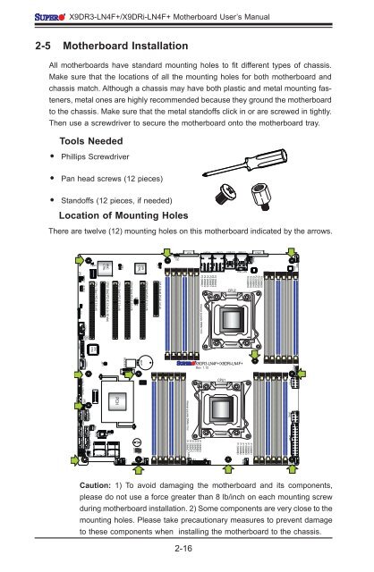
Location of Mounting Holes<br />
There are twelve (12) mounting holes on this motherboard indicated by the arrows.<br />
LE2<br />
SW1<br />
UID<br />
VGA<br />
LAN2/4<br />
LAN1/3 USB 2/3 USB 0/1<br />
FAN6<br />
COM1<br />
JPG1<br />
J21<br />
JBMC1<br />
JSTBY1<br />
COM2<br />
LEM1<br />
CPU1 Slot1 PCI-E 3.0 x16<br />
BMC<br />
CTRL<br />
CPU1 Slot2 PCI-E 3.0 x4 (in X8 slot)<br />
CPU1 Slot3 PCI-E 3.0 x16<br />
JPB1<br />
CPU2 Slot4 PCI-E 3.0 x16<br />
JP7<br />
JP6<br />
LAN<br />
CTRL<br />
CPU2 Slot5 PCI-E 3.0 x16<br />
JPL1<br />
CPU2 Slot6 PCI-E 3.0 x8<br />
P2 DIMMF3<br />
P2 DIMMF2<br />
P2 DIMMF1<br />
P2 DIMME3<br />
P2 DIMME2<br />
P2 DIMME1<br />
Alaways populate DIMMx1 first<br />
CPU2<br />
IPMI_LAN<br />
P2 DIMMG1<br />
P2 DIMMG2<br />
P2 DIMMG3<br />
P2 DIMMH1<br />
P2 DIMMH2<br />
P2 DIMMH3<br />
FAN5<br />
PHY<br />
JI2C2<br />
JI2C1<br />
SAS<br />
CTRL<br />
JTPM1<br />
JL1<br />
USB9<br />
JBT1<br />
BIOS BOX<br />
XDP-CPU<br />
JBAT1<br />
<strong>X9DR3</strong>-<strong>LN4F+</strong>/X9DRi-<strong>LN4F+</strong><br />
Rev. 1.10<br />
JPI2C1<br />
PCH<br />
XDP-PCH<br />
I-SATA5<br />
JWD1<br />
USB6/7 USB4/5<br />
I-SATA4<br />
IPMB JPME2<br />
J17<br />
JPME1 I-SATA2<br />
I-SATA1<br />
I-SATA0<br />
J18<br />
I-SATA3<br />
JSD1<br />
JRK1<br />
BIOS<br />
SAS4~7<br />
JWP1<br />
SAS0~3<br />
FANB<br />
FANA<br />
JOH1<br />
JD1<br />
SP1<br />
JF2<br />
FAN4<br />
Alaways populate DIMMx1 first<br />
P1 DIMMD3<br />
P1 DIMMD2<br />
P1 DIMMD1<br />
P1 DIMMC3<br />
P1 DIMMC2<br />
P1 DIMMC1<br />
FAN3<br />
JF1<br />
LE1<br />
CPU1<br />
P1 DIMMA1<br />
P1 DIMMA2<br />
P1 DIMMA3<br />
P1 DIMMB1<br />
P1 DIMMB2<br />
P1 DIMMB3<br />
FAN2<br />
JPW3 JPW2 JPW1<br />
FAN1<br />
Caution: 1) To avoid damaging the motherboard and its components,<br />
please do not use a force greater than 8 lb/inch on each mounting screw<br />
during motherboard installation. 2) Some components are very close to the<br />
mounting holes. Please take precautionary measures to prevent damage<br />
to these components when installing the motherboard to the chassis.<br />
2-16