X9DR3_i-LN4F+ 1.1.indb - Supermicro
X9DR3_i-LN4F+ 1.1.indb - Supermicro
X9DR3_i-LN4F+ 1.1.indb - Supermicro

You also want an ePaper? Increase the reach of your titles
YUMPU automatically turns print PDFs into web optimized ePapers that Google loves.
J21<br />
JL1<br />
J17<br />
JI2C2<br />
JI2C1<br />
J18<br />
LEM1<br />
SAS4~7<br />
JWP1<br />
SAS0~3<br />
1<br />
XDP-CPU<br />
JD1<br />
JP7<br />
JP6<br />
JF2<br />
1<br />
LE2<br />
SW1<br />
UID<br />
VGA<br />
JF1<br />
LAN2/4<br />
LE1<br />
LAN1/3 USB 2/3 USB 0/1<br />
IPMI_LAN<br />
COM1<br />
FAN1<br />
Chapter 2: Installation<br />
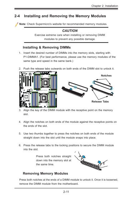
2-4 Installing and Removing the Memory Modules<br />
Note: Check <strong>Supermicro</strong>'s website for recommended memory modules.<br />
CAUTION<br />
Exercise extreme care when installing or removing DIMM<br />
modules to prevent any possible damage.<br />
Installing & Removing DIMMs<br />
1. Insert the desired number of DIMMs into the memory slots, starting with<br />
P1-DIMMA1. (For best performance, please use the memory modules of the<br />
same type and speed in the same bank.)<br />
2. Push the release tabs outwards on both ends of the DIMM slot to unlock it.<br />
JBMC1 JSTBY1<br />
JPG1<br />
COM2<br />
CPU1 Slot1 PCI-E 3.0 x16<br />
BMC<br />
CTRL<br />
CPU1 Slot2 PCI-E 3.0 x4 (in X8 slot)<br />
CPU1 Slot3 PCI-E 3.0 x16<br />
JPB1<br />
CPU2 Slot4 PCI-E 3.0 x16<br />
LAN<br />
CTRL<br />
CPU2 Slot5 PCI-E 3.0 x16<br />
JPL1<br />
CPU2 Slot6 PCI-E 3.0 x8<br />
P2 DIMMF3<br />
P2 DIMMF2<br />
P2 DIMMF1<br />
P2 DIMME3<br />
P2 DIMME2<br />
P2 DIMME1<br />
Alaways populate DIMMx1 first<br />
CPU2<br />
FAN6<br />
P2 DIMMG1<br />
P2 DIMMG2<br />
P2 DIMMG3<br />
P2 DIMMH1<br />
P2 DIMMH2<br />
P2 DIMMH3<br />
FAN5<br />
PHY<br />
Notches<br />
SAS<br />
CTRL<br />
JTPM1<br />
USB9<br />
JBT1<br />
BIOS BOX<br />
JBAT1<br />
<strong>X9DR3</strong>-<strong>LN4F+</strong>/X9DRi-<strong>LN4F+</strong><br />
Rev. 1.10<br />
JPI2C1<br />
IPMB<br />
JPME2<br />
USB6/7<br />
USB4/5<br />
JWD1<br />
I-SATA5<br />
I-SATA4 JPME1<br />
I-SATA2<br />
I-SATA0<br />
I-SATA3<br />
I-SATA1<br />
JSD1<br />
XDP-PCH<br />
JRK1<br />
BIOS<br />
PCH<br />
FANB<br />
FANA<br />
JOH1<br />
SP1<br />
FAN4<br />
Alaways populate DIMMx1 first<br />
P1 DIMMC1<br />
FAN3<br />
P1 DIMMC3<br />
P1 DIMMC2<br />
P1 DIMMD3<br />
P1 DIMMD2<br />
P1 DIMMD1<br />
CPU1<br />
P1 DIMMA1<br />
P1 DIMMA2<br />
P1 DIMMA3<br />
P1 DIMMB1 FAN2<br />
P1 DIMMB2<br />
P1 DIMMB3<br />
JPW3 JPW2 JPW1<br />
Release Tabs<br />
3. Align the key of the DIMM module with the receptive point on the memory<br />
slot.<br />
4. Align the notches on both ends of the module against the receptive points on<br />
the ends of the slot.<br />
5. Use two thumbs together to press the notches on both ends of the module<br />
straight down into the slot until the module snaps into place.<br />
6. Press the release tabs to the locking positions to secure the DIMM module<br />
into the slot.<br />
Press both notches straight<br />
down into the memory slot at<br />
the same time.<br />
Removing Memory Modules<br />
Press both notches at the ends of a DIMM module to unlock it. Once it is loosened,<br />
remove the DIMM module from the motherboard.<br />
2-11