Hunter 356 âISLAND ESCAPEâ Owner's Notes - San Juan Sailing
Hunter 356 âISLAND ESCAPEâ Owner's Notes - San Juan Sailing
Hunter 356 âISLAND ESCAPEâ Owner's Notes - San Juan Sailing

You also want an ePaper? Increase the reach of your titles
YUMPU automatically turns print PDFs into web optimized ePapers that Google loves.
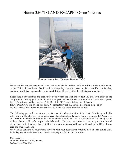
<strong>Hunter</strong> <strong>356</strong> “ISLAND ESCAPE” <strong>Owner's</strong> <strong>Notes</strong><br />
Welcome Aboard from Giles and Shannon Little!<br />
We would like to welcome you and your family and friends to share our <strong>Hunter</strong> <strong>356</strong> sailboat on the waters<br />
of the US Pacific Northwest! We have done everything we can to make this boat beautiful, comfortable,<br />
and easy to sail. We hope you have a wonderful time. Please treat her like she is your own boat.<br />
Please take a few minutes and scan these notes which are intended to help you deal with some of the<br />
equipment and sailing gear on board. That way, you can easily answer a few of those “How do I operate<br />
the ----“questions, and help us keep “ISLAND ESCAPE” in great shape for all to enjoy.<br />
ISLAND ESCAPE is a smoke free boat. We respectfully ask that you do not smoke inside or on<br />
the boat. Please only light up when ashore! We thank you for your consideration.<br />
The following pages document some of the essential characteristics of the boat. Familiarity with this<br />
information will make your sailing experience aboard significantly easier and more enjoyable! Please sign<br />
our guest book and tell us a bit about your adventure aboard. Also let us know how we can clarify or add<br />
to these “Owner’s <strong>Notes</strong>” to improve the information. Please feel free to write in the margins or at the end<br />
of the notes so that we can change it. If you add your name and address I will send you a $10 starbucks<br />
card as a small thank you!<br />
We will also consider all suggestions included with your post-charter report to the <strong>San</strong> <strong>Juan</strong> <strong>Sailing</strong> staff,<br />
including needed maintenance and repairs as safety and fun are our priorities!<br />
Bon voyage.<br />
Giles and Shannon Little, Owners<br />
Revised/Updated Mar 2013
Subject<br />
Table of Contents.<br />
Page<br />
SAFETY ABOARD 4<br />
Our 5 favorite things about Island Escape 4<br />
Most prominent quirks 5<br />
Anchors and Anchoring 5<br />
Anchor windlass<br />
6<br />
Barbecue<br />
Battery system/Charging 7<br />
Berths 7<br />
Bilge Pumps 7<br />
Boarding Ladder 8<br />
Boat Specifications 8<br />
CD player 8<br />
Dinghy 8<br />
Dodger/Bimini 9<br />
Electrical power - Electrical Panel 9<br />
- The Battery (12 Volt) 9<br />
- Circuit Breakers/Switches 9<br />
- Emergency Starting 10<br />
- AC (120Volt) Shore Power 10<br />
- AC (120V) Temporary Power 10<br />
- DC (12V) Battery Power 10<br />
- Anchor Windlass 11<br />
- Chargers & Cellular phones 11<br />
- House Lights 11<br />
Electronics - Auto-pilot 11<br />
- Color Chart Plotter & Radar 12<br />
- Depth Sounder 12<br />
- Knot Meter 13<br />
- VHF Radio 13<br />
- Wind Indicator 13<br />
Emergency/Safety 13<br />
Engine 14<br />
- Starting 14<br />
- Shifting gears 15<br />
- Engine Operation 15<br />
- Overheating 15<br />
- Shut-down 16<br />
Fuel Tank 16<br />
Hatch Board storage 16<br />
Head & Holding Tank - Flushing 16<br />
- Emptying the holding tank 17<br />
Heater/Diesel 17<br />
Inverter 18<br />
Micro-wave 18<br />
‐ 2 ‐
Outboard motor -Starting and Operation 18<br />
Refrigerator & Freezer 18<br />
Sails and Rigging Sails and Handling characteristics 19<br />
Main sail - Deploy, Furl, reef. 19<br />
Jib - Deploy, furl 20<br />
Shower 20<br />
Spare Parts and Tools. 21<br />
Stove - propane - Stove operation 21<br />
- Appliances 21<br />
Trash, Dustpan,<br />
21<br />
Handbroom, Vacuum<br />
TV and DVD player 22<br />
Water - Hot and Cold - Fresh Water 22<br />
- Tankage 22<br />
- Fresh Water Tank 23<br />
- Holding Tank 23<br />
GUEST NOTES & COMMENTS 23<br />
‐ 3 ‐
SAFETY ABOARD<br />
Safety is the primary concern of all, Captain and Crew alike. PLEASE take time to review all safety<br />
features of “ISLAND ESCAPE” before you set off on your cruise. This includes location of the Life Sling<br />
and related equipment, use of the GPS to set a “Man Overboard” waypoint, location of fire extinguishers,<br />
safety harness, etc.<br />
The Captain /Skipper is responsible for his/her crew knowing the safety features and following<br />
instructions in an emergency. LIFE JACKETS are stored in the Wet Locker located in the Shower/Head<br />
compartment. All crew should try on and properly fit a jacket prior to departing from any anchorage or<br />
dock and should know at all times where “their” jacket is located.<br />
Use of the radar/chart plotter (GPS), VHF radio, depth sounder, and other instrumentation as well as<br />
official government charts should be considered as assists to promote safety and safe navigation BUT not<br />
as a substitute for continuous alertness and caution.<br />
FIVE FAVORITE THINGS ABOUT “ISLAND ESCAPE”<br />
1. In-Mast Mainsail. Wow, what a great feature to have for cruising the inland waterways! Breezes come<br />
and go. Reducing sails or furling at the end of a long tack back to the docks can be handled from the<br />
cockpit and that’s it! No sail ties, no folding, just getting on with the fun. Remember though, that it is the<br />
outhaul and not the halyard that you need to release when furling! (speaking from experience). You never<br />
need to touch the halyard.<br />
2. Power Windlass. Pulling chain and anchors is NO FUN. Stow the chain and lash the anchor in the bow<br />
bracket and then relax. It’s done! Launching the anchor is also a snap – Just count the markings and set<br />
the anchor at the proper depth.<br />
3. Storage. There are lots of storage areas inside and out. Keep it neatly organized and you can find<br />
anything quickly. Check the inventory for items kept on board. There are storage areas under almost every<br />
cushion and mattress in the boat!<br />
4. New C90 map plotter in 2013 – easy to operate and with an easy to see screen. The furuno map<br />
plotter/radar was left in place, so one screen can be zoomed in, and the other zoomed out, or you can have<br />
one radar and one map plotter without having to split the screen!<br />
5. Extended Battery Capacity and Combiner/Start-Battery Isolator. The house battery bank was doubled<br />
in 2013 to extend the battery life while away from shore power. The Start Battery is isolated and kept at<br />
full charge. The four deep cycle battery house system<br />
provides an ample service at 400 amp hours. Battery charging is automatic, and no battery<br />
switching is required.<br />
‐ 4 ‐
MOST PROMINENT QUIRKS IN OPERATING “ISLAND ESCAPE”<br />
1. In-Mast Mainsail Furling line. The Blue control line for the in-mast mainsail furling has a thickening at<br />
the splice causing it to sometimes ‘jam’ at the cleat on the cabin-top. It often takes an small extra tug to<br />
pull the splice through the cleat. It may do the same at the winch mounted on the mast. A small lever on<br />
the topside of the winch will release the line and let it pull or slack without engaging the winch. I leave<br />
the lever or the mast loose and have never had a problem. Revised 03/2013<br />
2. Power Windlass: Use of the power windlass is great – but jamming the anchor chain is a royal pain and<br />
can be a hazard under stress or in an emergency. The chain MUST be kept clear of the<br />
leading edge of the windlass and not allowed to pile up and block the anchor feed or kink as the<br />
chain peels off the gypsy cogs. If releasing the clutch (port side of windlass) does not solve a<br />
jam, it may be necessary to unbolt the top cover to clear the gears and release the jam. By then, the circuit<br />
breaker will have blown, and will need to cool and be reset. Observing caution is the best bet!<br />
3. Checking the Oil. Yes, there really IS an oil dip-stick! It is located almost at the floorboard level on the<br />
starboard side below a bunch of hoses. A black mark has been drawn on the fiberglass outside the engine<br />
cover to indicate where (fore & aft) the elusive dip-stick is located. A small flag should be attached to the<br />
dipstick to make it easier to find. If the flagging should be missing, please add something clever or brightcolored<br />
to help the next sailor. A small mirror has been placed there to assist, and as a last resort the step<br />
cover can be removed to give you the needed room to get it in place.<br />
4. Lighting the Stove. While the stove should light automatically - once the tank is opened, the<br />
Solenoid is opened and the breaker is opened - it often doesn’t respond. Just think Propane BBQ<br />
Starter, open the appropriate burner valve on the stove, and forget about ‘automatic’. Just pretend<br />
you are really having a BBQ each and every time you use the stove-top.<br />
5. The cabin hatches have 2 settings, vent and closed. If you latch it in the middle setting they will leak if<br />
raining. You need to have the lever BELOW both black pieces to be water tight. This may not make<br />
sense if you are reading this while not on the boat, however, please remember where to find this<br />
information if you see a leak!<br />
THINGS YOU SHOULD KNOW ABOUT ‘ISLAND ESCAPE’<br />
ANCHORS AND ANCHORING<br />
ISLAND ESCAPE is equipped with two anchors, one forward in the anchor locker and one in the port<br />
swim locker. The primary bow anchor is a plow-type with 200 feet of chain and 220 feet of rope. The line<br />
is marked in red at 50-foot intervals. The secondary/stern anchor is a Danforth with 60 feet of chain and<br />
200 feet of nylon line. Island Escape draws 6”5” therefore it is advisable to allow a minimum of 10’<br />
clearance.<br />
The stern tie line is a coil of 200 feet of yellow line in the aft port swim step locker for stern tying in case<br />
of close anchoring.<br />
‐ 5 ‐
The anchor scope used in the <strong>San</strong> <strong>Juan</strong> and Gulf Islands is generally 2-4 to one. As most anchorages are<br />
15’ to 40’, expect to let out about 60’ to 100’ of chain/anchor line. Have the helmsman shift to reverse<br />
idle for at least 30 seconds to set the anchor. Half-speed reverse for about one minute will assure the<br />
anchor is secure and reduce the possibility of dragging the anchor under adverse winds or current.<br />
Anchor Windlass<br />
The electric anchor windlass first REQUIRES power from a switch on the navigation station control<br />
panel. An additional hinge-type circuit breaker for the windlass circuit is located under the chart table.<br />
Last, the up-down foot controllers for the windlass are on the forward starboard deck just aft of the anchor<br />
locker.<br />
If the anchor chain jams and/or the windless is used to pull the boat up to the anchor (instead of using the<br />
engine in low-forward gear) it is likely that the Circuit Breaker will open and power to the deck switches<br />
will be lost.<br />
Start the engine prior to operating the Windlass to avoid tripping the breaker and potentially drawing<br />
down the starting battery.<br />
Release the anchor by untying the small line retaining the chain, and pushing down with your foot the<br />
switch with the arrow pointing forward. Watch the chain and anchor line markers to determine the amount<br />
of scope released. Release the anchor sufficiently upwind so that the actual position of the boat (and<br />
swing circle) is clear of other anchored boats, rocks, or other obstructions. Check the low tide depth<br />
anticipated during your time at anchor and assure sufficient depth is available over the duration. CHECK<br />
the tide tables and correction for the locale from the sources stowed in the book rack behind the chart<br />
table. Remember, the depth sounder is set at the water-line, and the boat draws 6.5 feet.<br />
Retrieving the anchor requires good planning and crew coordination. When retrieving the anchor, never<br />
use the windlass to pull the boat up to where the anchor is set. Instead, head the boat under power toward<br />
the anchor while using the windlass to take up the stack chain. Using the “up” button with the arrow<br />
pointing back, retrieve the chain and anchor line slowly, and finally secure the anchor. Once the anchor is<br />
out of the water, retrieve it by hand, placing the anchor’s shaft on the rollers, and then lifting it into place.<br />
Stow the remaining chain with slow, short activation of the windlass, leaving a small amount of slack in<br />
the chain. Throughout the retrieval process, KEEP THE CHAIN CLEAR OF THE FORWARD SIDE OF<br />
THE WINDLASS TO AVOID JAMMING the gypsy and potentially throwing the circuit breaker.<br />
IF power is lost, clear the chain (using the clutch on the right side of the gypsy, or if that fails to release<br />
the jam, carefully remove the cover plate by removing the two screws) and check the circuit breaker and<br />
reset as necessary by closing the small black lever on the breaker by raising it to a horizontal position.<br />
Have the helmsman maintain position over the anchor set position by using idle-neutral with head to<br />
wind.<br />
KEEP the engine running throughout the retrieval process in order to avoid accidental tripping of the<br />
circuit breaker as the windlass requires significant power. Engine power will also be needed to maintain<br />
position and reduce strain on the windlass motor and gearing.<br />
Secure the anchor with the tie thru the anchor chain and close the foot switches. Turn off the breaker<br />
switch on the main electrical panel.<br />
Revised/Updated 03/2013<br />
BARBECUE<br />
The stainless steel propane BBQ is mounted on the starboard side on the stern rail. It operates on propane<br />
by use of the ‘pigtail’ hose connected to a separate tank in the propane locker. The tank valve must first<br />
be opened... Upon completion of use, the tank valve should be closed. When active use is finished, make<br />
‐ 6 ‐
sure the regulator knob is OFF. As a courtesy to the next guest, please use the wire brush attached by wire<br />
to the barbecue to clean the grill. Also, replace the cover to keep the BBQ out of the elements.<br />
IF the “automatic” spark igniter fails to operate properly, the BBQ may be started by simply using the<br />
‘propane match’ lighter provided by SJS.<br />
Revised/Updated 03/2013<br />
BATTERY SYSTEM/CHARGING<br />
ISLAND ESCAPE is equipped with a four deep cycle battery system. The master battery switch is located<br />
on the bulkhead beneath the chart table. You may simply leave the switch in the ON position The isolator<br />
assures all batteries are charged, while protecting the engine start battery from draw-down by house<br />
usage. The two battery banks are located in the cockpit locker compartment under protective covers. The<br />
4 deep cycle batteries are connected in series to provide 400 ampere-hours for house 12 volt power<br />
requirements. The Isolator detects remaining charge and will automatically keep the start battery bank at<br />
full charge and reserved for engine starting. . In an emergency the battery switch can be set to “Combine”<br />
to temporarily boost starting power. Also See “Electrical Power/Panel” section of these notes.<br />
BERTHS<br />
Island Escape is ideal for four adults. She can sleep seven . Two can sleep in the forward cabin with 6’<br />
headroom and a birth 75” long, narrowing from 82” to 12” at the bow. The aft cabin has 6’4” headroom<br />
and a queen size inner-spring mattress sleeps two. The main salon table when made into a birth is 36”<br />
forward, 52” aft and 80” long. (This requires lowering the salon table and using the settee cushion insert.)<br />
The port settee measures 22” forward, 30” aft and 79” long.<br />
Lowering the Salon Table The salon table can be lowered to make into an additional bunk:<br />
Remove all the table seat cushions<br />
Pull the pins on both sides of the table mount<br />
Lower the table until it rests on the wooden supports<br />
Replace the seat cushions<br />
The filler cushion is stored in the forward V Berth when not in use.<br />
BILGE PUMPS.<br />
There are two bilge pumps. The electric bilge pump is controlled at the electrical panel. However, the<br />
pump also has an automatic float switch wired directly to the battery bank. When there is enough bilge<br />
water to “float” the switch, the pump engages even if it is turned off at the electrical panel. Turn on the<br />
sump pump manually when showering. The sump pump empties water from the shower and refrigerator<br />
without letting the water enter the bilge (the white box under the stairs is the sump pump and hoses).<br />
Beware: If you shower without the sump pump on, water will spill into the bilge and can lead to an<br />
unpleasant odor until the bilge is cleaned and pumped.<br />
An emergency portable bilge pump is located in the cockpit storage locker. There is also a manual bilge<br />
pump handle in this locker that can be connected to fitting in the cockpit on the port side next to the<br />
engine kill switch should you lose power and/or need to rapidly remove water from the boat. Hopefully<br />
you will never hear the shower sump pump start automatically. If you do, please investigate immediately<br />
and report it to <strong>San</strong> <strong>Juan</strong> <strong>Sailing</strong> either by phone or VHF (channel 80) if there is a significant problem, or<br />
upon your return if a minor problem.<br />
‐ 7 ‐
BOARDING LADDER<br />
A small white boarding step is provided at the <strong>San</strong> <strong>Juan</strong> <strong>Sailing</strong> dock for Island Escape. This step folds<br />
and may be taken aboard for use at other ports of call. There is also a larger blue set of steps located in<br />
the port lazarette which are more secure and make it easier to get on board when at dock.<br />
BOAT SPECIFICATIONS<br />
All boat specifications such as LOA, LWL, draft, tank capacities, serial numbers, etc., can be found in the<br />
front of the guest book.<br />
CD PLAYER/STEREO<br />
The Sony CD player operates like a car stereo<br />
Simply experiment with the regular buttons to gain familiarity (see instruction guide in the front of this<br />
notebook for added detail). To load a CD, the “open” button is located in the right upper corner. The Front<br />
panel will swing down for you to put the CD into the black felt slot (red light underneath it). To play the<br />
CD, close the panel and it should play automatically. To change tracks, press the ‘seek’ button on the<br />
right of the panel. To take the CD out, reopen the panel and press the red eject button to the left. Close the<br />
panel. The stereo will beep three times when the unit is turned off on the main control panel. This is<br />
normal.<br />
Use the “FADE” function to activate the speakers in the cockpit, to have both inside and outside speakers<br />
operating, or to return audio to the cabin only. This unit also has a jack for aux. players such as ipod/mp3<br />
players.<br />
DINGHY<br />
ISLAND ESCAPE has a hard bottom inflatable 10’2” Avon RIB dinghy. For tie-up after anchoring or for<br />
towing, you should tie on the starboard side to avoid the furnace outlet vent. Towing works best when the<br />
dinghy is brought close to the boat—about 4 or 5 feet off the stern. This lifts the bow, reduces drag, and<br />
lessens the chance of wrapping the painter around the propeller. Tie the painter off twice—once at a<br />
portside cleat then tie the bitter end to the stern rail. Keep track of the oars as well. The oars should be<br />
stored flat inside the dinghy when under tow.<br />
Island Escape has a Honda 2-HP 4-stroke outboard motor. See the section in these notes for “Outboard<br />
Motor” for additional information and operating instructions. The outboard motor holds about 1/3 rd gallon<br />
of regular gas (no oil mixing is needed!) Do not store spare gasoline on the boat except inside the<br />
outboard engine. An extra gas container is secured inside the dinghy. The inflating pump is stored in the<br />
small bow locker of the dinghy, together with a pump-out hose and limited repair kit. (See section<br />
“Outboard for motor operating instructions.)<br />
PLEASE check regularly that the dinghy drain plugs on the transom are SECURLY in place prior to<br />
towing or heading out to the crab-pot or for ice cream ashore!<br />
Please use special care when beaching the dinghy (refer to the dinghy beaching procedure in your charter<br />
guest book). Most of the beaches in the Islands are strewn with barnacle covered, bottom slicing rocks.<br />
When approaching the shore, weight the dinghy aft by leaning or moving toward the back of the dinghy.<br />
Revised/Updated 03/2013<br />
Then offload everyone over the bow. Lift the dinghy/outboard motor using the hand lines on either side<br />
above the barnacle “line”, and deposit the dinghy gently on the beach. Also remember to secure the<br />
‐ 8 ‐
painter under a rock or to a log - especially in the case of a rising tide. Carefully lift the dinghy off the<br />
beach and launch carefully beyond the shore rocks rather than dragging it when departing the beach.<br />
DODGER/BIMINI<br />
The dodger, bimini and center joining section are new in the Spring of 2012! The dodger windows are<br />
plastic “glass” that is vulnerable to scratching from salt crystals, especially after sailing into a challenging<br />
breeze. The salt spray on the glass dries in the wind, leaving behind tiny salt deposits that obscure your<br />
vision. Please avoid directly touching the glass with a rag or sponge. It’s like rubbing the glass with sand<br />
paper! To clean, use generous amounts of fresh water from a hose, a pan from the galley, or a sopping wet<br />
sponge to “flood” the glass and dissolve the salt crystals away. Please do not toss items (winch handles,<br />
fenders, life jackets, etc) on top of the house and potentially hitting the dodger windows.<br />
Dodger Adjustment for Sun//Rain<br />
The Dodger consists of three separate sections. The center section may be either removed or installed in<br />
order to accommodate the wishes of the Captain and Crew relative to both sun and rain. To remove the<br />
canvas center section, first unzip the forward edge using the zipper pulls from each outboard edge. Once<br />
the zipper is open, the canvas is removed by slowly pulling the hard aft edge from the slot, pulling either<br />
to port or starboard. Carefully roll the unit taking care to NOT crease the Plexiglas window, and store the<br />
unit securely below out of the way. This provides a nice selection of both sun and shade in the cockpit. To<br />
reinstall the center canvas for either full shade or protection from rain, slide the hard track aft edge into<br />
the slot on the Cockpit Bridge, then close the zipper from each side. Close the snaps and enjoy!<br />
A canvas companionway hatch cover is also provided to offer privacy and/or ventilation when the hatch<br />
boards are not in use. If removed, please roll and store safely to prevent bending the vinyl window. This<br />
is generally kept on the shelf in the lazarette.<br />
ELECTRICAL POWER<br />
Electrical Panel<br />
The Electrical System is the “Brains” for meeting all the electrical power requirements for ISLAND<br />
ESCAPE. There are two electrical subsystems on board. The Battery System (see Battery/Charging) is 12<br />
volts, and supports most lighting and instrumentation functions. In addition, an isolated battery is the<br />
electrical source for starting the diesel engine. The Shore Power System operates on 120 Volt AC Power,<br />
obtained by connecting the Shore Power cord to an appropriate 30 Amp shore connection, available at<br />
almost all Marinas. (Adapters are provided for 20 Amp or 50 Amp connections.) In addition to powering<br />
the Battery Charger, several components onboard require AC power. See sections following. Both power<br />
systems have circuit breakers/resets which need to be checked should either system fail to function.<br />
Revised/Updated 03/2013<br />
The Battery (12 Volt)<br />
A reset is located on the bulkhead below the chart table. The Shore Power (AC breaker) is located on<br />
the aft bulkhead inside the port cockpit locker.<br />
Circuit Breakers/Switches<br />
Breaker switches for activating component sub-systems and equipment for the two ‘systems’ are arranged<br />
separately on the master electronics panel located in the salon above the chart table. The Battery functions<br />
are located on the left (DC), with the Shore Power functions on the right (AC). Each section has a master<br />
‐ 9 ‐
system switch located at the top of the respective section Most switches at the panel board are self<br />
explanatory, but some circuits are unique.<br />
Emergency Starting<br />
In emergency starting situations only, the battery switch may be set temporarily to “COMBINE” to boost<br />
available amperage. Should the ignition fail, there is a bypass starter button located under the<br />
companionway steps (behind/under the engine cover) near the engine hour meter. If you are having<br />
difficulty starting the engine, check that the kill pull in the cockpit has been pushed back in!<br />
AC (120Volt) Shore Power<br />
ISLAND ESCAPE is equipped with a 50’ yellow shore power cord for this use. (Stored in the cockpit<br />
locker ) To connect the AC Shore Power, first make sure the AC Master Switch is turned off. Also assure<br />
the shore power source is also turned off. Connect the shore power cable to the three-pronged plug on the<br />
outside of the port stern rail. Then connect to the shore power source. Turn on the shore connection, then<br />
the AC Master switch on the Electrical Panel. Reverse this process when disconnecting the AC Shore<br />
Power.<br />
Activate the A/C main when you are connected to shore power and use the individual breakers (electrical<br />
panel switches) to power various appliances. The various switches are self-explanatory, and can be<br />
individually turned on or off as desired. An Amp meter located next to the Panel will help you monitor<br />
the power consumption from the 12-Volt system as various components are used. The AC outlets only<br />
function while the boat is connected to shore power. If the AC plugs are not “on,” check the GFCI’s in the<br />
receptacle just past the chart table. If power is lost, check the AC circuit breaker located on the aft<br />
bulkhead in the large cockpit storage locker. Reset the breakers as necessary, which should then power up<br />
the AC side of the Electrical Panel.<br />
AC (120V) Temporary Power<br />
ISLAND ESCAPE also has a portable 300 watt inverter that can be used on a short term, limited basis to<br />
provide AC (120 V) power when a shore connection is not feasible. The primary application for using the<br />
inverter is to recharge a phone, but can also be used to power up the TV/DVD player when at anchor and<br />
thus AC shore power is unavailable. Both the TV and DVD units operate on AC (120 V) power only.<br />
Hence the inverter is necessary in order to operate these units from the house battery system (12 V)<br />
whenever shore power (AC) is not available. A double 12 volt plug is provided for this purpose.<br />
Please leave the TV attached to the cabinet wall. The inverter and DVD unit are stored in the forward<br />
berth on the port side, where the inverter is plugged into the 12V system. You can also use the inverter for<br />
powering other small appliances, such as laptops, game boys, phone chargers and CPAP units that do not<br />
draw much amperage.<br />
Electric hairdryers, razors, recharging units, and things that require high amperage will not work.<br />
Revised/Updated 03/2013<br />
The Battery Charger also operates on AC (120V). TURN OFF the AC Battery Charger switch on the<br />
electrical panel before starting the Engine in order to prevent damage to the charger or batteries.<br />
DC (12V) Battery Power<br />
Please acquaint yourselves with all the DC switches and what each switch operates or controls. The Main<br />
DC switch controls all the functions on the left side of the electrical panel. The DC Circuit Breaker<br />
RESET is located on the bulkhead below the chart table.<br />
‐ 10 ‐
Anchor Windlass<br />
The switch is located on the electrical panel but there is also a circuit breaker on the bulkhead below the<br />
chart table. See anchor section for details regarding use of the windlass. IF the chain jams and/or the<br />
windlass is used to pull the boat up to the anchor (instead of using the engine in low-forward gear) it is<br />
likely that the Circuit Breaker will open and power to the deck switches will be lost.<br />
Chargers & Cellular Telephones<br />
ISLAND ESCAPE is equipped with 6 12-volt “cigarette lighter” outlets that may be used for recharging<br />
your cellular telephone. To activate the plug on the port side of the steering pedestal in the cockpit, turn<br />
on the “Charger” breaker switch on the DC side of the main electrical panel. Cellular/wireless phone<br />
reception in the Islands can be quite variable by individual carrier. Be aware that Roaming Charges can be<br />
quite expensive, especially when wireless calls are routed through Canadian cellular services. This<br />
frequently happens when in the vicinity of both Stewart Island and Sucia Island even when in US waters.<br />
The inverter in the forward berth can also be used for charging items like ipods and cell phones.<br />
House Lights<br />
The interior lights on ISLAND ESCAPE are all controlled by a single breaker on the DC Electrical Panel.<br />
BUT there are both individual light switches and group switches, depending on which set of lights are to<br />
be used. Just outside the Head, close to the LP Gas switch, there is a single White light switch that<br />
controls most (but not all) of the recessed ceiling lights as a single circuit. Separately, there are small pole<br />
switches on the ceiling light at the base of the companionway steps and those in the forward and rear<br />
berth compartments. The wall-mounted swivel lights are also controlled by small switches on the lamp<br />
base.<br />
Adjust the lighting to your needs.<br />
ELECTRONICS<br />
The depth sounder, wind instrument, and autopilot are all Raytheon products. There are laminated<br />
Raytheon-prepared quick operating reference guides in the white SJS Charter notebook (or, in the chart<br />
table) to assist in using the various instruments. . If you take them out during your charter, please return<br />
them to the notebook for the next charter guests. Detailed User Guides are included in the literature<br />
packets stored in the storage compartments below the Chart Table.<br />
The power for the navigation instruments is activated by turning on the Autopilot Switch on the DC<br />
control panel. Revised/Updated 03/2012<br />
Autopilot<br />
Island Escape is equipped with an autopilot unit that can be used to steer the boat on a pre-set course<br />
while the Skipper is preoccupied with other short-term tasks or for extended open passages where<br />
obstructions, other boats, or shallow water are NOT likely. IT IS IMPERATIVE that full attention be<br />
given to sailing conditions and the location and course of the boat at all times. The autopilot is only an aid<br />
for sailing/cruising and is not a substitute for a primary focus on conditions and safety. The unit will NOT<br />
independently steer the boat into heavy weather or strong seas. This may cause the control mechanism to<br />
disengage and/or the drive belt to slip.<br />
The Autopilot is activated by using the Autopilot breaker switch on the DC Panel. This is the same switch<br />
used to activate the other electronic instruments as well. There are TWO controls that are used in<br />
‐ 11 ‐
combination. When steering a desired course, the black clutch lever located on the starboard side of the<br />
wheel is pushed downward into a locked position. Then, the toggle buttons on the instrument head are<br />
used to engage/disengage the unit (“Standby” disengages the unit’s compass control mechanism) while<br />
pressing again will engage the unit. IN ADDITION, the clutch lever MUST also be disengaged when<br />
switching to “Standby” by bringing it up to a horizontal unlocked position. Leaving the clutch lever<br />
engaged will quickly damage the motor/drive unit due to manual steering of the boat using the wheel<br />
against the tight friction of the drive unit. The round disk in the center of the wheel can be used to tighten<br />
or loosen the steering as needed for short periods. If you are finding the boat difficult to steer(hard to<br />
move the wheel) someone may have tightened this and it may need to be loosened. 3/2013<br />
Furuno Color Chart Plotter and Radar<br />
This instrument is installed at the helm. The radar switch at the electrical panel powers up this unit and the<br />
other instruments. Then use the Power Brill button on the display unit at the helm to turn the plotter<br />
on/off. A “long press” will turn the unit off and on. A “momentary press” opens the display for<br />
adjustment of brilliance, etc. Rotate the “Enter” knob to make adjustments, and then press to enter your<br />
selection of menu options or adjustments. An abbreviated “User Guide” is located in the book rack and<br />
will answer most routine operating instructions. The instrument’s full User Manual is also in the book<br />
rack. The plotter is fairly simple to use, and is much like a standard GPS with map plotter. You won’t hurt<br />
it by experimenting with the various functions a bit to learn basic operations. Please leave all basic setup<br />
functions as pre-set so that other users can easily operate the system.<br />
Raymarine Color Chart Plotter<br />
New for 2013 a C90 was installed. A booklet on usage is available in the book rack. This is not a radar,<br />
as the furuno radar was left in place. Having 2 systems allows you to use the furuno for radar and<br />
raymarine for map plotter, or to have one zoomed out for the bigger picture and one zoomed in to see<br />
rocks and hazards! 3/2013<br />
Depth Sounder<br />
The digital depth sounder will not give accurate readings beyond 200’. It is designed for use in shallow<br />
waters. In deeper water, the sensitivity on the unit increases as the transducer tries to get some reading<br />
back. Consequently, you will receive many false readings caused by currents, changes in water<br />
temperature, fish, and seaweed. Use the depth sounder only as an aid to navigation in shallow water.<br />
However, the key to avoiding rocks is not the depth sounder—but knowing where you are at all times.<br />
Rocks are the greatest navigational and safety hazard in the islands—but they are all clearly marked on<br />
the official government charts. <strong>San</strong> <strong>Juan</strong> <strong>Sailing</strong> has also clearly marked danger areas in RED on the<br />
charts. We do not recommend using the alarm. It is likely to sound at inappropriate times such as late at<br />
night while fish are passing beneath the transducer. While underway USE BOTH the charts provided<br />
aboard AND the chart plotter. Also, remember that most driftwood (including large logs) FLOAT and<br />
MOVE and must be spotted visually in order to avoid serious damage to the driveshaft and prop.<br />
Remember, the depth sounder is set to the water line, and the boat draws 6.5 feet.<br />
Revised 03/2013<br />
‐ 12 ‐
Knot Meter<br />
If the digital knot meter shows a reading of “0.00” while underway, the impeller is most likely clogged<br />
with a piece of eelgrass. Sometimes it will float off overnight. You can also try removing it by powering<br />
in reverse for a short distance. However, the GPS input to the chart plotter also provides an alternative and<br />
quite accurate indication of speed over the ground. The knot meter indicates movement relative to the<br />
water, and is impacted by tidal current, etc. The knot meter is located under the floorboard just behind the<br />
front cabin doorway.<br />
VHF Radio<br />
You should monitor channel 16 (the hailing and distress channel) during your cruise (It’s the LAW). For<br />
non-emergency communications, after establishing contact on channel 16, switch to working channels 68,<br />
69, or 79. Scan the weather channels for the one with the best reception before sailing in the morning and<br />
prior to anchoring for the evening. Remember to use proper procedures when using the VHF and, in most<br />
cases, use the low power option to reduce on-channel congestion and interference.<br />
This is generally a light wind region but weather changes can be sudden. Listen for the “inland waters of<br />
western Washington”. You will hear “Strait of <strong>Juan</strong> de Fuca” (lies south of the <strong>San</strong> <strong>Juan</strong> Islands),<br />
“Georgia Strait” (lies north), and “Rosario Strait” (runs through the eastern part of the <strong>San</strong> <strong>Juan</strong> Islands).<br />
The remote access microphone (RAM), when plugged into the port side of the pedestal, controls all radio<br />
functions of the unit mounted above the navigation station from the steering station. This can be very<br />
convenient while entering and leaving moorings. To operate the Remote VHF, first carefully plug the unit<br />
into the pedestal connector, and then turn on the panel breaker AND the main VHF radio switch. Then<br />
activate the ON switch for the remote. If the VHF is turned on before the handheld is plugged in it<br />
will not work.<br />
In case of a distress where you can no longer stand by the radio to pass your mayday, use the red distress<br />
button on the radio. First flip up the cover, then press the button.<br />
<strong>San</strong> <strong>Juan</strong> <strong>Sailing</strong> monitors channel 80 during office hours (closed Sundays). By phone you can also reach<br />
the <strong>San</strong> <strong>Juan</strong> <strong>Sailing</strong> office at (800) 677-7245 or <strong>San</strong> <strong>Juan</strong> <strong>Sailing</strong> owner, Roger Van Dyken, at (360) 224-<br />
4300 (cell) or (360) 354-5770 (home). Emergency contact numbers are also included in the white SJS<br />
Charter notebook.<br />
Wind Indicator<br />
The wind indicator is mounted at the masthead. The instrument indicates both apparent and true wind<br />
angle and wind speed in knots. The instrument is set to report apparent wind as the default. If you change<br />
this to true wind, please return the setting to apparent wind before leaving the boat at the end of your time<br />
aboard. A small black square appears on the screen below the “True” or “Apparent” labels, designating<br />
which setting is currently active. A small placard is included (normally in the Chart Table) giving further<br />
details.<br />
EMERGENCY/SAFETY<br />
In addition to the notes on Safety at the beginning of these notes you will find the following items on<br />
board:<br />
Fire Extinguishers –3 - cockpit locker, companionway, and forward stateroom.<br />
Life Sling and gear – located on the stern railing and stern lazarette<br />
Flare Kit –port cockpit locker<br />
‐ 13 ‐
Fog Horn - (manual) and extra canisters – cockpit locker and spare in chart table<br />
Radar Reflector – Shelf in cockpit locker<br />
Emergency tiller – cockpit locker<br />
Emergency rudder post – cockpit locker<br />
Flashlights – 2 – chart table and companion way<br />
First Aid Kit – under sink in head.<br />
Spotlight –a high powered Led/Halogen handheld rechargeable Spotlight is located in the hanging locker<br />
in the aft cabin. It is AC/DC rechargeable as well as “hand crank.”<br />
Absorbent Pads (Diesel spill while fueling, etc) – forward shelf, cockpit locker<br />
ENGINE<br />
ISLAND ESCAPE is powered by a 27 HP Yanmar Diesel engine. This is a very reliable engine and is the<br />
MOST IMPORTANT MECHANICAL SYSTEM aboard. Understanding how to use the engine is<br />
absolutely essential for having an enjoyable and stress-free charter experience. Please make an extra<br />
effort to fully understand the engine system before leaving the <strong>San</strong> <strong>Juan</strong> Charter docks. Ask questions,<br />
and practice all operations and functions BEFORE departing from the docks.<br />
Starting the Engine<br />
ALWAYS check that the thru-hull valve for the engine cooling water intake is OPEN before starting the<br />
engine! THEN:<br />
Check the oil level. Island Escape consumes very little oil during cruising and rarely needs oil added.<br />
Access to the engine is by unlatching the companionway stairs and pulling them towards you. The<br />
dipstick is accessed by tilting the stairs forward and locating the dipstick (with colored flagging) on the<br />
lower starboard side of the engine. There is a wide gap on the dipstick between the full line and the fill<br />
line. IF oil is needed, do not overfill. Use the onboard spare oil to add no more than a cup at a time. Then<br />
check the level again. Overfilling can be harmful to a diesel engine. The excess oil will escape somehow,<br />
perhaps by blowing the head gasket. Also, if the dipstick seemingly indicates no oil the first time you<br />
check it, reinsert and try again - the correct level will show when the air lock bubble is broken. Expect the<br />
oil to be blacker than that of a gasoline powered automobile engine. This is normal for a diesel after only<br />
a few hours of operation. While the cover is removed, check the coolant levels.<br />
Check for belt tightness and leaking fluids.<br />
Secure the companionway engine cover.<br />
Check the clear raw water strainer to make sure there is no eel grass stuck in it (under the floorboard hatch<br />
at the base of the companionway stairs where the thru hull fittings are located).<br />
Look over the stern for things that could foul the propeller.<br />
Make sure the gearshift (black handle at the pedestal) is in neutral (straight up)<br />
Push the black clutch pin on the handle in, and then push the throttle lever about 1/3 forward. This<br />
increases the rpm while leaving it in neutral. Do NOT put the transmission into forward gear!<br />
Insert the key and turn it clockwise. There is not a glow-plug on this engine. The warning buzzer will<br />
sound because there is no oil pressure.<br />
Press and hold the starter button. Expect the engine to start in 5 seconds or less. If the engine doesn’t start<br />
after 10 seconds of cranking, turn the key to the left and remove it. Wait 15 seconds and try again. An<br />
emergency start button is located in the engine compartment UNDER THE STEPS if the regular<br />
starter fails.<br />
Revised/Updated 3/2013<br />
After the engine starts, release the start button, check for water gurgling out the exhaust, then gradually<br />
ease the throttle back to a slow idle.<br />
‐ 14 ‐
Please allow 5 minutes of warm up before placing a load on the engine. Except in an emergency!. It is<br />
very hard on a diesel to be placed under load when cold.<br />
Shifting Transmission Gears<br />
When you bring the throttle back to the straight up position, the clutch pin will pop out. Now you may<br />
engage forward gear by pushing ahead on the throttle or reverse gear by pulling back on the throttle.<br />
Please remember to pause in the straight up (neutral) position when shifting from forward to reverse and<br />
vice versa. This engine tends to shudder if shifting goes rapidly from forward to reverse. Shift slowly,<br />
going thru neutral for a few seconds. New transmissions are expensive!<br />
Engine Operation<br />
The 27 HP Yanmar 3 GM series engines are very reliable. Cruising speed is approx. 6 knots at 2800<br />
RPM. Refuel when the fuel drops below ¼ full in order to avoid the possibility of sucking air or sludge<br />
into the engine when the fuel level approaches 1/8 full. Based on using 75% of the 37gallon fuel capacity<br />
yields an approximate 300-350 NM range. Please do not exceed 3000 RPM. It is hard on the diesel to<br />
push past the designed hull speed and will yield very little increase in speed. Running at higher engine<br />
RPM will significantly increase fuel consumption. At 2800 RPM, the engine uses about 0.50 to 0.79gal/hr<br />
in relatively smooth water (depending on currents and wind).<br />
Engine Overheat<br />
The engine should normally run at about 160-170 degrees (F). Check the gage frequently. If the buzzer<br />
sounds after the engine is running, immediately check the exhaust discharge on the transom. The alarm<br />
buzzer is more likely to indicate engine overheating. If water is NOT exiting the discharge port, there is a<br />
strong likelihood that the cooling water intake filter is blocked or that the water pump is malfunctioning.<br />
Turn off the engine. Check the coolant level after the engine cools down. If there is no water discharged,<br />
the seawater strainer is likely plugged with eelgrass. The best solution is to prevent this problem from<br />
occurring —keep alert for eelgrass masses, especially along those “soapy” tide and eddy lines in the<br />
water. IF eelgrass gets sucked into the engine cooling water intake, it jams the raw water strainer. IF you<br />
are motoring and see a patch of eel grass that can not be avoided, slip the engine into neutral and glide<br />
through the bed of eelgrass.<br />
To clear the strainer first raise the floorboard just forward of the companionway stairs for access. Before<br />
clearing the strainer, close the seacock below the strainer, and then remove the top of the strainer by<br />
turning it counterclockwise. Extract the stainless steel filter element. Remove the eelgrass. Open the<br />
seacock momentarily to assure that it is not clogged. Close the seacock again and carefully reinsert the<br />
stainless steel filter element into the strainer. Replace the lid and tighten by turning it clockwise until the<br />
lid is seated on the rubber gasket. Be sure to REOPEN THE SEACOCK!<br />
If the engine overheats again upon restarting, check that you remembered to reopen the seacock. If it is<br />
open, check the seal between the strainer and its lid. If the strainer is drawing air, it won’t draw water. (If<br />
needed, shut the engine down, close the seacock and open and retighten the lid on the strainer.)<br />
If water IS exiting the discharge port, the engine has most likely lost oil pressure. Check the oil pressure<br />
gauge frequently. Immediately shut down the engine, check the oil level, and if pressure is not restored<br />
contact the Maintenance Professional and/or <strong>San</strong> <strong>Juan</strong> <strong>Sailing</strong>. See emergency contact numbers in the<br />
white SJS Charter notebook.<br />
Revised/Updated 03/2013<br />
‐ 15 ‐
Engine Shutdown. Do NOT turn off or remove the ignition key while the engine is running! First<br />
bring the engine to idle and the gearshift to neutral. Allow the engine 5 minutes to cool down. Then pull<br />
the fuel cut-off handle at deck level, down by your left foot. After the engine stops, turn off the ignition<br />
and remove the key.<br />
FUEL TANK<br />
Diesel refill fitting is located starboard, stern deck, aft of the railing. A universal key to open the fitting is<br />
in the chart table. Please be very careful when fueling. The 37-gallon tank is located under the aft berth.<br />
Never allow maximum flow from the filler hose. If you do, the fill tube will surge and diesel will spill<br />
from the vents onto the side and onto the deck. It takes only a few drops of diesel fuel in the water to<br />
create sheen and subject you to a Coast Guard fine. Fill slowly and carefully. When the pipe begins to<br />
gurgle like it is full, you are probably full. You may also be able to see the diesel when looking down into<br />
the fill tube. Check the side vent and, with soap, wipe up any excess fuel to avoid yellowing the stern and<br />
polluting the water. Also be very careful of drips when removing the hose. Diesel and shoe bottoms are a<br />
very slippery and dangerous combination. After wiping, please use soapy water to scrub down any drips<br />
so it does not stain the fiberglass<br />
.<br />
HATCH BOARD STORAGE.<br />
The two piece hatch boards can be safely and securely stored in the canvas pockets mounted on the inside<br />
bulkhead of the large cockpit locker. This pocket unit is made to fit as well as to protect the Plexiglas and<br />
Teak boards. Please use this pocket accessory to keep the boards protected and out of the way.<br />
HEAD AND HOLDING TANK.<br />
Please do not put anything in the toilet that hasn’t been eaten. Deposit toilet paper (and feminine items) in<br />
the waste basket next to the toilet, not down the toilet. Zip loc bags also work well. ISLAND ESCAPE<br />
has a 30-gallon holding tank mounted in the rear swim step locker of the boat on the starboard side. <strong>San</strong><br />
<strong>Juan</strong> <strong>Sailing</strong> staff will discuss holding tanks and pump-outs at the pre-departure Skipper’s Orientation<br />
held upon your arrival<br />
Flushing<br />
A Holding Tank Full red indicator light is located on the navigation station bulkhead below the<br />
electronics panel and has been calibrated to empty and full. The Red light will light when the tank is<br />
nearly full. The separate Tank Indicator that gives levels for Fuel and Water is NOT accurate and should<br />
not be used for the holding tank. (Also see information under heading “Water – Hot and Cold Pressure<br />
System/Holding Tank” in these notes). Flushing may be done by pump-out at several stations located<br />
throughout the cruising area, although facilities are somewhat limited.<br />
Island Escape has a macerator pump and discharge thru-hull valve as explained below. This should be<br />
used only in broad, open waters where there is good water circulation and NOT activated in port or at<br />
anchorages!<br />
Tank treatment solution is located in the cabinet under the sink in the (head). There is no “Y” valve. See<br />
the basic pumping procedure printed on the pump handle unit, and the small instruction chart posted in<br />
the Head. First, move the lever to the “Wet” (Left) position and pump 2-3 full strokes to wet the bowl.<br />
Use the head, and then move the lever to the “Dry (Right) position and pump until the bowl is completely<br />
clear. Reopen the intake (“Wet”) and pump several times to fully clear the discharge line to the holding<br />
‐ 16 ‐
tank. This may take 6-7 or more full strokes. Finally move the lever to the closed (Dry) position, and<br />
pump to fully clear the bowl. IF there is any backflow, the discharge line needs to be cleared (“Dry”) to<br />
avoid both odor and spillage! A new head and lines were installed for 2013.<br />
Revised/Updated 03/2013<br />
Emptying the Holding Tank:<br />
The holding tank may be emptied by either use of shore-based pump-out stations or by use of the<br />
macerator pump and thru-hull valve. The tank may be pumped when convenient and it is preferable to<br />
empty the tank regularly instead of simply waiting until the ‘full’ indicator light appears. Avoid pumping<br />
when located in a small bay or anchorage. Pump-out may be accomplished when underway.<br />
A separate deck pump-out connection is provided for use when using shore-based pump-out stations.<br />
Follow the instructions posted at the station facilities.<br />
Procedures for use of the macerator pump-out are given below:<br />
1. The master thru-hull valve is located inside the port-side swim step locker. For safety and to avoid the<br />
need to access the swim step while the boat is underway in open waters, the holding tank discharge line is<br />
plumbed with an air loop so that once opened the valve may be left open while the vessel is in active use.<br />
The holding tank will retain all materials in the tank until the macerator pump is activated. The thru-hull<br />
valve handle should be pointing in the same direction as the hose when open: yellow handle up.<br />
When closed: the yellow handle will be pointing side-ways.<br />
2. When the discharge valve has been opened (see above) first turn on the primary macerator switch<br />
located on the 12-volt control panel.<br />
3. Push and hold the secondary macerator button just under this switch until no waste can be seen<br />
exiting the stern of the boat. This may take three to four minutes. When the effluent is frothy and bubbly,<br />
the tank is empty. Slowing the engine to forward/idle and having a crew member listen for a change in<br />
pitch of the macerator motor from inside the aft cabin is a good way to know when the tank is empty and<br />
to avoid burning out the motor. It is desirable to also rinse the tank by liberally flushing (+/- 100 ‘pumps’)<br />
water through the toilet and repeat the discharge process to reduce clogging and odors. Release the<br />
secondary macerator button to stop pump operation. Then, turn off the main macerator switch on the<br />
panel.<br />
4. THAT’S IT! There is no immediate need to close the thru-hull valve. Add new tank treatment<br />
solution through the toilet to assist in solids breakdown and to reduce odors. This is stored under the head<br />
sink (“no flex digestor”) and a small amount can be sprinkled directly into the head.<br />
If the toilet flushing pump starts to resist your flushing efforts, DO NOT continue or force the handle<br />
down. Exploding or leaking sewage is most unpleasant! Search out the problem and correct it. If you<br />
pump out the holding tank at a shore facility, please fill it with fresh water through the deck fitting to<br />
rinse, and then pump it out again. The pump-out deck fitting is located aft, just under the barbecue on the<br />
starboard side. Don’t confuse this with the Diesel Fuel fitting!<br />
If the handle is just becoming stiff due to a dry gasket add small amount vegetable oil found under<br />
bathroom sink and pump on the wet setting.<br />
HEATER/DIESEL<br />
The Webasto diesel cabin heater is located in the outboard portion of the port swim locker. Because the<br />
unit becomes very hot, a longitudinal panel separates it from the cabin wall. The heater is a forced-air<br />
‐ 17 ‐
system, so check to see if the outlets are opened or closed in the forward berth, salon, and/or aft berth as<br />
desired. Adjust to personal preferences.<br />
Revised/Updated 03/2013<br />
The heater control is located above the Chart Table, to the right of the Stereo and above the AC Electrical<br />
Panel. The “Off-Heat” switch turns the heater on and off. The Up-Down arrows are used to set the desired<br />
salon temperature. After setting the temperature, the digital dial will revert to showing the current<br />
temperature and the heater will activate as necessary to reach/hold the desired temperature. The fan will<br />
continue to run while the unit is cooling down. There are outlets at floor level in each cabin and in the<br />
main salon. The heat is dry, comfortable, and on those rainy days or cool evenings, makes a huge<br />
difference in cruising comfort! Please be patient! It may take several minutes for the heater to ignite once<br />
it is turned on and the thermostat set. You will likely hear the fan operating during the startup phase.<br />
There is ALSO an electric back-up heater located underneath the starboard side seat cushion<br />
INVERTER – See AC Temporary Power and Electrical Power<br />
MICROWAVE Use only when plugged into shore power!! There is a switch for this on the AC panel.<br />
OUTBOARD MOTOR – See separate notes related to using the dinghy. The Outboard User Manual<br />
is included in the Charter Notebook.<br />
The standard outboard engine is 4 cycle – No oil mixing is required. Use Regular Unleaded Fuel only.<br />
Start Procedure and Operation<br />
Make sure Emergency clip/lanyard is attached to engine stop switch (Red button, lower right side.)<br />
Open Fuel Cap Vent Knob – 3-4 turns – counter clockwise.<br />
Move the Fuel Value Lever to the “on” position (Lower left side at back)<br />
Set throttle lever to “start” position (Grip Handle)<br />
If Engine is “cold”, pull choke knob out. If engine is warm or has been running, chocking is not<br />
necessary. After engine starts, run for 1-2 minutes, push choke in.<br />
Pull the Recoil Starter Cord slowly until taut – then pull briskly. Engine starts.<br />
Use throttle friction knob to set throttle tension to your preference.<br />
To Reverse Engine, turn throttle to “slow” (neutral) and then turn outboard 180degrees and pivot throttle<br />
Handle<br />
Set throttle to lowest setting (slow) for neutral<br />
When stopping, simply push/hold red “stop” button. Close duel Cap Vent Know and Fuel Valve Lever in<br />
order to prevent fuel leakage. TILT engine up and lock position with small latch lever on bottom,<br />
starboard side.<br />
REFRIGERATOR & /FREEZER<br />
The well-insulated DC powered refrigerator/freezer must be turned on at the electrical panel. The<br />
thermostat is in the freezer compartment. The approximate dimensions of the refrigerator are 16”x 13”x<br />
24” deep with two shelves. The freezer works best (coldest) when things are placed close to the internal<br />
freezer element. Items placed there will remain frozen, or will freeze items such as containers for ice.<br />
Freezer dimensions are 14” x 13”x 21” deep with one shelf. We recommend running the refrigerator<br />
during the day only, turning it off and keeping the cover tight at night. This will help conserve the house<br />
‐ 18 ‐
attery power unless you are plugged in to shore power and have the battery charger turned on. Water<br />
from the refrigerator/freezer drains into the sink drain.<br />
Revised/Updated 03/2013<br />
SAILS and RIGGING.<br />
<strong>Sailing</strong> & Handling Characteristics.<br />
ISLAND ESCAPE is a delight to sail. Her sail plan features a 130% roller-furling jib and an in-mast<br />
furling main, without spinnaker. This sail plan was selected with consideration for single or short -handed<br />
sailing as well as relaxed cruising. Under power, she backs hard to port. However, once she has sternway,<br />
she is easily steered with small rudder changes.<br />
Her perfect breeze is 15-20 knots with heel at 15-20 degrees. Full sail can be carried in winds up to 18-20<br />
knots. It is easy to use the roller furling to incrementally shorten your sails. If you shorten the jib, you<br />
may want to move the jib cars forward to get a better sail shape and more control.<br />
CAUTION: Be sure to close and lock the forward hatch when preparing to raise sails as the jib sheet can<br />
be caught in it when tacking and the hatch could be damaged or pulled off.<br />
Both sails have roller furling. This makes it possible for one person to easily handle all the sails. Brief<br />
instructions are as follows:<br />
Main Sail<br />
Island Escape is equipped with the Selden “Furlin’ main sail furling and reefing system, with In-Mast<br />
Mainsail. A few minutes to acquaint yourself with this system for mainsail reefing and furling will be<br />
well worth the effort once you leave the dock and are underway.<br />
The key components of this system are:<br />
In-Mast Furling<br />
Reefing Winch (located below the Boom on the aft side of the mast<br />
Clew Outhaul<br />
“Endless” Furling Line (solid blue line) led to cockpit (Port side of Companionway)<br />
Clam-cleats for locking “Endless Line”<br />
To Deploy the Main Sail (Unfurling):<br />
Point the boat directly into the wind. (The sail can also be deployed on course, if fewer than 15 knots of<br />
wind.)<br />
Open both clam cleats on the line stoppers holding the “Endless Line” - the solid blue lines on the port<br />
housetop. It is the circular line that turns the Reefing Winch on the mast. The Reefing Winch has a control<br />
lever which can be set to “lock” (ratchet) the line or alternatively to ‘free’ which releases the winch to<br />
allow the line to move freely. This line is continuous and the splice where the line is joined is bulky and<br />
may stick or jam at the clam cleat on the cabin house. Simply pull the line through the cleat opening by<br />
hand in order to free the line while deploying the main sail.<br />
Pull the Clew Outhaul line at the Clam Cleat on the starboard housetop until the sail is all the way out and<br />
then snub it down. Using the primary winch is advised as the sail nears full set position. It is not necessary<br />
to ‘work’ the blue reef line when deploying the Main Sail. You do NOT need to winch the sail all the<br />
way out. It is much easier to manually pull the sail out and then use the winch to trim it!<br />
Adjust the sail angle with the main sheet adjustment or traveler (located on the overhead dodger support<br />
stainless bar).<br />
Revised/Updated 03/2013<br />
‐ 19 ‐
To Furl the Main Sail:<br />
Head the boat to a close reach course in order to get a nice tight wrap on the in-mast furling.<br />
Close the “Endless Loop (blue line) clam cleat closest to the companionway hatch. See point 2 above<br />
regarding the bulky splice in the blue line potentially jamming at the clam cleat.<br />
Put a wrap around the primary winch with the Clew Outhaul to keep it taut.<br />
Open the outer blue line Clam Cleat.<br />
Begin pulling the “Endless Loop” blue line at the inner Clam Cleat. This will pull the sail back into the<br />
mast.<br />
To Reef the Main Sail:<br />
The Mainsail may be reefed at any intermediate position by first setting the Reefing Winch to “FREE”<br />
and then carefully slacken off the outhaul line. Continue easing off the Clew Outhaul to roll in the desired<br />
amount of sail. The leach should be kept fairly taught. Keep slight tension on the outhaul to do this. Use<br />
the Primary Winch to take up the slack on the Endless Loop. When the desired amount of sail is rolled in,<br />
use the clew outhaul to stretch the foot of the sail. Make both ‘sides’ of the “Endless” reefing line fast to<br />
prevent slip on the Reefing Winch. If reefing from the mast, activate the lock (Ratchet”) on the Reefing<br />
Winch before reefing the sail. Use a winch handle, but NEVER leave the handle in the Winch!<br />
As noted, the mainsail Reefing Winch has a lever with two settings on it: “ratchet” and “free”. In higher<br />
wind situations this lever will need to be set to “ratchet” to help hold the mainsail in a reefed position and<br />
reduce stress on the Primary Winch. You will find a slight difference in operation between the “free”<br />
position and the “ratchet” position. In the “free” position the continuous furling line will work in both<br />
directions to furl the mainsail. In the “ratchet” position the “Endless” furling line will only furl in one<br />
direction. When leaving the boat, always lock the Reefing Winch to help reduce sail flutter.<br />
Jib Sail<br />
To Deploy the Jib Sail:<br />
Point the boat directly into the wind. In mild winds, the Jib may also be deployed (and furled) while on a<br />
normal course. The crew should adjust the jib sheet to keep the clew under control while setting the sail.<br />
Release the jib roller furling line (starboard yellow line attached to right of cockpit)<br />
Pull on the jib sheets. and sail your proper course!<br />
To Furl the Jib Sail:<br />
Point the boat directly into the wind, or in mild conditions maintain a steady course.<br />
Pull the jib roller furling line<br />
Keep gentle pressure on the jib sheet so the headsail will furl tightly<br />
Tie off the roller furling line.<br />
SHOWER<br />
Hot water is stored in the insulated 6 gallon tank located under the aft bed. It takes about 30 minutes of<br />
running the engine under load to get hot water. When on shore power, you can switch on the AC (120 V)<br />
switch on the electrical panel to heat your water electrically (also in about 30 minutes). Experienced<br />
cruisers adhere to the sailor’s shower: “get wet, turn it off, soap up, rinse off”.<br />
Be sure to turn the sump pump on at the DC electric panel. CAUTION: the engine can heat the water to<br />
scalding temperatures! On warm, sunny days, an alternative to the below deck shower is the swim<br />
platform shower. This is also a good way to rinse off salt after swimming or dirt after going ashore.<br />
‐ 20 ‐
Revised/Updated 03/2013<br />
SPARE PARTS AND TOOLS:<br />
ISLAND ESCAPE carries a modest supply of spare parts and working tools. An orange-red Spare parts<br />
box and round clear plastic container are stored with the tools in the forward compartment below the<br />
cushions of the dining settee. A few items are also stored in the primary Yellow Toolbox in the same<br />
location. An inventory listing of spares is provided in this notebook and a copy is included in the orange<br />
box. The large Yellow Toolbox is located in the forward compartment below the cushions of the dining<br />
settee. A companion black Secondary Toolbox with socket and crescent wrenches, etc (a narrow Black<br />
box) is located in this same compartment. A Multi- Tester (electronic) is stored in the Chart Table.<br />
STOVE-PROPANE<br />
The gimbaled propane stove has two burners and an oven. Two propane tanks are located in the aft<br />
cockpit starboard locker. Propane is heavier than air and requires caution. For your safety, please carefully<br />
follow these procedures:<br />
Make sure all stove control knobs are in the “off” position! THEN:<br />
Open the main valve at the propane tank all the way open and very slightly snug.<br />
Turn the LPG switch on the DC control panel ON. Next activate the electric solenoid switch located on<br />
the navigation station wall. A red light will appear, and you’ll hear a click in the propane locker as the<br />
solenoid valve opens.<br />
Ideally, no match is necessary. Push and hold in the stove control knob for a few seconds and turn to the<br />
left to high. The burner should light immediately. However, it is often difficult to light the stove<br />
automatically, so having a propane starter available is prudent and is often necessary. The oven should<br />
also light automatically by pushing knob in, turning it until it clicks – then continue pressure on the knob<br />
and turn it to the desired temperature. Hold the knob a bit longer, then release.<br />
When finished with the stove, shut off the burner(s), and then shut off the solenoid switch. (What little<br />
propane remains in the line from the tank to the galley is insignificant, and even if this tiny amount of<br />
propane were to leak into the cabin, it would not cause a problem.)<br />
If you do not intend to use the stove again in the next several hours, it is recommended that the main<br />
valve on the propane tank also be shut off. Both the solenoid valve and the hand valve protect against a<br />
potential propane leak into the main cabin. Please note that both propane valves – the hand valve and the<br />
solenoid valve – are located in the propane locker in the aft of the cockpit, which is isolated from the rest<br />
of the boat and is vented directly overboard. Any leaks within this compartment will vent down, out, and<br />
away from the boat. While the propane tanks normally last for two weeks or more, the <strong>San</strong> <strong>Juan</strong> <strong>Sailing</strong><br />
staff fills the propane tanks regularly. The gauge only measures tank pressure, NOT the actual volume of<br />
propane remaining. It is increasingly difficult to locate sources of propane in the <strong>San</strong> <strong>Juan</strong> and Canadian<br />
Gulf Islands, so confirm with the <strong>San</strong> <strong>Juan</strong> <strong>Sailing</strong> staff that the tanks are properly filled before departure.<br />
Revised/Updated 03/2013<br />
Appliances: Both a Milita and French Press are onboard. The Milita uses a #6 filter, and can be set to<br />
drain directly into a glass thermos server. The French Press is self-contained but does not include a<br />
thermos container. There are a toaster and an electric kettle for use when at dock and plugged in to AC<br />
power. These are usually located under the settee below the TV, or below the chart table. Using them<br />
both at the same time will trip the breaker on the ac panel, so they must be done one at a time.<br />
TRASH, DUSTPAN, HANDBROOM, VACUUM<br />
‐ 21 ‐
The boat has a built in dustpan located under the floorboard in the galley. This is where the small hand<br />
dustpan and broom are also stored. You may sweep directly into the built in dust pan and empty it at the<br />
end of your charter. There is a built-in Trash compartment on the Galley counter opposite the Chart Table.<br />
A standard plastic trash bag can be secured with a stretch “bungee” cord, allowing trash to be deposited<br />
directly from above. The bag can be released, tied, and stowed until convenient to deposit at an<br />
appropriate shore facility. There is a handheld AC vacuum stored under the settee by the chart table.<br />
TV/DVD PLAYER<br />
Good-Acceptable TV reception is seldom available in the Islands. There is a selection of DVD’s available<br />
onboard.<br />
The TV/DVD operates on AC (120 V) power only. Hence, it is necessary to operate this system either<br />
using an AC plug while connected to Shore Power, OR to utilize the power inverter as discussed in<br />
Section 5 of these notes. There is a small screen located inside the port side cabinet, but there is also a<br />
large flat screen that can be used that is stored below the chart table. The DVD player is located on the<br />
port shelf of the forward cabin. The remote controls for both the TV and the DVD player are in the<br />
cabinet along with the screen. This system operates much like your home system, with the exception that<br />
it must be properly connected to the power Inverter when direct AC power is not available. (NOTE: this<br />
system can also be left connected to the inverter even when AC shore power is available and the battery<br />
charger is operating).<br />
To play a DVD, first turn the switch on the AC 120 VOLT Inverter to ‘ON” position (green light). Turn<br />
the screen on with the remote control (Gray) or with the switch on top of the screen. You can mute the<br />
static with the remote. Turn the DVD player on. Press the TV/VIDEO button on the TV (Grey) remote to<br />
select “Video”. Press the “OPEN/CLOSE” button on the top of the DVD (black) remote and load the<br />
DVD disc. Close the DVD tray. DVD should then start automatically. IF not, press the “PLAY” button on<br />
the DVD. All DVD controls (menu, fwd, etc) must be controlled with the black remote and it must be<br />
aimed at the DVD player. The Volume can be controlled with the grey TV remote.<br />
To STOP the DVD, press “STOP” and “OPEN/CLOSE” and take the DVD out. Change the TV back to<br />
regular channels by pressing the “TV/VIDEO” button twice. Turn off the screen, then the DVD player,<br />
then the Inverter.<br />
WATER – HOT & COLD PRESSURE SYSTEM<br />
The Galley, Head, and Swim Step wash down systems are pressurized with both hot and cold water<br />
supplies. The 6 gallon hot water tank is relatively small, so hot water should be used sparingly. The water<br />
will heat either by running the engine or by shore power (see above relative to the shower). Heating from<br />
air temperature takes approximately 30 minutes.<br />
FRESH WATER<br />
The fresh water pump switch is located on the DC electrical panel. Please switch this off when motoring<br />
or sailing. If a tap is running and you do not hear the pump running due to the sound of motoring or<br />
sailing you could burn out the water pump and end up with no water!<br />
Revised/Updated 03/2013<br />
Tankage<br />
Island Escape has the following tank capacities:<br />
Fuel (Diesel) 38 gallons<br />
Water (Fresh) 75 gallons<br />
‐ 22 ‐
Holding Tank 30 gallons<br />
Water Heater 6 gallons<br />
Fresh Water Tank<br />
The fresh water tank fill is located inside the anchor locker at the bow. Please use the WHITE hose<br />
located in the port cockpit locker to fill the fresh water. An examination port is located under the V Berth<br />
cushions. With reasonable water conservation, you shouldn’t have a problem.<br />
Holding Tank<br />
Flushing the Head draws in sea water, so does not utilize the fresh water system, but excessive flushing<br />
does fill up the holding tank quickly! See also “Head and Holding Tank” in these notes. Remember, the<br />
guage will ALWAYS read full, and the only way to know if the tank is full is when the holding tank light<br />
comes on.<br />
GUEST NOTES AND COMMENTS<br />
PLEASE MAKE A NOTE BELOW OF ANY SUGGESTIONS, CORRECTIONS, OR NEEDED<br />
CLARIFICATIONS FOR FUTURE REVISIONS!<br />
‐ 23 ‐