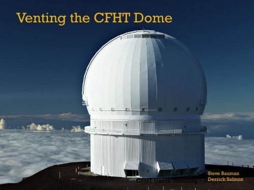
Venting the CFHT Dome
Venting the CFHT Dome
Venting the CFHT Dome

You also want an ePaper? Increase the reach of your titles
YUMPU automatically turns print PDFs into web optimized ePapers that Google loves.
Steve Bauman<br />
<strong>CFHT</strong> Users’ Meeting – May, Derrick 2013 Salmon
IQ studies, guidance and wisdom<br />
Rene Racine<br />
Water / wind tunnel models and tests<br />
Marc Baril<br />
Tom Benedict<br />
Karun Thanjavur<br />
Shiang Yu Wang – ASIAA<br />
Dan Sabin<br />
CFD calculations<br />
Konstantinos Vogiatsis<br />
Vent Project Team<br />
Contract and mechanical hardware<br />
Steve Bauman (Project Manager)<br />
DeeDee Warren<br />
<strong>CFHT</strong> daycrew<br />
Software and controls<br />
Tom Vermeulen Larry Roberts<br />
Grant Matsushige<br />
Fluid dynamics consultants<br />
Bob Breidenthal – U of Washington<br />
Bernard Tanguay – NRC-IAE Aerodynamics Lab<br />
Contractors<br />
- Caid Industries<br />
- M3<br />
- Nexus Steel<br />
- SteelTech
Optical turbulence (facility seeing) requires:<br />
- physical turbulence<br />
- incomplete mixing of air parcels of differing temperature<br />
- transport of poorly mixed air into <strong>the</strong> optical path<br />
Temperature of advected air changes much more rapidly than structural temperatures<br />
- air temperature is changed when in contact with heavy structures<br />
- stagnant air leads to large d Temp<br />
Two passive solutions:<br />
- minimize d Temp between air and telescope structures (insulate) and/or<br />
- limit <strong>the</strong> time air is in contact with structures (venting)
• image quality degrades when :<br />
• dome air temp differs from outside air<br />
• <strong>the</strong> dome slit points downwind<br />
• observing near <strong>the</strong> zenith
• Understand air flow in and around <strong>the</strong> dome – limits on improvements<br />
•Fluid dynamics consultants and literature<br />
•Water tunnel tests of 160:1 scale model<br />
•Computational fluid dynamics models<br />
• Understand <strong>the</strong> dome structure and limitations to vent design / installation<br />
•Excellent set of construction drawings from Brittain Steel (DSL)<br />
•Computer solid model of dome and telescope<br />
• Contract structural design firms to develop vents within budget, schedule and<br />
existing structure<br />
•Structural analysis of <strong>the</strong> vented dome<br />
•Detail and fabrication drawings<br />
•Fabrication<br />
•Installation
The <strong>CFHT</strong> Water Men<br />
- Tom Benedict<br />
- Marc Baril<br />
- Karun Thanjavur
• terraced terrain model<br />
• flow from <strong>the</strong> East<br />
• full dome rotation<br />
• dye probes<br />
- 6 in dome<br />
- 5 up stream<br />
- 2 down stream
• Flow from east only<br />
• All dome slit orientations: east through south to west – 15 degree increments<br />
• Vents<br />
Unvented dome<br />
8 small vents<br />
8 larger vents<br />
• Flushing / clearing times<br />
• Flow patterns<br />
- onto dome<br />
- in lee of dome<br />
- inside dome starting at floor level<br />
- inside dome in telescope tube
Vortex scours cold air and<br />
lifts it to height of building<br />
radius<br />
Air in contact with ground<br />
5 to 8 C below ambient
Winds from<br />
<strong>the</strong> East<br />
Flow angled<br />
upward ~ 20 degrees<br />
Radiatively cooled<br />
terrain<br />
Lee side upwelling<br />
Upwind stagnation point<br />
(best vent location) is low
Large fraction<br />
of flow continues<br />
in contact with<br />
dome skin<br />
Chimney flow<br />
present with or<br />
without vents<br />
Dye released here<br />
travels across cold<br />
observing floor and<br />
mixes into optical<br />
path
- Closed enclosure is a bad idea<br />
- stagnation leads to large d Temp in air<br />
- circulation into optical path<br />
- mirror seeing is likely NOT <strong>the</strong> dominant contributor to facility seeing<br />
-<strong>Venting</strong> works<br />
-- better flushing leads to lower air d Temp<br />
-- strategies needed to deal with jetting<br />
-Chimney maintained at many slit orientations – but not all<br />
-Slit front and back might reduce chimney effect (a la NTT)<br />
- Upwelling downwind should be controlled<br />
- Upwind flow tilted upward about 20 degree (Ando and Seigmund)<br />
-- stagnation point low on <strong>the</strong> vertical cross section<br />
-- keep vents low for most efficient flushing<br />
- Effective vent area < < projection onto upstream flow<br />
-- flow runs tangent to skin away from stagnation point<br />
-- Low level vortex – keep openings above height = building radius<br />
-- possibility of cold ground air mixed into <strong>the</strong> dome.
Bids solicited from 8 pre-selected vendors – November, 2011<br />
- design, build, install<br />
4 participated in on-site pre-bid review – December, 2011<br />
3 responses – February, 2012<br />
- San Jaun Construction $3.4 M US<br />
- B&C Southwest $1.9 M US<br />
- SteelTech (M3 – CAID – Nexus) $1.6 M US – selected<br />
6 month delay due to dome shutter<br />
CRC / Board approval – October, 2012<br />
OMKM / DLNR approval – December, 2012<br />
Contract signed – December, 2012<br />
Prototype installed – April, 2013<br />
Final install – September, 2013
Functional goals – vent should:<br />
- wide<br />
- low on <strong>the</strong> dome skin<br />
- maximum possible area !<br />
Real world constraints<br />
- budget<br />
- dome vertical structural webs<br />
- dome power bus bars and inner catwalk<br />
- mezzanine blockage<br />
- sever summit wea<strong>the</strong>r<br />
Final design:<br />
Vendor<br />
- 12 vents – opening 1.8 m x 5 m<br />
- concentrated toward back side<br />
- vertical roll-up wea<strong>the</strong>r door<br />
- vane (louver) on interior face<br />
- drive motors, position sensors, electrical interface box<br />
<strong>CFHT</strong><br />
- computer (PLC) control with status log<br />
- user interface for RO’s and engineering
Vertical gores – ¼ inch steel plate<br />
Vertical stiffening rib trusses<br />
Horizontal trusses on alternating gores
• 12 vent units – 6 per side – cost constrained<br />
- 15 degree intervals<br />
• mounted from <strong>the</strong> outside<br />
• no observing down time<br />
- work from 7:00 to 16:30
vents delivered as assembled units<br />
units extend from outer dome shell<br />
to inner insulation shell<br />
sealed from inter-skin cavity<br />
Outer rollup ‘garage’ door<br />
- wea<strong>the</strong>r doors<br />
- flow throttling – 4 positions<br />
- fully open<br />
- 2/3 open<br />
- 1/3 open<br />
- fully closed<br />
- inner vanes<br />
- flow redirection<br />
- flow throttling<br />
- wea<strong>the</strong>r backup<br />
- easily removable
Vent<br />
Units<br />
Junction<br />
Boxes<br />
120 V line<br />
DOME<br />
E<strong>the</strong>rnet<br />
Switch<br />
Vent power<br />
and control<br />
Breaker<br />
Panel<br />
Transformer<br />
480 V 3-phase<br />
slip ring<br />
120 V slip ring<br />
E<strong>the</strong>rnet<br />
BUILDING<br />
High Level<br />
Control
• Initially RO can select between 3 modes of operation – no “random” RO control permitted<br />
- Mode 1 fully closed – wind, rain, snow, daytime – whatever mode<br />
- Mode 2 all vents fully open, vanes pointed 20 degrees – directly into wind<br />
- Mode 3 vents fully open vanes 20 degree down into wind, BUT to reduce wind shake:<br />
a) upwind vent(s) 1/3 closed or …<br />
b) upwind vent(s) 2/3 closed or …<br />
c) upwind vent(s) fully closed<br />
• Reconfigure vents only if telescope is tracking (avoids crazies during slews)<br />
• Reconfigure vents only if dome rotated more than 10 degrees
Requirements:<br />
- cost / schedule for in-house work only (exclusive of shipping, etc)<br />
- <strong>CFHT</strong> delivers <strong>the</strong> primary mirror and mirror support systems<br />
- two options:<br />
1) refigure primary mirror maintaining conic constant and radius<br />
- maintain radius of curvature<br />
- maintain figure - parabola<br />
- 20 nm rms final figure error<br />
- test <strong>the</strong> delivered and in-process optical figure<br />
2) regrind/ refigure to a shorter focal length / new conic<br />
- radius change from 27 m to 15 m<br />
- 20 nm rms final figure error<br />
- test <strong>the</strong> delivered and in-process optical figure
The Image Quality Improvement Program SAC / BoD – 2010<br />
(a cost-effective means to improve <strong>CFHT</strong>'s delivered image quality)<br />
Four components:<br />
1) <strong>Dome</strong> <strong>Venting</strong> – in process<br />
2) Thermal Imbalance Mitigation - staffing<br />
3) <strong>Dome</strong> Painting – LoMIT - after vent installation<br />
4) Primary and Secondary Mirror Refiguring – ROM quotes
Company Refigure Regrind / refigure<br />
Exelis (Kodak, ITT)<br />
$2400k US / 77 wks No interest<br />
L3 – Brashear (Contraves) No interest > $3500k / 72 wks<br />
LZOS (Moscow)<br />
$ 325k US / 36 wks No response<br />
Sagem (Paris) $1600k US / ? > $ 2890 US / ?<br />
Uof Arizona mirror lab<br />
Interest - No<br />
specifics<br />
Interest - No<br />
specifics
MegaCam storage electronisc - SOLVED<br />
<strong>Dome</strong> hydraulic motors - ELIMINATED<br />
WIRCam (non) cooling - PENDING<br />
<strong>Dome</strong> skin print through - VENTING
![Documentation [PDF] - Canada France Hawaii Telescope ...](https://img.yumpu.com/26965302/1/190x245/documentation-pdf-canada-france-hawaii-telescope-.jpg?quality=85)