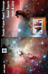
Venting the CFHT Dome
Venting the CFHT Dome
Venting the CFHT Dome

Create successful ePaper yourself
Turn your PDF publications into a flip-book with our unique Google optimized e-Paper software.
Steve Bauman<br />
<strong>CFHT</strong> Users’ Meeting – May, Derrick 2013 Salmon
IQ studies, guidance and wisdom<br />
Rene Racine<br />
Water / wind tunnel models and tests<br />
Marc Baril<br />
Tom Benedict<br />
Karun Thanjavur<br />
Shiang Yu Wang – ASIAA<br />
Dan Sabin<br />
CFD calculations<br />
Konstantinos Vogiatsis<br />
Vent Project Team<br />
Contract and mechanical hardware<br />
Steve Bauman (Project Manager)<br />
DeeDee Warren<br />
<strong>CFHT</strong> daycrew<br />
Software and controls<br />
Tom Vermeulen Larry Roberts<br />
Grant Matsushige<br />
Fluid dynamics consultants<br />
Bob Breidenthal – U of Washington<br />
Bernard Tanguay – NRC-IAE Aerodynamics Lab<br />
Contractors<br />
- Caid Industries<br />
- M3<br />
- Nexus Steel<br />
- SteelTech
Optical turbulence (facility seeing) requires:<br />
- physical turbulence<br />
- incomplete mixing of air parcels of differing temperature<br />
- transport of poorly mixed air into <strong>the</strong> optical path<br />
Temperature of advected air changes much more rapidly than structural temperatures<br />
- air temperature is changed when in contact with heavy structures<br />
- stagnant air leads to large d Temp<br />
Two passive solutions:<br />
- minimize d Temp between air and telescope structures (insulate) and/or<br />
- limit <strong>the</strong> time air is in contact with structures (venting)
• image quality degrades when :<br />
• dome air temp differs from outside air<br />
• <strong>the</strong> dome slit points downwind<br />
• observing near <strong>the</strong> zenith
• Understand air flow in and around <strong>the</strong> dome – limits on improvements<br />
•Fluid dynamics consultants and literature<br />
•Water tunnel tests of 160:1 scale model<br />
•Computational fluid dynamics models<br />
• Understand <strong>the</strong> dome structure and limitations to vent design / installation<br />
•Excellent set of construction drawings from Brittain Steel (DSL)<br />
•Computer solid model of dome and telescope<br />
• Contract structural design firms to develop vents within budget, schedule and<br />
existing structure<br />
•Structural analysis of <strong>the</strong> vented dome<br />
•Detail and fabrication drawings<br />
•Fabrication<br />
•Installation
The <strong>CFHT</strong> Water Men<br />
- Tom Benedict<br />
- Marc Baril<br />
- Karun Thanjavur
• terraced terrain model<br />
• flow from <strong>the</strong> East<br />
• full dome rotation<br />
• dye probes<br />
- 6 in dome<br />
- 5 up stream<br />
- 2 down stream
• Flow from east only<br />
• All dome slit orientations: east through south to west – 15 degree increments<br />
• Vents<br />
Unvented dome<br />
8 small vents<br />
8 larger vents<br />
• Flushing / clearing times<br />
• Flow patterns<br />
- onto dome<br />
- in lee of dome<br />
- inside dome starting at floor level<br />
- inside dome in telescope tube
Vortex scours cold air and<br />
lifts it to height of building<br />
radius<br />
Air in contact with ground<br />
5 to 8 C below ambient
Winds from<br />
<strong>the</strong> East<br />
Flow angled<br />
upward ~ 20 degrees<br />
Radiatively cooled<br />
terrain<br />
Lee side upwelling<br />
Upwind stagnation point<br />
(best vent location) is low
Large fraction<br />
of flow continues<br />
in contact with<br />
dome skin<br />
Chimney flow<br />
present with or<br />
without vents<br />
Dye released here<br />
travels across cold<br />
observing floor and<br />
mixes into optical<br />
path
- Closed enclosure is a bad idea<br />
- stagnation leads to large d Temp in air<br />
- circulation into optical path<br />
- mirror seeing is likely NOT <strong>the</strong> dominant contributor to facility seeing<br />
-<strong>Venting</strong> works<br />
-- better flushing leads to lower air d Temp<br />
-- strategies needed to deal with jetting<br />
-Chimney maintained at many slit orientations – but not all<br />
-Slit front and back might reduce chimney effect (a la NTT)<br />
- Upwelling downwind should be controlled<br />
- Upwind flow tilted upward about 20 degree (Ando and Seigmund)<br />
-- stagnation point low on <strong>the</strong> vertical cross section<br />
-- keep vents low for most efficient flushing<br />
- Effective vent area < < projection onto upstream flow<br />
-- flow runs tangent to skin away from stagnation point<br />
-- Low level vortex – keep openings above height = building radius<br />
-- possibility of cold ground air mixed into <strong>the</strong> dome.
Bids solicited from 8 pre-selected vendors – November, 2011<br />
- design, build, install<br />
4 participated in on-site pre-bid review – December, 2011<br />
3 responses – February, 2012<br />
- San Jaun Construction $3.4 M US<br />
- B&C Southwest $1.9 M US<br />
- SteelTech (M3 – CAID – Nexus) $1.6 M US – selected<br />
6 month delay due to dome shutter<br />
CRC / Board approval – October, 2012<br />
OMKM / DLNR approval – December, 2012<br />
Contract signed – December, 2012<br />
Prototype installed – April, 2013<br />
Final install – September, 2013
Functional goals – vent should:<br />
- wide<br />
- low on <strong>the</strong> dome skin<br />
- maximum possible area !<br />
Real world constraints<br />
- budget<br />
- dome vertical structural webs<br />
- dome power bus bars and inner catwalk<br />
- mezzanine blockage<br />
- sever summit wea<strong>the</strong>r<br />
Final design:<br />
Vendor<br />
- 12 vents – opening 1.8 m x 5 m<br />
- concentrated toward back side<br />
- vertical roll-up wea<strong>the</strong>r door<br />
- vane (louver) on interior face<br />
- drive motors, position sensors, electrical interface box<br />
<strong>CFHT</strong><br />
- computer (PLC) control with status log<br />
- user interface for RO’s and engineering
Vertical gores – ¼ inch steel plate<br />
Vertical stiffening rib trusses<br />
Horizontal trusses on alternating gores
• 12 vent units – 6 per side – cost constrained<br />
- 15 degree intervals<br />
• mounted from <strong>the</strong> outside<br />
• no observing down time<br />
- work from 7:00 to 16:30
vents delivered as assembled units<br />
units extend from outer dome shell<br />
to inner insulation shell<br />
sealed from inter-skin cavity<br />
Outer rollup ‘garage’ door<br />
- wea<strong>the</strong>r doors<br />
- flow throttling – 4 positions<br />
- fully open<br />
- 2/3 open<br />
- 1/3 open<br />
- fully closed<br />
- inner vanes<br />
- flow redirection<br />
- flow throttling<br />
- wea<strong>the</strong>r backup<br />
- easily removable
Vent<br />
Units<br />
Junction<br />
Boxes<br />
120 V line<br />
DOME<br />
E<strong>the</strong>rnet<br />
Switch<br />
Vent power<br />
and control<br />
Breaker<br />
Panel<br />
Transformer<br />
480 V 3-phase<br />
slip ring<br />
120 V slip ring<br />
E<strong>the</strong>rnet<br />
BUILDING<br />
High Level<br />
Control
• Initially RO can select between 3 modes of operation – no “random” RO control permitted<br />
- Mode 1 fully closed – wind, rain, snow, daytime – whatever mode<br />
- Mode 2 all vents fully open, vanes pointed 20 degrees – directly into wind<br />
- Mode 3 vents fully open vanes 20 degree down into wind, BUT to reduce wind shake:<br />
a) upwind vent(s) 1/3 closed or …<br />
b) upwind vent(s) 2/3 closed or …<br />
c) upwind vent(s) fully closed<br />
• Reconfigure vents only if telescope is tracking (avoids crazies during slews)<br />
• Reconfigure vents only if dome rotated more than 10 degrees
Requirements:<br />
- cost / schedule for in-house work only (exclusive of shipping, etc)<br />
- <strong>CFHT</strong> delivers <strong>the</strong> primary mirror and mirror support systems<br />
- two options:<br />
1) refigure primary mirror maintaining conic constant and radius<br />
- maintain radius of curvature<br />
- maintain figure - parabola<br />
- 20 nm rms final figure error<br />
- test <strong>the</strong> delivered and in-process optical figure<br />
2) regrind/ refigure to a shorter focal length / new conic<br />
- radius change from 27 m to 15 m<br />
- 20 nm rms final figure error<br />
- test <strong>the</strong> delivered and in-process optical figure
The Image Quality Improvement Program SAC / BoD – 2010<br />
(a cost-effective means to improve <strong>CFHT</strong>'s delivered image quality)<br />
Four components:<br />
1) <strong>Dome</strong> <strong>Venting</strong> – in process<br />
2) Thermal Imbalance Mitigation - staffing<br />
3) <strong>Dome</strong> Painting – LoMIT - after vent installation<br />
4) Primary and Secondary Mirror Refiguring – ROM quotes
Company Refigure Regrind / refigure<br />
Exelis (Kodak, ITT)<br />
$2400k US / 77 wks No interest<br />
L3 – Brashear (Contraves) No interest > $3500k / 72 wks<br />
LZOS (Moscow)<br />
$ 325k US / 36 wks No response<br />
Sagem (Paris) $1600k US / ? > $ 2890 US / ?<br />
Uof Arizona mirror lab<br />
Interest - No<br />
specifics<br />
Interest - No<br />
specifics
MegaCam storage electronisc - SOLVED<br />
<strong>Dome</strong> hydraulic motors - ELIMINATED<br />
WIRCam (non) cooling - PENDING<br />
<strong>Dome</strong> skin print through - VENTING
![Documentation [PDF] - Canada France Hawaii Telescope ...](https://img.yumpu.com/26965302/1/190x245/documentation-pdf-canada-france-hawaii-telescope-.jpg?quality=85)