Installation Smart-UPS VT 10-40 kVA, 400 V with ... - SWS a.s.
Installation Smart-UPS VT 10-40 kVA, 400 V with ... - SWS a.s.
Installation Smart-UPS VT 10-40 kVA, 400 V with ... - SWS a.s.

You also want an ePaper? Increase the reach of your titles
YUMPU automatically turns print PDFs into web optimized ePapers that Google loves.
<strong>Installation</strong><br />
<strong>Smart</strong>-<strong>UPS</strong> <strong>VT</strong><br />
<strong>10</strong>-<strong>40</strong> <strong>kVA</strong>, <strong>40</strong>0 V <strong>with</strong> batteries<br />
<br />
<br />
<br />
<br />
<strong>10</strong>-<strong>40</strong> <strong>kVA</strong>.<br />
20-<strong>40</strong> <strong>kVA</strong> <strong>with</strong>out front panel.<br />
<strong>10</strong>-15 <strong>kVA</strong> <strong>with</strong>out front panel.<br />
<strong>10</strong>-<strong>40</strong> <strong>kVA</strong> from the rear. (The power<br />
cable landing area is behind the upper<br />
rear cover).<br />
<br />
<br />
<br />
<strong>10</strong>-20 <strong>kVA</strong>.<br />
<strong>10</strong>-20 <strong>kVA</strong> <strong>with</strong>out front panel.<br />
<strong>10</strong>-20 <strong>kVA</strong> from the rear. (The power<br />
cable landing area is behind the upper<br />
rear cover).<br />
IMPORTANT SAFETY INSTRUCTIONS<br />
SAVE THESE INSTRUCTIONS<br />
Warning: ALL safety instructions in the Safety Sheet<br />
(990-2822) must be read, understood, and followed when<br />
installing the <strong>UPS</strong> system. Failure to do so could result in<br />
equipment damage, serious injury, or death.<br />
Warning: After the <strong>UPS</strong> has been electrically wired, do<br />
not start it up. Start-up is commissioned to APCauthorized<br />
personnel only.<br />
Note: Ensure that the unit is in its final location prior to<br />
installation.<br />
Note: Battery and utility power must not be connected until<br />
all other wiring has been completed.<br />
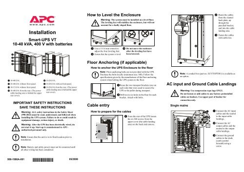
How to Level the Enclosure<br />
<br />
Warning: The system must be installed on a level floor.<br />
The leveling feet will stabilize the enclosure, but will not<br />
account for a badly sloped floor.<br />
Use a 13/14 mm wrench to <br />
adjust the four leveling feet.<br />
Ensure that the system is level.<br />
Floor Anchoring (if applicable)<br />
How to anchor the <strong>UPS</strong> Enclosure to the floor<br />
Cable entry<br />
Note: Floor-anchoring bolts are not provided <strong>with</strong> the <strong>UPS</strong>.<br />
Purchase the bolts locally (minimum size: M8). Follow the<br />
specifications given by the manufacturer of the floor anchoring<br />
system when bolting the <strong>UPS</strong> system to the floor.<br />
How to prepare for the cables<br />
<br />
<br />
<br />
<br />
<br />
Reuse the two transport brackets (one on<br />
each side) that were used to secure the<br />
<strong>UPS</strong> to the pallet during transport.<br />
Drill two to six holes in the floor for each<br />
bracket. Attach <strong>with</strong> bolts.<br />
<br />
<br />
Do not move the enclosure<br />
after the leveling feet have<br />
been lowered.<br />
From the rear of the <strong>UPS</strong> loosen<br />
the six M4 screws from the<br />
upper cover (the cable landing<br />
area) on the back and remove.<br />
Note: A conduit box (part no. SU<strong>VT</strong>OPT001) is available as<br />
an option.<br />
AC input and Ground Cable Landings<br />
Single mains<br />
Warning: Use compression type lugs ONLY.<br />
Do not loosen or add cables to any factory preinstalled<br />
cables on busbars. Use upper part of busbar for<br />
connection only.<br />
<br />
<br />
<br />
<br />
<br />
<br />
<br />
<br />
<br />
<br />
<br />
Route the cables<br />
from the slanted<br />
back plate, up<br />
through the<br />
punched bracket,<br />
and into the cable<br />
landing area.<br />
Fasten the cables<br />
<strong>with</strong> cable ties.<br />
Connect the AC input<br />
cables and the neutral<br />
to the input cable<br />
landings.<br />
Connect the AC<br />
output cables and the<br />
neutral to the output<br />
cable landings.<br />
Connect the ground<br />
cables to the studs<br />
(earth symbol<br />
beneath) using a<br />
screw.<br />
990-1986A-001 05/2008<br />
*990-1986A-
Dual Mains<br />
Communication Cables<br />
J<strong>10</strong>8<br />
3: Dry Contacts Normally Closed<br />
<br />
Remove the three<br />
busbars A, B, and<br />
C by removing two<br />
M6 screws from<br />
each busbar.<br />
J<strong>10</strong>6 and J<strong>10</strong>8 pin connections<br />
Note: The <strong>UPS</strong> must be connected to either a dry contact or a<br />
24 VDC EPO (Emergency Power Off) switch.<br />
1<br />
2<br />
3<br />
4<br />
5<br />
6<br />
EPO circuit<br />
EPO is activated when a connection from<br />
pin 3 to pin 5 is opened.<br />
Connections: 4-6.<br />
<br />
<br />
<br />
Connect the AC<br />
input cables and the<br />
neutral to the input<br />
cable landings.<br />
Connect the bypass<br />
cables and the<br />
neutral to the<br />
bypass cable<br />
landings.<br />
Note: The external EPO +24 VDC, 1500 mA circuit can be<br />
supplied through other vendors.<br />
Note: Always follow the pin connection procedures from the<br />
top and work down: J<strong>10</strong>6 (8-1), J<strong>10</strong>8 (1-6).<br />
J<strong>10</strong>8 pin connections:<br />
J<strong>10</strong>8<br />
1<br />
2<br />
3<br />
4<br />
5<br />
6<br />
EPO circuit<br />
Pin connections J<strong>10</strong>6 (<strong>UPS</strong>).<br />
4: +24 V Normally Closed<br />
EPO is activated when a SELV 24 VDC<br />
voltage is removed from pin 3 <strong>with</strong><br />
reference to pin 4.<br />
<br />
<br />
<br />
<br />
<br />
Battery Cable Landings<br />
(if applicable)<br />
<br />
<br />
Connect the output<br />
cables and the<br />
neutral to the<br />
output cable<br />
landings.<br />
Connect the ground<br />
cables to the studs<br />
(earth symbol<br />
beneath) using a<br />
screw.<br />
<br />
<br />
1 Normally open EPO<br />
2 Normally open EPO return<br />
3 Normally closed EPO<br />
4 Normally closed EPO return<br />
5 +24 V SELV supply<br />
6 SELV ground<br />
J<strong>10</strong>6 pin connections:<br />
8 Ext. charging control return<br />
7 External control of charging<br />
6 Q3 active return<br />
5 Q3 active<br />
4 Battery measurement supply*<br />
3 Battery unit quantity*<br />
2 Max. battery temperature*<br />
1 Battery measurement return*<br />
* Should be used <strong>with</strong> APC XR<br />
Enclosures<br />
EPO wiring – pin connections J<strong>10</strong>8. Connect the EPO cable, using<br />
one of the following four wiring configurations.<br />
J<strong>10</strong>6<br />
8<br />
7<br />
6<br />
5<br />
4<br />
3<br />
2<br />
1<br />
Charging control switch<br />
Q3 switch<br />
4<br />
3<br />
2<br />
1<br />
J200 (XR Batteries)<br />
Pins 1 to 4 are for battery measurement (only<br />
applicable to APC XR Battery Enclosures).<br />
Pins 5 and 6 are for external maintenance<br />
bypass Q3 (auxiliary switch N/C type).<br />
When Q3 is closed, signals are fed back to the<br />
<strong>UPS</strong> controller.<br />
Pins 7 and 8 are for external charge control.<br />
When 7 and 8 are closed, the <strong>UPS</strong> charges<br />
batteries <strong>with</strong> a pre-defined percentage (0-25-<br />
50-75-<strong>10</strong>0%) of the maximum charging power.<br />
To be used in generator applications, or if<br />
special codes require control of charging.<br />
When Q3 is closed, signals are fed back to the<br />
<strong>UPS</strong> controller.<br />
Note: When connecting the Q3 auxiliary signal, use goldplated<br />
N/C auxiliary switch.<br />
Note: Reinstall the cable landing cover.<br />
<br />
Connect battery<br />
cables BAT+, BAT÷,<br />
and the N cable to<br />
the battery cable<br />
landings.<br />
J<strong>10</strong>8<br />
1<br />
2<br />
3<br />
4<br />
5<br />
6<br />
EPO circuit<br />
1: Dry Contracts Normally Open<br />
EPO is activated when pin 1 is connected<br />
to pins 3 and 5.<br />
Connections: 2-4-6, 3-5 and<br />
1 =><br />
<br />
Note: ONLY APC <strong>Smart</strong>-<strong>UPS</strong> <strong>VT</strong> Battery Enclosure<br />
(SU<strong>VT</strong>RBXRB6) must be connected to the <strong>UPS</strong>.<br />
J<strong>10</strong>8<br />
1<br />
2<br />
3<br />
4<br />
5<br />
6<br />
EPO circuit<br />
2: +24 V Normally Open<br />
EPO is activated when an isolated SELV 24<br />
VDC voltage is supplied on pin 1 <strong>with</strong><br />
reference to pin 2.<br />
Connections: 3-5 and 4-6.<br />
2
Connection of APC communication options –<br />
PowerChute software and Temperature Sensor<br />
(identical cable routing)<br />
<br />
Note: The Temperature Sensor is provided in a plastic bag<br />
attached to the front of the <strong>UPS</strong> behind the front panel.<br />
<br />
<br />
<br />
Network<br />
Management<br />
card<br />
<br />
<br />
<br />
<br />
<br />
<br />
<br />
<br />
<br />
Turn the screw below the<br />
user interface display to<br />
the right to the unlocked<br />
position.<br />
Lift the front panel to free<br />
the two tabs at the bottom<br />
of the enclosure.<br />
Remove the two screws<br />
from the cable inlet at the<br />
front and remove cableinlet<br />
plate.<br />
Guide the cable through<br />
the hole in the bottom<br />
plate and up through the<br />
cable inlet.<br />
Guide the cable through<br />
the side panel hole and<br />
run the cable upwards<br />
inside the panel.<br />
Pull the cable out of the<br />
side panel through the<br />
hole closest to the<br />
Network Management<br />
Card area.<br />
Plug the cable into the<br />
probe socket /<br />
PowerChute inlet.<br />
Reattach the cable-inlet<br />
plate ().<br />
Specifications<br />
AC input<br />
AC output<br />
Warning: The <strong>UPS</strong> must be supplied from a 3x380/220 V /<br />
3x<strong>40</strong>0/230 V / 3x415/2<strong>40</strong> V, L1 L2 L3 N PE, 50/60 Hz<br />
source.<br />
<strong>10</strong> <strong>kVA</strong><br />
<strong>UPS</strong> ratings 380 V <strong>40</strong>0 V 415 V<br />
Input frequency (Hz) <strong>40</strong>-70 <strong>40</strong>-70 <strong>40</strong>-70<br />
Nominal input current (A) 1 13.0 12.3 11.9<br />
Max. input current (A) 2 14.3 13.5 13.1<br />
Input current limit (A) 3 16.8 16.8 16.8<br />
15 <strong>kVA</strong> 20 <strong>kVA</strong><br />
<strong>UPS</strong> ratings 380 V <strong>40</strong>0 V 415 V 380 V <strong>40</strong>0 V 415 V<br />
Input frequency (Hz) <strong>40</strong>-70 <strong>40</strong>-70 <strong>40</strong>-70 <strong>40</strong>-70 <strong>40</strong>-70 <strong>40</strong>-70<br />
Nominal input current (A) 1 19.4 18.5 17.8 26.0 24.7 23.8<br />
Max. input current (A) 2 21.4 20.3 19.6 28.6 27.2 26.2<br />
Input current limit (A) 3 25.2 25.2 25.2 33.8 33.8 33.8<br />
30 <strong>kVA</strong> <strong>40</strong> <strong>kVA</strong><br />
<strong>UPS</strong> ratings 380 V <strong>40</strong>0 V 415 V 380 V <strong>40</strong>0 V 415 V<br />
Input frequency (Hz) <strong>40</strong>-70 <strong>40</strong>-70 <strong>40</strong>-70 <strong>40</strong>-70 <strong>40</strong>-70 <strong>40</strong>-70<br />
Nominal input current (A) 1 38.6 36.7 35.3 51.7 49.1 47.3<br />
Max. input current (A) 2 42.5 <strong>40</strong>.3 38.9 56.8 54.0 52.1<br />
Input current limit (A) 3 50.1 50.1 50.1 66.9 66.9 66.9<br />
<strong>10</strong> <strong>kVA</strong><br />
<strong>UPS</strong> ratings 380 V <strong>40</strong>0 V 415 V<br />
Nominal output current (A) 15.2 14.4 13.9<br />
15 <strong>kVA</strong> 20 <strong>kVA</strong><br />
<strong>UPS</strong> ratings 380 V <strong>40</strong>0 V 415 V 380 V <strong>40</strong>0 V 415 V<br />
Bypass input<br />
<strong>10</strong> <strong>kVA</strong><br />
<strong>UPS</strong> ratings 380 V <strong>40</strong>0 V 415 V<br />
Input frequency (Hz) 50-60 50-60 50-60<br />
Nominal input current (A) 1 13.0 12.3 11.9<br />
15 <strong>kVA</strong> 20 <strong>kVA</strong><br />
<strong>UPS</strong> ratings 380 V <strong>40</strong>0 V 415 V 380 V <strong>40</strong>0 V 415 V<br />
Input frequency (Hz) 50-60 50-60 50-60 50-60 50-60 50-60<br />
Nominal input current (A) 1 19.4 18.5 17.8 26.0 24.7 23.8<br />
30 <strong>kVA</strong> <strong>40</strong> <strong>kVA</strong><br />
<strong>UPS</strong> ratings 380 V <strong>40</strong>0 V 415 V 380 V <strong>40</strong>0 V 415 V<br />
Nominal voltage (V) 50-60 50-60 50-60 50-60 50-60 50-60<br />
Nominal input current (A) 1 38.6 36.7 35.3 51.7 49.1 47.3<br />
Battery input<br />
<strong>UPS</strong> ratings 15 <strong>kVA</strong> 15 <strong>kVA</strong> 20 <strong>kVA</strong> 30 <strong>kVA</strong> <strong>40</strong> <strong>kVA</strong><br />
Nominal voltage (V) ± 192 ± 192 ± 192 ± 192 ± 192<br />
External battery fuse (A) 125 125 125 125 125<br />
125 1.6-1.75 V/cell (automatic, depending on load)<br />
Notes:<br />
1. Input current based on rated load and batteries fully charged.<br />
2. Input current based on full battery charge, nominal voltage, and rated<br />
load.<br />
3. Current limitation through electronic current limiting is based on full<br />
battery recharge and –15% input voltage.<br />
<br />
<br />
Nominal output current (A) 22.8 21.7 20.9 30.4 28.9 27.8<br />
30 <strong>kVA</strong> <strong>40</strong> <strong>kVA</strong><br />
<strong>UPS</strong> ratings 380 V <strong>40</strong>0 V 415 V 380 V <strong>40</strong>0 V 415 V<br />
Nominal output current (A) 45.6 43.3 41.7 60.8 57.7 55.6<br />
3
Recommended current protection<br />
Minimum breaker settings<br />
Checklist<br />
Note: AC input/output over-current protection and AC input/<br />
output disconnect must be provided by the customer.<br />
Q1 Q5 Q3 Q2<br />
Internal<br />
fault<br />
800%<br />
overload<br />
bypass<br />
operation<br />
150%<br />
overload<br />
normal/<br />
battery<br />
operation<br />
125%<br />
overload<br />
normal/<br />
battery<br />
operation<br />
Continuously<br />
<br />
<br />
Check that the power wiring is torqued to 7 Nm.<br />
Verify clockwise phase-rotation (L1, L2, L3) and make sure a<br />
neutral connection is present.<br />
<strong>10</strong> <strong>kVA</strong> 16 16 16 16<br />
15 <strong>kVA</strong> 25 25 25 25<br />
20 <strong>kVA</strong> 35 35 35 35<br />
30 <strong>kVA</strong> 50 50 50 50<br />
<strong>40</strong> <strong>kVA</strong> 63 63 63 63<br />
Notes 1 2<br />
Note 1: Required upstream current protection, mains input: gL type fuse<br />
Note 2: Required upstream current protection, bypass input: gL type fuse.<br />
Recommended cable sizes<br />
The recommended cable sizes are based on an environment <strong>with</strong> an<br />
ambient temperature of 30°C.<br />
Mains input<br />
[mm 2 ]<br />
AC output<br />
[mm 2 ]<br />
Battery input<br />
[mm 2 ] 70ºC<br />
Wire<br />
<strong>10</strong> <strong>kVA</strong> 2.5 2.5 6 2.5<br />
15 <strong>kVA</strong> 6 6 <strong>10</strong> 6<br />
20 <strong>kVA</strong> <strong>10</strong> <strong>10</strong> 16 <strong>10</strong><br />
30 <strong>kVA</strong> 16 16 35 16<br />
<strong>40</strong> <strong>kVA</strong> 25 25 50 25<br />
Bypass input<br />
[mm 2 ]<br />
Note: Use Molex lug type or equivalent, and crimp to<br />
manufacturer’s specifications.<br />
Warning: At <strong>10</strong>0% switch mode load, the neutral must be<br />
rated for 200% phase current.<br />
<strong>10</strong> <strong>kVA</strong><br />
Mains input 2 kA – – – 16.4 A<br />
Bypass input 1.7 kA 121.5 A – – 16.7 A<br />
Output 9 kA 121.5 A 22.8 A 19 A 16.7 A<br />
Duration