Chenbro
Chenbro
Chenbro

Create successful ePaper yourself
Turn your PDF publications into a flip-book with our unique Google optimized e-Paper software.
ES34169 Chassis User’s Manual<br />
Rev. A1<br />
<strong>Chenbro</strong><br />
ES34169<br />
Chassis User Manual<br />
April / 2 / 2010<br />
www.chenbro.com 1
ES34169 Chassis User’s Manual<br />
Rev. A1<br />
Copyright<br />
Copyright © 2007 <strong>Chenbro</strong> Micom Co., Ltd.. All rights reserved.<br />
Unless otherwise indicated, all materials in this manual are copyrighted by <strong>Chenbro</strong> Micom<br />
Co., Ltd.. All rights reserved. No part of this manual, either text or image may be used for any<br />
purpose other than internal use within purchasing company. Therefore, reproduction,<br />
modification in any form or by any means, electronic, mechanical or otherwise, for reasons<br />
other than internal use, is strictly prohibited without prior written permission.<br />
<strong>Chenbro</strong> Micom Co., Ltd. reserves the right to make improvement and modification to the<br />
products indicated in this manual at any time. Specifications are therefore subject to change<br />
without prior notice.<br />
Information provided in this manual is intended to be accurate and reliable. However,<br />
<strong>Chenbro</strong> Micom Co., Ltd., assumes no responsibility for its use, nor for any infringements upon<br />
the rights of third parties, which may result from its use.<br />
Technical Support<br />
<strong>Chenbro</strong> works hard to offer our customers maximum performance from our chassis.<br />
But in case you have any problem with our product you can find supports from the<br />
following resources.<br />
Web Support<br />
Detail information of our products is in our website. You can find technical updates, installation<br />
guides, FAQs, Technical specifications and more. Our web address is: www.chenbro.com.<br />
Email Support<br />
You can also fill out the technical support form at our Technical Support page. Your technical<br />
issue inquiries will be sent directly to our support professionals.<br />
Phone Support<br />
You can also contact <strong>Chenbro</strong> HQ or branch office for immediate support; contact<br />
Information is as following:<br />
<strong>Chenbro</strong> HQ <strong>Chenbro</strong> Europe B.V. <strong>Chenbro</strong> Micom (USA) Inc.<br />
Tel: 886-2-8226-5500 Tel: 31-40-295-2045 Tel: 1-909-947-3200<br />
Fax: 886-2-8226-5423 Fax: 31-40-295-2044 Fax : 1-909-947-4300<br />
www.chenbro.com 2
ES34169 Chassis User’s Manual<br />
Rev. A1<br />
Content<br />
Packing List................................................................................................................4<br />
ES34169 Chassis...............................................................................................4<br />
Optional Items....................................................................................................4<br />
Features.......................................................................................................................5<br />
Technical Specifications.........................................................................................5<br />
Opening the Chassis................................................................................................6<br />
Side Panel Removal..........................................................................................7<br />
Front Bezel Removal........................................................................................7<br />
Motherboard Cage Removal ..........................................................................8<br />
Devices Installation ..................................................................................................9<br />
Installing Slim Optical Drive (Slim ODD) ....................................................9<br />
Installing 3.5” SATA-II Hard Drive...............................................................10<br />
Installing Card Reader ...................................................................................10<br />
Installing Riser Card.......................................................................................12<br />
Installing 2.5” HDD..........................................................................................13<br />
Connecting Devices ...............................................................................................13<br />
Connecting SATA-II Cables ..........................................................................13<br />
Connecting Power Cables ............................................................................14<br />
Connecting Front Panel I/O, LED and Slim ODD Cables......................14<br />
a. USB 2.0 cable connection ................................................................14<br />
b. Front display cable connection......................................................15<br />
c. Slim ODD cable connection.............................................................15<br />
d. Cable management ............................................................................15<br />
Power Supply ...........................................................................................................16<br />
Specification: ...................................................................................................16<br />
Protection: ........................................................................................................16<br />
Environmental Requirements:.....................................................................16<br />
Mechanical Dimension: .................................................................................16<br />
2-port SATA-II Backplane ......................................................................................17<br />
Hardware Specification:................................................................................17<br />
Backplane Connectors ..................................................................................17<br />
www.chenbro.com 3
ES34169 Chassis User’s Manual<br />
Rev. A1<br />
Packing List<br />
ES34169 Chassis<br />
Item Q’ty Remark<br />
Chassis 1<br />
3.5” HDD tray 4<br />
2-port SAS / SATA-II backplane 2<br />
70x15 mm rear fan 2<br />
SATA-II cable, 440 mm 4<br />
120 watts internal PSU 1<br />
Screw pack for motherboard 1<br />
Screw pack for HDD 1<br />
USB 2.0 cable 1<br />
Key, front door 1<br />
Optional Items<br />
Item Part # Remark<br />
Power Cord, Europe 34H032100-011<br />
Power Cord, USA Japan 34H013100-013<br />
Power Cord, Australia 34H023100-006<br />
Power Cord, UK 34H043100-005<br />
Heatsink, for AMD / intel Socket 66H084534-001 Special size = 45mm<br />
Riser Card, PCI 32-bit 80H094340-001<br />
4-in-1 card reader 83H554534-002 SD / Mini-SD / MMC / MCS<br />
4-in-1 card reader bracket 83H554534-004<br />
Slim ODD adapter, IDE 84H453410-021<br />
Slim ODD adapter, SATA 84H453410-022<br />
60x15 mm fan 30H060015-103<br />
www.chenbro.com 4
ES34169 Chassis User’s Manual<br />
Rev. A1<br />
Features<br />
• 120 watts internal power supply<br />
• Ideal for high storage capacity (Hot-swap HDDs) with RAID-5 functionality<br />
• Available for multi-media platform<br />
• 9.5 liters small form factor with Mini-ITX M/B<br />
• Removable M/B carrier for excellent thermal performance & easy cabling<br />
• External adapter reduces noise level<br />
• Optional remote control & riser card<br />
Technical Specifications<br />
Model Name<br />
◆ES34169<br />
M/B Form Factor ◆Mini-ITX<br />
Dimension (DxWxH) ◆260mm x140mm x260mm ◆10.24" x 5.51" x 10.24"<br />
Drive Bay<br />
◆Hot-swap: 3.5" x4 ◆Internal: 2.5" x1 (optional)<br />
◆Slim ODD: 1 (optional)<br />
PSU<br />
◆Form Factor: External Adapter 120 W<br />
Indicator LEDs ◆Power, HDD Activity, LAN x2, Fault<br />
Front Control<br />
◆Power, Reset & Alarm Mute Switches<br />
Front Access ◆USB 2.0 x2 ◆SD/Mini-SD/MMC/MS Card Reader (optional)<br />
Security<br />
◆Kensington Lock & Padlock Loop<br />
Cooling Fan ◆Front: 60mm (optional) ◆Rear: 70x15mm x2<br />
Slot Opening<br />
◆Low Profile x1<br />
Material<br />
◆SECC<br />
Plastic Material Type ◆ABS-HB<br />
Sheet Metal Thickness ◆0.7 mm<br />
Net Weight<br />
◆4.9 Kgs<br />
Gross Weight<br />
◆5.9 Kgs<br />
Backplane<br />
◆SATA-II / SAS<br />
Container Info.<br />
20' 40' 40'H<br />
◆Single Packing 672 1344 1512<br />
www.chenbro.com 5
ES34169 Chassis User’s Manual<br />
Rev. A1<br />
Opening the Chassis<br />
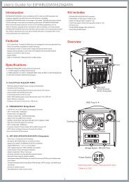
Overview<br />
Side Panel w/Venting<br />
Slim CD-ROM Carrier<br />
(Optional)<br />
Main Cable through hole<br />
w/ rubber pad<br />
Front Bezel<br />
(w/Key Lock)<br />
Intrusion<br />
switch<br />
USB & front<br />
Control cables<br />
Motherboard cage<br />
Front<br />
Card Reader (Optional)<br />
Slim ODD Cover<br />
USB 2.0 ports x2<br />
4x 3.5” HDD Carrier<br />
Front Control Display:<br />
• Power Status LED (Blue)<br />
• HDD Access LED (Amber)<br />
• LAN#1 Activities LED (Green)<br />
• LAN#2 Activities LED (Green)<br />
• Global Failure LED (Red)<br />
Front Control Switches:<br />
• Power On Switch<br />
• System Reset<br />
• Alarm Mute<br />
Back<br />
Low profile<br />
Slot opening<br />
LED VCC & recovery<br />
switch (optional)<br />
Pad Lock<br />
Rear 70mm fans (x2)<br />
Side Panel Screw<br />
Kensington lock<br />
Power connector<br />
www.chenbro.com 6
ES34169 Chassis User’s Manual<br />
Rev. A1<br />
To open the chassis for assembly of internal parts, users need to:<br />
• Remove the side panel and front bezel<br />
Side Panel Removal<br />
1 2<br />
■ Release the side panel thumb screw on the rear<br />
■ Push and slide the side panel toward rear to open the<br />
chassis<br />
Front Bezel Removal<br />
1 2<br />
■ Lift up the latch along the side to detach the bezel<br />
■ Detach the bezel from Slim ODD side gently<br />
3 4<br />
■ Angle the latch until it is 15 degree away from the<br />
chassis<br />
■ gently pull the bezel to make it detach<br />
www.chenbro.com 7
ES34169 Chassis User’s Manual<br />
Rev. A1<br />
Motherboard Cage Removal<br />
1 2<br />
■ Release 6 secure screws on the M/B cage<br />
■ Remove the motherboard cage<br />
3 4<br />
■ Disconnect the extension fan cables<br />
■ Detach the motherboard cage with System Cables<br />
(SATA, Power, Fan cables) through the cable routing hole<br />
5<br />
■ Finish detaching the M/B cage and make sure all the<br />
connection on backplane and PDB are still tight before<br />
assembly back the M/B cage<br />
www.chenbro.com 8
ES34169 Chassis User’s Manual<br />
Rev. A1<br />
Devices Installation<br />
Optional Parts:<br />
• Slim Optical Drive<br />
• 3.5” HDD<br />
• 4-in-1 Card Reader<br />
• Riser Card<br />
• 2.5” HDD<br />
Installing Slim Optical Drive (Slim ODD)<br />
Before install the slim ODD, the front bezel must be removed. The slim ODD carrier<br />
should be apart from the chassis.<br />
1 2<br />
■ Assemble the adapter board with attached screws<br />
onto Slim ODD<br />
■ Make sure the Slim ODD is fully seated with holder<br />
clip on the side.<br />
3 4<br />
■ Slide the assembled ODD into chassis<br />
■ Make sure the holder latch is secured when fully<br />
seated<br />
www.chenbro.com 9
ES34169 Chassis User’s Manual<br />
Rev. A1<br />
Installing 3.5” SATA-II Hard Drive<br />
1 2<br />
■ Remove the HDD Carrier from the chassis and place<br />
the SATA-II HDD into it.<br />
■ Attach the HDD screws on both sides<br />
3 4<br />
■ Slide in the assembled HDD into the chassis, suggest<br />
install by the ID definition on the front panel<br />
(No need to remove the front bezel)<br />
■ Make sure the carrier is fully seated<br />
Installing Card Reader<br />
1 2<br />
■ Detach the front screw of Card Reader holder<br />
■ Pull out the Card Reader holder<br />
www.chenbro.com 10
ES34169 Chassis User’s Manual<br />
Rev. A1<br />
3 4<br />
■ Remove the seal on the holder and make sure the<br />
sockets is right to the opening<br />
■ Attach screws to fix the Card Reader<br />
5 6<br />
■ Connect the short end of USB split cable to Card<br />
Reader<br />
■ Install the assembled Card Reader back to the<br />
chassis with screw<br />
7<br />
■ connect cable to USB port on M/B<br />
www.chenbro.com 11
ES34169 Chassis User’s Manual<br />
Rev. A1<br />
Installing Riser Card<br />
1 2<br />
■ Remove the cap on slot holder<br />
■ Detach the low profile slot bracket from rear window<br />
3 4<br />
■ Assemble riser and low profile add-on card<br />
■ Connect the cables before install.<br />
5 6<br />
■ Install the riser card onto motherboard.<br />
(Please pay attention to the cable arrangement)<br />
■ Attach screws on the rear side to secure the PCI card<br />
www.chenbro.com 12
ES34169 Chassis User’s Manual<br />
Rev. A1<br />
Installing 2.5” HDD<br />
1 2<br />
■ Place 2.5” HDD underneath the Slim ODD<br />
■ Fix the 2.5” HDD with attached screws<br />
Note: To install 2.5” HDD, disassemble the M/B cage is required.<br />
Connecting Devices<br />
• Four SATA-II cables for Hot-swap hard drive (HDD)<br />
• Power cables for M/B<br />
• Front panel I/O cables<br />
• USB 2.0 cable<br />
Connecting SATA-II Cables<br />
1 2<br />
■ Check the bundled cable with number tag<br />
■ Connect the SATA cables to the M/B properly<br />
Note: If there is no enough SATA port on M/B, users can either remove or keep the<br />
bundled P3/P4 SATA cable.<br />
www.chenbro.com 13
ES34169 Chassis User’s Manual<br />
Rev. A1<br />
Connecting Power Cables<br />
1 2<br />
■ The DC harness comes with 20+4 pin as main<br />
connection for different M/B requirement.<br />
■ Install and secure the DC harness cable to the M/B<br />
properly<br />
Connecting Front Panel I/O, LED and Slim ODD Cables<br />
a. USB 2.0 cable connection<br />
1<br />
■ Front USB cable should be connected to on-board USB<br />
header properly depends on different M/B.<br />
www.chenbro.com 14
ES34169 Chassis User’s Manual<br />
Rev. A1<br />
b. Front display cable connection<br />
1 2<br />
■ The cable with different connection for:<br />
Power on, HDD, LAN, FAIL and the front switch<br />
■ Connect to the M/B according to the M/B pin header<br />
definition properly.<br />
c. Slim ODD cable connection<br />
1 2<br />
■ Use power split cable in accessory pack for conversion<br />
of DC harness, small 4P is connected to the Slim<br />
ODD adaptor board<br />
■ Use either standard IDE / SATA cable from 3 rd party<br />
M/B, or use optional cable from <strong>Chenbro</strong> to connect<br />
to the Slim ODD adaptor board<br />
d. Cable management<br />
1 2<br />
■ Due to limited space inside the chassis, make sure all<br />
cable are connected properly and use the cable tie<br />
through the bridge land on side wall<br />
■ Tie up the cable so the cables are fixed in certain<br />
space.<br />
www.chenbro.com 15
ES34169 Chassis User’s Manual<br />
Rev. A1<br />
Power Supply<br />
Specification:<br />
Input Characteristics<br />
Output Characteristics<br />
Item Spec Item Spec<br />
Rated Input Voltage 115 V ~ 230 Vrms Output Voltage 3.3 V, 5 V, 12 V<br />
Input Voltage Range 90 ~ 264 Vrms Efficiency 80 %<br />
Input Frequency Range<br />
47 Hz ~ 63 Hz<br />
Protection:<br />
• Over-Voltage Protection<br />
• Short Circuit Protection<br />
• No Load Operation<br />
• Reset After Shutdown<br />
• Input Over Current Protection<br />
Environmental Requirements:<br />
• Temperature: -10 ~ 50 ℃ @ Operating; -40 ~ 70 @ Non-operating<br />
• Humidity: 5% ~ 90% @ Operating; 5% ~ 90% @ Non-operating<br />
Mechanical Dimension:<br />
50 mm * 35 mm * 183.7 mm<br />
www.chenbro.com 16
ES34169 Chassis User’s Manual<br />
Rev. A1<br />
2-port SATA-II Backplane<br />
ES34169 is integrated with two SATA-II backplanes to support four 3.5” HDD with<br />
hot-swap feature.<br />
Hardware Specification:<br />
Part Number<br />
Host Interface<br />
HDD Interface<br />
Hot-Swap<br />
Connectors<br />
Dimension<br />
80H104534-001 Rev. A1<br />
SATA 7-pin compatible<br />
SAS (22+7), SATA-II compatible<br />
Yes, allows user to on line replace Hard Disk Drive<br />
1. SATA-II x2 (to Host)<br />
2. SAS (22+7) x2 (for HDD)<br />
3. Standard 4P Power connector x 1 for +5V, +12V from<br />
power supply<br />
232(L) x 27.4(W) x 1.6(T) mm<br />
Backplane Connectors<br />
CN11 (HDD 1)<br />
CN21 (HDD 2)<br />
CN4<br />
CN1<br />
CN22<br />
CN12<br />
CN3<br />
(1) [CN11/CN21] : “22+7”pin SAS Connectors to HDD<br />
(2) [CN22/CN12] : SATA Connectors to Host<br />
(3) [CN1] : 4-pin Power Connector<br />
(4) [CN3] : HDD Access LED Signal Pin Header<br />
HDD 1<br />
HDD 2<br />
(5) [CN4] : HDD Failure LED Signal Pin Header<br />
HDD 1<br />
HDD 2<br />
Connecting Pin 1 & 2 to the CATHODE of the HDD failure connector on RAID<br />
card. Refer to the RAID card’s user manual for the detail pin definition.<br />
www.chenbro.com 17