Datasheet of GPS smart antenna module, NL-50xE Sirf3 series
Datasheet of GPS smart antenna module, NL-50xE Sirf3 series
Datasheet of GPS smart antenna module, NL-50xE Sirf3 series

Create successful ePaper yourself
Turn your PDF publications into a flip-book with our unique Google optimized e-Paper software.
Navilock Europe<br />
Beeskowdamm 13/15<br />
D-13595 Berlin-Zehlendorf<br />
Phone +49 30 84716503<br />
Email info@navilock.com<br />
Web www.navilock.com<br />
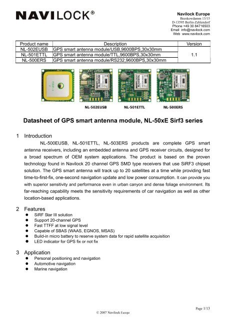
Product name Description Version<br />
<strong>NL</strong>-502EUSB <strong>GPS</strong> <strong>smart</strong> <strong>antenna</strong> <strong>module</strong>/USB,9600BPS,30x30mm<br />
<strong>NL</strong>-501ETTL <strong>GPS</strong> <strong>smart</strong> <strong>antenna</strong> <strong>module</strong>/TTL,9600BPS,30x30mm<br />
1.1<br />
<strong>NL</strong>-500ERS <strong>GPS</strong> <strong>smart</strong> <strong>antenna</strong> <strong>module</strong>/RS232,9600BPS,30x30mm<br />
<strong>Datasheet</strong> <strong>of</strong> <strong>GPS</strong> <strong>smart</strong> <strong>antenna</strong> <strong>module</strong>, <strong>NL</strong>-<strong>50xE</strong> <strong>Sirf3</strong> <strong>series</strong><br />
1 Introduction<br />
<strong>NL</strong>-500EUSB, <strong>NL</strong>-501ETTL, <strong>NL</strong>-503ERS products are complete <strong>GPS</strong> <strong>smart</strong><br />
<strong>antenna</strong> receivers, including an embedded <strong>antenna</strong> and <strong>GPS</strong> receiver circuits, designed for<br />
a broad spectrum <strong>of</strong> OEM system applications. The product is based on the proven<br />
technology found in Navilock 20 channel <strong>GPS</strong> SMD type receivers that use SiRF3 chipset<br />
solution. The <strong>GPS</strong> <strong>smart</strong> <strong>antenna</strong> will track up to 20 satellites at a time while providing fast<br />
time-to-first-fix, one-second navigation update and low power consumption. It can provide you<br />
with superior sensitivity and performance even in urban canyon and dense foliage environment. Its<br />
far-reaching capability meets the sensitivity requirements <strong>of</strong> car navigation as well as other<br />
location-based applications.<br />
2 Features<br />
• SiRF Star III solution<br />
• Support 20-channel <strong>GPS</strong><br />
• Fast TTFF at low signal level<br />
• Capable <strong>of</strong> SBAS (WAAS, EGNOS, MSAS)<br />
• Build-in micro battery to reserve system data for rapid satellite acquisition<br />
• LED indicator for <strong>GPS</strong> fix or not fix<br />
3 Application<br />
• Personal positioning and navigation<br />
• Automotive navigation<br />
• Marine navigation<br />
© 2007 Navilock Europe<br />
Page 1/13
Navilock Europe<br />
Beeskowdamm 13/15<br />
D-13595 Berlin-Zehlendorf<br />
Phone +49 30 84716503<br />
Email info@navilock.com<br />
Web www.navilock.com<br />
<strong>GPS</strong> <strong>antenna</strong><br />
SC-1513<br />
<strong>GPS</strong> <strong>module</strong><br />
USB bridge<br />
PC<br />
Micro battery<br />
Fig 3-1 System block diagram <strong>of</strong> <strong>NL</strong>-502EUSB<br />
<strong>GPS</strong> <strong>antenna</strong><br />
SC-1513<br />
<strong>GPS</strong> <strong>module</strong><br />
TTL level<br />
Host<br />
Micro battery<br />
Fig 3-2 System block diagram <strong>of</strong> <strong>NL</strong>-501ETTL<br />
<strong>GPS</strong> <strong>antenna</strong><br />
SC-1513<br />
<strong>GPS</strong> <strong>module</strong><br />
RS232<br />
transceiver<br />
PC<br />
Micro battery<br />
Fig 3-3 System block diagram <strong>of</strong> <strong>NL</strong>-500ERS<br />
© 2007 Navilock Europe<br />
Page 2/13
Navilock Europe<br />
Beeskowdamm 13/15<br />
D-13595 Berlin-Zehlendorf<br />
Phone +49 30 84716503<br />
Email info@navilock.com<br />
Web www.navilock.com<br />
4 <strong>GPS</strong> receiver<br />
Chip SiRF Star III GSC3f 7879<br />
Frequency L1 1575.42MHz, C/A code<br />
Channels<br />
Support 20 channels<br />
Update rate<br />
Acquisition Time<br />
1Hz<br />
Hot start (Open Sky)<br />
Cold Start (Open Sky)<br />
Position Accuracy<br />
Autonomous<br />
SBAS<br />
Datum<br />
WGS-84 (default)<br />
Max. Altitude < 60,000 ft<br />
Max. Velocity < 1,000 knots<br />
NMEA 0183 ver 3.0<br />
Protocol Support<br />
SiRF Binary<br />
< 2s<br />
38s (typical)<br />
< 10m (2D RMS)<br />
< 5m (2D RMS)<br />
9600 bps, 8 data bits, no parity, 1 stop bits<br />
(default)<br />
1Hz: GGA, GLL, GSA, GSV, RMC, VTG<br />
38400 bps, 8 data bits, no parity, 1 stop bits<br />
Table 4.1 Navigation Parameters<br />
Track smooth mode Enabled<br />
Static navigation mode Enabled<br />
5 S<strong>of</strong>tware interface<br />
5.1 NMEA output message<br />
Table 5.1-1 NMEA output message<br />
NMEA record Description<br />
GGA<br />
GLL<br />
GSA<br />
GSV<br />
RMC<br />
VTG<br />
Global positioning system fixed data<br />
Geographic position - latitude/longitude<br />
GNSS DOP and active satellites<br />
GNSS satellites in view<br />
Recommended minimum specific GNSS data<br />
Course over ground and ground speed<br />
© 2007 Navilock Europe<br />
Page 3/13
• GGA--- Global Positioning System Fixed Data<br />
Table 5.1-2 contains the values for the following example:<br />
$GPGGA,053740.000,2503.6319,N,12136.0099,E,1,08,1.1,63.8,M,15.2,M,,0000*64<br />
Table5.1- 2 GGA Data Format<br />
Name Example Units Description<br />
Message ID $GPGGA GGA protocol header<br />
UTC Time 053740.000 hhmmss.sss<br />
Latitude 2503.6319 ddmm.mmmm<br />
N/S indicator N N=north or S=south<br />
Longitude 12136.0099 dddmm.mmmm<br />
E/W Indicator E E=east or W=west<br />
Position Fix Indicator 1 See Table 5.1-3<br />
Satellites Used 08 Range 0 to 12<br />
HDOP 1.1 Horizontal Dilution <strong>of</strong> Precision<br />
MSL Altitude 63.8 meters<br />
Units M meters<br />
Geoid Separation 15.2 meters<br />
Units M meters<br />
Age <strong>of</strong> Diff. Corr. second Null fields when D<strong>GPS</strong> is not used<br />
Diff. Ref. Station ID 0000<br />
Checksum *64<br />
<br />
Table 5.1-3 Position Fix Indicators<br />
Value<br />
Description<br />
0 Fix not available or invalid<br />
1 <strong>GPS</strong> SPS Mode, fix valid<br />
2 Differential <strong>GPS</strong>, SPS Mode, fix<br />
valid<br />
3-5 Not supported<br />
6 Dead Reckoning Mode, fix valid<br />
End <strong>of</strong> message termination<br />
• GLL--- Geographic Position – Latitude/Longitude<br />
Table 5.1-4 contains the values for the following example:<br />
$GPGLL,2503.6319,N,12136.0099,E,053740.000,A,A*52<br />
Table 5.1-4 GLL Data Format<br />
Name Example Units Description<br />
Message ID $GPGLL GLL protocol header<br />
Latitude 2503.6319 ddmm.mmmm<br />
N/S indicator N N=north or S=south<br />
Longitude 12136.0099 dddmm.mmmm<br />
E/W indicator E E=east or W=west<br />
UTC Time 053740.000 hhmmss.sss<br />
Status A A=data valid or V=data not valid<br />
Mode A A=autonomous, D=D<strong>GPS</strong>, E=DR<br />
Checksum *52<br />
<br />
End <strong>of</strong> message termination<br />
Navilock Europe<br />
Beeskowdamm 13/15<br />
D-13595 Berlin-Zehlendorf<br />
Phone +49 30 84716503<br />
Email info@navilock.com<br />
Web www.navilock.com<br />
© 2007 Navilock Europe<br />
Page 4/13
• GSA---GNSS DOP and Active Satellites<br />
Table 5.1-5 contains the values for the following example:<br />
$GPGSA,A,3,24,07,17,11,28,08,20,04,,,,,2.0,1.1,1.7*35<br />
Table 5.1-5 GSA Data Format<br />
Name Example Units Description<br />
Message ID $GPGSA GSA protocol header<br />
Mode 1 A See Table 5.1-6<br />
Mode 2 3 See Table 5.1-7<br />
ID <strong>of</strong> satellite used 24 Sv on Channel 1<br />
ID <strong>of</strong> satellite used 07 Sv on Channel 2<br />
….<br />
….<br />
ID <strong>of</strong> satellite used Sv on Channel 12<br />
PDOP 2.0 Position Dilution <strong>of</strong> Precision<br />
HDOP 1.1 Horizontal Dilution <strong>of</strong> Precision<br />
VDOP 1.7 Vertical Dilution <strong>of</strong> Precision<br />
Checksum *35<br />
<br />
End <strong>of</strong> message termination<br />
Table 5.1-6 Mode 1<br />
Value<br />
M<br />
A<br />
Table 5.1-7 Mode 2<br />
Value<br />
Description<br />
1 Fix not available<br />
2 2D<br />
3 3D<br />
Description<br />
Manual- forced to operate in 2D or 3D mode<br />
Automatic-allowed to automatically switch<br />
2D/3D<br />
Navilock Europe<br />
Beeskowdamm 13/15<br />
D-13595 Berlin-Zehlendorf<br />
Phone +49 30 84716503<br />
Email info@navilock.com<br />
Web www.navilock.com<br />
• GSV---GNSS Satellites in View<br />
Table 5.1-8 contains the values for the following example:<br />
$GPGSV,3,1,12,28,81,285,42,24,67,302,46,31,54,354,,20,51,077,46*73<br />
$GPGSV,3,2,12,17,41,328,45,07,32,315,45,04,31,250,40,11,25,046,41*75<br />
$GPGSV,3,3,12,08,22,214,38,27,08,190,16,19,05,092,33,23,04,127,*7B<br />
Table 5.1-8 GSV Data Format<br />
Name Example Units Description<br />
Message ID $GPGSV GSV protocol header<br />
Total number <strong>of</strong> 3 Range 1 to 3<br />
messages 1<br />
Message number 1 1 Range 1 to 3<br />
Satellites in view 12<br />
Satellite ID 28 Channel 1 (Range 01 to 32)<br />
Elevation 81 degrees Channel 1 (Range 00 to 90)<br />
Azimuth 285 degrees Channel 1 (Range 000 to 359)<br />
SNR (C/No) 42 dB-Hz Channel 1 (Range 00 to 99, null when not tracking)<br />
Satellite ID 20 Channel 4 (Range 01 to 32)<br />
Elevation 51 degrees Channel 4 (Range 00 to 90)<br />
Azimuth 077 degrees Channel 4 (Range 000 to 359)<br />
SNR (C/No) 46 dB-Hz Channel 4 (Range 00 to 99, null when not tracking)<br />
Checksum *73<br />
<br />
End <strong>of</strong> message termination<br />
1. Depending on the number <strong>of</strong> satellites tracked multiple messages <strong>of</strong> GSV data may be<br />
required.<br />
© 2007 Navilock Europe<br />
Page 5/13
Navilock Europe<br />
Beeskowdamm 13/15<br />
D-13595 Berlin-Zehlendorf<br />
Phone +49 30 84716503<br />
Email info@navilock.com<br />
Web www.navilock.com<br />
• RMC---Recommended Minimum Specific GNSS Data<br />
Table 5.1-9 contains the values for the following example:<br />
$GPRMC,053740.000,A,2503.6319,N,12136.0099,E,2.69,79.65,100106,,,A*53<br />
Table 5.1-9 RMC Data Format<br />
Name Example Units Description<br />
Message ID $GPRMC RMC protocol header<br />
UTC Time 053740.000 hhmmss.sss<br />
Status A A=data valid or V=data not valid<br />
Latitude 2503.6319 ddmm.mmmm<br />
N/S Indicator N N=north or S=south<br />
Longitude 12136.0099 dddmm.mmmm<br />
E/W Indicator E E=east or W=west<br />
Speed over ground 2.69 knots True<br />
Course over ground 79.65 degrees<br />
Date 100106 ddmmyy<br />
Magnetic variation<br />
degrees<br />
Variation sense<br />
E=east or W=west (Not shown)<br />
Mode A A=autonomous, D=D<strong>GPS</strong>, E=DR<br />
Checksum *53<br />
<br />
End <strong>of</strong> message termination<br />
• VTG---Course Over Ground and Ground Speed<br />
Table 5.1-10 contains the values for the following example:<br />
$GPVTG,79.65,T,,M,2.69,N,5.0,K,A*38<br />
Table 5.1-10 VTG Data Format<br />
Name Example Units Description<br />
Message ID $GPVTG VTG protocol header<br />
Course over ground 79.65 degrees Measured heading<br />
Reference T True<br />
Course over ground degrees Measured heading<br />
Reference M Magnetic<br />
Speed over ground 2.69 knots Measured speed<br />
Units N Knots<br />
Speed over ground 5.0 km/hr Measured speed<br />
Units K Kilometer per hour<br />
Mode A A=autonomous, D=D<strong>GPS</strong>, E=DR<br />
Checksum *38<br />
<br />
End <strong>of</strong> message termination<br />
5.2 Proprietary NMEA input message<br />
Table 5.2-1 Message Parameters<br />
Start Sequence Payload Checksum End Sequence<br />
$PSRF 1 Data 2 *CKSUM 3 4<br />
1. Message Identifier consisting <strong>of</strong> three numeric characters. Input messages begin at MID 100.<br />
2. Message specific data. Refer to a specific message section for … definition.<br />
3. CKSUM is a two-hex character checksum as defined in the NMEA specification, NMEA-0183Standard<br />
For Interfacing Marine Electronic Devices. Use <strong>of</strong> checksums is required on all input messages.<br />
4. Each message is terminated using Carriage Return (CR) Line Feed (LF) which is \r\n which is hex 0D0A.<br />
Because \r\n are not printable ASCII characters, they are omitted from the example strings, but must be<br />
sent to terminate the message and cause the receiver to process that input message.<br />
Note: All fields in all proprietary NMEA messages are required, none are optional. All NMEA messages are<br />
comma delimited.<br />
© 2007 Navilock Europe<br />
Page 6/13
Navilock Europe<br />
Beeskowdamm 13/15<br />
D-13595 Berlin-Zehlendorf<br />
Phone +49 30 84716503<br />
Email info@navilock.com<br />
Web www.navilock.com<br />
Table 5.2-2 Proprietary NMEA input messages<br />
Message MID 1 Description<br />
SetSerialPort 100 Set PORT A parameters and protocol<br />
NavigationInitialization 101 Parameters required for start using X/Y/Z 2<br />
SetD<strong>GPS</strong>Port 102 Set PORT B parameters for D<strong>GPS</strong> input<br />
Query/Rate Control 103 Query standard NMEA message and/or set output rate<br />
LLANavigationInitialization 104 Parameters required for start using Lat/Lon/Alt 3<br />
Development Data On/Off 105 Development Data messages On/Off<br />
Select Datum 106 Selection <strong>of</strong> datum to be used for coordinate transformations<br />
1. Message Identification (MID).<br />
2. Input coordinates must be WGS84.<br />
3. Input coordinates must be WGS84<br />
• 100---SetSerialPort<br />
This command message is used to set the protocol (SiRF binary or NMEA) and/or the communication<br />
parameters (Baud, data bits, stop bits, and parity). Generally, this command is used to switch the <strong>module</strong><br />
back to SiRF binary protocol mode where a more extensive command message set is available. When a valid<br />
message is received, the parameters are stored in battery-backed SRAM and the Evaluation Receiver<br />
restarts using the saved parameters.<br />
Table 5.2-3 contains the input values for the following example:<br />
Switch to SiRF binary protocol at 9600,8,N,1<br />
$PSRF100,0,9600,8,1,0*0C<br />
Table 5.2-3 Set Serial Port Data Format<br />
Name Example Units Description<br />
Message ID $PSRF100 PSRF100 protocol header<br />
Protocol 0 0=SiRF binary, 1=NMEA<br />
Baud 9600 4800,9600,19200,38400,57600<br />
DataBits 8 8,7 1<br />
StopBits 1 0,1<br />
Parity 0 0=None, 1=Odd, 2=Even<br />
Checksum *0C<br />
<br />
End <strong>of</strong> message termination<br />
1. SiRF protocol is only valid for 8 data bits, 1 stop bit, and no parity.<br />
• 101---NavigationInitialization<br />
This command is used to initialize the Evaluation Receiver by providing current position (in X, Y, Z<br />
coordinates), clock <strong>of</strong>fset, and time. This enables the Evaluation Receiver to search for the correct satellite<br />
signals at the correct signal parameters. Correct initialization parameters enable the Evaluation Receiver to<br />
acquire signals quickly.<br />
Table 5.2-4 contains the input values for the following example:<br />
Start using known position and time<br />
$PSRF101,-2686700,-4304200,3851624,96000,497260,921,12,3*1C<br />
Table 5.2-4 Navigation Initialization Data Format<br />
Name Example Units Description<br />
Message ID $PSRF101 PSRF101 protocol header<br />
ECEF X -2686700 meters X coordinate position<br />
ECEF Y -4304200 meters Y coordinate position<br />
ECEF Z 3851624 meters Z coordinate position<br />
ClkOffset 96000 Hz Clock Offset <strong>of</strong> the Evaluation Receiver 1<br />
TimeOfWeek 497260 seconds <strong>GPS</strong> Time Of Week<br />
WeekNo 921 <strong>GPS</strong> Week Number<br />
ChannelCount 12 Range 1 to 12<br />
ResetCfg 3 See Table 5.2-5<br />
© 2007 Navilock Europe<br />
Page 7/13
Checksum *1C<br />
<br />
End <strong>of</strong> message termination<br />
1. Use 0 for last saved value if available. If this is unavailable, a default value <strong>of</strong> 96000 is used.<br />
Navilock Europe<br />
Beeskowdamm 13/15<br />
D-13595 Berlin-Zehlendorf<br />
Phone +49 30 84716503<br />
Email info@navilock.com<br />
Web www.navilock.com<br />
Table 5.2-5 Reset Configuration<br />
Hex<br />
Description<br />
0x01 Hot Start – All data valid<br />
0x02 Warm Start – Ephemeris cleared<br />
0x03 Warm Start (with Init) – Ephemeris cleared, initialization data loaded<br />
0x04 Cold Start – Clears all data in memory<br />
0x08 Clear Memory – Clears all data in memory and resets the receiver back to factory defaults<br />
• 102---SetD<strong>GPS</strong>Port<br />
This command is used to control the serial port used to receive RTCM differential corrections. Differential<br />
receivers may output corrections using different communication parameters. If a D<strong>GPS</strong> receiver is used that<br />
has different communication parameters, use this command to allow the receiver to correctly decode the data.<br />
When a valid message is received, the parameters are stored in battery-backed SRAM and the receiver<br />
restarts using the saved parameters.<br />
Table 5.2-6 contains the input values for the following example:<br />
Set D<strong>GPS</strong> Port to be 9600,8,N,1.<br />
$PSRF102,9600,8,1,0*12<br />
Table 5.2-6 Set <strong>GPS</strong> Port Data Format<br />
Name Example Units Description<br />
Message ID $PSRF102 PSRF102 protocol header<br />
Baud 9600 4800,9600,19200,38400<br />
DataBits 8 8,7<br />
StopBits 1 0,1<br />
Parity 0 0=None, 1=Odd, 2=Even<br />
Checksum *12<br />
<br />
End <strong>of</strong> message termination<br />
Note: RTCM is not supported.<br />
• 103---Query/Rate Control<br />
This command is used to control the output <strong>of</strong> standard NMEA messages GGA, GLL, GSA, GSV, RMC, and<br />
VTG. Using this command message, standard NMEA messages may be polled once, or setup for periodic<br />
output. Checksums may also be enabled or disabled depending on the needs <strong>of</strong> the receiving program.<br />
NMEA message settings are saved in battery-backed memory for each entry when the message is accepted.<br />
Table 5.2-7 contains the input values for the following example:<br />
1. Query the GGA message with checksum enabled<br />
$PSRF103,00,01,00,01*25<br />
2. Enable VTG message for a 1 Hz constant output with checksum enabled<br />
$PSRF103,05,00,01,01*20<br />
3. Disable VTG message<br />
$PSRF103,05,00,00,01*21<br />
Table 5.2-7 Query/Rate Control Data Format (See example 1)<br />
Name Example Units Description<br />
Message ID $PSRF103 PSRF103 protocol header<br />
Msg 00 See Table 5.2-8<br />
Mode 01 0=SetRate, 1=Query<br />
Rate 00 seconds Output – <strong>of</strong>f=0, max=255<br />
CksumEnable 01 0=Disable Checksum, 1=Enable Checksum<br />
Checksum *25<br />
<br />
End <strong>of</strong> message termination<br />
© 2007 Navilock Europe<br />
Page 8/13
Table 5.2-8 Messages<br />
Value<br />
0 GGA<br />
1 GLL<br />
2 GSA<br />
3 GSV<br />
4 RMC<br />
5 VTG<br />
6<br />
Description<br />
MSS (If internal beacon is<br />
supported)<br />
7 Not defined<br />
8 ZDA (if 1PPS output is supported)<br />
9 Not defined<br />
Navilock Europe<br />
Beeskowdamm 13/15<br />
D-13595 Berlin-Zehlendorf<br />
Phone +49 30 84716503<br />
Email info@navilock.com<br />
Web www.navilock.com<br />
• 104---LLANavigationInitialization<br />
This command is used to initialize the Evaluation Receiver by providing current position (in latitude, longitude,<br />
and altitude coordinates), clock <strong>of</strong>fset, and time. This enables the receiver to search for the correct satellite<br />
signals at the correct signal parameters. Correct initialization parameters enable the receiver to acquire<br />
signals quickly.<br />
Table 5.2-9 contains the input values for the following example:<br />
Start using known position and time.<br />
$PSRF104,37.3875111,-121.97232,0,96000,237759,1946,12,1*07<br />
Table 5.2-9 LLA Navigation Initialization Data Format<br />
Name Example Units Description<br />
Message ID $PSRF104 PSRF104 protocol header<br />
Lat 37.3875111 degrees Latitude position (Range 90 to –90)<br />
Lon -121.97232 degrees Longitude position (Range 180 to –180)<br />
Alt 0 meters Altitude position<br />
ClkOffset 96000 Hz Clock Offset <strong>of</strong> the Evaluation Receiver 1<br />
TimeOfWeek 237759 seconds <strong>GPS</strong> Time Of Week<br />
WeekNo 1946 Extended <strong>GPS</strong> Week Number (1024 added)<br />
ChannelCount 12 Range 1 to 12<br />
ResetCfg 1 See Table 5.2-10<br />
Checksum *07<br />
<br />
End <strong>of</strong> message termination<br />
1. Use 0 for last saved value if available. If this is unavailable, a default value <strong>of</strong> 96000 is<br />
used.<br />
Table 5.2-10 Messages<br />
Hex<br />
Description<br />
0x01 Hot Start – All data valid<br />
0x02 Warm Start – Ephemeris cleared<br />
0x03<br />
Warm Start (with Init) – Ephemeris<br />
cleared, initialization data loaded<br />
0x04 Cold Start – Clears all data in memory<br />
Clear Memory – Clears all data in<br />
0x08 memory and resets receiver back to<br />
factory defaults<br />
© 2007 Navilock Europe<br />
Page 9/13
Navilock Europe<br />
Beeskowdamm 13/15<br />
D-13595 Berlin-Zehlendorf<br />
Phone +49 30 84716503<br />
Email info@navilock.com<br />
Web www.navilock.com<br />
• 105---Development Data On/Off<br />
Use this command to enable development data information if you are having trouble getting commands<br />
accepted. Invalid commands generate debug information that enables you to determine the source <strong>of</strong> the<br />
command rejection. Common reasons for input command rejection are invalid checksum or parameter out <strong>of</strong><br />
specified range.<br />
Table 5.2-11 contains the input values for the following example:<br />
1. Debug On<br />
$PSRF105,1*3E<br />
2. Debug Off<br />
$PSRF105,0*3F<br />
Table 5.2-11 Development Data On/Off Data Format<br />
Name Example Units Description<br />
Message ID $PSRF105 PSRF105 protocol header<br />
Debug 1 0=Off, 1=On<br />
Checksum *3E<br />
<br />
End <strong>of</strong> message termination<br />
• 106---Select Datum<br />
$PS<strong>GPS</strong> receivers perform initial position and velocity calculations using an earth-centered earth-fixed<br />
(ECEF) coordinate system. Results may be converted to an earth model (geoid) defined by the selected<br />
datum. The default datum is WGS 84 (World Geodetic System 1984) which provides a worldwide common<br />
grid system that may be translated into local coordinate systems or map datums. (Local map datums are a<br />
best fit to the local shape <strong>of</strong> the earth and not valid worldwide.)<br />
Table 5.2-12 contains the input values for the following example:<br />
Datum select TOKYO_MEAN<br />
$PSRF106,178*32<br />
Table 5.2-12 Development Data On/Off Data Format<br />
Name Example Units Description<br />
Message ID $PSRF106 PSRF106 protocol header<br />
Datum 178 21=WGS84<br />
178=TOKYO_MEAN<br />
179=TOKYO_JAPAN<br />
180=TOKYO_KOREA<br />
181=TOKYO_OKINAWA<br />
Checksum *32<br />
<br />
End <strong>of</strong> message termination<br />
© 2007 Navilock Europe<br />
Page 10/13
Navilock Europe<br />
Beeskowdamm 13/15<br />
D-13595 Berlin-Zehlendorf<br />
Phone +49 30 84716503<br />
Email info@navilock.com<br />
Web www.navilock.com<br />
6 LED indicator<br />
The red LED is an indicator <strong>of</strong> <strong>GPS</strong> positioning status. In continuous power mode, it flashes<br />
once per second when position is fixed. Otherwise it flashes fast. The timing in detail is as<br />
below.<br />
Fig 6.1 LED indicator <strong>of</strong> <strong>GPS</strong> positioning status<br />
7 Pin assignment and descriptions<br />
Fig 7.1 Pin assignment <strong>of</strong> <strong>NL</strong>-500ERS, <strong>NL</strong>-501ETTL and <strong>NL</strong>502EUSB<br />
• <strong>NL</strong>-502EUSB<br />
Pin # Name Type Description<br />
1 VBUS P USB power input<br />
2 D- D- line<br />
3 D+ D+ line<br />
4 GND P Ground<br />
5 Shield P Ground<br />
© 2007 Navilock Europe<br />
Page 11/13
Navilock Europe<br />
Beeskowdamm 13/15<br />
D-13595 Berlin-Zehlendorf<br />
Phone +49 30 84716503<br />
Email info@navilock.com<br />
Web www.navilock.com<br />
• <strong>NL</strong>-501ETTL<br />
Pin # Name Type Description<br />
1 VCC P Power input<br />
2 RX I Data input (TTL level)<br />
3 TX O Data output (TTL level)<br />
4 GND P Ground<br />
5 GND P Ground<br />
• <strong>NL</strong>-500ERS<br />
Pin # Name Type Description<br />
1 VCC P Power input<br />
2 RX I Data input (RS232 level)<br />
3 TX O Data output (RS232 level)<br />
4 GND P Ground<br />
5 GND P Ground<br />
8 DC & Temperature characteristics<br />
8.1 DC Electrical characteristics<br />
Parameter Symbol Product Min. Typ. Max. Units<br />
Input voltage<br />
Input current<br />
VCC<br />
Icc<br />
<strong>NL</strong>-502EUSB<br />
<strong>NL</strong>-501ETTL<br />
<strong>NL</strong>-500ERS<br />
<strong>NL</strong>-502EUSB<br />
<strong>NL</strong>-501ETTL<br />
<strong>NL</strong>-500ERS<br />
4.75<br />
3<br />
4<br />
5<br />
3.3<br />
5<br />
5.25<br />
4.2<br />
6<br />
V<br />
70 (1)<br />
62 (2)<br />
63 (1) mA<br />
High Level Input Voltage VI H <strong>NL</strong>-501ETTL 0.7*VOUT (3) 3.6 V<br />
Low Level Input Voltage VI L <strong>NL</strong>-501ETTL -0.3 0.3*VOUT (3) V<br />
High Level Input Current I I H <strong>NL</strong>-501ETTL -10 60 uA<br />
Low Level Input Current I I L <strong>NL</strong>-501ETTL -10 60 uA<br />
High Level Output Voltage VOH <strong>NL</strong>-501ETTL 0.75*VOUT (3) V<br />
Low Level Output Voltage VOL <strong>NL</strong>-501ETTL 0.25*VOUT (3) V<br />
High Level Output Current IOH <strong>NL</strong>-501ETTL 2 mA<br />
Low Level Output Current IOL <strong>NL</strong>-501ETTL 2 mA<br />
1. Measured when position fix is available and input voltage is 5V.<br />
2. Measured when position fix is available and input voltage is 3.3V.<br />
3. 2.79V≦VOUT≦2.91V.<br />
8.2 Temperature characteristics<br />
Parameter Symbol Product Min. Typ. Max. Units<br />
<strong>NL</strong>-500ERS, <strong>NL</strong>-<br />
Operating Temperature Topr<br />
-30 - 85<br />
501ETTL, <strong>NL</strong>-502EUSB<br />
℃<br />
Storage Temperature Tstg<br />
-40 25 85 ℃<br />
<strong>NL</strong>-500ERS, <strong>NL</strong>-<br />
501ETTL, <strong>NL</strong>-502EUSB<br />
© 2007 Navilock Europe<br />
Page 12/13
Navilock Europe<br />
Beeskowdamm 13/15<br />
D-13595 Berlin-Zehlendorf<br />
Phone +49 30 84716503<br />
Email info@navilock.com<br />
Web www.navilock.com<br />
9 Mechanical specification<br />
• <strong>NL</strong>-500ERS, <strong>NL</strong>-501ETTL and <strong>NL</strong>-502EUSB<br />
© 2007 Navilock Europe<br />
Page 13/13