Sentaurus Structure Editor Device Editor and ... - Synopsys.com
Sentaurus Structure Editor Device Editor and ... - Synopsys.com
Sentaurus Structure Editor Device Editor and ... - Synopsys.com

Create successful ePaper yourself
Turn your PDF publications into a flip-book with our unique Google optimized e-Paper software.
Data Sheet<br />
<strong>Sentaurus</strong> <strong>Structure</strong> <strong>Editor</strong><br />
<strong>Device</strong> <strong>Editor</strong> <strong>and</strong> Process<br />
Emulator<br />
Overview<br />
<strong>Sentaurus</strong> <strong>Structure</strong> <strong>Editor</strong> is a device editor <strong>and</strong> process emulator based on CAD technology. It has three distinct operational<br />
modes: 2D structure editing, 3D structure editing, <strong>and</strong> 3D process emulation. Geometric <strong>and</strong> process emulation operations<br />
can be mixed freely, adding more flexibility to the generation of 3D structures. In addition, <strong>Sentaurus</strong> <strong>Structure</strong> <strong>Editor</strong> offers<br />
state-of-the-art visualization. <strong>Structure</strong>s are displayed as they are created <strong>and</strong> powerful view filters make it possible to select a<br />
subset of regions <strong>and</strong> to make regions transparent.<br />
<strong>Sentaurus</strong> <strong>Structure</strong> <strong>Editor</strong> is powered by the ACIS® geometry kernel, which is well proven <strong>and</strong> widely used as the basis of<br />
many different applications.<br />
The graphical user interface (GUI) of <strong>Sentaurus</strong> <strong>Structure</strong> <strong>Editor</strong><br />
features a <strong>com</strong>m<strong>and</strong>-line window, in which script <strong>com</strong>m<strong>and</strong>s<br />
corresponding to the GUI operations are printed. Script<br />
<strong>com</strong>m<strong>and</strong>s can also be entered directly at the <strong>com</strong>m<strong>and</strong>-line<br />
window. Doping profiles <strong>and</strong> meshing strategies can be defined<br />
interactively. Placements are visualized as semitransparent boxes<br />
for easy verification.<br />
All doping <strong>and</strong> meshing options of the <strong>Synopsys</strong> meshing tools<br />
Mesh <strong>and</strong> Noffset3D are supported. The meshing tools can be<br />
called from the GUI <strong>and</strong> the generated mesh <strong>and</strong> doping profiles<br />
can be automatically visualized in <strong>Sentaurus</strong> <strong>Structure</strong> <strong>Editor</strong> or<br />
Tecplot SV.<br />
Benefits<br />
• Use direct CAD operations <strong>and</strong> process emulation steps to<br />
create 2D <strong>and</strong> 3D structures<br />
• Interactive graphical user interface with state-of-the-art<br />
visualization<br />
• User-friendly graphical user interface <strong>and</strong> front end for <strong>Synopsys</strong><br />
meshing engines<br />
• Firmly based on the ACIS® solid geometry modeling kernel<br />
• Scriptable with recording <strong>and</strong> replaying <strong>com</strong>m<strong>and</strong>s from the GUI<br />
• Versatile <strong>and</strong> integrated <strong>com</strong>m<strong>and</strong>-line window for script<br />
execution<br />
All interactive operations are recorded <strong>and</strong> a journal file can<br />
be saved, enabling users to reconstruct device geometries by<br />
rerunning the journaled script file.
Z<br />
Y<br />
X<br />
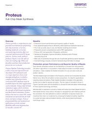
Figure 1. Main graphical user interface of <strong>Sentaurus</strong> <strong>Structure</strong> <strong>Editor</strong>.<br />
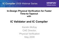
Figure 2. Visualization of three-dimensional grid with associated doping<br />
distribution.<br />
Two-Dimensional <strong>and</strong> Three-Dimensional <strong>Device</strong> <strong>Editor</strong><br />
Two-dimensional <strong>and</strong> three-dimensional device models are created<br />
geometrically using 2D or 3D primitives such as rectangles,<br />
polygons, cuboids, cylinders, <strong>and</strong> spheres. Three-dimensional<br />
regions can also be created by extruding 2D objects or sweeping<br />
2D objects along a path. Rounded edges are generated by<br />
filleting, 3D edge blending, <strong>and</strong> chamfering. The way in which<br />
the overlap between new <strong>and</strong> existing objects is resolved can<br />
be explicitly selected, which allows greater flexibility in structure<br />
generation. Complex shapes are generated by performing Boolean<br />
operations (union, subtract, intersect) between elements.<br />
Parametric <strong>Device</strong> <strong>Structure</strong>s<br />
The script files of <strong>Sentaurus</strong> <strong>Structure</strong> <strong>Editor</strong> use a LISP-like<br />
programming language called Scheme. Scripting makes it easy<br />
to create parametric structures using simple variables or variables<br />
defined as functions of other variables, conditional constructs such<br />
as ‘if’ or ‘do while’ blocks, <strong>and</strong> loops.<br />
Model Tessellation<br />
<strong>Sentaurus</strong> <strong>Structure</strong> <strong>Editor</strong> models can contain analytic (circular,<br />
elliptical) curves <strong>and</strong> spline curves in 2D, <strong>and</strong> analytic (spherical,<br />
cylindrical, elliptical, toroidal) curves <strong>and</strong> spline curves or NURBS<br />
surfaces in 3D. These curved edges <strong>and</strong> faces must be tessellated<br />
to generate DF–ISE boundary output. Global <strong>and</strong> facewise<br />
refinements can be used to specify the required surface resolution<br />
(surface <strong>and</strong> normal vector tolerance), <strong>and</strong> the aspect ratio <strong>and</strong><br />
maximal edge length of the elements in the surface tessellation.<br />
Mesh <strong>and</strong> Doping Visualization<br />
From <strong>Sentaurus</strong> <strong>Structure</strong> <strong>Editor</strong>, the <strong>Synopsys</strong> meshers can<br />
be accessed conveniently. Mesh <strong>and</strong> Noffset3D can be fully<br />
configured from <strong>Sentaurus</strong> <strong>Structure</strong> <strong>Editor</strong>. The meshing<br />
strategies (local refinements), constant <strong>and</strong> analytic dopings, <strong>and</strong><br />
submesh inclusion can be defined. The generated grid <strong>and</strong> data<br />
files can be visualized in <strong>Sentaurus</strong> <strong>Structure</strong> <strong>Editor</strong>.<br />
2
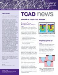
Figure 3. Selected steps from a process emulation sequence that Procem typically performs. The final structure is a FinFET.<br />
Three-Dimensional Process Emulator<br />
In process emulation mode (Procem), <strong>Sentaurus</strong> <strong>Structure</strong> <strong>Editor</strong><br />
translates processing steps, such as etching <strong>and</strong> deposition,<br />
patterning, fill <strong>and</strong> polish, into geometric operations. Procem<br />
supports various options such as isotropic <strong>and</strong> anisotropic etching<br />
<strong>and</strong> deposition, rounding, <strong>and</strong> blending to account for specific<br />
processing effects.<br />
Procem is fully integrated into Ligament, which is part of <strong>Sentaurus</strong><br />
Workbench. Process emulation flows can be created easily <strong>and</strong><br />
conveniently using the Ligament Flow <strong>Editor</strong>. External layout files<br />
in CIF or GDSII format can be imported into the Ligament Layout<br />
<strong>Editor</strong>.<br />
Implantation<br />
Doping profile distributions, including shadowing effects <strong>and</strong><br />
nonplanar surfaces, can be defined using imp3d – an implantation<br />
engine – thereby emulating in 3D the final distribution of an implant<br />
operation that can include diffusion.<br />
<strong>Sentaurus</strong> <strong>Structure</strong> <strong>Editor</strong> can use imp3d to create a doping<br />
profile in the device, emulating the final profile of doping<br />
implantation <strong>and</strong> diffusion steps. The result is a distribution<br />
described by a Pearson function whose moment parameters are<br />
defined by the user: st<strong>and</strong>ard deviation, skewness, <strong>and</strong> kurtosis.<br />
An additional exponential tail parameter is available.<br />
Mix-<strong>and</strong>-Match<br />
The (2D <strong>and</strong> 3D) device editor modes <strong>and</strong> three-dimensional<br />
process emulation mode can be mixed freely in a script or<br />
interactively by entering Procem Scheme <strong>com</strong>m<strong>and</strong>s at the<br />
<strong>com</strong>m<strong>and</strong>-line window. For example, a geometrically generated<br />
trench can be coated with a thin oxide layer by using a single<br />
deposition step.<br />
3
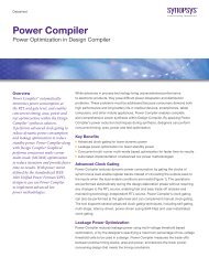
Figure 4. Local <strong>and</strong> global tessellation control for polyhedral output.<br />
Features<br />
• Proven CAD technology using ACIS® <strong>com</strong>putational geometry<br />
kernel <strong>and</strong> interface with CAD file formats (SAT)<br />
• Intuitive graphical user interface<br />
• Immediate visualization of current geometry<br />
• Interactive scripting, including capability to record GUI actions,<br />
<strong>and</strong> type-<strong>and</strong>-paste script <strong>com</strong>m<strong>and</strong>s<br />
• Generation of 2D <strong>and</strong> 3D primitives: rectangles, circles,<br />
polygons, cuboids, cylinders, <strong>and</strong> spheres<br />
• Rounding of corners <strong>and</strong> edges by filleting <strong>and</strong> chamfering<br />
• Extruding <strong>and</strong> sweeping 2D objects<br />
• Control of overlap resolution<br />
• Assignment of contacts to edges <strong>and</strong> faces<br />
• Two-dimensional boundary simplification<br />
• Interactive definitions of doping <strong>and</strong> meshing strategies<br />
• Visual control of doping <strong>and</strong> meshing placements<br />
• Direct calls to the <strong>Synopsys</strong> meshing engines<br />
• Patterning with layout <strong>and</strong> masks (CIF <strong>and</strong> GDSII formats)<br />
• Deposition <strong>and</strong> etching: isotropic <strong>and</strong> anisotropic, <strong>and</strong> various<br />
blending options<br />
• Fill <strong>and</strong> polish, <strong>and</strong> strip<br />
• Implant (analytic profiles)<br />
• Fully integrated into the process simulation environment<br />
Ligament<br />
Supported Platforms<br />
• AMD64 (Opteron) 64-bit<br />
• HP (PA-RISC 2.0) HP-UX 64-bit<br />
• Sun (SPARC) Solaris 64-bit<br />
• x86 (IA-32) Linux 32-bit<br />
700 East Middlefield Road, Mountain View, CA 94043 T 650 962 5000 www.synopsys.<strong>com</strong><br />
<strong>Synopsys</strong> <strong>and</strong> the <strong>Synopsys</strong> logo are registered trademarks of <strong>Synopsys</strong>, Inc. All other products or service<br />
names mentioned herein are trademarks of their respective holders <strong>and</strong> should be treated as such.<br />
© 2005 <strong>Synopsys</strong>, Inc. All rights reserved. 10/05.RB.WO.05-13604