PDF Download - Glidewell Dental Labs
PDF Download - Glidewell Dental Labs
PDF Download - Glidewell Dental Labs

You also want an ePaper? Increase the reach of your titles
YUMPU automatically turns print PDFs into web optimized ePapers that Google loves.
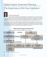
Cook-Waite Lidocaine ® HCI 2% and Epinephrine 1:100,000<br />
(Kodak <strong>Dental</strong> Systems; Rochester, N.Y.). The upper surgical<br />
guide was inserted and stabilized by both the doctor<br />
and assistant (Fig. 6). Once a confirmed fit was verified, the<br />
1.5 mm diameter pilot drill was introduced into the guide<br />
sleeve (Fig. 7). The guide sleeve orients the pilot drill in the<br />
correct trajectory. The top of the sleeves are set at 9 mm<br />
from the top of the implant, and this vertical distance must<br />
be accounted for when determining proper drill depth. The<br />
recommended procedure for unguided site preparation is<br />
to drill to a depth that is approximately one-half the length<br />
of the implant, plus the tissue depth. In this case, the six<br />
mini implants to be placed in the maxilla were each 10 mm<br />
in length, so half of that length (5 mm) plus the tissue depth<br />
(approximately 2 mm) accounted for 7 mm of drill depth.<br />
Adding the 9 mm length for the guide sleeves necessitated<br />
an overall drill depth of 16 mm. Each Cortical Bone Drill<br />
included with the Inclusive Mini Implant System has depth<br />
markings at 10 mm, 13 mm and 15 mm, so drilling to 16 mm<br />
meant drilling just past the last mark on the drill.<br />
The drilling process was conducted at 1250 RPM under<br />
copious irrigation using the MD 20 Dual Motor System<br />
(Nouvag USA; Lake Hughes, Calif.). For the best chance of<br />
long-term implant success, it is important to minimize tissue<br />
damage and thermal trauma to the bone. 6 Because Inclusive<br />
Mini Implants are self-tapping, only a single pilot drill is<br />
required; no additional finishing bits or bone formers are<br />
needed. The implant will follow the path created by the<br />
pilot drill and compress and condense the bone to help<br />
achieve immediate primary stability. In certain cases, it is<br />
possible to engage both cortical plates for even greater stability.<br />
All six pilot holes were made following the same process,<br />
and the surgical guide was removed. A periodontal<br />
probe was used to confirm that all pilot holes in the cortical<br />
bone did not perforate in the buccal-lingual dimension.<br />
Figure 10: Pilot drill engaged in the mandibular surgical guide<br />
The implant will follow<br />
the path created by<br />
the pilot drill and<br />
compress and condense<br />
the bone to help<br />
achieve immediate<br />
primary stability.<br />
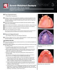
One at a time, the Inclusive Mini Implants were removed<br />
from their sterile packs and glass vials and hand-tightened<br />
with the attached carrier until they were difficult to turn<br />
(Fig. 8). The Handpiece Mini Implant Driver attachment<br />
was then used to gently rotate each mini implant to depth<br />
(Fig. 9). Final seating was verified at 35 Ncm using the<br />
Torque/Ratchet Wrench included in the Inclusive Surgical<br />
Instrumentation Kit.<br />
The same process was repeated for the mandible using the<br />
lower surgical guide (Fig. 10). In this case, the Inclusive Mini<br />
Implants were 13 mm in length, so the pilot drill was taken<br />
to a depth of approximately 18 mm, or almost to the hub.<br />
The overall length of the pilot drill from cutting tip to shank<br />
is approximately 20 mm. Once again, final seating was verified<br />
at 35 Ncm to ensure primary stability (Fig. 11).<br />
Figure 11: Final placement of four Inclusive Mini Implants in the mandible<br />
– Three-Dimensional Treatment Planning with Surgical Guides and Mini Implant-Retained Dentures – 29